EP4506288A1 - Support device for a reel, packaging machine having a support device for a reel, method for coupling a reel to a support device and method for uncoupling a reel from a support device - Google Patents
Support device for a reel, packaging machine having a support device for a reel, method for coupling a reel to a support device and method for uncoupling a reel from a support device Download PDFInfo
- Publication number
- EP4506288A1 EP4506288A1 EP24184212.9A EP24184212A EP4506288A1 EP 4506288 A1 EP4506288 A1 EP 4506288A1 EP 24184212 A EP24184212 A EP 24184212A EP 4506288 A1 EP4506288 A1 EP 4506288A1
- Authority
- EP
- European Patent Office
- Prior art keywords
- reel
- support device
- clamping group
- tubular holder
- locking
- Prior art date
- Legal status (The legal status is an assumption and is not a legal conclusion. Google has not performed a legal analysis and makes no representation as to the accuracy of the status listed.)
- Pending
Links
Images



Classifications
-
- B—PERFORMING OPERATIONS; TRANSPORTING
- B65—CONVEYING; PACKING; STORING; HANDLING THIN OR FILAMENTARY MATERIAL
- B65H—HANDLING THIN OR FILAMENTARY MATERIAL, e.g. SHEETS, WEBS, CABLES
- B65H19/00—Changing the web roll
- B65H19/10—Changing the web roll in unwinding mechanisms or in connection with unwinding operations
- B65H19/12—Lifting, transporting, or inserting the web roll; Removing empty core
-
- B—PERFORMING OPERATIONS; TRANSPORTING
- B65—CONVEYING; PACKING; STORING; HANDLING THIN OR FILAMENTARY MATERIAL
- B65H—HANDLING THIN OR FILAMENTARY MATERIAL, e.g. SHEETS, WEBS, CABLES
- B65H2301/00—Handling processes for sheets or webs
- B65H2301/40—Type of handling process
- B65H2301/41—Winding, unwinding
- B65H2301/413—Supporting web roll
- B65H2301/4132—Cantilever arrangement
- B65H2301/41324—Cantilever arrangement linear movement of roll support
- B65H2301/4133—Cantilever arrangement linear movement of roll support special features
- B65H2301/41335—Cantilever arrangement linear movement of roll support special features locking mechanism for roll, e.g. axial flange
-
- B—PERFORMING OPERATIONS; TRANSPORTING
- B65—CONVEYING; PACKING; STORING; HANDLING THIN OR FILAMENTARY MATERIAL
- B65H—HANDLING THIN OR FILAMENTARY MATERIAL, e.g. SHEETS, WEBS, CABLES
- B65H2801/00—Application field
- B65H2801/69—Form fill-and-seal machines
Definitions
- the present invention relates to support device for carrying a reel comprising a tubular holder and a web of packaging material wound about the tubular holder.
- the support device is configured to allow placing the reel within a packaging machine and rotating the reel around a rotation axis.
- the present invention also relates to a packaging machine, in particular a packaging machine for producing sealed packages of a pourable product, even more particular of a pourable food product, having a magazine unit comprising a support device for a reel.
- the present invention also relates to a method for coupling a reel comprising a tubular holder and a web of packaging material wound about the tubular holder to a support device.
- the present invention also relates to a method for uncoupling a tubular holder of an exhausted reel from a support device.
- liquid or pourable food products such as fruit juice, UHT (ultra-high-temperature treated) milk, wine, tomato sauce, etc.
- UHT ultra-high-temperature treated milk
- wine tomato sauce
- etc. are sold in packages made of sterilized packaging material.
- a typical example is the parallelepiped-shaped package for liquid or pourable food products known as Tetra Brik Aseptic (registered trademark), which is made by sealing and folding laminated strip packaging material.
- the packaging material has a multilayer structure comprising a base layer, e.g. of paper, covered on both sides with layers of heat-seal plastic material, e.g. polyethylene.
- the packaging material also comprises a layer of oxygen-barrier material (an oxygen-barrier layer), e.g. an aluminum foil, which is superimposed on a layer of heat-seal plastic material, and is in turn covered with another layer of heat-seal plastic material forming the inner face of the package eventually contacting the food product.
- Packages of this sort are normally produced on fully automatic packaging machines, which advance a web of packaging material through a sterilization apparatus for sterilizing the web of packaging material at a sterilization station and to an isolation chamber (a closed and sterile environment) in which the sterilized web of packaging material is maintained and advanced.
- an isolation chamber a closed and sterile environment
- the web of packaging material is folded and sealed longitudinally at a tube forming station to form a tube having a longitudinal seam portion, the tube being further fed along a vertical advancing direction.
- the tube is filled with a pourable product, in particular a pourable food product, and is transversally sealed and subsequently cut along equally spaced transversal cross sections within a package forming apparatus of the packaging machine during advancement along the vertical advancing direction.
- a pourable product in particular a pourable food product
- Pillow packages are so obtained, each pillow package having a longitudinal sealing band, a top transversal sealing band and a bottom transversal sealing band.
- a typical packaging machine comprises a magazine unit for hosting the web of packaging material, a conveying device for advancing the web of packaging material along a web advancement path and the tube formed from the web of packaging material along a tube advancement path, the sterilizing apparatus for sterilizing the web of packaging material prior to its formation into the tube, a tube forming and sealing device at least partially arranged within the isolation chamber and being configured to form the tube from the advancing web of packaging material and to longitudinally seal the tube, a filling device for filling the tube with the pourable product and the package forming apparatus adapted to form, transversally seal and cut individual packages from the tube of packaging material.
- a typical magazine unit comprises at least one support device configured to carry a reel comprising a tubular holder and the web of packaging material wound about the tubular holder.
- a typical support device comprises an elongated spindle and a first clamping group and a second clamping group connected to the elongated spindle.
- the first clamping group and the second clamping group clamp the reel between one another, in particular by laterally engaging the tubular holder and the web of packaging material wound about the tubular holder.
- an operator In order to couple the reel to the support device an operator has to remove the second clamping group from the elongated spindle and to guide the spindle through the (hollow) tubular holder until the first clamping group laterally abuts against the reel. Afterwards, the operator mounts the second clamping group again to the elongated spindle and pushes the second clamping group into lateral abutment with the reel. Then, the operator has to fasten the second clamping group to the elongated spindle.
- Number 1 indicates as a whole a packaging machine for producing sealed packages 2 of a pourable product, in particular a pourable food product, such as milk, milk drinks, yoghurt, yoghurt drinks, fruit juice, wine, tomato sauce, emulsions, beverages containing pulp, salt, sugar, etc.
- a pourable food product such as milk, milk drinks, yoghurt, yoghurt drinks, fruit juice, wine, tomato sauce, emulsions, beverages containing pulp, salt, sugar, etc.
- packaging machine 1 may be configured to produce packages 2 from a web of packaging material 3, preferentially a web of multilayer packaging material.
- web of packaging material 3 may have heat seal properties (i.e. portions of the multilayer packaging material can be sealed to one another).
- web of packaging material 3 may comprise at least one layer of fibrous material, such as e.g. paper or cardboard, and at least two layers of heat-seal plastic material, e.g. polyethylene, interposing the layer of fibrous material in between one another. Preferentially, one of these two layers of heat-seal plastic material may define the inner face of packages 2 contacting the pourable product.
- fibrous material such as e.g. paper or cardboard
- heat-seal plastic material e.g. polyethylene
- web of packaging material 3 may also comprise a layer of gas- and light-barrier material, e.g. aluminum foil or ethylene vinyl alcohol (EVOH) film, preferentially being arranged between one of the layers of the heat-seal plastic material and the layer of fibrous material.
- gas- and light-barrier material e.g. aluminum foil or ethylene vinyl alcohol (EVOH) film
- web of packaging material 3 may also comprise a further layer of heat-seal plastic material being interposed between the layer of gas- and light-barrier material and the layer of fibrous material.
- web of packaging material 3 may comprise successively arranged patterns, each pattern defining a final graphical pattern of the respective package 2.
- packaging machine 1 operates, in use, such to guarantee that packages 2 comprise the respective pattern.
- packaging machine 1 may be configured to produce packages 2 by forming a tube 4 from web of packaging material 3, longitudinally sealing tube 4, filling tube 4 with the pourable product and to transversally seal, and preferentially transversally cut tube 4.
- each package 2 may extend along a longitudinal axis A.
- each package 2 may comprise at least a first transversal sealing band 5a arranged at a first end of package 2, and preferentially also a second transversal sealing band 5b arranged at a second end of package 2 opposite to the first end.
- each first transversal sealing band 5a may be substantially spaced apart from the respective second transversal sealing band 5b along the respective longitudinal axis A.
- each package 2 may also comprise a longitudinal seam portion 6.
- each first transversal sealing band 5a and/or each second transversal sealing band 5b may be transversal, preferentially perpendicular, to the respective longitudinal seam portion 6.
- packaging machine 1 may comprise:
- conveying device 13 may be configured to advance web of packaging material 3 to a tube forming station 14, at which, in use, web of packaging material 3 is formed into tube 4, and configured to advance tube 4 along a tube advancement path Q.
- packaging machine 1 may also comprise:
- packaging machine 1 may also comprise an isolation chamber 18, preferentially delimiting an inner environment 19 from an outer environment 20.
- inner environment 19 may be a sterile environment, preferably containing a controlled atmosphere.
- tube forming and sealing device 15 may be at least partially arranged within and configured to fold and longitudinally seal tube 4 within isolation chamber 18, preferentially inner environment 19.
- packaging machine 1 may also comprise a sterilizing unit configured to sterilize the, in use, advancing web of packaging material 3, preferentially the sterilization unit being arranged upstream of tube forming and sealing device 15 along web advancement path P and/or downstream of host station 12.
- conveying device 13 may be configured to advance tube 4 and any intermediates of tube 4 along tube advancement path Q, preferentially from tube forming and sealing device 15 to and/or at least partially within package forming unit 17.
- any configuration of web of packaging material 3 is meant prior to obtaining the tube structure and after folding of web of packaging material 3 by tube forming and sealing device 15 has started.
- the intermediates of tube 4 are a result of the gradual folding of web of packaging material 3 so as to obtain tube 4, preferentially by overlapping the (longitudinal) edges of web of packaging material 3 with one another.
- tube forming and sealing device 15 may be arranged such that tube 4 may have a vertical orientation.
- filling device 16 may comprise a filling pipe 23 being configured to direct, in use, the pourable product into tube 4.
- filling pipe 23 may, in use, be at least partially placed within tube 4 for feeding, in use, the pourable product into tube 4.
- package forming unit 17 may comprise a plurality of, operative devices, each one configured to manipulate, preferentially to at least partially form, to at least transversally seal and to transversally cut, tube 4 for obtaining packages 2.
- magazine unit 10 may be arranged upstream of isolation chamber 18 and/or tube forming and sealing device 15 and/or packaging forming unit 17.
- magazine unit 10 comprises at least one support device 25 configured to carry at least one reel 11.
- each reel 11 may comprise a tubular holder 26 and web of packaging material 3 being wound about tubular holder 26.
- Tubular holder may comprise a hollow body.
- tubular holder 26 may extend along a center axis B, and preferentially may have a cylindric shape.
- Support device 25 may engage with tubular holder 26 for carrying reel 11.
- magazine unit 10 may comprise a support structure for rotatably carrying support device 25 and such that, in use, support device 25 and reel 11 may rotate about a rotation axis C so as to unwind web of packaging material 3 from tubular holder 26.
- an exhausted reel 11 comprises at least its tubular holder 26. Possibly, an exhausted reel 11 may also comprise some (minor) remaining portions of web of packaging material 3.
- support device 25 is removably coupled to support structure in order to load support device 25 carrying a new reel 11 and to remove support device 25 carrying an exhausted reel 11 (i.e. at least the respective tubular holder 26).
- the support structure may allow to carry at least two support devices 25, one next to the other, and each one carrying a respective reel 11.
- one of the support devices 25 rotates about the respective rotation axis C, while the other support device 25 stands still waiting for a splicing action to be executed.
- the rotating support device 25 carries the web of packaging material 3 being used and the stationary support device 25 carries the new web of packaging material 3, which shall be spliced to the web of packaging material 3 being used before the web of packaging material 3 being used is completely exhausted.
- each reel 11 may comprise two lateral surface portions 27, preferentially spaced apart along a first direction D1 substantially parallel to, preferentially parallel to, center axis B.
- each lateral surface portion 27 may be substantially perpendicular, in particular perpendicular, to center axis B.
- each tubular holder 26 may comprise and extend between two lateral rims 28 opposite to one another.
- each lateral rim 28 may delimit a respective opening 29 of the respective tubular holder 26.
- lateral surface portions 27 are formed from the respective lateral rims 28 and respective lateral edges of web of packaging material 3.
- each reel 11 may comprise an outer face 30 being radially displaced from center axis B.
- outer face 30 may correspond to a face of web of packaging material 3, which once the respective packages 2 are formed, defines the outer surface of the respective packages 2.
- support device 25 comprises a spindle 31 extending along a longitudinal axis E, a first clamping group 32 and a second clamping group 33 connected to spindle 31 and configured to clamp reel 11 between one another.
- First clamping group 32 and second clamping group 33 may be secured to spindle 31, in particular such that first clamping group 32 and second clamping group 33 do not move, in use, along spindle 31.
- support device 25 may comprise securing elements configured to secure first clamping group 32 and/or second clamping group 33 to spindle 31. Possibly, at least some or all securing elements may allow to be loosened so as to allow to modify the relative position of first clamping group 32 and/or second clamping group 33 on spindle 31.
- first clamping group 32 and second clamping group 33 may be coaxial to spindle 31.
- first clamping group 32 and second clamping group 33 are configured to maintain a relative position of reel 11 with regard to spindle 31, i.e., in use, during rotation of reel 11 around rotation axis C, there is no lateral displacement of reel 11 along a direction parallel to rotation axis C.
- first clamping group 32 may be configured to laterally engage reel 11, in particular the respective lateral surface portion 27, from a first side and second clamping group 33 may be configured to laterally engage reel 11, in particular the respective lateral surface portion 27, from a second side opposite to the first side.
- first clamping group 32 and second clamping group 33 may be configured to engage reel 11 from opposite sides thereof.
- each one of first clamping group 32 and second clamping group 33 is configured to engage one respective lateral surface portion 27 for clamping the respective reel 11.
- first clamping group 32 and second clamping group 33 may be spaced apart from one another along a second direction D2 parallel to longitudinal axis E.
- first clamping group 32 and second clamping group 33 may be determined by the length of tubular holder 26.
- second clamping group 33 may comprise a locking device 34 configured to engage the second side of reel 11, preferentially the respective lateral surface portion 27.
- locking device 34 may be controllable between:
- locking device 34 it is possible to couple reel 11 to and uncouple reel 11 from support device 25 without the need of dismounting second clamping group 33 from spindle 31.
- second clamping group 33 within tubular holder 26 may occur by moving reel 11 and/or by moving second clamping group 33.
- second clamping group 33 is moved by moving support device 25 as a whole.
- locking device 34 may be biased in the active configuration, i.e. locking device 34 is controlled automatically in the active configuration. This ensures that during a coupling step and while second clamping group 33 exits from tubular holder 26, locking device 34 automatically gets in the active configuration such that reel 11 becomes clamped between first clamping group 32 and second clamping group 33.
- locking device 34 may comprise one or more, in particular at least two, more in particular exactly two, locking elements 39, each one being movable between a respective extracted position (see Figures 2 to 5 and 7 ) and a respective retracted position (see Figure 6 ).
- Each locking element 39 may be configured to laterally engage reel 11, preferentially the respective lateral surface portion 27 when being in the extracted position and to laterally disengage from reel 11, preferentially lateral surface portion 27, when being in the retracted position.
- locking device 34 may be controlled in the active configuration and the rest configuration with locking elements 39 being in, respectively, the respective extracted positions and the respective retracted positions.
- locking elements 39 may be displaced from one another along a direction transversal, more specifically perpendicular to, to longitudinal axis E and/or spindle 31.
- locking elements 39 may be opposite to one another with respect to longitudinal axis E and/or spindle 31.
- a relative distance between locking elements 39 is larger when locking elements 39 are in the respective extracted positions than when locking elements 39 are in the respective retracted positions.
- a maximum distance between the outermost portions of locking elements 39 may equal or may be smaller than an inner diameter of tubular holder 26 when locking elements 39 are in the extracted positions and may be larger than the inner diameter of tubular holder 26 when locking elements 39 are in the retracted positions.
- locking elements 39 move towards one another and during control of locking elements 39 from the respective rest positions to the respective extracted positions locking element 39 move away from one another.
- each locking element 39 linearly moves between the respective extracted position and the respective retracted position.
- each locking element 39 may be radially movable and/or movable along a direction transversal to spindle 31 and/or the longitudinal axis E between the respective extracted position and the respective retracted position.
- each locking element 39 may comprise a respective engagement surface 40 configured to engage reel 11 with the respective locking element 39 being positioned in the respective extracted position.
- each engagement surface 40 faces first clamping group 32.
- locking device 34 may further comprise one or more, in particular at least two, more in particular exactly two, biasing elements 41, each one being coupled to and/or interacting with one respective locking element 39 and being configured to bias the respective locking element 39 in the extracted position.
- biasing elements 41 guarantee that locking device 34 is kept in the respective active configuration.
- Each biasing element 41 may be elastically deformable.
- Biasing elements 41 may be, for example, springs.
- second clamping group 33 may comprise one respective housing space 42 for each locking element 39.
- each locking element 39 may be linearly moveably arranged within the respective housing space 42.
- each housing space 42 may be at least partially delimited by two sliding surfaces spaced apart from one another.
- each locking element 39 comprises two lateral engagement surfaces, each one engaging one respective sliding surface.
- interaction between sliding surfaces and lateral engagement surfaces define the linear movement of locking elements 39 when moving between the respective extracted position and the respective retracted positions.
- locking device 34 may comprise at least a first control assembly 43, preferentially also a second control assembly 44, coupled to locking elements 39 and being configured to allow control of locking elements 39 from the respective extracted positions to the respective retracted positions.
- first control assembly 43 and second control assembly 44 may be associated to opposite sides of second clamping group 33.
- first control assembly 43 and second control assembly 44 are approachable from different sides, which is advantageous in order to render control of locking elements 39 from the extracted positions to the retracted positions comfortable and independent on whether reel 11 needs to be coupled or uncoupled from support device 25.
- second control assembly 44 When controlling locking elements 39 from the extracted positions to the retracted positions for coupling reel 11 to support device 25, second control assembly 44 needs to enter tubular holder 26 (see for example Figures 5 and 6 ) and cannot be handled by an operator, whereby first control assembly 43 is easily accessible and can be operated by an operator during insertion of second clamping group 33 into tubular holder 26.
- first control assembly 43 sits within tubular holder 26 and is not accessible, while second control assembly 44 can be operated by an operator (see Figure 7 ).
- first control assembly 43 and second control assembly 44 allows to counter-act the force generated by biasing elements 41.
- each one of first control assembly 43 and second control assembly 44 comprises two respective control elements 45, each one integrally connected to one respective locking element 39.
- Control elements 45 of first control assembly 43 and of second control assembly 44 are configured to be engaged by an operator so as to operate, respectively, first control assembly 43 and second control assembly 44.
- each control element 45 may axially protrude, e.g. from the respective locking element 39 as shown with regard to control elements 45 of first control assembly 43.
- control elements 45 of first control assembly 43 may be applied similarly by second control assembly 44 or vice versa.
- first clamping group 32 may comprise an engagement surface 46 configured to engage reel 11, preferentially the respective lateral surface portion 27, for clamping reel 11 between engagement surface 46 and engagement surface 40.
- engagement surface 46 and engagement surface 40 may face one another.
- each one of first clamping group 32 and second clamping group 33 may comprise a respective support surface 47 configured to carry tubular holder 26.
- each support surface 47 may comprise a plurality of surface portions 48, in the specific case shown four, angularly displaced from one another about longitudinal axis E.
- respective surface portions 48 may be equally and angularly spaced apart from one another about longitudinal axis E.
- each support surface 47 may be formed by discretely arranged surface portions 48.
- support surfaces 47 could have an annular shape.
- support surface 47 lies on an annular imaginary surface, preferentially an imaginary cylinder.
- a size of the imaginary surface corresponds to an inner size of tubular holder 26.
- a radius of the imaginary surface corresponds to an inner radius of tubular holder 26.
- locking elements 39 may be flush with support surface 47 when being placed in the retracted positions.
- packaging machine 1 forms packages 2 filled with the pourable product.
- conveying device 13 advances web of packaging material 3 from magazine unit 10, preferentially to host station 12.
- conveying device 13 advances web of packaging material 3 from host station 7 to forming station 10 at which web of packaging material 3 is formed into tube 4.
- support device 25 rotates about rotation axis C.
- Conveying device 13 further advances tube 4 along tube advancement path Q to package forming unit 17.
- filling device 16 fills tube 4 with the pourable product.
- web of packaging material 3 is sterilized at the sterilization station.
- Package forming unit 13 forms and transversally seals tube 4 and, preferentially, also transversally cuts tube 4 so as to obtain packages 2.
- each reel 11 gets exhausted.
- a new web of packaging material 3 is spliced to web of packaging material 3 being used.
- the method for coupling a respective reel 11 to one respective support device 25 comprises the steps of:
- the method comprises the steps of:
- first control assembly 43 is operated so as to move locking elements 39 in the retracted positions.
- locking elements 39 abut against tubular holder 26, in particular an inner surface of tubular holder 26, and, therefore, cannot move back to the extracted positions.
- biasing elements 41 bias locking elements 39 back to the extracted positions.
- reel 11 is clamped between first clamping group 32 and second clamping group 33.
- the new web of packaging material 3 of the new reel 11 is spliced to the web of packaging material 3 in use.
- tubular holder 26 uncouple at least the respective tubular holder 26 from support device 25. It may also occur that some remaining portions of web of packaging material 3 are still connected to tubular holder 26. In such a case, one detaches tubular bolder 26 together with the remaining web of packaging material 3 from support device 25.
- the method for uncoupling tubular holder 26 from support device 25 comprises the steps of:
- the respective locking elements 39 are moved in the respective retracted positions. More specifically, second control assembly 44 is operated so as to move locking elements 39 in the retracted positions.
- support device 25 allows to couple reel 11 to and uncouple a reel 11 from support device 25 in an easy manner.
- first control assembly 43 and second control assembly 44 allow an easy operation of locking device 34 both when a reel 11 is coupled to support device 25 and when a reel 11 needs to be coupled to support device 25.
Landscapes
- Replacement Of Web Rolls (AREA)
- Containers And Plastic Fillers For Packaging (AREA)
Abstract
Description
- The present invention relates to support device for carrying a reel comprising a tubular holder and a web of packaging material wound about the tubular holder. Advantageously, the support device is configured to allow placing the reel within a packaging machine and rotating the reel around a rotation axis.
- The present invention also relates to a packaging machine, in particular a packaging machine for producing sealed packages of a pourable product, even more particular of a pourable food product, having a magazine unit comprising a support device for a reel.
- Advantageously, the present invention also relates to a method for coupling a reel comprising a tubular holder and a web of packaging material wound about the tubular holder to a support device.
- Advantageously, the present invention also relates to a method for uncoupling a tubular holder of an exhausted reel from a support device.
- As is known, many liquid or pourable food products, such as fruit juice, UHT (ultra-high-temperature treated) milk, wine, tomato sauce, etc., are sold in packages made of sterilized packaging material.
- A typical example is the parallelepiped-shaped package for liquid or pourable food products known as Tetra Brik Aseptic (registered trademark), which is made by sealing and folding laminated strip packaging material. The packaging material has a multilayer structure comprising a base layer, e.g. of paper, covered on both sides with layers of heat-seal plastic material, e.g. polyethylene. In the case of aseptic packages for long-storage products, such as UHT milk, the packaging material also comprises a layer of oxygen-barrier material (an oxygen-barrier layer), e.g. an aluminum foil, which is superimposed on a layer of heat-seal plastic material, and is in turn covered with another layer of heat-seal plastic material forming the inner face of the package eventually contacting the food product.
- Packages of this sort are normally produced on fully automatic packaging machines, which advance a web of packaging material through a sterilization apparatus for sterilizing the web of packaging material at a sterilization station and to an isolation chamber (a closed and sterile environment) in which the sterilized web of packaging material is maintained and advanced. During advancement of the web of packaging material through the isolation chamber, the web of packaging material is folded and sealed longitudinally at a tube forming station to form a tube having a longitudinal seam portion, the tube being further fed along a vertical advancing direction.
- For completing the forming operations, the tube is filled with a pourable product, in particular a pourable food product, and is transversally sealed and subsequently cut along equally spaced transversal cross sections within a package forming apparatus of the packaging machine during advancement along the vertical advancing direction.
- Pillow packages are so obtained, each pillow package having a longitudinal sealing band, a top transversal sealing band and a bottom transversal sealing band.
- A typical packaging machine comprises a magazine unit for hosting the web of packaging material, a conveying device for advancing the web of packaging material along a web advancement path and the tube formed from the web of packaging material along a tube advancement path, the sterilizing apparatus for sterilizing the web of packaging material prior to its formation into the tube, a tube forming and sealing device at least partially arranged within the isolation chamber and being configured to form the tube from the advancing web of packaging material and to longitudinally seal the tube, a filling device for filling the tube with the pourable product and the package forming apparatus adapted to form, transversally seal and cut individual packages from the tube of packaging material.
- A typical magazine unit comprises at least one support device configured to carry a reel comprising a tubular holder and the web of packaging material wound about the tubular holder.
- A typical support device comprises an elongated spindle and a first clamping group and a second clamping group connected to the elongated spindle. In use, the first clamping group and the second clamping group clamp the reel between one another, in particular by laterally engaging the tubular holder and the web of packaging material wound about the tubular holder.
- In order to couple the reel to the support device an operator has to remove the second clamping group from the elongated spindle and to guide the spindle through the (hollow) tubular holder until the first clamping group laterally abuts against the reel. Afterwards, the operator mounts the second clamping group again to the elongated spindle and pushes the second clamping group into lateral abutment with the reel. Then, the operator has to fasten the second clamping group to the elongated spindle.
- When the web of packaging material of a reel is exhausted, the operator has to unfasten the second clamping group from the elongated spindle so that it is possible to remove the tubular holder of the reel from the support device.
- Even though the known solutions work satisfactorily well, a desired is felt in the sector to further improve the support devices, in particular so as to facilitate the coupling of reels to and the uncoupling of reels from the support devices.
- It is therefore an object of the present invention to provide an improved support device, which can be easily coupled to and uncoupled from a reel.
- It is a further object of the present invention to provide an improved packaging machine having a support device for a reel.
- It is a further object of the present invention to provide an improved method for coupling a reel to a support device.
- It is another object of the present invention to provide an improved method for uncoupling a tubular holder of an exhausted reel from a support device.
- According to the present invention, there is provided a support device as claimed in claim 1.
- Preferred embodiments are claimed in the dependent claims.
- According to the present invention, there is also provided a packaging machine according to
claim 12. - According to the present invention, there is also provided a method according to
claim 13. - According to the present invention there is also provided a method according to
claim 14. - A non-limiting embodiment of the present invention will be described by way of example with reference to the accompanying drawings, in which:
-
Figure 1 is a schematic view of a packaging machine for packaging a pourable product, with parts removed for clarity; -
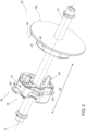
Figure 2 is a perspective view of a support device of the packaging machine ofFigure 1 , with parts removed for clarity; -
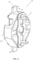
Figure 3 is an enlarged perspective view of a detail of the support device ofFigure 2 , with parts removed for clarity; -
Figure 4 is a front view of the detail ofFigure 2 , with parts removed for clarity; and -
Figures 5 to 7 are cross sections that illustrate the steps of coupling a reel to the support device ofFigure 2 , with parts removed for clarity. - Number 1 indicates as a whole a packaging machine for producing sealed packages 2 of a pourable product, in particular a pourable food product, such as milk, milk drinks, yoghurt, yoghurt drinks, fruit juice, wine, tomato sauce, emulsions, beverages containing pulp, salt, sugar, etc.
- In more detail, packaging machine 1 may be configured to produce packages 2 from a web of
packaging material 3, preferentially a web of multilayer packaging material. - More preferentially, web of
packaging material 3 may have heat seal properties (i.e. portions of the multilayer packaging material can be sealed to one another). - In further detail, web of
packaging material 3 may comprise at least one layer of fibrous material, such as e.g. paper or cardboard, and at least two layers of heat-seal plastic material, e.g. polyethylene, interposing the layer of fibrous material in between one another. Preferentially, one of these two layers of heat-seal plastic material may define the inner face of packages 2 contacting the pourable product. - Moreover, web of
packaging material 3 may also comprise a layer of gas- and light-barrier material, e.g. aluminum foil or ethylene vinyl alcohol (EVOH) film, preferentially being arranged between one of the layers of the heat-seal plastic material and the layer of fibrous material. - Preferentially, web of
packaging material 3 may also comprise a further layer of heat-seal plastic material being interposed between the layer of gas- and light-barrier material and the layer of fibrous material. - Preferentially, web of
packaging material 3 may comprise successively arranged patterns, each pattern defining a final graphical pattern of the respective package 2. In other words, packaging machine 1 operates, in use, such to guarantee that packages 2 comprise the respective pattern. - Furthermore, packaging machine 1 may be configured to produce packages 2 by forming a tube 4 from web of
packaging material 3, longitudinally sealing tube 4, filling tube 4 with the pourable product and to transversally seal, and preferentially transversally cut tube 4. - According to some possible non-limiting embodiments, each package 2 may extend along a longitudinal axis A.
- According to some possible embodiments, each package 2 may comprise at least a first
transversal sealing band 5a arranged at a first end of package 2, and preferentially also a secondtransversal sealing band 5b arranged at a second end of package 2 opposite to the first end. - Preferentially, each first
transversal sealing band 5a may be substantially spaced apart from the respective secondtransversal sealing band 5b along the respective longitudinal axis A. - Moreover, each package 2 may also comprise a longitudinal seam portion 6. Preferentially, each first
transversal sealing band 5a and/or each secondtransversal sealing band 5b may be transversal, preferentially perpendicular, to the respective longitudinal seam portion 6. - With particular reference to
Figure 1 , packaging machine 1 may comprise: - a
magazine unit 10 configured to host at least one,reel 11 of web ofpackaging material 3 at ahost station 12; and - a
conveying device 13 configured to advance web ofpackaging material 3 along a web advancement path P. - According to some preferred non-limiting embodiments, conveying
device 13 may be configured to advance web ofpackaging material 3 to atube forming station 14, at which, in use, web ofpackaging material 3 is formed into tube 4, and configured to advance tube 4 along a tube advancement path Q. - According to some preferred non-limiting embodiments, packaging machine 1 may also comprise:
- a tube forming and
sealing device 15 configured to form tube 4 from the, in use, advancing web ofpackaging material 3 and to longitudinally seal tube 4, preferentially attube forming station 14; - a
filling device 16 for filling tube 4 with the pourable product; and - a
package forming unit 17 configured to transversally seal, and preferentially to transversally cut tube 4 for obtaining semi-finalized packs, preferentially package pouches. Preferentially,package forming unit 17 may also be configured to form tube 4. - In further detail, packaging machine 1 may also comprise an
isolation chamber 18, preferentially delimiting aninner environment 19 from anouter environment 20. Preferentially,inner environment 19 may be a sterile environment, preferably containing a controlled atmosphere. - Preferentially, tube forming and sealing
device 15 may be at least partially arranged within and configured to fold and longitudinally seal tube 4 withinisolation chamber 18, preferentiallyinner environment 19. - Moreover, packaging machine 1 may also comprise a sterilizing unit configured to sterilize the, in use, advancing web of
packaging material 3, preferentially the sterilization unit being arranged upstream of tube forming and sealingdevice 15 along web advancement path P and/or downstream ofhost station 12. - In more detail, conveying
device 13 may be configured to advance tube 4 and any intermediates of tube 4 along tube advancement path Q, preferentially from tube forming and sealingdevice 15 to and/or at least partially withinpackage forming unit 17. Preferentially, with the wording intermediates of tube 4 any configuration of web ofpackaging material 3 is meant prior to obtaining the tube structure and after folding of web ofpackaging material 3 by tube forming and sealingdevice 15 has started. In other words, the intermediates of tube 4 are a result of the gradual folding of web ofpackaging material 3 so as to obtain tube 4, preferentially by overlapping the (longitudinal) edges of web ofpackaging material 3 with one another. - According to some possible non-limiting embodiments, tube forming and sealing
device 15 may be arranged such that tube 4 may have a vertical orientation. - Preferentially, filling
device 16 may comprise a fillingpipe 23 being configured to direct, in use, the pourable product into tube 4. Preferentially, fillingpipe 23 may, in use, be at least partially placed within tube 4 for feeding, in use, the pourable product into tube 4. - According to some preferred non-limiting embodiments,
package forming unit 17 may comprise a plurality of, operative devices, each one configured to manipulate, preferentially to at least partially form, to at least transversally seal and to transversally cut, tube 4 for obtaining packages 2. - With particular reference to
Figure 1 ,magazine unit 10 may be arranged upstream ofisolation chamber 18 and/or tube forming and sealingdevice 15 and/orpackaging forming unit 17. - With particular reference to
Figures 1 to 4 ,magazine unit 10 comprises at least onesupport device 25 configured to carry at least onereel 11. - In more detail, each
reel 11 may comprise atubular holder 26 and web ofpackaging material 3 being wound abouttubular holder 26. - Tubular holder may comprise a hollow body.
- More specifically,
tubular holder 26 may extend along a center axis B, and preferentially may have a cylindric shape. -
Support device 25 may engage withtubular holder 26 for carryingreel 11. - Additionally,
magazine unit 10 may comprise a support structure for rotatably carryingsupport device 25 and such that, in use,support device 25 and reel 11 may rotate about a rotation axis C so as to unwind web ofpackaging material 3 fromtubular holder 26. - In use, web of
packaging material 3 ofreel 11 gets exhausted. - In particular, an
exhausted reel 11 comprises at least itstubular holder 26. Possibly, anexhausted reel 11 may also comprise some (minor) remaining portions of web ofpackaging material 3. - Moreover,
support device 25 is removably coupled to support structure in order to loadsupport device 25 carrying anew reel 11 and to removesupport device 25 carrying an exhausted reel 11 (i.e. at least the respective tubular holder 26). - Preferentially, the support structure may allow to carry at least two
support devices 25, one next to the other, and each one carrying arespective reel 11. In particular, in use, one of thesupport devices 25 rotates about the respective rotation axis C, while theother support device 25 stands still waiting for a splicing action to be executed. In more detail, therotating support device 25 carries the web ofpackaging material 3 being used and thestationary support device 25 carries the new web ofpackaging material 3, which shall be spliced to the web ofpackaging material 3 being used before the web ofpackaging material 3 being used is completely exhausted. - In further detail, each
reel 11 may comprise twolateral surface portions 27, preferentially spaced apart along a first direction D1 substantially parallel to, preferentially parallel to, center axis B. - Preferentially, each
lateral surface portion 27 may be substantially perpendicular, in particular perpendicular, to center axis B. - Moreover, each
tubular holder 26 may comprise and extend between twolateral rims 28 opposite to one another. - Additionally, each
lateral rim 28 may delimit arespective opening 29 of therespective tubular holder 26. - In further detail,
lateral surface portions 27 are formed from the respectivelateral rims 28 and respective lateral edges of web ofpackaging material 3. - It must be noted that, in use, the amount of web of
packaging material 3 decreases with time and accordingly the extension of eachlateral surface portion 27 is reduced. It is clear that the extension oflateral rims 28 is not subject to any reductions in size, during use. - Additionally, each
reel 11 may comprise anouter face 30 being radially displaced from center axis B. Preferentially,outer face 30 may correspond to a face of web ofpackaging material 3, which once the respective packages 2 are formed, defines the outer surface of the respective packages 2. - Preferentially,
outer face 30 may comprise the successively arranged patterns. - With particular reference to
Figures 2 to 7 ,support device 25 comprises aspindle 31 extending along a longitudinal axis E, afirst clamping group 32 and asecond clamping group 33 connected to spindle 31 and configured to clampreel 11 between one another. - First clamping
group 32 andsecond clamping group 33 may be secured tospindle 31, in particular such thatfirst clamping group 32 andsecond clamping group 33 do not move, in use, alongspindle 31. - According to some possible non-limiting embodiments,
support device 25 may comprise securing elements configured to securefirst clamping group 32 and/orsecond clamping group 33 tospindle 31. Possibly, at least some or all securing elements may allow to be loosened so as to allow to modify the relative position offirst clamping group 32 and/orsecond clamping group 33 onspindle 31. - According to some preferred non-limiting embodiments,
first clamping group 32 andsecond clamping group 33 may be coaxial tospindle 31. - In particular,
first clamping group 32 andsecond clamping group 33 are configured to maintain a relative position ofreel 11 with regard tospindle 31, i.e., in use, during rotation ofreel 11 around rotation axis C, there is no lateral displacement ofreel 11 along a direction parallel to rotation axis C. - Advantageously,
first clamping group 32 may be configured to laterally engagereel 11, in particular the respectivelateral surface portion 27, from a first side andsecond clamping group 33 may be configured to laterally engagereel 11, in particular the respectivelateral surface portion 27, from a second side opposite to the first side. In other words,first clamping group 32 andsecond clamping group 33 may be configured to engagereel 11 from opposite sides thereof. - More specifically, each one of
first clamping group 32 andsecond clamping group 33 is configured to engage one respectivelateral surface portion 27 for clamping therespective reel 11. - In further detail,
first clamping group 32 andsecond clamping group 33 may be spaced apart from one another along a second direction D2 parallel to longitudinal axis E. - In particular, the distance between
first clamping group 32 andsecond clamping group 33 may be determined by the length oftubular holder 26. - Advantageously,
second clamping group 33 may comprise alocking device 34 configured to engage the second side ofreel 11, preferentially the respectivelateral surface portion 27. - In more detail, locking
device 34 may be controllable between: - an active configuration in which
locking device 34 is configured to engage the second side ofreel 11, preferentially the respectivelateral surface portion 27, for clampingreel 11 in cooperation withfirst clamping group 32; and - a rest configuration in which it is possible to introduce
second clamping group 33 into and movesecond clamping group 33 withintubular holder 26, preferentially during a coupling step during whichreel 11 is coupled to supportdevice 25 and an uncoupling step during whichreel 11 is uncoupled fromsupport device 25. - In particular, thanks to locking
device 34 it is possible to couplereel 11 to and uncouplereel 11 fromsupport device 25 without the need of dismountingsecond clamping group 33 fromspindle 31. - In
Figure 5 spindle 31 and reel 11 are not coupled to one another yet. Additionally, lockingdevice 34 is in the active configuration and it is not yet possible to introducesecond clamping group 33 intotubular holder 26. Therefore, an operatorcontrols locking device 34 in the rest configuration so that it is possible to introducesecond clamping group 33 intotubular holder 26 and to movesecond clamping group 33 within tubular holder 26 (seeFigure 6 ). At some point,second clamping group 33 exits fromtubular holder 26 and lockingdevice 34 is controlled again in the active configuration thereby guaranteeing thatsecond clamping group 33 andfirst clamping group 32clamp reel 11 between one another (seeFigure 7 ). By controlling again lockingdevice 34 in the rest configuration and by movingsecond clamping group 33 along the opposite direction it is possible to uncouplesupport device 25 and reel 11 from one another. - Moreover, movement of
second clamping group 33 withintubular holder 26 may occur by movingreel 11 and/or by movingsecond clamping group 33. - Additionally,
second clamping group 33 is moved by movingsupport device 25 as a whole. - According to some preferred non-limiting embodiments, locking
device 34 may be biased in the active configuration, i.e. lockingdevice 34 is controlled automatically in the active configuration. This ensures that during a coupling step and whilesecond clamping group 33 exits fromtubular holder 26, lockingdevice 34 automatically gets in the active configuration such thatreel 11 becomes clamped betweenfirst clamping group 32 andsecond clamping group 33. - With particular reference to
Figures 2 to 7 , lockingdevice 34 may comprise one or more, in particular at least two, more in particular exactly two, lockingelements 39, each one being movable between a respective extracted position (seeFigures 2 to 5 and7 ) and a respective retracted position (seeFigure 6 ). - Each locking
element 39 may be configured to laterally engagereel 11, preferentially the respectivelateral surface portion 27 when being in the extracted position and to laterally disengage fromreel 11, preferentiallylateral surface portion 27, when being in the retracted position. - Moreover, locking
device 34 may be controlled in the active configuration and the rest configuration with lockingelements 39 being in, respectively, the respective extracted positions and the respective retracted positions. - In further detail, locking
elements 39 may be displaced from one another along a direction transversal, more specifically perpendicular to, to longitudinal axis E and/orspindle 31. - In particular, locking
elements 39 may be opposite to one another with respect to longitudinal axis E and/orspindle 31. - According to some preferred non-limiting embodiments, a relative distance between locking
elements 39 is larger when lockingelements 39 are in the respective extracted positions than when lockingelements 39 are in the respective retracted positions. - With reference to the specific embodiment shown, a maximum distance between the outermost portions of locking
elements 39 may equal or may be smaller than an inner diameter oftubular holder 26 when lockingelements 39 are in the extracted positions and may be larger than the inner diameter oftubular holder 26 when lockingelements 39 are in the retracted positions. - Moreover, during control of locking
elements 39 from the respective extracted positions to the respective retractedpositions locking elements 39 move towards one another and during control of lockingelements 39 from the respective rest positions to the respective extractedpositions locking element 39 move away from one another. - According to some preferred non-limiting embodiments, each locking
element 39 linearly moves between the respective extracted position and the respective retracted position. - According to some preferred non-limiting embodiments, each locking
element 39 may be radially movable and/or movable along a direction transversal to spindle 31 and/or the longitudinal axis E between the respective extracted position and the respective retracted position. - According to some preferred non-limiting embodiments, each locking
element 39 may comprise arespective engagement surface 40 configured to engagereel 11 with therespective locking element 39 being positioned in the respective extracted position. - In particular, each
engagement surface 40 faces first clampinggroup 32. - With particular reference to
Figures 4 to 7 , lockingdevice 34 may further comprise one or more, in particular at least two, more in particular exactly two, biasingelements 41, each one being coupled to and/or interacting with onerespective locking element 39 and being configured to bias therespective locking element 39 in the extracted position. - In other words, biasing
elements 41 guarantee that lockingdevice 34 is kept in the respective active configuration. - Each biasing
element 41 may be elastically deformable.Biasing elements 41 may be, for example, springs. - According to some preferred non-limiting embodiments,
second clamping group 33 may comprise onerespective housing space 42 for each lockingelement 39. - Preferentially, each locking
element 39 may be linearly moveably arranged within therespective housing space 42. - More specifically, each
housing space 42 may be at least partially delimited by two sliding surfaces spaced apart from one another. Additionally, each lockingelement 39 comprises two lateral engagement surfaces, each one engaging one respective sliding surface. In particular, interaction between sliding surfaces and lateral engagement surfaces define the linear movement of lockingelements 39 when moving between the respective extracted position and the respective retracted positions. - According to some preferred non-limiting embodiments, locking
device 34 may comprise at least afirst control assembly 43, preferentially also asecond control assembly 44, coupled to lockingelements 39 and being configured to allow control of lockingelements 39 from the respective extracted positions to the respective retracted positions. - With particular reference to
Figures 2 to 7 ,first control assembly 43 andsecond control assembly 44 may be associated to opposite sides ofsecond clamping group 33. In particular, in this way,first control assembly 43 andsecond control assembly 44 are approachable from different sides, which is advantageous in order to render control of lockingelements 39 from the extracted positions to the retracted positions comfortable and independent on whetherreel 11 needs to be coupled or uncoupled fromsupport device 25. - When controlling
locking elements 39 from the extracted positions to the retracted positions for couplingreel 11 to supportdevice 25,second control assembly 44 needs to enter tubular holder 26 (see for exampleFigures 5 and6 ) and cannot be handled by an operator, wherebyfirst control assembly 43 is easily accessible and can be operated by an operator during insertion ofsecond clamping group 33 intotubular holder 26. On the other side, whenreel 11 is coupled to supportdevice 25,first control assembly 43 sits withintubular holder 26 and is not accessible, whilesecond control assembly 44 can be operated by an operator (seeFigure 7 ). - In particular, operation of
first control assembly 43 andsecond control assembly 44 allows to counter-act the force generated by biasingelements 41. - In further detail, each one of
first control assembly 43 andsecond control assembly 44 comprises tworespective control elements 45, each one integrally connected to onerespective locking element 39. -
Control elements 45 offirst control assembly 43 and ofsecond control assembly 44 are configured to be engaged by an operator so as to operate, respectively,first control assembly 43 andsecond control assembly 44. - According to some preferred non-limiting embodiments, each
control element 45 may axially protrude, e.g. from therespective locking element 39 as shown with regard to controlelements 45 offirst control assembly 43. - When reverting to
second control assembly 44 one notes that therespective control elements 45 are configured so as to define together with therespective locking elements 39 an indentation. - It is clear that the specific arrangements of
control elements 45 offirst control assembly 43 may be applied similarly bysecond control assembly 44 or vice versa. - According to some preferred non-limiting embodiments,
first clamping group 32 may comprise anengagement surface 46 configured to engagereel 11, preferentially the respectivelateral surface portion 27, for clampingreel 11 betweenengagement surface 46 andengagement surface 40. - In particular,
engagement surface 46 andengagement surface 40 may face one another. - With particular reference to
Figures 2 to 7 , each one offirst clamping group 32 andsecond clamping group 33 may comprise arespective support surface 47 configured to carrytubular holder 26. - More specifically, each
support surface 47 may comprise a plurality ofsurface portions 48, in the specific case shown four, angularly displaced from one another about longitudinal axis E. - Moreover, the
respective surface portions 48 may be equally and angularly spaced apart from one another about longitudinal axis E. - In the specific case shown, each
support surface 47 may be formed by discretely arrangedsurface portions 48. Alternatively, support surfaces 47 could have an annular shape. - In both cases,
support surface 47 lies on an annular imaginary surface, preferentially an imaginary cylinder. Preferentially, a size of the imaginary surface corresponds to an inner size oftubular holder 26. - More specifically, a radius of the imaginary surface corresponds to an inner radius of
tubular holder 26. - According to some preferred non-limiting embodiments, locking
elements 39 may be flush withsupport surface 47 when being placed in the retracted positions. - In use, packaging machine 1 forms packages 2 filled with the pourable product.
- In more detail, conveying
device 13 advances web ofpackaging material 3 frommagazine unit 10, preferentially tohost station 12. - In further detail, conveying
device 13 advances web ofpackaging material 3 from host station 7 to formingstation 10 at which web ofpackaging material 3 is formed into tube 4. During advancement of web ofpackaging material 3support device 25 rotates about rotation axis C. - Conveying
device 13 further advances tube 4 along tube advancement path Q to package formingunit 17. During advancement of tube 4, fillingdevice 16 fills tube 4 with the pourable product. - Preferentially, during advancement of web of
packaging material 3 along web advancement path P web ofpackaging material 3 is sterilized at the sterilization station. -
Package forming unit 13 forms and transversally seals tube 4 and, preferentially, also transversally cuts tube 4 so as to obtain packages 2. - Additionally, during operation, each
reel 11 gets exhausted. In order to avoid interruption of production, a new web ofpackaging material 3 is spliced to web ofpackaging material 3 being used. - Additionally, repeatedly one feeds
new reels 11 intomagazine unit 10. - Therefore, one needs to repeatedly couple
reels 11 to and uncouplereels 11 fromsupport device 25. - Such operations may be done outside of
magazine unit 10. - The method for coupling a
respective reel 11 to onerespective support device 25 comprises the steps of: - providing the
respective support device 25; and - supplying a
new reel 11 having therespective tubular holder 26 and the respective web ofpackaging material 3 wound about therespective tubular holder 26. - Additionally, the method comprises the steps of:
- controlling
locking device 34 in the rest configuration; - inserting
second clamping group 33, preferentially through arespective opening 29, intotubular holder 26; and - pushing
second clamping group 33 through and at least partially out oftubular holder 26, preferentially until lockingdevice 34 exits through theopposite opening 29; and - controlling
locking device 34 back to the active configuration after finishing to pushsecond clamping group 33 throughtubular holder 26, preferentially after exiting of lockingdevice 34 through theopposite opening 29. - In more detail, during the step of controlling
locking device 34 in the respective rest configuration, therespective locking elements 39 are moved in the respective retracted positions. More specifically,first control assembly 43 is operated so as to move lockingelements 39 in the retracted positions. - Moreover, during the step of inserting and the step of pushing, one moves
support device 25. Alternatively or in addition, one movesreel 11. - Typically, it is advisable to move
support device 25 asreel 11 has a significant weight. - Additionally, during the step of pushing, locking
elements 39 abut againsttubular holder 26, in particular an inner surface oftubular holder 26, and, therefore, cannot move back to the extracted positions. - According to some preferred non-limiting embodiments, during the step of controlling
locking device 34 back to the active configuration, biasingelements 41bias locking elements 39 back to the extracted positions. - Moreover, afterwards, reel 11 is clamped between
first clamping group 32 andsecond clamping group 33. - Then, one places
support device 25 together withreel 11 inmagazine unit 10. - Before complete exhaustion of web of
packaging material 3 being used, the new web ofpackaging material 3 of thenew reel 11 is spliced to the web ofpackaging material 3 in use. - Afterwards, one needs to remove the
exhausted reel 11 and eventually to place anew reel 11 withinmagazine unit 10. - Then one wants to uncouple at least the
respective tubular holder 26 fromsupport device 25. It may also occur that some remaining portions of web ofpackaging material 3 are still connected totubular holder 26. In such a case, one detaches tubular bolder 26 together with the remaining web ofpackaging material 3 fromsupport device 25. - The method for uncoupling
tubular holder 26 fromsupport device 25 comprises the steps of: - controlling
locking device 34 in the respective rest configuration; - forcing
second clamping group 33 intotubular holder 26, in particular through therespective opening 29; and - pushing
second clamping group 33 through and out oftubular holder 26. - In more detail, during the step of controlling
locking device 34 in the rest configuration, therespective locking elements 39 are moved in the respective retracted positions. More specifically,second control assembly 44 is operated so as to move lockingelements 39 in the retracted positions. - Once
second clamping group 33 has exited from therespective opening 29, lockingdevice 34 is biased back to the active configuration. - The advantages of
support device 25 according to the present invention will be clear from the foregoing description. - In particular,
support device 25 allows to couplereel 11 to and uncouple areel 11 fromsupport device 25 in an easy manner. - Additionally, by locking
device 34 being biased in the active configuration, one ensures clamping ofreel 11. - Moreover,
first control assembly 43 andsecond control assembly 44 allow an easy operation of lockingdevice 34 both when areel 11 is coupled to supportdevice 25 and when areel 11 needs to be coupled to supportdevice 25. - Clearly, changes may be made to packaging machine 1, and/or
support device 25 and/or the methods as described herein without, however, departing from the scope of protection as defined in the accompanying claims.
Claims (16)
- Support device (25) for carrying a reel (11) having a tubular holder (26) and a web of packaging material (3) wound about the tubular holder (26);wherein the support device (25) comprises a spindle (31) extending along a longitudinal axis (E), a first clamping group (32) and a second clamping group (33) connected to the spindle (31) and configured to clamp the reel (11) between one another;wherein the first clamping group (32) is configured to laterally engage the reel (11) from a first side and the second clamping group (33) is configured to laterally engage the reel (11) from a second side opposite to the first side;wherein the second clamping group (33) comprises a locking device (34) controllable between:- an active configuration in which the locking device (34) is configured to engage the second side of the reel (11) for clamping the reel (11) in cooperation with the first clamping group (32); and- a rest configuration in which it is possible to introduce the second clamping group (32) into the tubular holder (26) and to move the second clamping group (33) within the tubular holder (26).
- Support device according to claim 1, wherein the locking device (34) is biased in the active configuration.
- Support device according to claim 1 or 2 wherein the locking device (34) comprises one or more locking elements (39), each locking element (39) being movable between a respective extracted position and a respective retracted position;wherein each locking element (39) is configured to laterally engage the reel (11) when being in the extracted position and to laterally disengage from the reel (11) when being in the retracted position;wherein the locking device (34) is controlled in the active configuration and the rest configuration with each locking element (39) being in, respectively, the respective extracted position and the respective retracted position.
- Support device according to claim 3, wherein each locking element (39) is radially movable and/or movable along a direction transversal to the spindle (31) and/or the longitudinal axis (E) between the respective extracted position and the respective retracted position.
- Support device according to claim 3 or 4, wherein the locking device (34) further comprises one or more biasing elements (41), each biasing element (41) interacting with one respective locking element (39) and being configured to bias the respective locking element (39) in the extracted position.
- Support device according to any one of claims 3 to 5, wherein the second clamping group (33) comprises one respective housing space (42) for each locking element (39);
wherein each locking element (39) is linearly moveably arranged within the respective housing space (42). - Support device according to claim 6, wherein each housing space (42) is at least partially delimited by two sliding surfaces spaced apart from one another;
wherein each locking element (39) comprises two lateral engagement surfaces, each one engaging one respective sliding surface. - Support device according to any one of claims 3 to 7, wherein the locking device (34) comprises at least a first control assembly (43) coupled to the one or more locking elements (39) and being configured to allow control of the locking elements (39) from the respective extracted positions to the respective retracted positions.
- Support device according to claim 8, wherein the first control assembly (43) comprises two control elements (45), each one integrally connected to one respective locking element (39);
wherein each control element (45) is configured to be engaged by an operator so as to allow operation of the first control assembly (43). - Support device according to claim 9, wherein each control element (45) axially protrudes from the respective locking element (39).
- Support device according to any one of claims 8 to 10, and further comprising a second control assembly (44) coupled to the locking elements (39) and being configured to allow control of the locking elements (39) from the extracted position to the retracted position;
wherein the first control assembly (43) and the second control assembly (44) are associated to opposite sides of the second clamping group (44). - Support device according to any one of the preceding claims, wherein each one of the first clamping group (32) and the second clamping group (33) comprises a support surface (47) configured to carry the tubular holder (26) .
- Support device according to claim 12, wherein each support surface (47) comprises a plurality of surface portions (48) angularly displaced from one another about the longitudinal axis (E).
- A packaging machine (1) for producing sealed packages (2) of a pourable product comprising:- an isolation chamber (18) separating an inner environment (19) from an outer environment (20);- a tube forming and sealing device (15) at least partially arranged within the isolation chamber (18) and configured to form and longitudinally seal a tube (4) from a web of packaging material (3) at a tube forming station (14) ;- a filling device (16) for filling the tube (3) with the pourable product;- a package forming unit (17) configured to manipulate the tube (3) for forming the packages (2);- a conveying device (13) for advancing the web of packaging material (3) along a web advancement path (P) from a host station (12) to the tube forming station (14) and for advancing the tube (3) along a tube advancement path (Q) to the package forming unit (13); anda magazine unit (10) for storing at least one reel (11) having a tubular holder (26) and a web of packaging material (3) wound about the tubular holder (26);wherein the magazine unit (10) comprises at least one support device (25) according to any one of the preceding claims.
- Method for coupling a reel (11) to a support device (25) ;
the method comprising the steps of:- providing a support device (25) according to any one of claims 1 to 13;- supplying a reel (11) having a tubular holder (26) and a web of packaging material (3) wound about the tubular holder (26);- controlling the locking device (34) in the rest configuration;- inserting the second clamping group (33) into the tubular holder (26);- pushing the second clamping group (33) through the tubular holder (26); and- controlling the locking device (34) back to the active configuration after finishing to push the second clamping group (33) through and at least partially out of the tubular holder (26). - Method for uncoupling a tubular holder of an exhausted reel (11) from a support device (25) according to any one of claims 1 to 13;
the method comprising the steps of:- controlling the locking device (34) in the rest configuration;- forcing the second clamping group (33) into the tubular holder (26);- pushing the second clamping group (33) through and out of the tubular holder (26).
Applications Claiming Priority (1)
| Application Number | Priority Date | Filing Date | Title |
|---|---|---|---|
| IT102023000016953A IT202300016953A1 (en) | 2023-08-08 | 2023-08-08 | SUPPORTING DEVICE FOR A REEL, PACKAGING MACHINE HAVING A SUPPORTING DEVICE FOR A REEL, METHOD OF COUPLING A REEL TO A SUPPORTING DEVICE, AND METHOD OF UNCOUPLING A REEL FROM A SUPPORTING DEVICE |
Publications (1)
| Publication Number | Publication Date |
|---|---|
| EP4506288A1 true EP4506288A1 (en) | 2025-02-12 |
Family
ID=88290575
Family Applications (1)
| Application Number | Title | Priority Date | Filing Date |
|---|---|---|---|
| EP24184212.9A Pending EP4506288A1 (en) | 2023-08-08 | 2024-06-25 | Support device for a reel, packaging machine having a support device for a reel, method for coupling a reel to a support device and method for uncoupling a reel from a support device |
Country Status (4)
| Country | Link |
|---|---|
| EP (1) | EP4506288A1 (en) |
| CN (1) | CN121729372A (en) |
| IT (1) | IT202300016953A1 (en) |
| WO (1) | WO2025031660A1 (en) |
Citations (4)
| Publication number | Priority date | Publication date | Assignee | Title |
|---|---|---|---|---|
| DE850617C (en) * | 1948-10-10 | 1952-09-25 | Roto Werke A G | Paper roll storage for multipliers |
| DE2261559A1 (en) * | 1972-12-15 | 1974-06-20 | Windmoeller & Hoelscher | CARRYING SHAFT FOR GOOD COILED ON SLEEVES |
| WO2012107906A1 (en) * | 2011-02-11 | 2012-08-16 | Sidel S.P.A. Con Socio Unico | A unit for supporting and unwinding a reel of web material for a web processing machine |
| IT202100017951A1 (en) * | 2021-07-08 | 2023-01-08 | Elettroriolo Di Veggi Maurizio Flavio | HOLDER FOR ADHESIVE TAPE |
-
2023
- 2023-08-08 IT IT102023000016953A patent/IT202300016953A1/en unknown
-
2024
- 2024-06-25 CN CN202480052268.1A patent/CN121729372A/en active Pending
- 2024-06-25 EP EP24184212.9A patent/EP4506288A1/en active Pending
- 2024-06-25 WO PCT/EP2024/067762 patent/WO2025031660A1/en active Pending
Patent Citations (4)
| Publication number | Priority date | Publication date | Assignee | Title |
|---|---|---|---|---|
| DE850617C (en) * | 1948-10-10 | 1952-09-25 | Roto Werke A G | Paper roll storage for multipliers |
| DE2261559A1 (en) * | 1972-12-15 | 1974-06-20 | Windmoeller & Hoelscher | CARRYING SHAFT FOR GOOD COILED ON SLEEVES |
| WO2012107906A1 (en) * | 2011-02-11 | 2012-08-16 | Sidel S.P.A. Con Socio Unico | A unit for supporting and unwinding a reel of web material for a web processing machine |
| IT202100017951A1 (en) * | 2021-07-08 | 2023-01-08 | Elettroriolo Di Veggi Maurizio Flavio | HOLDER FOR ADHESIVE TAPE |
Also Published As
| Publication number | Publication date |
|---|---|
| IT202300016953A1 (en) | 2025-02-08 |
| CN121729372A (en) | 2026-03-24 |
| WO2025031660A1 (en) | 2025-02-13 |
Similar Documents
| Publication | Publication Date | Title |
|---|---|---|
| EP2246282B1 (en) | Method for moving a reel of packaging material from a storage station to a supply station of a packaging unit for producing sealed packages of food product, and clamping unit for clamping such reel | |
| US9073716B2 (en) | Method for feeding a supply station of a packaging unit with a new reel of sheet packaging material, sheet packaging material holder and lift truck | |
| CN113453987A (en) | Packaging machine and method for producing sealed packages | |
| US20200001518A1 (en) | Guiding device | |
| EP4032819B1 (en) | Infeed conveyor for a folding apparatus, folding apparatus having an infeed conveyor and packaging machine having a folding apparatus | |
| CN111655601A (en) | Cartridge unit for a packaging machine, packaging machine with a cartridge unit and method of operating a packaging machine | |
| CA2544441A1 (en) | Method for changing rolls of tubular film | |
| EP4265533A1 (en) | Infeed conveyor for a folding apparatus, folding apparatus having an infeed conveyor and packaging machine having a folding apparatus | |
| WO2025031660A1 (en) | Support device for a reel, packaging machine having a support device for a reel, method for coupling a reel to a support device and method for uncoupling a reel from a support device | |
| EP3517467B1 (en) | Magazine unit for a packaging machine, packaging machine having a magazine unit and method for loading a magazine unit | |
| CN111433007A (en) | Web alignment apparatus, packaging machine with web alignment apparatus and splicing method | |
| EP4527769A1 (en) | Magazine unit for a packaging machine, packaging machine having a magazine unit and method for loading a magazine unit | |
| EP4647380A1 (en) | Magazine apparatus for a packaging machine and packaging machine having a magazine apparatus | |
| EP4647378A1 (en) | Magazine apparatus for a packaging machine and packaging machine having a magazine apparatus | |
| EP4606749A1 (en) | Splicing unit for splicing a sealing strip of heat-sealable material, apparatus for applying a sealing strip to a web of packaging material and packaging machine for forming sealed packages | |
| EP4647379A1 (en) | Magazine apparatus for a packaging machine, packaging machine having a magazine apparatus and a packaging plant | |
| EP4588646A1 (en) | Apparatus for applying a sealing strip of a heat-sealable material to a web of packaging material and packaging machine for forming sealed packages | |
| EP4606751A1 (en) | Buffer unit of a web of packaging material for a packaging machine and packaging machine for forming sealed packages | |
| EP4474299A1 (en) | Package forming apparatus and packaging machine for forming packages | |
| EP4656538A1 (en) | Folding apparatus, packaging machine having a folding apparatus and method for forming finalized packages from semi-finalized packs | |
| CN120659752A (en) | Cartridge unit for a packaging machine, packaging machine with a cartridge unit and method for operating a cartridge unit of a packaging machine | |
| EP4656534A1 (en) | Infeed conveyor for a folding apparatus, folding apparatus having an infeed conveyor and packaging machine having a folding apparatus for forming finalized packages from semi-finalized packs | |
| EP4656539A1 (en) | Folding apparatus, packaging machine having a folding apparatus and method for forming finalized packages from semi-finalized packs | |
| HK1169090A (en) | Method for moving a reel of packaging material from a storage station to a supply station of a packaging unit for producing sealed packages of food product, and clamping unit for clamping such reel |
Legal Events
| Date | Code | Title | Description |
|---|---|---|---|
| PUAI | Public reference made under article 153(3) epc to a published international application that has entered the european phase |
Free format text: ORIGINAL CODE: 0009012 |
|
| STAA | Information on the status of an ep patent application or granted ep patent |
Free format text: STATUS: THE APPLICATION HAS BEEN PUBLISHED |
|
| AK | Designated contracting states |
Kind code of ref document: A1 Designated state(s): AL AT BE BG CH CY CZ DE DK EE ES FI FR GB GR HR HU IE IS IT LI LT LU LV MC ME MK MT NL NO PL PT RO RS SE SI SK SM TR |
|
| STAA | Information on the status of an ep patent application or granted ep patent |
Free format text: STATUS: REQUEST FOR EXAMINATION WAS MADE |
|
| 17P | Request for examination filed |
Effective date: 20250812 |
|
| GRAP | Despatch of communication of intention to grant a patent |
Free format text: ORIGINAL CODE: EPIDOSNIGR1 |
|
| STAA | Information on the status of an ep patent application or granted ep patent |
Free format text: STATUS: GRANT OF PATENT IS INTENDED |
|
| INTG | Intention to grant announced |
Effective date: 20260413 |