EP4506268A1 - Feeding unit for feeding semi-finished packs to a folding unit - Google Patents
Feeding unit for feeding semi-finished packs to a folding unit Download PDFInfo
- Publication number
- EP4506268A1 EP4506268A1 EP24184215.2A EP24184215A EP4506268A1 EP 4506268 A1 EP4506268 A1 EP 4506268A1 EP 24184215 A EP24184215 A EP 24184215A EP 4506268 A1 EP4506268 A1 EP 4506268A1
- Authority
- EP
- European Patent Office
- Prior art keywords
- packs
- pack
- feeding unit
- carrier
- station
- Prior art date
- Legal status (The legal status is an assumption and is not a legal conclusion. Google has not performed a legal analysis and makes no representation as to the accuracy of the status listed.)
- Pending
Links
Images


Classifications
-
- B—PERFORMING OPERATIONS; TRANSPORTING
- B65—CONVEYING; PACKING; STORING; HANDLING THIN OR FILAMENTARY MATERIAL
- B65B—MACHINES, APPARATUS OR DEVICES FOR, OR METHODS OF, PACKAGING ARTICLES OR MATERIALS; UNPACKING
- B65B35/00—Supplying, feeding, arranging or orientating articles to be packaged
- B65B35/10—Feeding, e.g. conveying, single articles
- B65B35/24—Feeding, e.g. conveying, single articles by endless belts or chains
-
- B—PERFORMING OPERATIONS; TRANSPORTING
- B65—CONVEYING; PACKING; STORING; HANDLING THIN OR FILAMENTARY MATERIAL
- B65B—MACHINES, APPARATUS OR DEVICES FOR, OR METHODS OF, PACKAGING ARTICLES OR MATERIALS; UNPACKING
- B65B61/00—Auxiliary devices, not otherwise provided for, for operating on sheets, blanks, webs, binding material, containers or packages
- B65B61/24—Auxiliary devices, not otherwise provided for, for operating on sheets, blanks, webs, binding material, containers or packages for shaping or reshaping completed packages
-
- B—PERFORMING OPERATIONS; TRANSPORTING
- B65—CONVEYING; PACKING; STORING; HANDLING THIN OR FILAMENTARY MATERIAL
- B65B—MACHINES, APPARATUS OR DEVICES FOR, OR METHODS OF, PACKAGING ARTICLES OR MATERIALS; UNPACKING
- B65B61/00—Auxiliary devices, not otherwise provided for, for operating on sheets, blanks, webs, binding material, containers or packages
- B65B61/28—Auxiliary devices, not otherwise provided for, for operating on sheets, blanks, webs, binding material, containers or packages for discharging completed packages from machines
-
- B—PERFORMING OPERATIONS; TRANSPORTING
- B65—CONVEYING; PACKING; STORING; HANDLING THIN OR FILAMENTARY MATERIAL
- B65B—MACHINES, APPARATUS OR DEVICES FOR, OR METHODS OF, PACKAGING ARTICLES OR MATERIALS; UNPACKING
- B65B35/00—Supplying, feeding, arranging or orientating articles to be packaged
- B65B35/10—Feeding, e.g. conveying, single articles
- B65B35/12—Feeding, e.g. conveying, single articles by gravity
Definitions
- the present invention relates to a feeding unit for feeding semi-finished packages containing a pourable product, preferably a pourable food product, to a folding unit.
- the present invention refers, without loss of generality, to a feeding unit configured to receive sealed semi-finished pillow packs containing a pourable product from a forming unit of a packaging machine and to feed such pillow packs to a folding unit for folding the pillow packs so as to obtain fully-folded finished packages.
- pourable food products such as fruit juice, UHT (ultra-high temperature-treated) milk, wine, tomato sauce, etc.
- UHT ultra-high temperature-treated milk
- wine tomato sauce
- etc. are sold in packages made of sterilized packaging material.
- a typical example is the parallelepiped-shaped package for pourable food products known as Tetra Brik Aseptic (registered trademark), which is made by folding and sealing a laminated web of packaging material.
- the packaging material has a multilayer structure comprising a base layer, e.g. made of paper, covered on both sides with layers of heat-seal plastic material, e.g. polyethylene.
- the packaging material also comprises a layer of oxygen-barrier material, e.g. an aluminum foil, which is superimposed on a layer of heat-seal plastic material, and is in turn covered with another layer of heat-seal plastic material forming the inner face of the package eventually contacting the food product.
- a layer of oxygen-barrier material e.g. an aluminum foil
- Packages of this sort are normally produced on fully automatic packaging machines, which form and fill the packages starting from a multilayer web of packaging material.
- a continuous tube is formed starting from the web of packaging material initially wound in a reel and fed through a plurality of unwinding rollers.
- the web of packaging material is sterilized in the packaging machine, e.g. by applying a chemical sterilizing agent, such as hydrogen peroxide solution, which, once sterilization is completed, is removed from the surfaces of the packaging material, e.g. evaporated by heating.
- a chemical sterilizing agent such as hydrogen peroxide solution
- the tube is fed continuously along a first direction, normally a straight vertical direction, is filled with the sterilized food product from above and is formed, sealed and subsequently cut along equally spaced transversal cross-sections extending along a second direction, normally a direction orthogonal to the first direction.
- the known packaging machines comprise a forming unit comprising forming devices configured to form the tube, so as to imprint to the tube an external shape corresponding to a precursor of the desired shape of the final package.
- the forming unit also comprises sealing devices configured to seal the tube at equally spaced cross-sections orthogonal to the tube advancement direction.
- a packaging machine of the above type comprises a pair of alternately movable forming and sealing jaws which carry the forming devices and the sealing devices and are controllable with a reciprocating movement in the first direction and in a third direction orthogonal to the first direction and the second direction to interact with the tube at successive portions thereof.
- pillow packs are obtained thereby, which have a longitudinal sealing band, a top transversal sealing band at a top end portion of the pack, and a bottom transversal sealing band at a bottom end portion of the pack.
- the pillow packs are then cut at the cross-sections to be separated from one another.
- Each pillow pack also comprises, for each top and bottom end portion, an elongated substantially rectangular fin which is formed by the respective transversal sealing band, and a pair of substantially triangular flaps laterally projecting from opposite sides of the respective end portion and defined by respective trapezoidal walls.
- the forming and sealing jaws are moved to be ready to grip another subsequent portion of the tube.
- the packaging machines of the above type typically further comprise an automatic folding unit arranged operatively downstream of the forming unit.
- the pillow packs are directed to the folding unit for the final folding thereof, thereby obtaining the fully-folded finished packages.
- a typical folding unit of the aforementioned type comprises a conveyor for advancing the pillow packs along a folding path, and a plurality of folding devices arranged in fixed positions relative to the folding path and configured to cooperate cyclically with the pillow packs to perform relative folding operations thereon, which are well-known and will not be detailed herein.
- a correct transferring and feeding of the pillow packs from the forming unit to the folding unit is critical for proper operation of the folding unit.
- the known packaging machines further comprise a feeding unit operatively interposed between the forming unit and the folding unit, and therefore configured to receive the pillow packs from the forming unit and to feed and direct the pillow packs to the folding unit.
- the pillow packs are usually formed and sealed with their respective axes arranged vertically.
- the newly formed pillow packs are subsequently cut from the tube and let slide (by gravity) along a curved-profile chute arranged below the forming unit, so as to be brought from the vertical position to a substantially horizontal position, in which position they are received by the feeding unit.
- the feeding unit is arranged immediately downstream of the chute and immediately upstream of the folding unit.
- the feeding unit comprises two support guides extending between an input station, at which the pillow packs coming from the chute are received, and an output station, at which the pillow packs are delivered to the folding unit.
- the feeding unit further comprises an endless conveyor belt and a plurality of carriers, or push members, mounted on the conveyor belt at equidistant positions along the conveyor belt. By moving the belt, the carriers are conveyed along a closed-loop path.
- Each carrier projects from the conveyor belt outwardly and is configured to cooperate in contact with a respective pillow pack to advance the pillow pack from the input station to the output station by means of the movement of the belt, while the pillow pack is supported from below by the support guides.
- each carrier is configured to push a respective pillow pack from behind, i.e. at the bottom end portion of the pillow pack, so as to drive it along the guides.
- the endless belt is expediently wound about a system of pulleys and is driven by a known actuator.
- the closed-loop path has therefore a work section and a return section.
- the carriers conveyed along the work section push respective pillow packs, advancing them towards and up to the folding unit; the carriers conveyed along the return section are moved from the outlet station back to the inlet station, at which they are ready to interact with new respective pillow packs.
- the folding unit is synchronized with the carriers, which ideally must remain in contact with the bottom end portion of the pillow packs throughout the advancement and up to the output station, in order to correctly deliver the packs in a synchronized manner.
- each carrier on the respective pillow pack can cause a sort of forward bouncing of the pillow pack along the working section of the closed-loop path, especially at the very high speeds at which the packaging machine operates and due to the pourable product inertia within the pillow pack.
- the known feeding units are provided with braking/slowing devices for limiting such forward bouncing.
- spring-actuated plate members which are arranged along the work section, in a position over the support guides. Each plate member is biased downwardly in the direction of the pillow packs advanced by the carriers, so as to cooperate in contact with a wall of the pillow packs. The interaction with the plate member slows down the pillow packs, limiting the forward movement caused by the aforementioned bouncing.
- the known feeding units are still open to further improvement, in particular as per the improvement of the synchronization between the feeding unit and the folding unit, the lifespan of the components of the feeding unit, the flexibility of the feeding unit and the overall reliability of the feeding unit.
- number 1 indicates as a whole a non-limiting example of a packaging machine for producing a plurality of packages 2a containing a pourable product, preferably a pourable food product such as pasteurized or UHT milk, water, fruit juice, wine, peas, beans, etc.
- a pourable food product such as pasteurized or UHT milk, water, fruit juice, wine, peas, beans, etc.
- packaging machine 1 is configured to form, seal and fold packages 2a starting from a tube 3 of packaging material.
- the packaging material has a multilayer structure (not shown), and comprises a layer of fibrous material, e.g. paper, covered on both sides with respective layers of heat-seal plastic material, e.g. polyethylene.
- a layer of fibrous material e.g. paper
- heat-seal plastic material e.g. polyethylene
- the packaging material also comprises a layer of gas-and-light barrier material, e.g. aluminum foil or ethylene vinyl alcohol (EVOH) film, which is superimposed on a layer of heat-seal plastic material, and is in turn covered with another layer of heat-seal plastic material, the latter forming the inner face of package 2a eventually contacting the pourable product.
- gas-and-light barrier material e.g. aluminum foil or ethylene vinyl alcohol (EVOH) film
- the packaging material is initially provided in form of a web 4.
- the packaging machine 1 comprises:
- packaging machine 1 is configured to form and seal a plurality of pillow packs 2 containing the pourable product starting from web 4 and tube 3 and then to fold the pillow packs 2 for obtaining the aforementioned formed, sealed and folded packages 2a containing the pourable product.
- a non-limiting embodiment of a pillow pack 2 is depicted, which has a longitudinal sealing band 30 formed to produce the tube 3 from the web of packaging material folded into a cylinder and extending along one side of pack 2.
- Pack 2 is closed at opposite distal ends by a first transversal sealing band 31 and a second transversal sealing band 32, both perpendicular and joined to the longitudinal sealing band 30.
- Each pack 2 has an axis B and comprises a main portion 33, which extends along axis B and defines a main body, a first end portion 34, in particular a top end portion, and a second end portion 35, in particular a bottom end portion; first end portion 34 and second end portion 35 project and taper from opposite axial sides of main portion 33 towards the first sealing band 31 and the second sealing band 32, respectively.
- First end portion 34 comprises a substantially elongated end fin 36, formed by first transversal sealing band 31 and projecting along axis B, and two substantially triangular flaps (top flaps 37), projecting laterally on opposite sides of main portion 33.
- second end portion 35 comprises a substantially elongated end fin 38, formed by second transversal sealing band 32 and projecting along axis B, and two substantially triangular flaps (bottom flaps 39), projecting laterally on opposite sides of main portion 33.
- Packaging machine 1 further comprises at least one feeding unit 7 operatively interposed between the forming and sealing unit and folding unit 6.
- feeding unit 7 is configured to receive packs 2 from the forming and sealing unit and to feed such packs 2 to folding unit 6.
- folding unit 6 is of the known type and it will not be described in detail herein.
- folding unit 6 comprises an inlet region IR at which the folding unit 6 receives packs 2 from the feeding unit 7.
- Folding unit 6 may comprise a conveying device 6a, in particular a rotary conveying device, and configured to advance packs 2 through a folding path (not shown) along which the packs 2 are folded by known folding devices.
- conveying device 6a comprises a rotating wheel for advancing packs 2 along the above-mentioned folding path, and a plurality of said folding devices arranged in fixed positions relative to the folding path and configured to cooperate cyclically with packs 2 to perform relative folding operations thereon, which are well-known and will not be detailed herein.
- feeding unit 7 comprises:
- conveyor device 8 comprises a flexible endless belt element 11 wound about a number of pulleys 12, at least one of which is actuatable in rotation for determining the movement of belt element 11 along a closed-loop path P.
- Carrier members 10, which are fixed on belt element 11, are thereby conveyed along such closed-loop path P.
- carrier members 10 are conveyed along closed-loop path P.
- Each carrier member 10 projects from belt element 11 outwardly.
- Carrier members 10 are configured to cooperate in contact with packs 2 for sequentially advancing packs 2 from input station I to output station O.
- feeding unit 7 further comprises a chute member 13 interposed between the forming and sealing unit and conveyor member 8 and configured to receive formed and sealed packs 2 from the forming and sealing unit and to feed such packs 2 to conveyor device 8 at input station I.
- a chute member 13 interposed between the forming and sealing unit and conveyor member 8 and configured to receive formed and sealed packs 2 from the forming and sealing unit and to feed such packs 2 to conveyor device 8 at input station I.
- chute 13 feeds, in use, a sequence of packs 2 to conveyor device 8 by means of gravity. Hence, packs 2 which have been cut from tube 3 slide along chute 13 and reach conveyor device 8, at input station I.
- conveyor device 8 further comprises a pair of support guides 14 for supporting the packs 2 fed from chute 13 and advanced by carrier members 10, and for guiding such packs 2 from input station I to output station O.
- support guides 14 include a pair of substantially parallel guide rails extending at least from input station I to output station O and on which packs 2 are configured to slide while advanced by carrier members 10. In practice, support guides 14 receive, in use, packs 2 from chute 13 and support such packs 2 during their movement towards outlet station O.
- support guides 14 are configured to support packs 2 from below.
- packs 2 are supported by, i.e. rest on, support guides 14 in a sliding manner, without contacting belt element 11, while carrier members 10 cooperate in contact with packs 2 for advancing them, by means of a pushing action thereon.
- closed-loop path P comprises a work section W, which extends from input station I to output station O and along which packs 2 are conveyed, and a return section R, which extends from output station O to input station I and along which carrier members 10 return to input station I after having released the respective packs 2 to folding unit 6.
- the plurality of carrier members 10 comprises pairs of carrier members 10, each pair of carrier members 10 being configured to cyclically interact (i.e. cooperate in contact) with at least one respective pack 2 at a time, preferably with a single pack 2 at a time, for receiving such pack 2 at input station I and advancing such pack 2 towards output station O.
- the pair of carrier members 10 includes:
- leading carrier 10a and trailing carrier 10b define a (longitudinal) space between them for receiving and advancing packs 2.
- leading carrier 10a is configured to cooperate in contact with first end portion 34, i.e. top end portion 34
- trailing carrier 10b is configured to cooperate in contact with second end portion 35, i.e. bottom end portion 35.
- trailing carrier 10b driven by belt element 11, is configured to push pack 2 from behind until pack 2 is released to folding unit 6 at output station O.
- leading carrier 10a defines an abutment member for interacting, at input station I, with top end portion 34 of the pack 2 received thereat, whereas trailing carrier 10b defines a pushing member for interacting, between input station I and output station O, with bottom end portion 35 of such pack 2.
- leading carrier 10a is configured to stop respective packs 2 fed from chute member 13 at input station I.
- leading carrier 10a is configured to interact with top end portion 34 of each pack 2 for stopping a movement of such packs 2 along support guides 14, i.e. along work section W, i.e. towards output station O.
- pack 2 slides on chute member 13 and slidingly falls onto support guides 14 and is received within the space delimited by the respective pair of carrier members 10, which is opportunely transiting at input station I.
- pulleys 12 are controllable (e.g. by means of a known control unit) so as to synchronize the movement of belt element 11 with the action of forming and sealing unit, for allowing pack 2 to be correctly received in the aforementioned space between leading carrier 10a and trailing carrier 10b, at input station I.
- pack 2 slides along support guides 14, until it abuts against leading carrier 10a, which in the meantime is advancing along work section W conveyed by belt element 11. Normally, the relative speed of the falling pack 2 is greater than the speed of carrier members 10 along closed-loop path P.
- the pair of carrier members 10 is conveyed along return section R and again up to input station I, wherein the cycle repeats.
- leading carrier 10a and trailing carrier 10b are adjustable to fit several kinds of packs 2. In this way, format changes are more rapid, thereby increasing the flexibility of feeding unit 7 and packaging machine 1.
- conveyor device 8 comprises a braking device 15 configured to cooperate in contact with packs 2 for slowing packs 2 down along a braking path Q extending along part of work section W.
- braking device 15 comprises a pair of rail members 16 extending along braking path Q.
- rail members 16 are configured to cooperate in contact with top flaps 37 and bottom flaps 39 of pack 2 (as schematically shown in Figure 5 ), in order to slow down pack 2 along braking path Q.
- rail members 16 are configured to slow down pack 2 along braking path Q by means of friction on pack 2.
- rail members 16 are convergent towards one another in direction of output station O.
- rail members 16 are closer and closer to one another along braking path Q and with respect to a direction extending from input station I to output station O.
- This convergency of rail members 16 causes, in use, an increasing friction action on pack 2 advanced along braking path Q, thereby slowing pack 2 down by means of friction in a more precise and accurate manner.
- the convergence of rail members 16 determines a narrower and narrower passage for pack 2 to pass through, thereby increasing the friction on pack 2 and slowing pack 2 down.
- braking device 15 allows for further reducing the forward bouncing phenomenon ensuring that pack 2 stays as close as possible to trailing carrier 10b, and in particular ensuring that pack 2 stays in contact with trailing carrier 10b as long as possible, ultimately further improving the synchronization with folding unit 6.
- braking device 15 according to the invention has reduced wear, is very reliable, easily settable and highly flexible.
- both rail members 16 and support guides 14 extend along at least part of work section W.
- rail members 16 are arranged in a position above support guides 14 ( Figure 5 ).
- support guides 14 support packs 2 from below
- rail members 16 interact with packs 2 laterally and from above.
- rail members 16 are arranged with respect to support guides 14 so that each rail member 16 and each support guide 14 delimit together an elongated slot or channel or passage apt to receive and be engaged by said flaps 37, 39 during the advancement of pack 2 from input station I to output station O, so that flaps 37, 39 slidingly rest on support guides 14 and rail members 16 overlap at least partially flaps 37, 39.
- each rail member 16 and the corresponding support guide 14 arranged below it delimit together a respective elongated slot 17.
- rail members 16 and support guides 14 define two slots 17 extending along braking path Q.
- pack 2 when pack 2 is advanced by trailing carrier 10b along braking path Q, its 37, 39 (both left and right ones) slidably engage slots 17.
- flaps 37, 39 are slidably contained within slots 17, respectively.
- each rail member 16 advantageously includes ( Figures 3 and 4 ):
- second portion 16b at inlet region IR allows for preventing the aforementioned shuddering and sudden upward movement of pack 2 during releasing of such pack 2 at outlet station O.
- second portion 16b is separated from first portion 16a by a non-zero distance.
- first portion 16a and second portion 16b are spaced apart by means of an opening 18 configured to be engaged by the flaps proximal to the second end portion, i.e. by bottom flaps 39.
- bottom flaps 39 are configured to pass through the respective opening 18 to allow folding unit 6 to remove the respective pack 2 from feeding unit 7.
- each support guide 14 comprises, and particularly is defined by, a guide rail.
- each guide rail has a slanted surface 14a configured to support flaps 37, 39 in a sliding manner and which is slanted towards the other guide rail ( Figure 5 ) .
- each rail member 16 may have a slanted surface configured to support flaps 37, 39 in a sliding manner and which is slanted towards the other rail member 16.
- This configuration provides for less friction on packs 2, and therefore entails a reduced wear and damages of packs 2.
- support guides 14 may extend beyond output station O and up to inlet region IR.
- each pack 2 is also supported beyond output station O and up to inlet region IR.
- a sort of sudden "jump" of pack 2 from output station O to inlet region IR is thereby avoided, resulting in a better positioning of pack 2 in conveying device 6a and, ultimately, in a better folding of pack 2.
- feeding unit 7 will be described hereinafter, with reference to an initial condition in which a pack 2 slides along chute 13 and is received by a pair of carrier members 10 at input station I.
- pack 2 slides on support guides 14 until reaching leading carrier 10a, which is in turn advancing along work section W with a speed less than the speed of the falling pack 2. Pack 2 then abuts against leading carrier 10a and temporarily stops, until reached by trailing carrier 10b.
- trailing carrier 10b engages pack 2 and pushes pack 2 along work section W and up to output station O.
- flaps 37, 39 of pack 2 engage slots 17 and interact with rail members 16 of braking device 15.
- pack 2 is slowed down along braking path Q, thereby ensuring a lasting and stable contact between pack 2 and trailing carrier 10b.
- trailing carrier 10b releases pack 2 at output station O and towards inlet region IR, at which pack 2 is taken by conveying device 6a of folding unit 6.
- trailing carrier 10b and leading carrier 10a are advanced along return section R by belt element 11, up to input station I at which the cycle repeats.
- feeding unit 7 According to the present invention will be clear from the foregoing description.
- the feeding unit 7 allows a precise synchronization with folding unit 6 and is characterized by a significant lifespan of its components, especially the one of braking device 15.
- braking device 15 allows for further reducing the forward bouncing phenomenon ensuring that pack 2 stays in contact with trailing carrier 10b as long as possible, ultimately further improving the synchronization with folding unit 6.
- braking device 15 according to the invention is subjected to limited wear, and is reliable, easily settable and very flexible.
Landscapes
- Engineering & Computer Science (AREA)
- Mechanical Engineering (AREA)
- Auxiliary Devices For And Details Of Packaging Control (AREA)
Abstract
There is described a feeding unit (7) for feeding semifinished sealed packs (2) containing a pourable product to a folding unit (6) configured to fold the packs (2) so as to obtain folded packages (2a), the feeding unit (7) comprises: a conveyor device (8) having an input station (I) for receiving the packs (2) and an output station (O) for releasing the packs (2) to the folding unit (6); a plurality of carrier members (10) mounted on the conveyor device (8) for being cyclically carried through the input station (I) and output station (O), the carrier members (10) being configured to cooperate in contact with the packs (2) for sequentially advancing the packs (2) from the input station (I) to the output station (O); the plurality of carrier members (10) comprises pairs (10a, 10b) of carrier members (10), each pair (10a, 10b) of carrier members (10) being configured to interact with at least one respective pack (2) at a time for receiving such pack (2) at the input station (I) and for advancing such pack (2) towards the output station (O).
Description
- The present invention relates to a feeding unit for feeding semi-finished packages containing a pourable product, preferably a pourable food product, to a folding unit.
- In particular, the present invention refers, without loss of generality, to a feeding unit configured to receive sealed semi-finished pillow packs containing a pourable product from a forming unit of a packaging machine and to feed such pillow packs to a folding unit for folding the pillow packs so as to obtain fully-folded finished packages.
- As it is generally known, many pourable food products, such as fruit juice, UHT (ultra-high temperature-treated) milk, wine, tomato sauce, etc., are sold in packages made of sterilized packaging material.
- A typical example is the parallelepiped-shaped package for pourable food products known as Tetra Brik Aseptic (registered trademark), which is made by folding and sealing a laminated web of packaging material. The packaging material has a multilayer structure comprising a base layer, e.g. made of paper, covered on both sides with layers of heat-seal plastic material, e.g. polyethylene.
- In the case of aseptic packages for long-storage products, such as UHT milk, the packaging material also comprises a layer of oxygen-barrier material, e.g. an aluminum foil, which is superimposed on a layer of heat-seal plastic material, and is in turn covered with another layer of heat-seal plastic material forming the inner face of the package eventually contacting the food product.
- Packages of this sort are normally produced on fully automatic packaging machines, which form and fill the packages starting from a multilayer web of packaging material.
- In particular, in such packaging machines a continuous tube is formed starting from the web of packaging material initially wound in a reel and fed through a plurality of unwinding rollers. The web of packaging material is sterilized in the packaging machine, e.g. by applying a chemical sterilizing agent, such as hydrogen peroxide solution, which, once sterilization is completed, is removed from the surfaces of the packaging material, e.g. evaporated by heating. The web so sterilized is then maintained in a closed, sterile environment, and, being advanced by the aforementioned unwinding rollers, is folded and sealed longitudinally to form the tube by means of a known web folding unit.
- The tube is fed continuously along a first direction, normally a straight vertical direction, is filled with the sterilized food product from above and is formed, sealed and subsequently cut along equally spaced transversal cross-sections extending along a second direction, normally a direction orthogonal to the first direction.
- In order to perform the forming and sealing operations, the known packaging machines comprise a forming unit comprising forming devices configured to form the tube, so as to imprint to the tube an external shape corresponding to a precursor of the desired shape of the final package. The forming unit also comprises sealing devices configured to seal the tube at equally spaced cross-sections orthogonal to the tube advancement direction.
- Generally, a packaging machine of the above type comprises a pair of alternately movable forming and sealing jaws which carry the forming devices and the sealing devices and are controllable with a reciprocating movement in the first direction and in a third direction orthogonal to the first direction and the second direction to interact with the tube at successive portions thereof.
- So-called pillow packs are obtained thereby, which have a longitudinal sealing band, a top transversal sealing band at a top end portion of the pack, and a bottom transversal sealing band at a bottom end portion of the pack. The pillow packs are then cut at the cross-sections to be separated from one another.
- Each pillow pack also comprises, for each top and bottom end portion, an elongated substantially rectangular fin which is formed by the respective transversal sealing band, and a pair of substantially triangular flaps laterally projecting from opposite sides of the respective end portion and defined by respective trapezoidal walls.
- Once the cutting operation is completed, the forming and sealing jaws are moved to be ready to grip another subsequent portion of the tube.
- The packaging machines of the above type typically further comprise an automatic folding unit arranged operatively downstream of the forming unit.
- Once cut at their transversal sealing bands, the pillow packs are directed to the folding unit for the final folding thereof, thereby obtaining the fully-folded finished packages.
- A typical folding unit of the aforementioned type comprises a conveyor for advancing the pillow packs along a folding path, and a plurality of folding devices arranged in fixed positions relative to the folding path and configured to cooperate cyclically with the pillow packs to perform relative folding operations thereon, which are well-known and will not be detailed herein.
- A correct transferring and feeding of the pillow packs from the forming unit to the folding unit is critical for proper operation of the folding unit.
- To this end, the known packaging machines further comprise a feeding unit operatively interposed between the forming unit and the folding unit, and therefore configured to receive the pillow packs from the forming unit and to feed and direct the pillow packs to the folding unit.
- Within the forming unit, the pillow packs are usually formed and sealed with their respective axes arranged vertically. The newly formed pillow packs are subsequently cut from the tube and let slide (by gravity) along a curved-profile chute arranged below the forming unit, so as to be brought from the vertical position to a substantially horizontal position, in which position they are received by the feeding unit.
- In practice, the feeding unit is arranged immediately downstream of the chute and immediately upstream of the folding unit.
- Typically, the feeding unit comprises two support guides extending between an input station, at which the pillow packs coming from the chute are received, and an output station, at which the pillow packs are delivered to the folding unit.
- The feeding unit further comprises an endless conveyor belt and a plurality of carriers, or push members, mounted on the conveyor belt at equidistant positions along the conveyor belt. By moving the belt, the carriers are conveyed along a closed-loop path.
- Each carrier projects from the conveyor belt outwardly and is configured to cooperate in contact with a respective pillow pack to advance the pillow pack from the input station to the output station by means of the movement of the belt, while the pillow pack is supported from below by the support guides.
- In practice, each carrier is configured to push a respective pillow pack from behind, i.e. at the bottom end portion of the pillow pack, so as to drive it along the guides.
- The endless belt is expediently wound about a system of pulleys and is driven by a known actuator. The closed-loop path has therefore a work section and a return section. The carriers conveyed along the work section push respective pillow packs, advancing them towards and up to the folding unit; the carriers conveyed along the return section are moved from the outlet station back to the inlet station, at which they are ready to interact with new respective pillow packs.
- It is known the need for correctly synchronizing the advancement of the pillow packs on the feeding unit with the folding unit. More specifically, pillow packs must be fed to the folding unit with a specific and predetermined rate, in order to avoid jams, malfunctions and damages. To this end, the folding unit is synchronized with the carriers, which ideally must remain in contact with the bottom end portion of the pillow packs throughout the advancement and up to the output station, in order to correctly deliver the packs in a synchronized manner.
- It has been observed that the pushing action of each carrier on the respective pillow pack can cause a sort of forward bouncing of the pillow pack along the working section of the closed-loop path, especially at the very high speeds at which the packaging machine operates and due to the pourable product inertia within the pillow pack.
- To this end, the known feeding units are provided with braking/slowing devices for limiting such forward bouncing.
- For example, spring-actuated plate members are known which are arranged along the work section, in a position over the support guides. Each plate member is biased downwardly in the direction of the pillow packs advanced by the carriers, so as to cooperate in contact with a wall of the pillow packs. The interaction with the plate member slows down the pillow packs, limiting the forward movement caused by the aforementioned bouncing.
- In this way, the distance between each carrier and the respective pillow pack is maintained as small as possible during the advancement of the pillow pack towards the output station. Thus, the synchronization between the pillow packs and the folding unit is maintained optimal.
- Although being structurally and functionally valid, the known feeding units are still open to further improvement, in particular as per the improvement of the synchronization between the feeding unit and the folding unit, the lifespan of the components of the feeding unit, the flexibility of the feeding unit and the overall reliability of the feeding unit.
- It is therefore an object of the present invention to provide a feeding unit for feeding semi-finished packs to a folding unit, which is designed to meet at least one of the above-mentioned needs in a straightforward and low-cost manner.
- This object is achieved by a feeding unit as claimed in
claim 1. - A non-limiting embodiment of the present invention will be described by way of example with reference to the accompanying drawings, in which:
-
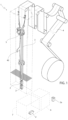
Figure 1 is a schematic perspective view of a packaging machine including a feeding unit according to the present invention, with parts removed for clarity; -
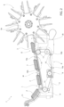
Figure 2 is a lateral view of the feeding unit according to the present invention, with parts removed for clarity; -
Figures 3 and4 are larger-scale, perspective views, with parts removed for clarity, of part of the feeding unit ofFigure 2 during two successive distinct operative conditions; -
Figure 5 is a larger-scale, schematic view from behind, with parts removed for clarity, of part of the feeding unit ofFigure 2 ; and -
Figure 6 is a perspective view of a semi-finished pack to be handled by the feeding unit according to the present invention. - With reference to
Figure 1 ,number 1 indicates as a whole a non-limiting example of a packaging machine for producing a plurality ofpackages 2a containing a pourable product, preferably a pourable food product such as pasteurized or UHT milk, water, fruit juice, wine, peas, beans, etc. - In detail,
packaging machine 1 is configured to form, seal andfold packages 2a starting from a tube 3 of packaging material. - Preferably, the packaging material has a multilayer structure (not shown), and comprises a layer of fibrous material, e.g. paper, covered on both sides with respective layers of heat-seal plastic material, e.g. polyethylene.
- In the case of
aseptic packages 2a for long-storage products, such as UHT milk, the packaging material also comprises a layer of gas-and-light barrier material, e.g. aluminum foil or ethylene vinyl alcohol (EVOH) film, which is superimposed on a layer of heat-seal plastic material, and is in turn covered with another layer of heat-seal plastic material, the latter forming the inner face ofpackage 2a eventually contacting the pourable product. - Preferably, the packaging material is initially provided in form of a
web 4. - As schematically shown in
Figure 1 , thepackaging machine 1 comprises: -
tube folding devices 5 for progressively folding theweb 4 into tube 3, in a manner known and not described in detail; - a sealing
element 40 for longitudinally sealing tube 3; - a filling device (not shown) for filling tube 3 with the pourable product;
- a forming and sealing unit (known per se and not shown) for forming and sealing tube 3, thereby obtaining a plurality of pillow packs 2, according to a manner known and not described in detail; and
- a folding unit 6 (only schematically shown) for folding the pillow packs 2, thereby obtaining the
packages 2a, according to a manner known and not described in detail. - Hence,
packaging machine 1 is configured to form and seal a plurality of pillow packs 2 containing the pourable product starting fromweb 4 and tube 3 and then to fold the pillow packs 2 for obtaining the aforementioned formed, sealed and foldedpackages 2a containing the pourable product. - With reference to
Figure 6 , a non-limiting embodiment of apillow pack 2 is depicted, which has alongitudinal sealing band 30 formed to produce the tube 3 from the web of packaging material folded into a cylinder and extending along one side ofpack 2.Pack 2 is closed at opposite distal ends by a firsttransversal sealing band 31 and a secondtransversal sealing band 32, both perpendicular and joined to thelongitudinal sealing band 30. - Each
pack 2 has an axis B and comprises amain portion 33, which extends along axis B and defines a main body, afirst end portion 34, in particular a top end portion, and asecond end portion 35, in particular a bottom end portion;first end portion 34 andsecond end portion 35 project and taper from opposite axial sides ofmain portion 33 towards thefirst sealing band 31 and thesecond sealing band 32, respectively. -
First end portion 34 comprises a substantiallyelongated end fin 36, formed by firsttransversal sealing band 31 and projecting along axis B, and two substantially triangular flaps (top flaps 37), projecting laterally on opposite sides ofmain portion 33. - Similarly,
second end portion 35 comprises a substantiallyelongated end fin 38, formed by second transversal sealingband 32 and projecting along axis B, and two substantially triangular flaps (bottom flaps 39), projecting laterally on opposite sides ofmain portion 33. -
Packaging machine 1 further comprises at least onefeeding unit 7 operatively interposed between the forming and sealing unit andfolding unit 6. - In detail, feeding
unit 7 is configured to receivepacks 2 from the forming and sealing unit and to feedsuch packs 2 tofolding unit 6. -
Folding unit 6 is of the known type and it will not be described in detail herein. Briefly,folding unit 6 comprises an inlet region IR at which thefolding unit 6 receivespacks 2 from thefeeding unit 7.Folding unit 6 may comprise a conveying device 6a, in particular a rotary conveying device, and configured to advancepacks 2 through a folding path (not shown) along which thepacks 2 are folded by known folding devices. In the embodiment disclosed, conveying device 6a comprises a rotating wheel for advancingpacks 2 along the above-mentioned folding path, and a plurality of said folding devices arranged in fixed positions relative to the folding path and configured to cooperate cyclically withpacks 2 to perform relative folding operations thereon, which are well-known and will not be detailed herein. - As shown in
Figure 2 , feedingunit 7 comprises: - a
conveyor device 8 having an input station I for sequentially receivingpacks 2 and an output station O for releasingpacks 2 tofolding unit 6; and - a plurality of
carrier members 10 mounted onconveyor device 7 for being cyclically conveyed through input station I and output station O. - In the embodiment shown,
conveyor device 8 comprises a flexibleendless belt element 11 wound about a number ofpulleys 12, at least one of which is actuatable in rotation for determining the movement ofbelt element 11 along a closed-loop path P. -
Carrier members 10, which are fixed onbelt element 11, are thereby conveyed along such closed-loop path P. Hence, by movingbelt element 11,carrier members 10 are conveyed along closed-loop path P. - Each
carrier member 10 projects frombelt element 11 outwardly. -
Carrier members 10 are configured to cooperate in contact withpacks 2 for sequentially advancingpacks 2 from input station I to output station O. - Preferably, feeding
unit 7 further comprises achute member 13 interposed between the forming and sealing unit andconveyor member 8 and configured to receive formed and sealedpacks 2 from the forming and sealing unit and to feedsuch packs 2 toconveyor device 8 at input station I. - In detail,
chute 13 feeds, in use, a sequence ofpacks 2 toconveyor device 8 by means of gravity. Hence, packs 2 which have been cut from tube 3 slide alongchute 13 and reachconveyor device 8, at input station I. - As shown in
Figures 3 ,4 and5 ,conveyor device 8 further comprises a pair of support guides 14 for supporting thepacks 2 fed fromchute 13 and advanced bycarrier members 10, and for guidingsuch packs 2 from input station I to output station O. - In detail, support guides 14 include a pair of substantially parallel guide rails extending at least from input station I to output station O and on which packs 2 are configured to slide while advanced by
carrier members 10. In practice, support guides 14 receive, in use, packs 2 fromchute 13 and supportsuch packs 2 during their movement towards outlet station O. - According to the embodiment shown, support guides 14 are configured to support
packs 2 from below. - In practice, during advancement from input station I to output station O, packs 2 are supported by, i.e. rest on, support guides 14 in a sliding manner, without contacting
belt element 11, whilecarrier members 10 cooperate in contact withpacks 2 for advancing them, by means of a pushing action thereon. - In light of the above, closed-loop path P comprises a work section W, which extends from input station I to output station O and along which packs 2 are conveyed, and a return section R, which extends from output station O to input station I and along which
carrier members 10 return to input station I after having released therespective packs 2 tofolding unit 6. - According to an aspect of the present invention, the plurality of
carrier members 10 comprises pairs ofcarrier members 10, each pair ofcarrier members 10 being configured to cyclically interact (i.e. cooperate in contact) with at least onerespective pack 2 at a time, preferably with asingle pack 2 at a time, for receivingsuch pack 2 at input station I and advancingsuch pack 2 towards output station O. - For the sake of brevity, reference will be made in the following to a
single pack 2 to be transferred from the forming and sealing unit (i.e. from chute 13) tofolding unit 6 and to a single pair ofcarrier members 10. However, the structural and functional features described hereinafter apply to eachpack 2 and to each pair ofcarrier members 10. - The pair of
carrier members 10 includes: - a leading
carrier 10a configured to cooperate in contact withpack 2 for limiting a movement ofpack 2 towards output station O; and - a trailing
carrier 10b configured to cooperate in contact withsuch pack 2 for pushingpack 2 towards output station O. - In detail, leading
carrier 10a and trailingcarrier 10b define a (longitudinal) space between them for receiving and advancingpacks 2. - In particular, leading
carrier 10a is configured to cooperate in contact withfirst end portion 34, i.e.top end portion 34, and trailingcarrier 10b is configured to cooperate in contact withsecond end portion 35, i.e.bottom end portion 35. - Hence, trailing
carrier 10b, driven bybelt element 11, is configured to pushpack 2 from behind untilpack 2 is released tofolding unit 6 at output station O. - Accordingly, leading
carrier 10a defines an abutment member for interacting, at input station I, withtop end portion 34 of thepack 2 received thereat, whereas trailingcarrier 10b defines a pushing member for interacting, between input station I and output station O, withbottom end portion 35 ofsuch pack 2. - Hence, leading
carrier 10a is configured to stoprespective packs 2 fed fromchute member 13 at input station I. - More specifically, leading
carrier 10a is configured to interact withtop end portion 34 of eachpack 2 for stopping a movement ofsuch packs 2 along support guides 14, i.e. along work section W, i.e. towards output station O. - In other words, in use,
pack 2 slides onchute member 13 and slidingly falls onto support guides 14 and is received within the space delimited by the respective pair ofcarrier members 10, which is opportunely transiting at input station I. - Opportunely, pulleys 12 are controllable (e.g. by means of a known control unit) so as to synchronize the movement of
belt element 11 with the action of forming and sealing unit, for allowingpack 2 to be correctly received in the aforementioned space between leadingcarrier 10a and trailingcarrier 10b, at input station I. - Due to the gravity action and the energy acquired when falling down,
pack 2 slides along support guides 14, until it abuts against leadingcarrier 10a, which in the meantime is advancing along work section W conveyed bybelt element 11. Normally, the relative speed of the fallingpack 2 is greater than the speed ofcarrier members 10 along closed-loop path P. - This results in a temporary stop of
pack 2 along work section W. - Then, the advancing trailing
carrier 10b reaches the stoppedpack 2 and pushes it up to output station O, at whichpack 2 is released tofolding unit 6. - Then, the pair of
carrier members 10 is conveyed along return section R and again up to input station I, wherein the cycle repeats. - Thanks to the presence of a pair of
carrier members 10 for eachpack 2 to be transferred, and in particular thanks to the presence of leadingcarrier 10a, it is possible to minimize the distance traveled bypacks 2 along support guides 14 (and therefore along work section W) when fed fromchute member 13 at input station I. - This allows to further limit the forward bouncing phenomenon mentioned in the introductory portion of the present description. In fact, when trailing
carrier 10b reaches thepack 2 previously stopped by leadingcarrier 10a, the distance traveled by such trailingcarrier 10b is significantly less than the distance traveled by it in case the leadingcarrier 10a is absent and therefore pack 2 is not stopped along work section W. - The less such distance, the smaller the impact force of the trailing
carrier 10b onbottom portion 34 ofpack 2, and hence the smaller the forward bouncing ofpack 2. - Ultimately, this results in an improved synchronization of the
packs 2 with conveying device 6a at inlet region IR. - Conveniently, the aforementioned space between leading
carrier 10a and trailingcarrier 10b is adjustable to fit several kinds ofpacks 2. In this way, format changes are more rapid, thereby increasing the flexibility offeeding unit 7 andpackaging machine 1. - According to a further aspect of the present invention,
conveyor device 8 comprises abraking device 15 configured to cooperate in contact withpacks 2 for slowingpacks 2 down along a braking path Q extending along part of work section W. - As shown in
Figures 3 ,4 and5 ,braking device 15 comprises a pair ofrail members 16 extending along braking path Q. - Preferably,
rail members 16 are configured to cooperate in contact withtop flaps 37 and bottom flaps 39 of pack 2 (as schematically shown inFigure 5 ), in order to slow downpack 2 along braking path Q. - In particular,
rail members 16 are configured to slow downpack 2 along braking path Q by means of friction onpack 2. - According to one advantageous embodiment,
rail members 16 are convergent towards one another in direction of output station O. - In particular,
rail members 16 are closer and closer to one another along braking path Q and with respect to a direction extending from input station I to output station O. - This convergency of
rail members 16 causes, in use, an increasing friction action onpack 2 advanced along braking path Q, thereby slowingpack 2 down by means of friction in a more precise and accurate manner. - The above configuration results in less wear and reduces the risk of scratches or damages on
pack 2. - In use, while trailing
carrier 10b pushespack 2 along work section W, flaps 37, 39 ofsuch pack 2 slidingly cooperate in contact withbraking device 15. - The convergence of
rail members 16 determines a narrower and narrower passage forpack 2 to pass through, thereby increasing the friction onpack 2 and slowingpack 2 down. - The presence of
braking device 15 according to the present invention allows for further reducing the forward bouncing phenomenon ensuring thatpack 2 stays as close as possible to trailingcarrier 10b, and in particular ensuring thatpack 2 stays in contact with trailingcarrier 10b as long as possible, ultimately further improving the synchronization withfolding unit 6. At the same time,braking device 15 according to the invention has reduced wear, is very reliable, easily settable and highly flexible. - In light of the above, both
rail members 16 and support guides 14 extend along at least part of work section W. - According to the embodiment shown,
rail members 16 are arranged in a position above support guides 14 (Figure 5 ). - In particular, while support guides 14 support packs 2 from below,
rail members 16 interact withpacks 2 laterally and from above. - Advantageously, and with reference to
Figure 5 ,rail members 16 are arranged with respect to support guides 14 so that eachrail member 16 and eachsupport guide 14 delimit together an elongated slot or channel or passage apt to receive and be engaged by saidflaps pack 2 from input station I to output station O, so thatflaps rail members 16 overlap at least partially flaps 37, 39. - In particular each
rail member 16 and thecorresponding support guide 14 arranged below it delimit together a respectiveelongated slot 17. - Accordingly,
rail members 16 and support guides 14 define twoslots 17 extending along braking path Q. - In practice, when
pack 2 is advanced by trailingcarrier 10b along braking path Q, its 37, 39 (both left and right ones) slidably engageslots 17. - More precisely, flaps 37, 39 are slidably contained within
slots 17, respectively. - This peculiar configuration prevents a shuddering and sudden upward movement of
pack 2 when engaged and/or released by trailingcarrier 10b, sincerail members 16 provides for an upward blockage ofpack 2 by means of containment offlaps - In one embodiment, each
rail member 16 advantageously includes (Figures 3 and4 ): - a
first portion 16a extending from input station I, or from a position between input station I and output station O, to output station O; and - a
second portion 16b located downstream of output station O with respect to a direction extending from feedingunit 7 towardsfolding unit 6 and positioned at inlet region IR offolding unit 6. - The presence of
second portion 16b at inlet region IR allows for preventing the aforementioned shuddering and sudden upward movement ofpack 2 during releasing ofsuch pack 2 at outlet station O. - The fact that upward movement is limited and preferably prevented further contributes to the improvement of the synchronization between
feeding unit 7 andfolding unit 6. - Conveniently,
second portion 16b is separated fromfirst portion 16a by a non-zero distance. - In detail,
first portion 16a andsecond portion 16b are spaced apart by means of anopening 18 configured to be engaged by the flaps proximal to the second end portion, i.e. by bottom flaps 39. - Once
pack 2 is completely positioned at inlet region IR, such bottom flaps 39 are configured to pass through therespective opening 18 to allowfolding unit 6 to remove therespective pack 2 from feedingunit 7. - In use, when
pack 2 is released at inlet region IR,pack 2 is taken by conveying device 6a.Openings 18 permit an easy passage of bottom flaps 39, thereby preventing an undesired hindering ofpack 2 at inlet region IR, which could cause jams or malfunctions, while providing for the aforementioned blockage of the upward movement ofpack 2 at inlet region IR. - As said, each
support guide 14 comprises, and particularly is defined by, a guide rail. - Conveniently, each guide rail has a slanted
surface 14a configured to supportflaps Figure 5 ) . - Similarly, also each
rail member 16 may have a slanted surface configured to supportflaps other rail member 16. - This configuration provides for less friction on
packs 2, and therefore entails a reduced wear and damages ofpacks 2. - Advantageously, support guides 14 may extend beyond output station O and up to inlet region IR.
- This is visible in particular in
Figure 3 . - In this way, each
pack 2 is also supported beyond output station O and up to inlet region IR. A sort of sudden "jump" ofpack 2 from output station O to inlet region IR is thereby avoided, resulting in a better positioning ofpack 2 in conveying device 6a and, ultimately, in a better folding ofpack 2. - The operation of feeding
unit 7 will be described hereinafter, with reference to an initial condition in which apack 2 slides alongchute 13 and is received by a pair ofcarrier members 10 at input station I. - In this condition,
pack 2 slides on support guides 14 until reaching leadingcarrier 10a, which is in turn advancing along work section W with a speed less than the speed of the fallingpack 2.Pack 2 then abuts against leadingcarrier 10a and temporarily stops, until reached by trailingcarrier 10b. - At this point, trailing
carrier 10b engagespack 2 and pushespack 2 along work section W and up to output station O. During this advancement, flaps 37, 39 ofpack 2 engageslots 17 and interact withrail members 16 ofbraking device 15. Hence,pack 2 is slowed down along braking path Q, thereby ensuring a lasting and stable contact betweenpack 2 and trailingcarrier 10b. - Then, trailing
carrier 10b releasespack 2 at output station O and towards inlet region IR, at whichpack 2 is taken by conveying device 6a offolding unit 6. - Then, trailing
carrier 10b and leadingcarrier 10a are advanced along return section R bybelt element 11, up to input station I at which the cycle repeats. - The advantages of
feeding unit 7 according to the present invention will be clear from the foregoing description. - In particular, the
feeding unit 7 according to the invention allows a precise synchronization withfolding unit 6 and is characterized by a significant lifespan of its components, especially the one ofbraking device 15. - In detail, thanks to the presence of a pair of
carrier members 10 for eachpack 2 to be transferred, and in particular thanks to the presence of leadingcarrier 10a, it is possible to minimize the distance traveled bypacks 2 along support guides 14 (and therefore work section W) when fed fromchute member 13 at input station I. This allows to further limit the forward bouncing phenomenon mentioned in the introductory portion of the present description. Ultimately, this results in an improved synchronization of thepacks 2 with conveying device 6a at inlet region IR. - In addition, the presence of
braking device 15 according to the present invention allows for further reducing the forward bouncing phenomenon ensuring thatpack 2 stays in contact with trailingcarrier 10b as long as possible, ultimately further improving the synchronization withfolding unit 6. At the same time,braking device 15 according to the invention is subjected to limited wear, and is reliable, easily settable and very flexible. - Clearly, changes may be made to feeding
unit 7 as described herein without, however, departing from the scope of protection as defined in the accompanying claims.
Claims (16)
- Feeding unit (7) for feeding semi-finished sealed packs (2) containing a pourable product to a folding unit (6) configured to fold the packs (2) so as to obtain folded packages (2a), the feeding unit (7) comprising:- a conveyor device (8) having an input station (I) for receiving the packs (2) and an output station (O) for releasing the packs (2) to the folding unit (6);- a plurality of carrier members (10) mounted on the conveyor device (8) for being cyclically conveyed through the input station (I) and output station (O), the carrier members (10) being configured to cooperate in contact with the packs (2) for sequentially advancing the packs (2) from the input station (I) to the output station (O);wherein the plurality of carrier members (10) comprises pairs (10a, 10b) of carrier members (10), each pair (10a, 10b) of carrier members (10) being configured to interact with at least one respective pack (2) at a time for receiving such pack (2) at the input station (I) and for advancing such pack (2) towards the output station (O).
- Feeding unit as claimed in claim 1, wherein each pair of carrier members (10) includes a leading carrier (10a) configured to cooperate in contact with the respective pack (2) for limiting a movement of the respective pack (2) towards the output station (O), and a trailing carrier (10b) configured to cooperate in contact with such respective pack (2) for pushing such respective pack (2) towards the output station (O),
the leading carrier (10a) and the trailing carrier (10b) defining a space between them for receiving and advancing respective packs (2). - Feeding unit as claimed in claim 2, wherein each pack (2) has a main portion (33), a first end portion (34) extending from the main portion (33), and a second end portion (35) extending from the main portion (33) opposite to the first end portion (34);
wherein, for each pair of carrier members (10), the leading carrier (10a) is configured to cooperate in contact with the first end portion (34) and the trailing carrier (10b) is configured to cooperate in contact with the second end portion (35). - Feeding unit as claimed in claim 3, wherein, for each pair of carrier members (10):- the leading carrier (10a) defines an abutment member for interacting, at the input station (I), with the first end portion (34) of the respective pack (2) received thereat;- the trailing carrier (10b) defines a pushing member for interacting, between the input station (I) and the output station (O), with the second end portion (35) of the respective pack (2).
- Feeding unit as claimed in claim 4, and comprising a chute member (13) configured to receive formed and sealed packs (2) from a forming and sealing unit and to feed the packs (2) to the conveyor device (8) at the input station (I) ;
wherein each leading carrier (10a) is configured to stop respective packs (2) fed from the chute member (13) at the input station (I). - Feeding unit as claimed in any one of the foregoing claims, wherein the conveyor device (8) defines a conveying path (W) extending from the input station (I) to the output station (O),wherein the conveyor device (8) comprises a braking device (15) configured to cooperate in contact with the packs (2) for slowing down the packs (2) along a braking path (Q) extending along part of the conveying path (W),wherein the braking device (15) comprises a pair of rail members (16) extending along the braking path (Q) and configured to cooperate in contact with the packs (2).
- Feeding unit as claimed in claim 6, wherein the rail members (16) are convergent towards one another in direction of the output station (O), so as to cause an increasing friction action on the packs (2) advanced along the braking path (Q) thereby slowing down the packs (2).
- Feeding unit as claimed in claim 6 or 7, wherein each pack (2) has a main portion (33), a first end portion (34) extending from the main portion (33), a second end portion (35) extending from the main portion (33) opposite to the first end portion (34), and flaps (37, 39) extending from the first end portion (34) and the second end portion (35), respectively, and adapted to be folded by the folding unit (6);
wherein the rail members (16) are configured to cooperate in contact with the flaps (37, 39) for slowing down the respective pack (2) along the braking path (Q). - Feeding unit as claimed in claim 8, wherein the conveyor device (8) comprises a pair of support guides (14) extending along the conveying path (W) for supporting the packs (2) advanced by the carrier members (10) and for guiding such packs (2) from the input station (I) to the output station (O);
wherein each rail member (16) and each support guide (14) delimit together an elongated slot (17) apt to receive and be engaged by the flaps (37, 39) during the advancement of the respective pack (2) from the input station (I) to the output station (O), so that the flaps (37, 39) slidingly rest on the support guides (14) and the rail members (16) overlap at least partially the flaps (37, 39). - Feeding unit as claimed in claim 8 or 9, wherein each rail member (16) includes:- a first portion (16a) extending from the input station (I), or from a position between the input station (I) and the output station (O), to the output station (O); and- a second portion (16b) located downstream of the output station (O) with respect to a direction extending from the feeding unit (7) towards the folding unit (6) and positioned at an inlet region (IR) of the folding unit (6).
- Feeding unit as claimed in claim 10, wherein the first portion (16a) and the second portion (16b) are spaced apart by means of an opening (18) configured to be engaged by flaps (39) proximal to the second end portion (35), the flaps (39) proximal to the second end portion (35) being configured to pass through the opening (18) to allow the folding unit (6) to withdraw the respective pack (2).
- Feeding unit as claimed in claim 4 or 5, wherein the conveyor device (8) comprises a pair of support guides (14) for supporting the packs (2) advanced by the carrier members (10) and guiding such packs (2) from the input station (I) to the output station (O); and (3)
wherein the leading carriers (10a) are configured to interact with the first end portion (34) of the received packs (2) for stopping a movement thereof along the support guides (14). - Feeding unit as claimed in claim 12, wherein each pack (2) has flaps (37, 39) extending from the first end portion (34) and the second end portion (35), respectively, and adapted to be folded by the folding unit (6);
wherein each support guide (14) comprises a rail member, each rail member having a slanted surface (14a) configured to support the flaps (37, 39) in a sliding manner and which is slanted towards the other rail member. - Feeding unit as claimed in claim 12 or 13, wherein the support guides (14) extend beyond the output station (O) and up to an inlet region (IR) of the folding unit (6) arranged downstream of the output station (O) with respect to a direction extending from the feeding unit (7) towards the folding unit (6).
- Feeding unit as claimed in any one of the foregoing claims, wherein the conveyor device (8) comprises an endless belt element (11) for conveying the pairs of carrier members (10) along a closed-loop path (P).
- Packaging machine (1) comprising:- a forming and sealing unit for forming a plurality of semi-finished sealed packs (2) containing a pourable product;- a folding unit (6) for folding the sealed packs (2) thereby obtaining finished folded packages (2a); and- a feeding unit (7) as claimed in any of the foregoing claims and configured to receive the packs (2) from the forming and sealing unit and to feed the packs (2) to the folding unit (6).
Applications Claiming Priority (1)
| Application Number | Priority Date | Filing Date | Title |
|---|---|---|---|
| IT102023000017046A IT202300017046A1 (en) | 2023-08-09 | 2023-08-09 | FEEDING UNIT FOR FEEDING SEMI-FINISHED PACKAGES TO A FOLDING UNIT |
Publications (1)
| Publication Number | Publication Date |
|---|---|
| EP4506268A1 true EP4506268A1 (en) | 2025-02-12 |
Family
ID=88291361
Family Applications (1)
| Application Number | Title | Priority Date | Filing Date |
|---|---|---|---|
| EP24184215.2A Pending EP4506268A1 (en) | 2023-08-09 | 2024-06-25 | Feeding unit for feeding semi-finished packs to a folding unit |
Country Status (4)
| Country | Link |
|---|---|
| EP (1) | EP4506268A1 (en) |
| CN (1) | CN121752494A (en) |
| IT (1) | IT202300017046A1 (en) |
| WO (1) | WO2025031662A1 (en) |
Citations (2)
| Publication number | Priority date | Publication date | Assignee | Title |
|---|---|---|---|---|
| GB1016924A (en) * | 1962-05-02 | 1966-01-12 | Hesser Ag Maschf | Machine for producing firm,filled bag packages |
| US20130237396A1 (en) * | 2010-12-21 | 2013-09-12 | Tetra Laval Holdings & Finance S.A. | Folding unit for forming sealed packages of pourable food products |
-
2023
- 2023-08-09 IT IT102023000017046A patent/IT202300017046A1/en unknown
-
2024
- 2024-06-25 CN CN202480052238.0A patent/CN121752494A/en active Pending
- 2024-06-25 EP EP24184215.2A patent/EP4506268A1/en active Pending
- 2024-06-25 WO PCT/EP2024/067764 patent/WO2025031662A1/en active Pending
Patent Citations (2)
| Publication number | Priority date | Publication date | Assignee | Title |
|---|---|---|---|---|
| GB1016924A (en) * | 1962-05-02 | 1966-01-12 | Hesser Ag Maschf | Machine for producing firm,filled bag packages |
| US20130237396A1 (en) * | 2010-12-21 | 2013-09-12 | Tetra Laval Holdings & Finance S.A. | Folding unit for forming sealed packages of pourable food products |
Also Published As
| Publication number | Publication date |
|---|---|
| CN121752494A (en) | 2026-03-27 |
| IT202300017046A1 (en) | 2025-02-09 |
| WO2025031662A1 (en) | 2025-02-13 |
Similar Documents
| Publication | Publication Date | Title |
|---|---|---|
| EP3805111B1 (en) | Feeding unit for feeding sealed semi-finished packs containing a pourable product to a folding unit | |
| EP2886473B1 (en) | Feeding unit for feeding sealed packs of pourable food products | |
| DK2955117T3 (en) | Supply unit for supplying sealed packages of pourable food products | |
| CN116438116A (en) | Infeed conveyor for folding unit, folding unit with infeed conveyor and packaging machine with folding unit | |
| JP6685931B2 (en) | Supply unit for supplying sealed packs of liquid food | |
| EP3009359B1 (en) | Feeding unit for feeding sealed packs of pourable food products | |
| US3627106A (en) | Conveyor infeed mechanism | |
| EP4265533A1 (en) | Infeed conveyor for a folding apparatus, folding apparatus having an infeed conveyor and packaging machine having a folding apparatus | |
| WO2025031662A1 (en) | Feeding unit for feeding semi-finished packs to a folding unit | |
| EP4660089A1 (en) | Unit for grouping packages containing a pourable product and related method | |
| EP4506270A1 (en) | Forming unit for forming sealed packs containing a pourable product and method for forming sealed packs containing a pourable product |
Legal Events
| Date | Code | Title | Description |
|---|---|---|---|
| PUAI | Public reference made under article 153(3) epc to a published international application that has entered the european phase |
Free format text: ORIGINAL CODE: 0009012 |
|
| STAA | Information on the status of an ep patent application or granted ep patent |
Free format text: STATUS: THE APPLICATION HAS BEEN PUBLISHED |
|
| AK | Designated contracting states |
Kind code of ref document: A1 Designated state(s): AL AT BE BG CH CY CZ DE DK EE ES FI FR GB GR HR HU IE IS IT LI LT LU LV MC ME MK MT NL NO PL PT RO RS SE SI SK SM TR |
|
| STAA | Information on the status of an ep patent application or granted ep patent |
Free format text: STATUS: REQUEST FOR EXAMINATION WAS MADE |
|
| 17P | Request for examination filed |
Effective date: 20250812 |