EP4506241A1 - Aircraft wing structure - Google Patents
Aircraft wing structure Download PDFInfo
- Publication number
- EP4506241A1 EP4506241A1 EP24188553.2A EP24188553A EP4506241A1 EP 4506241 A1 EP4506241 A1 EP 4506241A1 EP 24188553 A EP24188553 A EP 24188553A EP 4506241 A1 EP4506241 A1 EP 4506241A1
- Authority
- EP
- European Patent Office
- Prior art keywords
- aircraft
- wing section
- shaped bracket
- center
- wing
- Prior art date
- Legal status (The legal status is an assumption and is not a legal conclusion. Google has not performed a legal analysis and makes no representation as to the accuracy of the status listed.)
- Pending
Links
Images




Classifications
-
- B—PERFORMING OPERATIONS; TRANSPORTING
- B64—AIRCRAFT; AVIATION; COSMONAUTICS
- B64C—AEROPLANES; HELICOPTERS
- B64C3/00—Wings
- B64C3/18—Spars; Ribs; Stringers
-
- B—PERFORMING OPERATIONS; TRANSPORTING
- B64—AIRCRAFT; AVIATION; COSMONAUTICS
- B64C—AEROPLANES; HELICOPTERS
- B64C3/00—Wings
-
- B—PERFORMING OPERATIONS; TRANSPORTING
- B64—AIRCRAFT; AVIATION; COSMONAUTICS
- B64C—AEROPLANES; HELICOPTERS
- B64C1/00—Fuselages; Constructional features common to fuselages, wings, stabilising surfaces or the like
- B64C1/14—Windows; Doors; Hatch covers or access panels; Surrounding frame structures; Canopies; Windscreens accessories therefor, e.g. pressure sensors, water deflectors, hinges, seals, handles, latches, windscreen wipers
- B64C1/1407—Doors; surrounding frames
- B64C1/1446—Inspection hatches
-
- B—PERFORMING OPERATIONS; TRANSPORTING
- B64—AIRCRAFT; AVIATION; COSMONAUTICS
- B64C—AEROPLANES; HELICOPTERS
- B64C1/00—Fuselages; Constructional features common to fuselages, wings, stabilising surfaces or the like
- B64C1/26—Attaching the wing or tail units or stabilising surfaces
-
- B—PERFORMING OPERATIONS; TRANSPORTING
- B64—AIRCRAFT; AVIATION; COSMONAUTICS
- B64C—AEROPLANES; HELICOPTERS
- B64C3/00—Wings
- B64C3/32—Wings specially adapted for mounting power plant
-
- B—PERFORMING OPERATIONS; TRANSPORTING
- B64—AIRCRAFT; AVIATION; COSMONAUTICS
- B64D—EQUIPMENT FOR FITTING IN OR TO AIRCRAFT; FLIGHT SUITS; PARACHUTES; ARRANGEMENT OR MOUNTING OF POWER PLANTS OR PROPULSION TRANSMISSIONS IN AIRCRAFT
- B64D27/00—Arrangement or mounting of power plants in aircraft; Aircraft characterised by the type or position of power plants
- B64D27/02—Aircraft characterised by the type or position of power plants
- B64D27/16—Aircraft characterised by the type or position of power plants of jet type
- B64D27/18—Aircraft characterised by the type or position of power plants of jet type within, or attached to, wings
Definitions
- the present disclosure generally relates to aircrafts, and more particularly, to a wing structure for an aircraft.
- Low-wing aircrafts typically include a structural joint (e.g., a wing joint) proximate to a side of a fuselage where a center section of an aircraft wing is connected to an aircraft wing box.
- the aircraft wing box typically is a load-carrying structure of the aircraft wing that serves as an attachment point for other wing components, such as leading edge flaps, trailing edge flaps, and wing-tip devices. Because the aircraft wing box is proximate to the fuselage, the center section of the aircraft wing may be relatively small. As a result, a lot of internal structure and systems related to the engine and fuel management is outboard of the center section of the aircraft wing, where space is relatively confined.
- a center section of an aircraft wing has a continuous structure, and a wing joint of the aircraft wing is outboard an engine.
- internal structure and systems related to the engine and fuel management can be included in the center section of the aircraft wing.
- the center section of the aircraft wing can have a large opening and closeout panel that enables aircraft personnel to have access to a very large portion of the center section.
- the aircraft wing can be attached to an aircraft fuselage using a self-aligning interface.
- Primary loads for the aircraft wing to the fuselage are vertical (e.g., in the "up" direction) with maneuvering loads and landing loads acting as primary drivers.
- the reverse maneuvering loads associated with the aircraft fuselage are less than the primary loads for the aircraft wing.
- the self-aligning interface can transfer the large load through features (e.g., structural design features) of the interface as opposed to solely relying on fasteners.
- the present application discloses an aircraft structure.
- the aircraft structure includes an aircraft wing.
- the aircraft wing includes a center wing section having a continuous structure that spans beyond a first side of an aircraft fuselage and beyond a second side of the aircraft fuselage.
- the aircraft wing also includes a first outboard wing section attached to a first end of the center wing section by a first truss system that is accessible via a first closeout panel.
- the first end of the center wing section in on the first side of the aircraft fuselage.
- the aircraft wing also includes a second outboard wing section attached to a second end of the center wing section by a second truss system that is accessible via a second closeout panel.
- the second end of the center wing section is on the second side of the aircraft fuselage.
- the aircraft structure may include a first engine mounted onto the center wing section, wherein the first outboard wing section is outboard the first engine, and a second engine mounted onto the center wing section, wherein the second outboard wing section is outboard the second engine.
- the first truss system may comprise, at least, one or more stringers, one or more front spars, and one or more rear spars, wherein a first load may be transferred along the one or more stringers, the one or more front spars, and the one or more rear spars.
- the second truss system may comprise, at least, one or more stringers, one or more front spars, and one or more rear spars, wherein a second load may be transferred along the one or more stringers, the one or more front spars, and the one or more rear spars.
- the first truss system may be accessible through a first access panel opening associated with the first closeout panel, wherein the second truss system may be accessible through a second access panel opening associated with the second closeout panel.
- the aircraft structure may further include a first open-shaped bracket coupled to the first side of the aircraft fuselage, a first closed-shaped bracket coupled to the center wing section at a first location proximate to the first side of the aircraft fuselage, wherein a first apex of the first closed-shaped bracket is inserted into an opening of the first open-shaped bracket, and a first plurality of fasteners that couple the first open-shaped bracket to the first closed-shaped bracket.
- the aircraft structure can preferably further comprise a second open-shaped bracket coupled to the second side of the aircraft fuselage, a second closed-shaped bracket coupled to the center wing section at a second location proximate to the second side of the aircraft fuselage, wherein a second apex of the second closed-shaped bracket is inserted into an opening of the second open-shaped bracket, and a second plurality of fasteners that couple the second open-shaped bracket to the second closed-shaped bracket.
- the center wing section may comprise at least one center wing access panel opening that is accessible via a center wing closeout panel, and wherein the at least one center wing access panel opening is between a first access panel opening associated with the first closeout panel and a second access panel opening associated with the second closeout panel.
- at least one aircraft system is accessible via the at least one center wing access panel opening.
- a fuel system is accessible via the at least one center wing access panel opening.
- the present application discloses a method of fabricating an aircraft structure.
- the method includes attaching a first outboard wing section of an aircraft wing to a first end of a center wing section of the aircraft wing by a first truss system that is accessible via a first closeout panel.
- the center wing section has a continuous structure that spans beyond a first side of an aircraft fuselage and beyond a second side of the aircraft fuselage.
- the first end of the center wing section is on the first side of the aircraft fuselage.
- the method also includes attaching a second outboard wing section of the aircraft wing to a second end of the center wing section by a second truss system that is accessible via a second closeout panel.
- the second end of the center wing section is on the second side of the aircraft fuselage.
- the method also includes mounting a first engine onto the center wing section and mounting a second engine onto the center wing section.
- the first outboard wing section is outboard the first engine
- the second outboard wing section is outboard the second engine.
- the first truss system may comprise, at least, one or more stringers, one or more front spars, and one or more rear spars, wherein a first load may be transferred along the one or more stringers, the one or more front spars, and the one or more rear spars.
- the second truss system may comprise, at least, one or more stringers, one or more front spars, and one or more rear spars, wherein a second load may be transferred along the one or more stringers, the one or more front spars, and the one or more rear spars.
- the first truss system may be accessible through a first access panel opening associated with the first closeout panel, wherein the second truss system may be accessible through a second access panel opening associated with the second closeout panel.
- the method may further include coupling a first open-shaped bracket to the first side of the aircraft fuselage, coupling a first closed-shaped bracket to the center wing section at a first location proximate to the first side of the aircraft fuselage, wherein a first apex of the first closed-shaped bracket is inserted into an opening of the first open-shaped bracket, and coupling the first open-shaped bracket to the first closed-shaped bracket.
- the method further includes coupling a second open-shaped bracket to the second side of the aircraft fuselage, coupling a second closed-shaped bracket to the center wing section at a second location proximate to the second side of the aircraft fuselage, wherein a second apex of the second closed-shaped bracket is inserted into an opening of the second open-shaped bracket, and coupling the second open-shaped bracket to the second closed-shaped bracket.
- the present application discloses an aircraft.
- the aircraft includes a fuselage and an aircraft wing.
- the aircraft wing includes a center wing section having a continuous structure that spans beyond a first side of the fuselage and beyond a second side of the fuselage.
- the aircraft wing also includes a first outboard wing section attached to a first end of the center wing section by a first truss system that is accessible via a first closeout panel.
- the first end of the center wing section is on the first side of the aircraft fuselage.
- the aircraft wing also includes a second outboard wing section attached to a second end of the center wing section by a second truss system that is accessible via a second closeout panel.
- the second end of the center wing section is on the second side of the aircraft fuselage.
- the aircraft also includes a first engine mounted onto the center wing section and a second engine mounted onto the center wing section.
- the first outboard wing section is outboard the first engine
- the second outboard wing section is outboard the second engine.
- the aircraft may include a first open-shaped bracket coupled to the first side of the fuselage, a first closed-shaped bracket coupled to the center wing section at a first location proximate to the first side of the fuselage, wherein a first apex of the first closed-shaped bracket is inserted into an opening of the first open-shaped bracket, and a first plurality of fasteners that couple the first open-shaped bracket to the first closed-shaped bracket.
- the aircraft may include a second open-shaped bracket coupled to the second side of the fuselage, a second closed-shaped bracket coupled to the center wing section at a second location proximate to the second side of the fuselage, wherein a second apex of the second closed-shaped bracket is inserted into an opening of the second open-shaped bracket, and a second plurality of fasteners that couple the second open-shaped bracket to the second closed-shaped bracket.
- the center wing section may comprise at least one center wing access panel opening that is accessible via a center wing closeout panel, wherein the at least one center wing access panel opening may be between a first access panel opening associated with the first closeout panel and a second access panel opening associated with the second closeout panel.
- the present application discloses an aircraft.
- the aircraft includes a fuselage and an aircraft structure according to the first aspect.
- the aircraft further includes a first engine mounted onto the center wing section and a second engine mounted onto the center wing section.
- the first outboard wing section is outboard the first engine
- the second outboard wing section is outboard the second engine.
- the distinguishing letter "A" is used.
- the reference number 110 may be used without a distinguishing letter.
- an ordinal term e.g., "first,” “second,” “third,” etc.
- an element such as a structure, a component, an operation, etc.
- the term “set” refers to a grouping of one or more elements
- the term “plurality” refers to multiple elements.
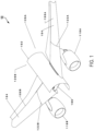
- an aircraft 100 that includes a fuselage and an aircraft wing with a continuous center section expanding beyond the fuselage is illustrated, in accordance with an illustrative example.
- the aircraft 100 is a low-wing aircraft.
- the aircraft 100 has a wing below the fuselage.
- the aircraft 100 includes an aircraft fuselage 102.
- the aircraft fuselage 102 can correspond to a main body section of the aircraft 100.
- the aircraft fuselage 102 can hold crew, passengers, cargo, etc.
- the aircraft 100 also includes an aircraft wing 104.
- the aircraft wing 104 is attached to the aircraft fuselage 102 in such a manner that the aircraft wing 104 is below the aircraft fuselage 102.
- the aircraft wing 104 includes a center wing section 106.
- the center wing section 106 has a continuous structure that spans beyond a first side 120A of the aircraft fuselage 102 and beyond a second side 120B of the aircraft fuselage 102.
- the aircraft wing 104 also includes a first outboard wing section 108A attached to a first end 122A of the center wing section 106, and a second outboard wing section 108B attached to a second end 122B of the center wing section 106.
- the first end 122A of the center wing section 106 is on the first side 120A of the aircraft fuselage 102
- the second end 122B of the center wing section 106 is on the second side 120B of the aircraft fuselage 102.
- first outboard wing section 108A can be attached to the first end 122A of the center wing section 106 by a first truss system (e.g., the first truss system 500A of Figure 7 ) that is accessible via a first closeout panel (e.g., the closeout panel 302A of Figure 3 ), and the second outboard wing section 108B can be attached to the second end 122B of the center wing section 106 by a second truss system (e.g., the second truss system 500B of Figure 7 ) that is accessible via a second closeout panel (e.g., the closeout panel 302B of Figure 4 ).
- a first truss system e.g., the first truss system 500A of Figure 7
- first closeout panel e.g., the closeout panel 302A of Figure 3
- second truss system e.g., the second truss system 500B of Figure 7
- the aircraft 100 also includes a first engine 110A mounted onto the center wing section 106 of the aircraft wing 104 and a second engine 110B mounted onto the center wing section 106 of the aircraft wing 104.
- first outboard wing section 108A is outboard the first engine 110A
- second outboard wing section 108B is outboard the second engine 110B.
- the center wing section 106 can have a large opening and closeout panel that enables aircraft personnel to have access to a very large portion of the center wing section 106 to perform maintenance operations on different aircraft systems. Additionally, by using a continuous center wing section 106 that extends beyond the aircraft fuselage 102, there are less interfaces (e.g., stringers) that need to carry the load through the outboard wing sections 108, which can lead to less fasteners. For example, because of the continuous nature of the center wing section 106, the center wing section 106 can carry a relatively large load with a reduced amount of fasteners compared to a smaller center wing section that does not extend beyond the aircraft fuselage 102.
- the center wing section 106 can carry a relatively large load with a reduced amount of fasteners compared to a smaller center wing section that does not extend beyond the aircraft fuselage 102.
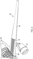
- FIG. 2 a portion of the aircraft wing 104 is illustrated, in accordance with an illustrative example.
- the portion of the aircraft wing 104 in Figure 2 can correspond to the portion of the aircraft wing 104 on the first side 120A of the aircraft fuselage 102 or the portion of the aircraft wing 104 on the second side 120B of the aircraft fuselage 102.
- the center wing section 106 of the aircraft wing 104 has a continuous structure that spans beyond the aircraft fuselage 102.
- the outboard wing section 108 is attached to the end 122 of the center wing section 106.
- the outboard wing section 108 can be attached to the end 122 of the center wing section 106 by a truss system 500 that is accessible via a closeout panel, such as the closeout panel 302A of Figure 3 or the closeout panel 302B of Figure 4 .
- the center wing section 106 can have a large opening and closeout panel that enables aircraft personnel to have access to a very large portion of the center wing section 106 to perform maintenance operations on different aircraft systems. Additionally, by using a continuous center wing section 106 that extends beyond the aircraft fuselage 102, there are less interfaces (e.g., stringers) that need to carry the load through the outboard wing sections 108, which can lead to less fasteners. For example, because of the continuous nature of the center wing section 106, the center wing section 106 can carry a relatively large load with a reduced amount of fasteners compared to a smaller center wing section that does not extend beyond the aircraft fuselage 102.
- the center wing section 106 can carry a relatively large load with a reduced amount of fasteners compared to a smaller center wing section that does not extend beyond the aircraft fuselage 102.
- FIG. 3 a bottom portion of the aircraft wing 104 on the first side 120A of the aircraft fuselage 102 is illustrated, in accordance with an illustrative example.
- Figure 3 the first end 122A of the center wing section 106 of the aircraft wing 104 is attached to the first outboard wing section 108A of the aircraft wing 104.
- Figure 3 also depicts a closeout panel 302A.
- the closeout panel 302A can provide access to a first truss system, such as a first occurrence of the truss system 500 of Figure 5 , which attaches the center wing section 106 of the aircraft wing 104 to the first outboard wing section 108A of the aircraft wing 104.
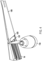
- FIG. 4 a bottom portion of the aircraft wing 104 on the second side 120B of the aircraft fuselage 102 is illustrated, in accordance with an illustrative example.
- Figure 4 the second end 122B of the center wing section 106 of the aircraft wing 104 is attached to the second outboard wing section 108B of the aircraft wing 104.
- Figure 3 also depicts a closeout panel 302B.
- the closeout panel 302B can provide access to a second truss system, such as a second occurrence of the truss system 500 of Figure 5 , which attaches the center wing section 106 of the aircraft wing 104 to the second outboard wing section 108B of the aircraft wing 104.
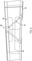
- a truss system 500 that attaches the center wing section 106 of the aircraft wing 104 to the outboard wing section 108 of the aircraft wing 104 is illustrated, in accordance with an illustrative example.
- the truss system 500 is an arrangement of struts configured in a triangular shape.
- the truss system 500 is a triangulated system of straight interconnected structural elements (e.g., members or struts) connected at nodes.
- the external forces applied to the truss system 500 and the reactions at the supports are generally applied at the nodes.
- the truss system 500 can be accessible by the closeout panel 302A when the outboard wing section 108 corresponds to the outboard wing section 108A on the first side 120A of the aircraft fuselage 102.
- truss system 500 can be accessible by an access panel opening 590 associated with the closeout panel 302A.
- the truss system 500 can be accessible by the closeout panel 302B when the outboard wing section 108 corresponds to the outboard wing section 108B on the second side 120B of the aircraft fuselage 102.
- truss system 500 can be accessible by an access panel opening 590 associated with the closeout panel 302B.
- the truss system 500 includes one or more stringers 502 (e.g., a plurality of stringers 502) that run along the aircraft wing 104.
- the stringers 502 or stiffeners can correspond to thin strips of materials or beams that run span-wise along the aircraft wing 104 and are attached to the ribs of the aircraft wing 104. Because the center wing section 106 is coupled to outboard wing section 108, the center wing section 106 and the outboard wing section 108 can include stringers 502 that are coupled together by the spars 504, 506, as described below.
- the truss system 500 also includes one or more front spars 504.
- the front spars 504 are coupled to the stringers 502 that run along a top portion of the aircraft wing 104 and along a bottom portion of the aircraft wing 104.
- the one or more front spars 504 of the truss system 500 are coupled to the stringers 502 that run along the center wing section 106 of the aircraft wing 104 and to the stringers 502 that run along the outboard wing section 108 of the aircraft wing 104.
- the front spars 504 can be comprised of members that are coupled together via fasteners.
- the members of the spars 504 can be comprises of metal, wood, or a composite material.
- the truss system 500 also includes one or more rear spars 506.
- the rear spars 506 are coupled to the stringers 502 that run along a top portion of the aircraft wing 104 and along a bottom portion of the aircraft wing 104.
- the one or more rear spars 506 of the truss system 500 are coupled to the stringers 502 that run along the center wing section 106 of the aircraft wing 104 and to the stringers 502 that run along the outboard wing section 108 of the aircraft wing 104.
- the rear spars 506 can be comprised of members that are coupled together via fasteners.
- the members of the spars 506 can be comprises of metal, wood, or a composite material.
- a load can be transferred along the one or more stringers 502, the one or more front spars 504, and the one or more rear spars 506 of the truss system 500.
- the truss system 600 can correspond to the truss system 500 of Figure 5 .
- the truss system 600 can be accessible by the closeout panel 302A when the outboard wing section 108 corresponds to the outboard wing section 108A on the first side 120A of the aircraft fuselage 102.
- the truss system 600 can be accessible by the closeout panel 302B when the outboard wing section 108 corresponds to the outboard wing section 108B on the second side 120B of the aircraft fuselage 102.
- the truss system 600 includes the one or more stringers 502 (e.g., a plurality of stringers 502) that run along the aircraft wing 104.
- the truss system 500 also includes one or more spars 610.
- the spars 610 in the truss system 600 can corresponds to the front spars 504 in the truss system 500 of Figure 5 , the rear spars 506 in the truss system 500 of Figure 5 , or both.
- the spars 610 are coupled to the stringers 502 that run along a top portion of the aircraft wing 104 and along a bottom portion of the aircraft wing 104.
- the one or more spars 610 of the truss system 600 are coupled to the stringers 502 that run along the center wing section 106 of the aircraft wing 104 and to the stringers 502 that run along the outboard wing section 108 of the aircraft wing 104.
- a load can be transferred along the one or more stringers 502 and the one or more spars 610 of the truss system 600.
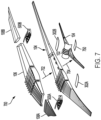
- a process 700 for constructing an aircraft wing and attaching the aircraft wing to a fuselage is illustrated, in accordance with an illustrative example.
- the aircraft wing 104 is constructed (e.g., assembled).
- the center wing section 106 of the aircraft wing 104 is attached to the outboard wing section 108A by a first truss system 500A.
- the first truss system 500A is accessible via the first closeout panel 302A.
- the center wing section 106 of the aircraft wing 104 is attached to the outboard wing section 108B by a second truss system 500B.
- the second truss system 500B is accessible via the second closeout panel 302B.
- a center wing closeout panel 750 can be used to access a center wing access panel opening 802, as described in greater detail with respect to Figure 8 .
- the center wing closeout panel 750 can have external fasteners aligned to truss members inside the center wing section 106 of the aircraft wing 104. As a result, the center wing closeout panel 750 can have a smooth fitting with the center wing section 106 with respect to external fasteners.
- FIG. 8 a bottom view of the center wing section 106 of the aircraft wing 104 is illustrated, in accordance with an illustrative example.
- the center wing section 106 of the aircraft wing 104 includes at least one center wing access panel opening 802.
- the center wing access panel opening 802 can be accessible via the center wing closeout panel 750.
- the center wing access panel opening 802 is between a first access panel opening associated with the first closeout panel 302A (e.g., an access panel opening to access the truss system 500A) and a second access panel opening associated with the second closeout panel 302B (e.g., an access panel opening to access the truss system 500B).
- the center wing access panel opening 802 can provide a relatively large area for personnel to access the internal structure and systems included within the continuous center wing section 106.
- at least one aircraft system can be accessible via the at least one center wing access panel opening 802.
- a fuel system can be accessible via the at least one center wing access panel opening 802.
- the layout of the center wing access panel opening 802 can improve the feasibility of maintenance operations for internal structure and systems.
- FIG. 9 a process 900 for attaching an aircraft wing to a fuselage is illustrated, in accordance with an illustrative example.
- a closed-shaped bracket 904 is coupled to the center wing section 106 of the aircraft wing 104.
- a plurality of fasteners can be used to couple the closed-shaped bracket 904 to a rib 910 of the center wing section 106 of the aircraft wing 104.
- a center portion of the closed-shaped bracket 904 can have the shape of an upside-down letter "V".
- the center portion of the closed-shaped bracket 904 can have an apex that is comprised from slanted members of the closed-shaped bracket 904 meeting.
- an open-shaped bracket 902 is coupled to a side of the aircraft fuselage 102 (not shown in Figure 9 ).
- a plurality of fasteners can be used to couple the open-shaped bracket 902 to the aircraft fuselage 102.
- a center portion of the open-shaped bracket 902 can have an opening that is shaped to fit the center portion of the closed-shaped bracket 904.
- the center portion of the open-shaped bracket 902 can have the shape of an upside-down letter "Y".
- the process 900 facilitates the attachment of the open-shaped bracket 902 to the closed-shaped bracket 904.
- the apex of the closed-shaped bracket 904 is inserted into the opening of the open-shaped bracket 902.
- a plurality of fasteners couple the open-shaped bracket 902 to the closed-shaped bracket 904.
- the fasteners can penetrate the opening of the open-shaped bracket 902, the members forming the apex of the closed-shaped bracket 904, and the aircraft fuselage 102, as depicted in Figures 10 and 11 .
- a smaller number of fasteners can be used to attach the aircraft wing 104 to the aircraft fuselage 102.
- inserting the apex of the closed-shaped bracket 904 into the opening of the open-shaped bracket 902 can provide added support that reduces the need to have a relatively large amount of fasteners to ensure that the aircraft wing 104 is adequately attached to the aircraft fuselage 102.
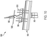
- FIG. 10 another process 1000 for attaching an aircraft wing to a fuselage is illustrated, in accordance with an illustrative example.
- the closed-shaped bracket 904 is coupled to the center wing section 106 of the aircraft wing 104.
- a plurality of fasteners 1010 can be used to couple the closed-shaped bracket 904 to the rib 910 of the center wing section 106 of the aircraft wing 104.
- the open-shaped bracket 902 is coupled to a side of the aircraft fuselage 102 (not shown in Figure 10 ).
- a plurality of fasteners (not shown in Figure 10 ) can be used to couple the open-shaped bracket 902 to the aircraft fuselage 102.
- the process 1000 facilitates the attachment of the open-shaped bracket 902 to the closed-shaped bracket 904.
- the apex of the closed-shaped bracket 904 is inserted into the opening of the open-shaped bracket 902.
- a plurality of fasteners 1020 couple the open-shaped bracket 902 to the closed-shaped bracket 904.
- the fasteners 1020 can penetrate the opening of the open-shaped bracket 902, the members forming the apex of the closed-shaped bracket 904, and the aircraft fuselage 102.
- a smaller number of fasteners 1020 can be used to attach the aircraft wing 104 to the aircraft fuselage 102.
- inserting the apex of the closed-shaped bracket 904 into the opening of the open-shaped bracket 902 can provide added support that reduces the need to have a relatively large amount of fasteners to ensure that the aircraft wing 104 is adequately attached to the aircraft fuselage 102.
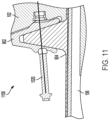
- FIG. 11 another process 1100 for attaching an aircraft wing to a fuselage is illustrated, in accordance with an illustrative example.
- the closed-shaped bracket 904 is coupled to the center wing section 106 of the aircraft wing 104, and the open-shaped bracket 902 is coupled to a side of the aircraft fuselage 102.
- the process 1100 facilitates the attachment of the open-shaped bracket 902 to the closed-shaped bracket 904.
- the apex of the closed-shaped bracket 904 is inserted into the opening of the open-shaped bracket 902.
- a plurality of fasteners 1020 couple the open-shaped bracket 902 to the closed-shaped bracket 904.
- the fasteners 1020 can penetrate the opening of the open-shaped bracket 902, the members forming the apex of the closed-shaped bracket 904, and the aircraft fuselage 102.
- a single fastener 1020 is depicted in Figure 11 , in other examples, multiple fasteners 1020 can be used to couple the brackets 902, 904 to the aircraft fuselage 102.
- twenty-eight (28) fasteners 1020 e.g., through bolts
- a smaller number of fasteners 1020 can be used to attach the aircraft wing 104 to the aircraft fuselage 102.
- inserting the apex of the closed-shaped bracket 904 into the opening of the open-shaped bracket 902 can provide added support that reduces the need to have a relatively large amount of fasteners to ensure that the aircraft wing 104 is adequately attached to the aircraft fuselage 102.
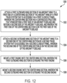
- Figure 12 illustrates a flow chart of a method 1200, according to an illustrative example.
- the method 1200 includes attaching a first outboard wing section of an aircraft wing to a first end of a center wing section of the aircraft wing by a first truss system that is accessible via a first closeout panel, at block 1202.
- the center wing section has a continuous structure that spans beyond a first side of an aircraft fuselage and beyond a second side of the aircraft fuselage, and the first end of the center wing section is on the first side of the aircraft fuselage.
- the first outboard wing section 108A of the aircraft wing 104 is attached to the first end 122A of the center wing section 106 of the aircraft wing 104 by the first truss system 500A that is accessible via the first closeout panel 302A.
- the center wing section 106 has a continuous structure that spans beyond the first side 120A of the aircraft fuselage 102 and beyond the second side 120B of the aircraft fuselage 102, and the first end 122A of the center wing section 106 is on the first side 120A of the aircraft fuselage 102.
- the method 1200 also includes attaching a second outboard wing section of the aircraft wing to a second end of the center wing section by a second truss system that is accessible via a second closeout panel, at block 1204.
- the second end of the center wing section is on the second side of the aircraft fuselage.
- the second outboard wing section 108B of the aircraft wing 104 is attached to the second end 122B of the center wing section 106 by the second truss system 500B that is accessible via the second closeout panel 302B.
- the second end 122B of the center wing section 106 is on the second side 120B of the aircraft fuselage 102.
- the method 1200 also includes mounting a first engine onto the center wing section, at block 1206.
- the first outboard wing section is outboard the first engine.
- the first engine 110A is mounted onto the center wing section 106.
- the first outboard wing section 108A is outboard the first engine 110A.
- the method 1200 also includes mounting a second engine onto the center wing section, at block 1208.
- the second outboard wing section is outboard the second engine.
- the second engine 110B is mounted onto the center wing section 106.
- the second outboard wing section 108B is outboard the second engine 110B.
- the first truss system 500A includes, at least, one or more stringers 502, one or more front spars 504, and one or more rear spars 506.
- a first load can be transferred along the one or more stringers 502, the one or more front spars 504, and the one or more rear spars 506.
- the first truss system 500A can be accessible through a first access panel opening (e.g., the access panel opening 590) associated with the first closeout panel 302A.
- the second truss system 500B includes, at least, one or more stringers 502, one or more front spars 504, and one or more rear spars 506.
- a second load can be transferred along the one or more stringers 502, the one or more front spars 504, and the one or more rear spars 506.
- the second truss system 500B can be accessible through a second access panel opening (e.g., the access panel opening 590) associated with the second closeout panel 302B.
- the method 1200 includes coupling a first open-shaped bracket to the first side of the aircraft fuselage and coupling a first closed-shaped bracket to the center wing section at a first location proximate to the first side of the aircraft fuselage.
- the open-shaped bracket 902 can be coupled to the first side 120A of the aircraft fuselage 102 and the closed-shaped bracket 904 can be coupled to the center wing section 106 at a first location proximate to the first side 120A of the aircraft fuselage 102.
- the method 1200 can also include coupling the first open-shaped bracket to the first closed-shaped bracket.
- the fasteners 1020 can couple the open-shaped bracket 902 to the closed-shaped bracket 904.
- the method 1200 includes coupling a second open-shaped bracket to the second side of the aircraft fuselage and coupling a second closed-shaped bracket to the center wing section at a second location proximate to the second side of the aircraft fuselage.
- the open-shaped bracket 902 can be coupled to the second side 120B of the aircraft fuselage 102 and the closed-shaped bracket 904 can be coupled to the center wing section 106 at a second location proximate to the second side 120B of the aircraft fuselage 102.
- the method 1200 can also include coupling the second open-shaped bracket to the second closed-shaped bracket.
- the fasteners 1020 can couple the open-shaped bracket 902 to the closed-shaped bracket 904.
- the center wing section 106 includes at least one center wing access panel opening 802 that is accessible via a center wing closeout panel 750.
- the at least one center wing access panel opening 802 is between a first access panel opening associated with the first closeout panel 302A and a second access panel opening associated with the second closeout panel 302B.
- at least one aircraft system is accessible via the at least one center wing access panel opening 802.
- a fuel system is accessible via the at least one center wing access panel opening 802.
- the aircraft wing 104 By constructing the aircraft wing 104 such that the outboard wing sections 108 are outboard the engines 110, internal structure and systems related to the engines 110 and fuel management can be included within the continuous center wing section 106 of the aircraft wing 104. Additionally, by using a continuous center wing section 106 that extends beyond the aircraft fuselage 102, there are less interfaces (e.g., stringers) that need to carry the load through the outboard wing sections 108, which can lead to less fasteners. For example, because of the continuous nature of the center wing section 106, the center wing section 106 can carry a relatively large load with a reduced amount of fasteners compared to a smaller center wing section that does not extend beyond the aircraft fuselage 102.
- the center wing section 106 can carry a relatively large load with a reduced amount of fasteners compared to a smaller center wing section that does not extend beyond the aircraft fuselage 102.
- system can be a vehicle other than an aircraft without departing from the essence of the present disclosure.
- instances in this specification where one element is "coupled" to another element can include direct and indirect coupling.
- Direct coupling can be defined as one element coupled to and in some contact with another element.
- Indirect coupling can be defined as coupling between two elements not in direct contact with each other, but having one or more additional elements between the coupled elements.
- securing one element to another element can include direct securing and indirect securing.
- adjacent does not necessarily denote contact. For example, one element can be adjacent another element without being in contact with that element.
- a system, apparatus, structure, article, element, component, or hardware “configured to” perform a specified function is indeed capable of performing the specified function without any alteration, rather than merely having potential to perform the specified function after further modification.
- the system, apparatus, structure, article, element, component, or hardware “configured to” perform a specified function is specifically selected, created, implemented, utilized, programmed, and/or designed for the purpose of performing the specified function.
- "configured to” denotes existing characteristics of a system, apparatus, structure, article, element, component, or hardware which enable the system, apparatus, structure, article, element, component, or hardware to perform the specified function without further modification.
- a system, apparatus, structure, article, element, component, or hardware described as being “configured to” perform a particular function may additionally or alternatively be described as being “adapted to” and/or as being “operative to” perform that function.
- first, second, etc. are used herein merely as labels, and are not intended to impose ordinal, positional, or hierarchical requirements on the items to which these terms refer. Moreover, reference to, e.g., a “second” item does not require or preclude the existence of, e.g., a "first” or lower-numbered item, and/or, e.g., a "third" or higher-numbered item.
Landscapes
- Engineering & Computer Science (AREA)
- Mechanical Engineering (AREA)
- Aviation & Aerospace Engineering (AREA)
- Connection Of Plates (AREA)
Abstract
Description
- The present disclosure generally relates to aircrafts, and more particularly, to a wing structure for an aircraft.
- This background description is provided for the purpose of generally presenting the context of the disclosure. Unless otherwise indicated herein, material described in this section is neither expressly nor impliedly admitted to be prior art to the present disclosure or the appended claims.
- Low-wing aircrafts typically include a structural joint (e.g., a wing joint) proximate to a side of a fuselage where a center section of an aircraft wing is connected to an aircraft wing box. The aircraft wing box typically is a load-carrying structure of the aircraft wing that serves as an attachment point for other wing components, such as leading edge flaps, trailing edge flaps, and wing-tip devices. Because the aircraft wing box is proximate to the fuselage, the center section of the aircraft wing may be relatively small. As a result, a lot of internal structure and systems related to the engine and fuel management is outboard of the center section of the aircraft wing, where space is relatively confined.
- The present application is directed to an improved aircraft wing structure. In particular, according to the techniques described herein, a center section of an aircraft wing has a continuous structure, and a wing joint of the aircraft wing is outboard an engine. By constructing the aircraft wing such that the wing joint is outboard the engine, internal structure and systems related to the engine and fuel management can be included in the center section of the aircraft wing. Additionally, by constructing the aircraft wing such that the wing joint is outboard the engine, there are less interfaces (e.g., stringers) that need to carry the load through an outboard wing section, which can lead to less fasteners. In some examples, the center section of the aircraft wing can have a large opening and closeout panel that enables aircraft personnel to have access to a very large portion of the center section.
- The aircraft wing can be attached to an aircraft fuselage using a self-aligning interface. Primary loads for the aircraft wing to the fuselage are vertical (e.g., in the "up" direction) with maneuvering loads and landing loads acting as primary drivers. The reverse maneuvering loads associated with the aircraft fuselage are less than the primary loads for the aircraft wing. As a result, the self-aligning interface can transfer the large load through features (e.g., structural design features) of the interface as opposed to solely relying on fasteners.
- In a first aspect, the present application discloses an aircraft structure. The aircraft structure includes an aircraft wing. The aircraft wing includes a center wing section having a continuous structure that spans beyond a first side of an aircraft fuselage and beyond a second side of the aircraft fuselage. The aircraft wing also includes a first outboard wing section attached to a first end of the center wing section by a first truss system that is accessible via a first closeout panel. The first end of the center wing section in on the first side of the aircraft fuselage. The aircraft wing also includes a second outboard wing section attached to a second end of the center wing section by a second truss system that is accessible via a second closeout panel. The second end of the center wing section is on the second side of the aircraft fuselage.
- The aircraft structure may include a first engine mounted onto the center wing section, wherein the first outboard wing section is outboard the first engine, and a second engine mounted onto the center wing section, wherein the second outboard wing section is outboard the second engine.
- The first truss system may comprise, at least, one or more stringers, one or more front spars, and one or more rear spars, wherein a first load may be transferred along the one or more stringers, the one or more front spars, and the one or more rear spars.
- The second truss system may comprise, at least, one or more stringers, one or more front spars, and one or more rear spars, wherein a second load may be transferred along the one or more stringers, the one or more front spars, and the one or more rear spars.
- The first truss system may be accessible through a first access panel opening associated with the first closeout panel, wherein the second truss system may be accessible through a second access panel opening associated with the second closeout panel.
- The aircraft structure may further include a first open-shaped bracket coupled to the first side of the aircraft fuselage, a first closed-shaped bracket coupled to the center wing section at a first location proximate to the first side of the aircraft fuselage, wherein a first apex of the first closed-shaped bracket is inserted into an opening of the first open-shaped bracket, and a first plurality of fasteners that couple the first open-shaped bracket to the first closed-shaped bracket. The aircraft structure can preferably further comprise a second open-shaped bracket coupled to the second side of the aircraft fuselage, a second closed-shaped bracket coupled to the center wing section at a second location proximate to the second side of the aircraft fuselage, wherein a second apex of the second closed-shaped bracket is inserted into an opening of the second open-shaped bracket, and a second plurality of fasteners that couple the second open-shaped bracket to the second closed-shaped bracket.
- The center wing section may comprise at least one center wing access panel opening that is accessible via a center wing closeout panel, and wherein the at least one center wing access panel opening is between a first access panel opening associated with the first closeout panel and a second access panel opening associated with the second closeout panel. Preferably, at least one aircraft system is accessible via the at least one center wing access panel opening. Further preferably, a fuel system is accessible via the at least one center wing access panel opening.
- In a second aspect, the present application discloses a method of fabricating an aircraft structure. The method includes attaching a first outboard wing section of an aircraft wing to a first end of a center wing section of the aircraft wing by a first truss system that is accessible via a first closeout panel. The center wing section has a continuous structure that spans beyond a first side of an aircraft fuselage and beyond a second side of the aircraft fuselage. The first end of the center wing section is on the first side of the aircraft fuselage. The method also includes attaching a second outboard wing section of the aircraft wing to a second end of the center wing section by a second truss system that is accessible via a second closeout panel. The second end of the center wing section is on the second side of the aircraft fuselage. The method also includes mounting a first engine onto the center wing section and mounting a second engine onto the center wing section. The first outboard wing section is outboard the first engine, and the second outboard wing section is outboard the second engine.
- The first truss system may comprise, at least, one or more stringers, one or more front spars, and one or more rear spars, wherein a first load may be transferred along the one or more stringers, the one or more front spars, and the one or more rear spars.
- The second truss system may comprise, at least, one or more stringers, one or more front spars, and one or more rear spars, wherein a second load may be transferred along the one or more stringers, the one or more front spars, and the one or more rear spars.
- The first truss system may be accessible through a first access panel opening associated with the first closeout panel, wherein the second truss system may be accessible through a second access panel opening associated with the second closeout panel.
- The method may further include coupling a first open-shaped bracket to the first side of the aircraft fuselage, coupling a first closed-shaped bracket to the center wing section at a first location proximate to the first side of the aircraft fuselage, wherein a first apex of the first closed-shaped bracket is inserted into an opening of the first open-shaped bracket, and coupling the first open-shaped bracket to the first closed-shaped bracket. Preferably, the method further includes coupling a second open-shaped bracket to the second side of the aircraft fuselage, coupling a second closed-shaped bracket to the center wing section at a second location proximate to the second side of the aircraft fuselage, wherein a second apex of the second closed-shaped bracket is inserted into an opening of the second open-shaped bracket, and coupling the second open-shaped bracket to the second closed-shaped bracket.
- In a third aspect, the present application discloses an aircraft. The aircraft includes a fuselage and an aircraft wing. The aircraft wing includes a center wing section having a continuous structure that spans beyond a first side of the fuselage and beyond a second side of the fuselage. The aircraft wing also includes a first outboard wing section attached to a first end of the center wing section by a first truss system that is accessible via a first closeout panel. The first end of the center wing section is on the first side of the aircraft fuselage. The aircraft wing also includes a second outboard wing section attached to a second end of the center wing section by a second truss system that is accessible via a second closeout panel. The second end of the center wing section is on the second side of the aircraft fuselage. The aircraft also includes a first engine mounted onto the center wing section and a second engine mounted onto the center wing section. The first outboard wing section is outboard the first engine, and the second outboard wing section is outboard the second engine.
- The aircraft may include a first open-shaped bracket coupled to the first side of the fuselage, a first closed-shaped bracket coupled to the center wing section at a first location proximate to the first side of the fuselage, wherein a first apex of the first closed-shaped bracket is inserted into an opening of the first open-shaped bracket, and a first plurality of fasteners that couple the first open-shaped bracket to the first closed-shaped bracket.
- The aircraft may include a second open-shaped bracket coupled to the second side of the fuselage, a second closed-shaped bracket coupled to the center wing section at a second location proximate to the second side of the fuselage, wherein a second apex of the second closed-shaped bracket is inserted into an opening of the second open-shaped bracket, and a second plurality of fasteners that couple the second open-shaped bracket to the second closed-shaped bracket.
- The center wing section may comprise at least one center wing access panel opening that is accessible via a center wing closeout panel, wherein the at least one center wing access panel opening may be between a first access panel opening associated with the first closeout panel and a second access panel opening associated with the second closeout panel.
- In a fourth aspect, the present application discloses an aircraft. The aircraft includes a fuselage and an aircraft structure according to the first aspect. The aircraft further includes a first engine mounted onto the center wing section and a second engine mounted onto the center wing section. The first outboard wing section is outboard the first engine, and the second outboard wing section is outboard the second engine.
- The foregoing summary is illustrative only and is not intended to be in any way limiting. In addition to the illustrative aspects, examples, and features described above, further aspects, examples, and features will become apparent by reference to the figures and the following detailed description.
- A more complete understanding of examples of the present application may be derived by referring to the detailed description and claims when considered in conjunction with the following figures, wherein like reference numbers may refer to similar elements throughout the figures. The figures are provided to facilitate understanding of the disclosure without limiting the breadth, scope, scale, or applicability of the disclosure. The drawings are not necessarily made to scale.
-
Figure 1 illustrates an aircraft that includes a fuselage and an aircraft wing with a continuous center section expanding beyond the fuselage, according to an illustrative example; -
Figure 2 illustrates a portion of an aircraft wing, according to an illustrative example; -
Figure 3 illustrates a bottom portion of an aircraft wing on a first side of a fuselage, according to an illustrative example; -
Figure 4 illustrates a bottom portion of an aircraft wing on a second side of a fuselage, according to an illustrative example; -
Figure 5 illustrates a truss system that attaches a center wing section of an aircraft wing to an outboard wing section of the aircraft wing, according to an illustrative example; -
Figure 6 illustrates another truss system that attaches a center wing section of an aircraft wing to an outboard wing section of the aircraft wing, according to an illustrative example; -
Figure 7 illustrates a process for constructing an aircraft wing and attaching the aircraft wing to a fuselage, in accordance with an illustrative example; -
Figure 8 illustrates a bottom view of a center wing section of an aircraft wing, in accordance with an illustrative example; -
Figure 9 illustrates a process for attaching an aircraft wing to a fuselage, in accordance with an illustrative example; -
Figure 10 illustrates another process for attaching an aircraft wing to a fuselage, in accordance with an illustrative example; -
Figure 11 illustrates another process for attaching an aircraft wing to a fuselage, in accordance with an illustrative example; and -
Figure 12 is a flowchart of an example of an implementation of a method, according to an illustrative example. - The figures and the following description illustrate specific illustrative examples. It will be appreciated that those skilled in the art will be able to devise various arrangements that, although not explicitly described or shown herein, embody the principles described herein and are included within the scope of the claims that follow this description. Furthermore, any examples described herein are intended to aid in understanding the principles of the disclosure and are to be construed as being without limitation. As a result, this disclosure is not limited to the specific embodiments or examples described below, but by the claims.
- Particular implementations are described herein with reference to the drawings. In the description, common features may be designated by common reference numbers throughout the drawings. In some drawings, multiple instances of a particular type of feature are used. Although these features are physically and/or logically distinct, the same reference number is used for each, and the different instances are distinguished by addition of a letter to the reference number. When the features as a group or a type are referred to herein (e.g., when no particular one of the features is being referenced), the reference number is used without a distinguishing letter. However, when one particular feature of multiple features of the same type is referred to herein, the reference number is used with the distinguishing letter. For example, referring to
Figure 1 , engines are illustrated and associated withreference number 110. When referring to a particular one of the engines, such as theengine 110A, the distinguishing letter "A" is used. However, when referring to any arbitrary one of the engines or to the engines as a group, thereference number 110 may be used without a distinguishing letter. - As used herein, various terminology is used for the purpose of describing particular implementations only and is not intended to be limiting. For example, the singular forms "a," "an," and "the" are intended to include the plural forms as well, unless the context clearly indicates otherwise. Further, the terms "comprise," "comprises," and "comprising" are used interchangeably with "include," "includes," or "including." Additionally, the term "wherein" is used interchangeably with the term "where." As used herein, "exemplary" indicates an example, an implementation, and/or an aspect, and should not be construed as limiting or as indicating a preference or a preferred implementation. As used herein, an ordinal term (e.g., "first," "second," "third," etc.) used to modify an element, such as a structure, a component, an operation, etc., does not by itself indicate any priority or order of the element with respect to another element, but rather merely distinguishes the element from another element having a same name (but for use of the ordinal term). As used herein, the term "set" refers to a grouping of one or more elements, and the term "plurality" refers to multiple elements.
- Referring to
Figure 1 , anaircraft 100 that includes a fuselage and an aircraft wing with a continuous center section expanding beyond the fuselage is illustrated, in accordance with an illustrative example. In the example ofFigure 1 , theaircraft 100 is a low-wing aircraft. For example, theaircraft 100 has a wing below the fuselage. - To illustrate, the
aircraft 100 includes anaircraft fuselage 102. Theaircraft fuselage 102 can correspond to a main body section of theaircraft 100. Theaircraft fuselage 102 can hold crew, passengers, cargo, etc. Theaircraft 100 also includes anaircraft wing 104. As depicted inFigure 1 , theaircraft wing 104 is attached to theaircraft fuselage 102 in such a manner that theaircraft wing 104 is below theaircraft fuselage 102. - The
aircraft wing 104 includes acenter wing section 106. Thecenter wing section 106 has a continuous structure that spans beyond afirst side 120A of theaircraft fuselage 102 and beyond a second side 120B of theaircraft fuselage 102. Theaircraft wing 104 also includes a firstoutboard wing section 108A attached to afirst end 122A of thecenter wing section 106, and a secondoutboard wing section 108B attached to asecond end 122B of thecenter wing section 106. Thefirst end 122A of thecenter wing section 106 is on thefirst side 120A of theaircraft fuselage 102, and thesecond end 122B of thecenter wing section 106 is on the second side 120B of theaircraft fuselage 102. As described below, the firstoutboard wing section 108A can be attached to thefirst end 122A of thecenter wing section 106 by a first truss system (e.g., thefirst truss system 500A ofFigure 7 ) that is accessible via a first closeout panel (e.g., thecloseout panel 302A ofFigure 3 ), and the secondoutboard wing section 108B can be attached to thesecond end 122B of thecenter wing section 106 by a second truss system (e.g., thesecond truss system 500B ofFigure 7 ) that is accessible via a second closeout panel (e.g., thecloseout panel 302B ofFigure 4 ). - The
aircraft 100 also includes afirst engine 110A mounted onto thecenter wing section 106 of theaircraft wing 104 and asecond engine 110B mounted onto thecenter wing section 106 of theaircraft wing 104. Thus, the firstoutboard wing section 108A is outboard thefirst engine 110A, and the secondoutboard wing section 108B is outboard thesecond engine 110B. - By constructing the
aircraft wing 104 such that theoutboard wing sections 108 are outboard theengines 110, internal structure and systems related to theengines 110 and fuel management can be included within the continuouscenter wing section 106 of theaircraft wing 104. As described below, thecenter wing section 106 can have a large opening and closeout panel that enables aircraft personnel to have access to a very large portion of thecenter wing section 106 to perform maintenance operations on different aircraft systems. Additionally, by using a continuouscenter wing section 106 that extends beyond theaircraft fuselage 102, there are less interfaces (e.g., stringers) that need to carry the load through theoutboard wing sections 108, which can lead to less fasteners. For example, because of the continuous nature of thecenter wing section 106, thecenter wing section 106 can carry a relatively large load with a reduced amount of fasteners compared to a smaller center wing section that does not extend beyond theaircraft fuselage 102. - Referring to
Figure 2 , a portion of theaircraft wing 104 is illustrated, in accordance with an illustrative example. The portion of theaircraft wing 104 inFigure 2 can correspond to the portion of theaircraft wing 104 on thefirst side 120A of theaircraft fuselage 102 or the portion of theaircraft wing 104 on the second side 120B of theaircraft fuselage 102. - In
Figure 2 , thecenter wing section 106 of theaircraft wing 104 has a continuous structure that spans beyond theaircraft fuselage 102. Theoutboard wing section 108 is attached to theend 122 of thecenter wing section 106. As described below with respect toFigure 5 , theoutboard wing section 108 can be attached to theend 122 of thecenter wing section 106 by atruss system 500 that is accessible via a closeout panel, such as thecloseout panel 302A ofFigure 3 or thecloseout panel 302B ofFigure 4 . - By constructing the
aircraft wing 104 such that theoutboard wing sections 108 are outboard theengines 110, internal structure and systems related to theengines 110 and fuel management can be included within the continuouscenter wing section 106 of theaircraft wing 104. As described below, thecenter wing section 106 can have a large opening and closeout panel that enables aircraft personnel to have access to a very large portion of thecenter wing section 106 to perform maintenance operations on different aircraft systems. Additionally, by using a continuouscenter wing section 106 that extends beyond theaircraft fuselage 102, there are less interfaces (e.g., stringers) that need to carry the load through theoutboard wing sections 108, which can lead to less fasteners. For example, because of the continuous nature of thecenter wing section 106, thecenter wing section 106 can carry a relatively large load with a reduced amount of fasteners compared to a smaller center wing section that does not extend beyond theaircraft fuselage 102. - Referring to
Figure 3 , a bottom portion of theaircraft wing 104 on thefirst side 120A of theaircraft fuselage 102 is illustrated, in accordance with an illustrative example. - In
Figure 3 , thefirst end 122A of thecenter wing section 106 of theaircraft wing 104 is attached to the firstoutboard wing section 108A of theaircraft wing 104.Figure 3 also depicts acloseout panel 302A. Thecloseout panel 302A can provide access to a first truss system, such as a first occurrence of thetruss system 500 ofFigure 5 , which attaches thecenter wing section 106 of theaircraft wing 104 to the firstoutboard wing section 108A of theaircraft wing 104. - Referring to
Figure 4 , a bottom portion of theaircraft wing 104 on the second side 120B of theaircraft fuselage 102 is illustrated, in accordance with an illustrative example. - In
Figure 4 , thesecond end 122B of thecenter wing section 106 of theaircraft wing 104 is attached to the secondoutboard wing section 108B of theaircraft wing 104.Figure 3 also depicts acloseout panel 302B. Thecloseout panel 302B can provide access to a second truss system, such as a second occurrence of thetruss system 500 ofFigure 5 , which attaches thecenter wing section 106 of theaircraft wing 104 to the secondoutboard wing section 108B of theaircraft wing 104. - Referring to
Figure 5 , atruss system 500 that attaches thecenter wing section 106 of theaircraft wing 104 to theoutboard wing section 108 of theaircraft wing 104 is illustrated, in accordance with an illustrative example. Thetruss system 500 is an arrangement of struts configured in a triangular shape. In particular, thetruss system 500 is a triangulated system of straight interconnected structural elements (e.g., members or struts) connected at nodes. The external forces applied to thetruss system 500 and the reactions at the supports are generally applied at the nodes. Thetruss system 500 can be accessible by thecloseout panel 302A when theoutboard wing section 108 corresponds to theoutboard wing section 108A on thefirst side 120A of theaircraft fuselage 102. For example,truss system 500 can be accessible by an access panel opening 590 associated with thecloseout panel 302A. Alternatively, thetruss system 500 can be accessible by thecloseout panel 302B when theoutboard wing section 108 corresponds to theoutboard wing section 108B on the second side 120B of theaircraft fuselage 102. For example,truss system 500 can be accessible by an access panel opening 590 associated with thecloseout panel 302B. - The
truss system 500 includes one or more stringers 502 (e.g., a plurality of stringers 502) that run along theaircraft wing 104. Thestringers 502 or stiffeners can correspond to thin strips of materials or beams that run span-wise along theaircraft wing 104 and are attached to the ribs of theaircraft wing 104. Because thecenter wing section 106 is coupled tooutboard wing section 108, thecenter wing section 106 and theoutboard wing section 108 can includestringers 502 that are coupled together by thespars - The
truss system 500 also includes one or more front spars 504. The front spars 504 are coupled to thestringers 502 that run along a top portion of theaircraft wing 104 and along a bottom portion of theaircraft wing 104. To couplecenter wing section 106 to theoutboard wing section 108, the one or more front spars 504 of thetruss system 500 are coupled to thestringers 502 that run along thecenter wing section 106 of theaircraft wing 104 and to thestringers 502 that run along theoutboard wing section 108 of theaircraft wing 104. As illustrated inFigure 5 , the front spars 504 can be comprised of members that are coupled together via fasteners. The members of thespars 504 can be comprises of metal, wood, or a composite material. - The
truss system 500 also includes one or more rear spars 506. The rear spars 506 are coupled to thestringers 502 that run along a top portion of theaircraft wing 104 and along a bottom portion of theaircraft wing 104. To couplecenter wing section 106 to theoutboard wing section 108, the one or morerear spars 506 of thetruss system 500 are coupled to thestringers 502 that run along thecenter wing section 106 of theaircraft wing 104 and to thestringers 502 that run along theoutboard wing section 108 of theaircraft wing 104. As illustrated inFigure 5 , the rear spars 506 can be comprised of members that are coupled together via fasteners. The members of thespars 506 can be comprises of metal, wood, or a composite material. - A load can be transferred along the one or
more stringers 502, the one or more front spars 504, and the one or morerear spars 506 of thetruss system 500. - Referring to
Figure 6 , anothertruss system 600 that attaches thecenter wing section 106 of theaircraft wing 104 to theoutboard wing section 108 of theaircraft wing 104 is illustrated, in accordance with an illustrative example. In one example, thetruss system 600 can correspond to thetruss system 500 ofFigure 5 . Thetruss system 600 can be accessible by thecloseout panel 302A when theoutboard wing section 108 corresponds to theoutboard wing section 108A on thefirst side 120A of theaircraft fuselage 102. Alternatively, thetruss system 600 can be accessible by thecloseout panel 302B when theoutboard wing section 108 corresponds to theoutboard wing section 108B on the second side 120B of theaircraft fuselage 102. - The
truss system 600 includes the one or more stringers 502 (e.g., a plurality of stringers 502) that run along theaircraft wing 104. Thetruss system 500 also includes one or more spars 610. Thespars 610 in thetruss system 600 can corresponds to the front spars 504 in thetruss system 500 ofFigure 5 , the rear spars 506 in thetruss system 500 ofFigure 5 , or both. Thespars 610 are coupled to thestringers 502 that run along a top portion of theaircraft wing 104 and along a bottom portion of theaircraft wing 104. To couplecenter wing section 106 to theoutboard wing section 108, the one ormore spars 610 of thetruss system 600 are coupled to thestringers 502 that run along thecenter wing section 106 of theaircraft wing 104 and to thestringers 502 that run along theoutboard wing section 108 of theaircraft wing 104. - A load can be transferred along the one or
more stringers 502 and the one ormore spars 610 of thetruss system 600. - Referring to
Figure 7 , aprocess 700 for constructing an aircraft wing and attaching the aircraft wing to a fuselage is illustrated, in accordance with an illustrative example. - According to a
first stage 702 of theprocess 700, theaircraft wing 104 is constructed (e.g., assembled). For example, during thefirst stage 702, thecenter wing section 106 of theaircraft wing 104 is attached to theoutboard wing section 108A by afirst truss system 500A. Thefirst truss system 500A is accessible via thefirst closeout panel 302A. Additionally, during thefirst stage 702, thecenter wing section 106 of theaircraft wing 104 is attached to theoutboard wing section 108B by asecond truss system 500B. Thesecond truss system 500B is accessible via thesecond closeout panel 302B. - According to a
second stage 704 of theprocess 700, theaircraft wing 104 is attached to theaircraft fuselage 102. Thesecond stage 704 is described below in greater detail with respect to Figures 9-13. As illustrated inFigure 7 , a centerwing closeout panel 750 can be used to access a center wingaccess panel opening 802, as described in greater detail with respect toFigure 8 . The centerwing closeout panel 750 can have external fasteners aligned to truss members inside thecenter wing section 106 of theaircraft wing 104. As a result, the centerwing closeout panel 750 can have a smooth fitting with thecenter wing section 106 with respect to external fasteners. - Referring to
Figure 8 , a bottom view of thecenter wing section 106 of theaircraft wing 104 is illustrated, in accordance with an illustrative example. - The
center wing section 106 of theaircraft wing 104 includes at least one center wingaccess panel opening 802. The center wingaccess panel opening 802 can be accessible via the centerwing closeout panel 750. With respect to the layout and configuration of theaircraft wing 104, the center wingaccess panel opening 802 is between a first access panel opening associated with thefirst closeout panel 302A (e.g., an access panel opening to access thetruss system 500A) and a second access panel opening associated with thesecond closeout panel 302B (e.g., an access panel opening to access thetruss system 500B). - As described above, internal structure and systems related to the
engines 110 and fuel management can be included within the continuouscenter wing section 106 of theaircraft wing 104. The center wingaccess panel opening 802 can provide a relatively large area for personnel to access the internal structure and systems included within the continuouscenter wing section 106. In particular, at least one aircraft system can be accessible via the at least one center wingaccess panel opening 802. As a non-limiting example, a fuel system can be accessible via the at least one center wingaccess panel opening 802. Thus, the layout of the center wingaccess panel opening 802 can improve the feasibility of maintenance operations for internal structure and systems. - Referring to
Figure 9 , aprocess 900 for attaching an aircraft wing to a fuselage is illustrated, in accordance with an illustrative example. - According to the
process 900, a closed-shapedbracket 904 is coupled to thecenter wing section 106 of theaircraft wing 104. For example, a plurality of fasteners can be used to couple the closed-shapedbracket 904 to arib 910 of thecenter wing section 106 of theaircraft wing 104. As illustrated inFigure 9 , a center portion of the closed-shapedbracket 904 can have the shape of an upside-down letter "V". For example, the center portion of the closed-shapedbracket 904 can have an apex that is comprised from slanted members of the closed-shapedbracket 904 meeting. - According to the
process 900, an open-shapedbracket 902 is coupled to a side of the aircraft fuselage 102 (not shown inFigure 9 ). For example, a plurality of fasteners can be used to couple the open-shapedbracket 902 to theaircraft fuselage 102. As illustrated inFigure 9 , a center portion of the open-shapedbracket 902 can have an opening that is shaped to fit the center portion of the closed-shapedbracket 904. For example, the center portion of the open-shapedbracket 902 can have the shape of an upside-down letter "Y". - To attach the aircraft wing 104 (e.g., the
center wing section 106 of the aircraft wing 104) to theaircraft fuselage 102, theprocess 900 facilitates the attachment of the open-shapedbracket 902 to the closed-shapedbracket 904. For example, the apex of the closed-shapedbracket 904 is inserted into the opening of the open-shapedbracket 902. Afterwards, a plurality of fasteners couple the open-shapedbracket 902 to the closed-shapedbracket 904. For example, the fasteners can penetrate the opening of the open-shapedbracket 902, the members forming the apex of the closed-shapedbracket 904, and theaircraft fuselage 102, as depicted inFigures 10 and11 . - By inserting the apex of the closed-shaped
bracket 904 into the opening of the open-shapedbracket 902, a smaller number of fasteners can be used to attach theaircraft wing 104 to theaircraft fuselage 102. For example, inserting the apex of the closed-shapedbracket 904 into the opening of the open-shapedbracket 902 can provide added support that reduces the need to have a relatively large amount of fasteners to ensure that theaircraft wing 104 is adequately attached to theaircraft fuselage 102. - Referring to
Figure 10 , anotherprocess 1000 for attaching an aircraft wing to a fuselage is illustrated, in accordance with an illustrative example. - According to the
process 1000, the closed-shapedbracket 904 is coupled to thecenter wing section 106 of theaircraft wing 104. For example, a plurality offasteners 1010 can be used to couple the closed-shapedbracket 904 to therib 910 of thecenter wing section 106 of theaircraft wing 104. According to theprocess 1000, the open-shapedbracket 902 is coupled to a side of the aircraft fuselage 102 (not shown inFigure 10 ). For example, a plurality of fasteners (not shown inFigure 10 ) can be used to couple the open-shapedbracket 902 to theaircraft fuselage 102. - To attach the aircraft wing 104 (e.g., the
center wing section 106 of the aircraft wing 104) to theaircraft fuselage 102, theprocess 1000 facilitates the attachment of the open-shapedbracket 902 to the closed-shapedbracket 904. For example, the apex of the closed-shapedbracket 904 is inserted into the opening of the open-shapedbracket 902. Afterwards, a plurality offasteners 1020 couple the open-shapedbracket 902 to the closed-shapedbracket 904. For example, thefasteners 1020 can penetrate the opening of the open-shapedbracket 902, the members forming the apex of the closed-shapedbracket 904, and theaircraft fuselage 102. - By inserting the apex of the closed-shaped
bracket 904 into the opening of the open-shapedbracket 902, a smaller number offasteners 1020 can be used to attach theaircraft wing 104 to theaircraft fuselage 102. For example, inserting the apex of the closed-shapedbracket 904 into the opening of the open-shapedbracket 902 can provide added support that reduces the need to have a relatively large amount of fasteners to ensure that theaircraft wing 104 is adequately attached to theaircraft fuselage 102. - Referring to
Figure 11 , anotherprocess 1100 for attaching an aircraft wing to a fuselage is illustrated, in accordance with an illustrative example. - According to the
process 1100, the closed-shapedbracket 904 is coupled to thecenter wing section 106 of theaircraft wing 104, and the open-shapedbracket 902 is coupled to a side of theaircraft fuselage 102. To attach the aircraft wing 104 (e.g., thecenter wing section 106 of the aircraft wing 104) to theaircraft fuselage 102, theprocess 1100 facilitates the attachment of the open-shapedbracket 902 to the closed-shapedbracket 904. For example, the apex of the closed-shapedbracket 904 is inserted into the opening of the open-shapedbracket 902. Afterwards, a plurality offasteners 1020 couple the open-shapedbracket 902 to the closed-shapedbracket 904. For example, thefasteners 1020 can penetrate the opening of the open-shapedbracket 902, the members forming the apex of the closed-shapedbracket 904, and theaircraft fuselage 102. Although asingle fastener 1020 is depicted inFigure 11 , in other examples,multiple fasteners 1020 can be used to couple thebrackets aircraft fuselage 102. As a non-limiting example, in one example, twenty-eight (28) fasteners 1020 (e.g., through bolts) can be used to couple thebrackets aircraft fuselage 102. - By inserting the apex of the closed-shaped
bracket 904 into the opening of the open-shapedbracket 902, a smaller number offasteners 1020 can be used to attach theaircraft wing 104 to theaircraft fuselage 102. For example, inserting the apex of the closed-shapedbracket 904 into the opening of the open-shapedbracket 902 can provide added support that reduces the need to have a relatively large amount of fasteners to ensure that theaircraft wing 104 is adequately attached to theaircraft fuselage 102. -
Figure 12 illustrates a flow chart of amethod 1200, according to an illustrative example. - The
method 1200 includes attaching a first outboard wing section of an aircraft wing to a first end of a center wing section of the aircraft wing by a first truss system that is accessible via a first closeout panel, atblock 1202. The center wing section has a continuous structure that spans beyond a first side of an aircraft fuselage and beyond a second side of the aircraft fuselage, and the first end of the center wing section is on the first side of the aircraft fuselage. For example, referring toFigures 1 and7 , the firstoutboard wing section 108A of theaircraft wing 104 is attached to thefirst end 122A of thecenter wing section 106 of theaircraft wing 104 by thefirst truss system 500A that is accessible via thefirst closeout panel 302A. Thecenter wing section 106 has a continuous structure that spans beyond thefirst side 120A of theaircraft fuselage 102 and beyond the second side 120B of theaircraft fuselage 102, and thefirst end 122A of thecenter wing section 106 is on thefirst side 120A of theaircraft fuselage 102. - The
method 1200 also includes attaching a second outboard wing section of the aircraft wing to a second end of the center wing section by a second truss system that is accessible via a second closeout panel, atblock 1204. The second end of the center wing section is on the second side of the aircraft fuselage. For example, referring toFigures 1 and7 , the secondoutboard wing section 108B of theaircraft wing 104 is attached to thesecond end 122B of thecenter wing section 106 by thesecond truss system 500B that is accessible via thesecond closeout panel 302B. Thesecond end 122B of thecenter wing section 106 is on the second side 120B of theaircraft fuselage 102. - The
method 1200 also includes mounting a first engine onto the center wing section, atblock 1206. The first outboard wing section is outboard the first engine. For example, referring toFigure 1 , thefirst engine 110A is mounted onto thecenter wing section 106. The firstoutboard wing section 108A is outboard thefirst engine 110A. - The
method 1200 also includes mounting a second engine onto the center wing section, atblock 1208. The second outboard wing section is outboard the second engine. For example, referring toFigure 1 , thesecond engine 110B is mounted onto thecenter wing section 106. The secondoutboard wing section 108B is outboard thesecond engine 110B. - According to one implementation of the
method 1200, thefirst truss system 500A includes, at least, one ormore stringers 502, one or more front spars 504, and one or more rear spars 506. A first load can be transferred along the one ormore stringers 502, the one or more front spars 504, and the one or more rear spars 506. Thefirst truss system 500A can be accessible through a first access panel opening (e.g., the access panel opening 590) associated with thefirst closeout panel 302A. - According to one implementation of the
method 1200, thesecond truss system 500B includes, at least, one ormore stringers 502, one or more front spars 504, and one or more rear spars 506. A second load can be transferred along the one ormore stringers 502, the one or more front spars 504, and the one or more rear spars 506. Thesecond truss system 500B can be accessible through a second access panel opening (e.g., the access panel opening 590) associated with thesecond closeout panel 302B. - According to one implementation, the
method 1200 includes coupling a first open-shaped bracket to the first side of the aircraft fuselage and coupling a first closed-shaped bracket to the center wing section at a first location proximate to the first side of the aircraft fuselage. For example, the open-shapedbracket 902 can be coupled to thefirst side 120A of theaircraft fuselage 102 and the closed-shapedbracket 904 can be coupled to thecenter wing section 106 at a first location proximate to thefirst side 120A of theaircraft fuselage 102. Themethod 1200 can also include coupling the first open-shaped bracket to the first closed-shaped bracket. For example, thefasteners 1020 can couple the open-shapedbracket 902 to the closed-shapedbracket 904. - According to one implementation, the
method 1200 includes coupling a second open-shaped bracket to the second side of the aircraft fuselage and coupling a second closed-shaped bracket to the center wing section at a second location proximate to the second side of the aircraft fuselage. For example, the open-shapedbracket 902 can be coupled to the second side 120B of theaircraft fuselage 102 and the closed-shapedbracket 904 can be coupled to thecenter wing section 106 at a second location proximate to the second side 120B of theaircraft fuselage 102. Themethod 1200 can also include coupling the second open-shaped bracket to the second closed-shaped bracket. For example, thefasteners 1020 can couple the open-shapedbracket 902 to the closed-shapedbracket 904. - According to one implementation of the
method 1200, thecenter wing section 106 includes at least one center wing access panel opening 802 that is accessible via a centerwing closeout panel 750. The at least one center wingaccess panel opening 802 is between a first access panel opening associated with thefirst closeout panel 302A and a second access panel opening associated with thesecond closeout panel 302B. According to one implementation of themethod 1200, at least one aircraft system is accessible via the at least one center wingaccess panel opening 802. According to one implementation of themethod 1200, a fuel system is accessible via the at least one center wingaccess panel opening 802. - By constructing the
aircraft wing 104 such that theoutboard wing sections 108 are outboard theengines 110, internal structure and systems related to theengines 110 and fuel management can be included within the continuouscenter wing section 106 of theaircraft wing 104. Additionally, by using a continuouscenter wing section 106 that extends beyond theaircraft fuselage 102, there are less interfaces (e.g., stringers) that need to carry the load through theoutboard wing sections 108, which can lead to less fasteners. For example, because of the continuous nature of thecenter wing section 106, thecenter wing section 106 can carry a relatively large load with a reduced amount of fasteners compared to a smaller center wing section that does not extend beyond theaircraft fuselage 102. - Although the systems are described herein with specific reference to aircraft systems or aerospace vehicles, in other examples, the system can be a vehicle other than an aircraft without departing from the essence of the present disclosure.
- Additionally, instances in this specification where one element is "coupled" to another element can include direct and indirect coupling. Direct coupling can be defined as one element coupled to and in some contact with another element. Indirect coupling can be defined as coupling between two elements not in direct contact with each other, but having one or more additional elements between the coupled elements. Further, as used herein, securing one element to another element can include direct securing and indirect securing. Additionally, as used herein, "adjacent" does not necessarily denote contact. For example, one element can be adjacent another element without being in contact with that element.
- As used herein, a system, apparatus, structure, article, element, component, or hardware "configured to" perform a specified function is indeed capable of performing the specified function without any alteration, rather than merely having potential to perform the specified function after further modification. In other words, the system, apparatus, structure, article, element, component, or hardware "configured to" perform a specified function is specifically selected, created, implemented, utilized, programmed, and/or designed for the purpose of performing the specified function. As used herein, "configured to" denotes existing characteristics of a system, apparatus, structure, article, element, component, or hardware which enable the system, apparatus, structure, article, element, component, or hardware to perform the specified function without further modification. For purposes of this disclosure, a system, apparatus, structure, article, element, component, or hardware described as being "configured to" perform a particular function may additionally or alternatively be described as being "adapted to" and/or as being "operative to" perform that function.
- The flow chart diagrams included herein are generally set forth as logical flow chart diagrams. As such, the depicted order and labeled steps are indicative of one example of the presented method. Other steps and methods may be conceived that are equivalent in function, logic, or effect to one or more steps, or portions thereof, of the illustrated method. Additionally, the format and symbols employed are provided to explain the logical steps of the method and are understood not to limit the scope of the method. Although various arrow types and line types may be employed in the flow chart diagrams, they are understood not to limit the scope of the corresponding method. Indeed, some arrows or other connectors may be used to indicate only the logical flow of the method. For instance, an arrow may indicate a waiting or monitoring period of unspecified duration between enumerated steps of the depicted method. Additionally, the order in which a particular method occurs may or may not strictly adhere to the order of the corresponding steps shown.
- Unless otherwise indicated, the terms "first," "second," etc. are used herein merely as labels, and are not intended to impose ordinal, positional, or hierarchical requirements on the items to which these terms refer. Moreover, reference to, e.g., a "second" item does not require or preclude the existence of, e.g., a "first" or lower-numbered item, and/or, e.g., a "third" or higher-numbered item.
- While the systems and methods of operation have been described with reference to certain examples, it will be understood by those skilled in the art that various changes can be made and equivalents can be substituted without departing from the scope of the claims. Therefore, it is intended that the present methods and systems not be limited to the particular examples disclosed, but that the disclosed methods and systems include all examples falling within the scope of the appended claims.
Claims (15)
- An aircraft structure comprising:
an aircraft wing (104) comprising:a center wing section (106) having a continuous structure that spans beyond a first side (120A) of an aircraft fuselage (102) and beyond a second side (120B) of the aircraft fuselage (102);a first outboard wing section (108A) attached to a first end (122A) of the center wing section (108) by a first truss system (500A) that is accessible via a first closeout panel (302A), wherein the first end (122A) of the center wing section (108) is on the first side (120A) of the aircraft fuselage (102); anda second outboard wing section (108B) attached to a second end (122B) of the center wing section (108) by a second truss system (500B) that is accessible via a second closeout panel (302B), wherein the second end (122B) of the center wing section (108) is on the second side (120B) of the aircraft fuselage (102). - The aircraft structure of claim 1, further comprising:a first engine (110A) mounted onto the center wing section (106), wherein the first outboard wing section (108A) is outboard the first engine (110A); anda second engine (110B) mounted onto the center wing section (106), wherein the second outboard wing section (108B) is outboard the second engine (110B).
- The aircraft structure of claim 1 or 2, wherein the first truss system (500A) comprises, at least, one or more stringers (502), one or more front spars (504), and one or more rear spars (506), and wherein a first load is transferred along the one or more stringers (502), the one or more front spars (504), and the one or more rear spars (506).
- The aircraft structure of any one of claims 1-3, wherein the second truss system (500B) comprises, at least, one or more stringers (502), one or more front spars (504), and one or more rear spars (506), and wherein a second load is transferred along the one or more stringers (502), the one or more front spars (504), and the one or more rear spars (506).
- The aircraft structure of any one of claims 1-4, wherein the first truss system (500A) is accessible through a first access panel opening (590) associated with the first closeout panel (302A), and wherein the second truss system (500B) is accessible through a second access panel opening (590) associated with the second closeout panel (302B).
- The aircraft structure of any one of claims 1-5, further comprising:a first open-shaped bracket (902) coupled to the first side (120A) of the aircraft fuselage (102);a first closed-shaped bracket (904) coupled to the center wing section (106) at a first location proximate to the first side (120A) of the aircraft fuselage (102), wherein a first apex of the first closed-shaped bracket (904) is inserted into an opening of the first open-shaped bracket (902); anda first plurality of fasteners (1020) that couple the first open-shaped bracket (902) to the first closed-shaped bracket (904).
- The aircraft structure of claim 6, further comprising:a second open-shaped bracket (902) coupled to the second side (120B) of the aircraft fuselage (102);a second closed-shaped bracket (904) coupled to the center wing section (106) at a second location proximate to the second side (120B) of the aircraft fuselage (102), wherein a second apex of the second closed-shaped bracket (904) is inserted into an opening of the second open-shaped bracket (902); anda second plurality of fasteners (1020) that couple the second open-shaped bracket (902) to the second closed-shaped bracket (904).
- The aircraft structure of any one of claims 1-7, wherein the center wing section (106) comprises at least one center wing access panel opening (802) that is accessible via a center wing closeout panel (750), and wherein the at least one center wing access panel opening (802) is between a first access panel opening associated with the first closeout panel (302A) and a second access panel opening associated with the second closeout panel (302B).
- The aircraft structure of claim 8, wherein at least one aircraft system is accessible via the at least one center wing access panel opening (802).
- The aircraft structure of claim 8 or 9, wherein a fuel system is accessible via the at least one center wing access panel opening (802).
- A method (1200) of fabricating an aircraft structure, the method comprising:attaching (1202) a first outboard wing section (108A) of an aircraft wing (104) to a first end (122A) of a center wing section (106) of the aircraft wing (104) by a first truss system (500A) that is accessible via a first closeout panel (302A), wherein the center wing section (106) has a continuous structure that spans beyond a first side (120A) of an aircraft fuselage (102) and beyond a second side (120B) of the aircraft fuselage (102), and wherein the first end (122A) of the center wing section (106) is on the first side (120A) of the aircraft fuselage (102);attaching (1204) a second outboard wing section (108B) of the aircraft wing (104) to a second end (122B) of the center wing section (106) by a second truss system (500B) that is accessible via a second closeout panel (302B), wherein the second end (122B) of the center wing section (106) is on the second side (120B) of the aircraft fuselage (102);mounting (1206) a first engine (110A) onto the center wing section (106), wherein thefirst outboard wing section (108A) is outboard the first engine (110A); and mounting (1208) a second engine (110B) onto the center wing section (106), wherein thesecond outboard wing section (108B) is outboard the second engine (110B).
- The method (1200) of claim 11, wherein:the first truss system (500A) comprises, at least, one or more stringers (502), one or more front spars (504), and one or more rear spars 9506), and wherein a first load is transferred along the one or more stringers (502), the one or more front spars (504), and the one or more rear spars (506); and/orthe second truss system (500B) comprises, at least, one or more stringers (502), one or more front spars (504), and one or more rear spars (506), and wherein a second load is transferred along the one or more stringers (502), the one or more front spars (504), and the one or more rear spars (506); and/orthe first truss system (500A) is accessible through a first access panel opening (590) associated with the first closeout panel (302A), and wherein the second truss system (500B) is accessible through a second access panel opening (590) associated with the second closeout panel (302B).
- The method (1200) of claim 11 or 12, further comprising:coupling a first open-shaped bracket (902) to the first side (120A) of the aircraft fuselage (102);coupling a first closed-shaped bracket (904) to the center wing section (106) at a first location proximate to the first side (120A) of the aircraft fuselage (102), wherein a first apex of the first closed-shaped bracket (904) is inserted into an opening of the first open-shaped bracket (902); andcoupling the first open-shaped bracket (902) to the first closed-shaped bracket (904), and preferably further comprising:coupling a second open-shaped bracket (902) to the second side (120B) of the aircraft fuselage (102);coupling a second closed-shaped bracket (904) to the center wing section (106) at a second location proximate to the second side (120B) of the aircraft fuselage (102), wherein a second apex of the second closed-shaped bracket (904) is inserted into an opening of the second open-shaped bracket (902); andcoupling the second open-shaped bracket (902) to the second closed-shaped bracket (904).
- An aircraft (100) comprising:a fuselage (102);an aircraft wing (104) comprising:a center wing section (106) having a continuous structure that spans beyond a first side (120A) of the fuselage (102) and beyond a second side (120B) of the fuselage (102);a first outboard wing section (108A) attached to a first end (122A) of the center wing section (106) by a first truss system (500A) that is accessible via a first closeout panel (302A), wherein the first end (122A) of the center wing section (106) is on the first side (120A) of the fuselage (102); anda second outboard wing section (108B) attached to a second end (122B) of the center wing section (106) by a second truss system (500B) that is accessible via a second closeout panel (302B), wherein the second end (122B) of the center wing section (106) is on the second side (120A) of the fuselage (102);a first engine (110A) mounted onto the center wing section (106), wherein the first outboard wing section (108A) is outboard the first engine (110A); anda second engine (110B) mounted onto the center wing section (106), wherein the second outboard wing section (108B) is outboard the second engine (110B).
- The aircraft (100) of claim 14, further comprising:a first open-shaped bracket (902) coupled to the first side (120A) of the fuselage (102);a first closed-shaped bracket (904) coupled to the center wing section (106) at a first location proximate to the first side (120A) of the fuselage (102), wherein a first apex of the first closed-shaped bracket (904) is inserted into an opening of the first open-shaped bracket (902); anda first plurality of fasteners (1020) that couple the first open-shaped bracket (902) to the first closed-shaped bracket (904), and preferably wherein:the aircraft (100) further comprises:a second open-shaped bracket (902) coupled to the second side (120B) of the fuselage (102);a second closed-shaped bracket (904) coupled to the center wing section (106) at a second location proximate to the second side (120B) of the fuselage (102), wherein a second apex of the second closed-shaped bracket (904) is inserted into an opening of the second open-shaped bracket (902); anda second plurality of fasteners (1020) that couple the second open-shaped bracket (902) to the second closed-shaped bracket (904); and/orthe center wing section (106) comprises at least one center wing access panel opening (802) that is accessible via a center wing closeout panel (750), andwherein the at least one center wing access panel opening (802) is between a first access panel opening associated with the first closeout panel (302A) and a second access panel opening associated with the second closeout panel (302B).
Applications Claiming Priority (1)
| Application Number | Priority Date | Filing Date | Title |
|---|---|---|---|
| US18/232,808 US12291330B2 (en) | 2023-08-10 | 2023-08-10 | Aircraft wing having a truss system for coupling a center wing section to an outboard wing section |
Publications (1)
| Publication Number | Publication Date |
|---|---|
| EP4506241A1 true EP4506241A1 (en) | 2025-02-12 |
Family
ID=91950222
Family Applications (1)
| Application Number | Title | Priority Date | Filing Date |
|---|---|---|---|
| EP24188553.2A Pending EP4506241A1 (en) | 2023-08-10 | 2024-07-15 | Aircraft wing structure |
Country Status (4)
| Country | Link |
|---|---|
| US (1) | US12291330B2 (en) |
| EP (1) | EP4506241A1 (en) |
| JP (1) | JP2025026326A (en) |
| CN (1) | CN119460071A (en) |
Citations (7)
| Publication number | Priority date | Publication date | Assignee | Title |
|---|---|---|---|---|
| US20100108810A1 (en) * | 2008-10-30 | 2010-05-06 | Abel Lobo Barros | Integration system for lifting surfaces semi-parts in aircrafts |
| US8322656B2 (en) * | 2007-04-26 | 2012-12-04 | Airbus Operations Gmbh | Wing-fuselage section of an aircraft |
| US8348196B2 (en) * | 2010-08-17 | 2013-01-08 | The Boeing Company | Multi-spar port box joint |
| US20130062467A1 (en) * | 2010-01-28 | 2013-03-14 | Airbus Operations Limited | Aircraft wing box joint |
| WO2013137915A1 (en) * | 2012-03-16 | 2013-09-19 | The Boeing Company | Mid-wing airplane |
| RU2556268C1 (en) * | 2014-02-20 | 2015-07-10 | Открытое Акционерное Общество "Научно-Производственная Корпорация "Иркут" | Joint between aircraft centre wing section and outer wing |
| US11613341B2 (en) * | 2020-07-29 | 2023-03-28 | The Boeing Company | Wing assembly having wing joints joining outer wing structures to center wing structure |
Family Cites Families (5)
| Publication number | Priority date | Publication date | Assignee | Title |
|---|---|---|---|---|
| US2186221A (en) * | 1938-02-10 | 1940-01-09 | Curtiss Wright Corp | Wing slot |
| US6726149B2 (en) | 2002-05-31 | 2004-04-27 | The Boeing Company | Derivative aircraft and methods for their manufacture |
| US9221532B2 (en) * | 2010-08-12 | 2015-12-29 | Abe Karem | Multi-role aircraft with interchangeable mission modules |
| US20160107740A1 (en) * | 2014-10-21 | 2016-04-21 | P. Ponk Aviation | Inspection device and method for use |
| US10801606B2 (en) | 2017-06-30 | 2020-10-13 | Tesla, Inc. | Electric drive unit with gear shaft and rotor shaft |
-
2023
- 2023-08-10 US US18/232,808 patent/US12291330B2/en active Active
-
2024
- 2024-06-26 JP JP2024102452A patent/JP2025026326A/en active Pending
- 2024-07-15 EP EP24188553.2A patent/EP4506241A1/en active Pending
- 2024-08-05 CN CN202411065431.6A patent/CN119460071A/en active Pending
Patent Citations (7)
| Publication number | Priority date | Publication date | Assignee | Title |
|---|---|---|---|---|
| US8322656B2 (en) * | 2007-04-26 | 2012-12-04 | Airbus Operations Gmbh | Wing-fuselage section of an aircraft |
| US20100108810A1 (en) * | 2008-10-30 | 2010-05-06 | Abel Lobo Barros | Integration system for lifting surfaces semi-parts in aircrafts |
| US20130062467A1 (en) * | 2010-01-28 | 2013-03-14 | Airbus Operations Limited | Aircraft wing box joint |
| US8348196B2 (en) * | 2010-08-17 | 2013-01-08 | The Boeing Company | Multi-spar port box joint |
| WO2013137915A1 (en) * | 2012-03-16 | 2013-09-19 | The Boeing Company | Mid-wing airplane |
| RU2556268C1 (en) * | 2014-02-20 | 2015-07-10 | Открытое Акционерное Общество "Научно-Производственная Корпорация "Иркут" | Joint between aircraft centre wing section and outer wing |
| US11613341B2 (en) * | 2020-07-29 | 2023-03-28 | The Boeing Company | Wing assembly having wing joints joining outer wing structures to center wing structure |
Non-Patent Citations (2)
| Title |
|---|
| BILL GABBERT BILL ET AL: "Wing box replacements in the USFS C-130s - Fire Aviation", 11 January 2014 (2014-01-11), pages 1 - 10, XP093229304, Retrieved from the Internet <URL:https://fireaviation.com/2014/01/11/wing-box-replacements-in-the-usfs-c-130s/> [retrieved on 20241129] * |
| MICHAEL C Y NIU, 1 January 1988, AIRFRAME STRUCTURAL DESIGN,, PAGE(S) 247 - 302, XP009158193 * |
Also Published As
| Publication number | Publication date |
|---|---|
| CN119460071A (en) | 2025-02-18 |
| US20250051001A1 (en) | 2025-02-13 |
| JP2025026326A (en) | 2025-02-21 |
| US12291330B2 (en) | 2025-05-06 |
Similar Documents
| Publication | Publication Date | Title |
|---|---|---|
| US11267556B2 (en) | Method of using a split winglet | |
| EP2605959B1 (en) | Multi-spar port box joint | |
| US20090146007A1 (en) | Methods and Systems for Attaching Aircraft Wings to Fuselages | |
| EP0900726A1 (en) | Manufacture of aircraft | |
| US12091155B2 (en) | Structural arrangement for strut-braced wing assembly of an aircraft | |
| EP3243744B1 (en) | Aircraft joint | |
| US20030222170A1 (en) | Derivative aircraft and methods for their manufacture | |
| EP3816039B1 (en) | Continuous skin leading edge slats | |
| EP3599157B1 (en) | Wing assembly with fluid pipe | |
| US10472044B2 (en) | Aircraft joint | |
| US12291330B2 (en) | Aircraft wing having a truss system for coupling a center wing section to an outboard wing section | |
| EP4696604A1 (en) | Engine mount fitting | |
| US12600465B2 (en) | Winglet systems and methods for aircraft | |
| EP4365083B1 (en) | SYSTEMS AND METHOD FOR COUPLING A STRUT TO A WING OF AN AIRCRAFT | |
| US12466538B1 (en) | Airfoil coupling systems and methods | |
| CN215944864U (en) | Sectional type wing structure of unmanned aerial vehicle | |
| JP2023130325A (en) | Engine fairing attached to the main wing |
Legal Events
| Date | Code | Title | Description |
|---|---|---|---|
| PUAI | Public reference made under article 153(3) epc to a published international application that has entered the european phase |
Free format text: ORIGINAL CODE: 0009012 |
|
| STAA | Information on the status of an ep patent application or granted ep patent |
Free format text: STATUS: THE APPLICATION HAS BEEN PUBLISHED |
|
| AK | Designated contracting states |
Kind code of ref document: A1 Designated state(s): AL AT BE BG CH CY CZ DE DK EE ES FI FR GB GR HR HU IE IS IT LI LT LU LV MC ME MK MT NL NO PL PT RO RS SE SI SK SM TR |
|
| STAA | Information on the status of an ep patent application or granted ep patent |
Free format text: STATUS: REQUEST FOR EXAMINATION WAS MADE |
|
| 17P | Request for examination filed |
Effective date: 20250811 |
|
| STAA | Information on the status of an ep patent application or granted ep patent |
Free format text: STATUS: EXAMINATION IS IN PROGRESS |
|
| 17Q | First examination report despatched |
Effective date: 20260119 |