EP4506239A1 - Method of damping a rolling movement of a ship - Google Patents
Method of damping a rolling movement of a ship Download PDFInfo
- Publication number
- EP4506239A1 EP4506239A1 EP23190188.5A EP23190188A EP4506239A1 EP 4506239 A1 EP4506239 A1 EP 4506239A1 EP 23190188 A EP23190188 A EP 23190188A EP 4506239 A1 EP4506239 A1 EP 4506239A1
- Authority
- EP
- European Patent Office
- Prior art keywords
- ship
- tank
- predetermined
- frequency
- rolling
- Prior art date
- Legal status (The legal status is an assumption and is not a legal conclusion. Google has not performed a legal analysis and makes no representation as to the accuracy of the status listed.)
- Withdrawn
Links
Images


Classifications
-
- B—PERFORMING OPERATIONS; TRANSPORTING
- B63—SHIPS OR OTHER WATERBORNE VESSELS; RELATED EQUIPMENT
- B63B—SHIPS OR OTHER WATERBORNE VESSELS; EQUIPMENT FOR SHIPPING
- B63B39/00—Equipment to decrease pitch, roll, or like unwanted vessel movements; Apparatus for indicating vessel attitude
-
- B—PERFORMING OPERATIONS; TRANSPORTING
- B63—SHIPS OR OTHER WATERBORNE VESSELS; RELATED EQUIPMENT
- B63B—SHIPS OR OTHER WATERBORNE VESSELS; EQUIPMENT FOR SHIPPING
- B63B39/00—Equipment to decrease pitch, roll, or like unwanted vessel movements; Apparatus for indicating vessel attitude
- B63B39/02—Equipment to decrease pitch, roll, or like unwanted vessel movements; Apparatus for indicating vessel attitude to decrease vessel movements by displacement of masses
- B63B39/03—Equipment to decrease pitch, roll, or like unwanted vessel movements; Apparatus for indicating vessel attitude to decrease vessel movements by displacement of masses by transferring liquids
-
- B—PERFORMING OPERATIONS; TRANSPORTING
- B63—SHIPS OR OTHER WATERBORNE VESSELS; RELATED EQUIPMENT
- B63B—SHIPS OR OTHER WATERBORNE VESSELS; EQUIPMENT FOR SHIPPING
- B63B2207/00—Buoyancy or ballast means
- B63B2207/02—Variable ballast or buoyancy
Definitions
- the present invention relates to a method of damping a rolling movement of a loaded ship, and to a ship comprising a device configured to damp a rolling movement of the loaded ship.
- ship also comprises barges and vessels amongst others.
- Sea waves and strong wind conditions may lead to heavy rolling motions of a ship.
- the rolling motion is an oscillating movement of the ship around the longitudinal axis of the ship. This might lead to weather restricted operations for loading and discharging a cargo, when the ship is not docked in a sheltered environment. These weather restrictions can be very severe, making the operational durations of projects using a barge transport solution very long and costly. If the operational performance can be significantly improved, a lot of time and expense could be saved.
- a method of damping a rolling movement of a ship comprises steps of loading a load onto the ship; and mounting at least one tank to the ship, the tank is partly filled by a fluid so that a natural frequency of a rolling motion of the loaded ship including the mounted tank is adjusted to a predetermined rolling frequency.
- the filled tank has a natural sloshing frequency or period, which affects and thus adjusts the predetermined rolling frequency of the entire loaded ship.
- the sloshing period of the filled tank is different, preferably significantly away from a rolling frequency of the loaded ship without the tank or with an unfilled tank, and preferably significantly away from an estimated expected wave frequency of the sea.
- the ship can be a feeder barge.
- One or more large tanks of certain shapes can be arranged on a deck of a barge in a manner that they can be relatively easily removed.
- the tanks shall exhibit their sloshing period significantly away from the roll period of the loaded barge.
- the method further comprises steps of determining or measuring an initial natural rolling frequency of the rolling motion of the ship with the loaded load, estimating an expected wave frequency of the sea, and providing a predetermined fluid level in the tank to obtain the predetermined rolling frequency of the rolling motion of the ship with the loaded load so that a difference between the initial natural rolling frequency and the estimated expected wave frequency is smaller than a difference between the predetermined rolling frequency and the estimated expected wave frequency.
- the step of determining or measuring the natural frequency can be made by calculations based on a well-known formula which for example take the load, a mass of the ship and a position of a center of gravity of the ship, etc. into account.
- the natural frequency of the rolling motion of the ship can be obtained by experiments which are carried out in advance.
- the step of estimating the expected wave frequency of the sea can be done by using an ocean report or statistical data, for instance.
- the method further comprises at least one of the following: filling and/or discharging the tank to obtain a predetermined fluid level, the predetermined fluid level is configured to adjust the natural frequency of the rolling motion of the loaded ship including the mounted tank to the predetermined rolling frequency; and adjusting a density of the fluid within the tank to a predetermined density, the predetermined density is configured to adjust the natural frequency of the rolling motion of the loaded ship including the mounted tank to the predetermined rolling frequency.
- the tank can be an integral part of the ship which does not have to be detached or replaced.
- the method further comprises steps of selecting a tank having a predetermined shape or volume, the selected tank, when filled with the fluid with a predetermined fluid level, is configured to adjust the natural frequency of the rolling motion of the loaded ship including the selected tank to the predetermined rolling frequency, and providing the predetermined fluid level in the selected tank.
- an optimized tank out of the available tanks is selected to adjust the natural frequency of the rolling motion of the loaded ship to the predetermined rolling frequency.
- the tank can either be an integral part of the ship which does not have to be detached or replaced, or the selected tank can be mounted to the ship and then filled with the fluid with the predetermined fluid level.
- the method further comprises steps of selecting a predetermined number of the tanks with predetermined fluid levels, the selected number of the tanks, when filled with the fluid, is configured to adjust the natural frequency of the rolling motion of the loaded ship including the selected number of the tanks to the predetermined rolling frequency, and providing the fluid levels in the selected number of the tanks.
- the tanks can either be integral parts of the ship which do not have to be detached or replaced, or the tanks can be mounted to the ship and then filled with the fluid with the predetermined fluid levels.
- the tank is filled between 30% and 70%, preferably between 40% and 50%, with the fluid. Because the tank is not fully filled, a sloshing motion of the fluid is possible.
- the fluid is or comprises water, preferably sea water.
- a ship is provided.
- the ship is loaded with a load so that the loaded ship has a predetermined natural frequency of a rolling motion.
- the ship comprises a device configured to damp a rolling movement of the loaded ship, wherein the device comprises at least one tank which is partly filled by a fluid so that the natural frequency of the rolling motion of the loaded ship including the tank is adjusted to the predetermined rolling frequency.
- the second aspect of the present invention achieves the same advantages as the first aspect of the present invention.
- the tank in a cross section of the tank along a transverse axis of the ship, the tank comprises a central portion and two lateral portions, wherein a surface area of the central portion is smaller than surface areas of each lateral portion.
- a high sloshing amplitude can be obtained in the lateral portions, while the entire tank is configured to save space due to the smaller central portion.
- the cross section of the tank along the transverse axis of the ship can substantially be U-shaped, H-shaped, X-shaped or V-shaped.
- the ship is configured to mount a group of tanks, wherein the ship comprises a subgroup of the tanks, which is configured to provide the predetermined rolling frequency.
- the ship comprises a mounting device being configured to mount any tank of a group comprising different tanks having different sizes or shapes, wherein the different tanks being partly filled with the fluid are configured to provide different natural frequencies of the rolling motion of the loaded ship.
- the mounting device is configured to interchangeably mount each tank of the group.
- the load is a component of a wind turbine, for example a tower or tower segment, a nacelle or a blade.
- Fig. 1 shows a ship 1 according to an embodiment.
- the ship 1 is loaded with a load 2 so that the loaded ship 1 has a predetermined natural frequency of a rolling motion.
- the ship 1 comprises a device configured to damp or reduce a rolling movement of the loaded ship 1.
- the device comprises at least one tank 3 which is partly filled by a fluid 5 with a fluid level L so that the natural frequency of the rolling motion of the loaded ship 1 including the tank 3 is adjusted to the predetermined rolling frequency.
- the rolling motion of the ship 1 is its motion along a longitudinal axis X of the ship, which can be caused by the sea waves.
- the filled tank 3 has a natural sloshing frequency or period, which affects and thus adjusts the predetermined rolling frequency of the entire loaded ship 1.
- the sloshing period of the filled tank 3 is different, preferably significantly away from a rolling frequency of the loaded ship 1 without the tank 3 or with the unfilled tank 3, or significantly away from an estimated expected wave frequency of the sea.
- Fig. 2 shows a cross section of a ship 1 and a tank 3 along a transverse axis of the ship 1 according to an embodiment.
- the tank 3 comprises a central portion 32 and two lateral portions 31, 33, wherein a surface area of the central portion 32 is smaller than surface areas of each lateral portion 31, 33.
- the cross section of the tank 3 along the transverse axis of the ship 1 can also be substantially U-shaped, H-shaped, V-shaped or X-shaped.
- the fluid 5 within the tank has a neutral fluid level L.
- the fluid 5 in the tank 3 is sloshing and exhibits an oscillating sloshing level L1. Due to the specific shape of the tank 3, where the surface area of the central portion 32 is smaller than surface areas of each lateral portion 31, 33, a high sloshing amplitude can be obtained in the lateral portions 31, 33, while the entire tank 3 is configured to save space due to the smaller central portion 32.
- the free space above the recessed central portion 32 can be used for storage purposes, for example the load 2 could be placed there.
- the same effect can be achieved, when the tank 3 along the transverse axis of the ship 1 is substantially U-shaped, H-shaped, V-shaped or X-shaped.
- Fig. 3 shows a cross section of a ship 1 and tanks 3 according to an embodiment.
- the ship 1 is configured to mount a group of tanks 3, wherein the ship comprises a subgroup of the tanks 3, which is configured to provide the predetermined rolling frequency.
- the ship 1 is configured to mount four tanks 3 as a maximum. For example, depending on the mass of the loaded load 2, which affects the rolling frequency of the ship 1, some of the four tanks 3 can be removed or remain unfilled to obtain the predetermined rolling frequency of the loaded ship 1.
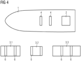
- Fig. 4 shows a plan view of a ship 1 and a group of different tanks 3.1, 3.2, 3.3 having different shapes or volumes according to an embodiment.
- the ship 1 comprises a mounting device 4 being configured to mount any tank 3.1, 3.2, 3.3 of the group, wherein each tank 3.1, 3.2, 3.3 being partly filled with the fluid 5 is configured to provide different natural frequencies of the rolling motion of the loaded ship 1. For example, depending on the load 2, one out of the group of different tanks 3.1, 3.2, 3.3 is selected and partly filled with the fluid 5 so that the natural frequency of the rolling motion of the loaded ship 1 including the selected tank 3.1, 3.2 or 3.3 is adjusted to the predetermined rolling frequency.
- Each tank 3.1, 3.2, 3.3 can be provided with an adaptor 6 which is configured to be mounted to the mounting device 4.
- the mounting device 4 is configured to interchangeably mount each tank 3.1, 3.2, 3.3 of the group so that a modular system is achieved.
- the present invention is particularly useful in cases, where the load 2 is a heavy component of a wind turbine, such as a tower, a nacelle or a blade.
- the method comprises steps of loading a load 2 onto the ship 1, and mounting at least one tank 3 to the ship 1.
- the tank 3 is partly filled by a fluid 5 with the fluid level L so that a natural frequency of a rolling motion of the loaded ship 1 including the mounted tank 3 is adjusted to a predetermined rolling frequency.
- the rolling motion of the ship 1 is its motion along a longitudinal axis X of the ship, which can be caused by the sea waves.
- the filled tank 3 has a natural sloshing frequency or period, which affects and thus adjusts the predetermined rolling frequency of the entire loaded ship 1.
- the sloshing period of the filled tank 3 is different, preferably significantly away from a rolling frequency of the loaded ship 1 without the tank 3 or with the unfilled tank 3.
- the method can further comprise a step of determining or measuring an initial natural rolling frequency f 1 of the rolling motion of the ship 1 with the loaded load 2, for example without the tank 3 or with the unfilled tank 3.
- This initial natural rolling frequency f 1 can be calculated by a well-known formula for example by taking the load 2, a mass of the ship 1 and a position of a center of gravity of the ship 1 into account.
- the initial natural rolling frequency f 1 of the rolling motion of the ship 1 can be obtained by experiments which are carried out in advance.
- the method further comprises a step of estimating an expected wave frequency f exp of the sea. This can be done by using an ocean report or statistical data, for instance.
- a predetermined fluid level L is provided in the tank 3 to obtain a predetermined rolling frequency f 2 of the rolling motion of the ship 1 with the loaded load 2 so that a difference
- the sloshing frequency of the filled tank 3 and the predetermined rolling frequency f 2 of the ship 1 including the loaded load 2 and the tank 3 having the predetermined fluid level L is significantly away from the estimated expected wave frequency f exp of the sea so that the rolling movement of a ship 1 is well damped.
- the method further comprises steps of filling and/or discharging the tank 3 to obtain a pre-determined fluid level L, wherein the predetermined fluid level L is configured to adjust the natural frequency of the rolling motion of the loaded ship 1 including the tank 3 with the predetermined fluid level L to the predetermined rolling frequency.
- the method further comprises steps of adjusting a density of the fluid 5 within the tank 3 to a predetermined density, wherein the predetermined density is configured to adjust the natural frequency of the rolling motion of the loaded ship 1 including the filled tank 3 to the predetermined rolling frequency.
- the method further comprises steps of selecting a tank 3.1, 3.2 or 3.3 having a predetermined shape or volume, the selected tank 3.1, 3.2 or 3.3, when filled with the fluid 5 with a predetermined fluid level L, is configured to adjust the natural frequency of the rolling motion of the loaded ship 1 including the selected tank 3.1, 3.2 or 3.3 to the predetermined rolling frequency, and providing the predetermined fluid level L in the selected tank 3.1, 3.2 or 3.3.
- one of the tanks 3.1, 3.2 or 3.3 can be selected to adjust the natural frequency of the rolling motion of the loaded ship 1 to the predetermined rolling frequency.
- the method further comprises steps of selecting a predetermined number of the tanks 3, wherein the selected number of the tanks 3, when filled with the fluid 5 with predetermined fluid levels L, is configured to adjust the natural frequency of the rolling motion of the loaded ship 1 including the selected number of the tanks 3 to the predetermined rolling frequency, and providing the fluid levels L in the selected number of the tanks 3.
- the selected number of prefilled tanks 3 can be mounted.
- the tanks 3 can be mounted in an empty state to the ship 1, and only the selected number of the tanks 3 is filled with the fluid 5.
- the tank 3 is preferably filled between 30% and 70%, more preferred between 40% and 50%, with the fluid 5. Because the tank 3 is not fully filled, a sloshing motion of the fluid 5 is possible.
- the fluid 5 is or comprises water, preferably sea water.
Landscapes
- Chemical & Material Sciences (AREA)
- Engineering & Computer Science (AREA)
- Combustion & Propulsion (AREA)
- Mechanical Engineering (AREA)
- Ocean & Marine Engineering (AREA)
- Vibration Prevention Devices (AREA)
Abstract
It is described a method of damping a rolling movement of a ship (1). The method comprises loading a load (2) onto the ship (1); and mounting at least one tank (3) to the ship (1), the tank (3) is partly filled by a fluid (5) so that a natural frequency of a rolling motion of the loaded ship (1) including the mounted tank (3) is adjusted to a predetermined rolling frequency.
Description
- The present invention relates to a method of damping a rolling movement of a loaded ship, and to a ship comprising a device configured to damp a rolling movement of the loaded ship. In the context of the present invention, the general expression "ship" also comprises barges and vessels amongst others.
- Sea waves and strong wind conditions may lead to heavy rolling motions of a ship. The rolling motion is an oscillating movement of the ship around the longitudinal axis of the ship. This might lead to weather restricted operations for loading and discharging a cargo, when the ship is not docked in a sheltered environment. These weather restrictions can be very severe, making the operational durations of projects using a barge transport solution very long and costly. If the operational performance can be significantly improved, a lot of time and expense could be saved.
- For example, the specific issue of operability of barges delivering wind turbine components to installation vessels offshore, is the limiting operation for a wind turbine installation. In particular for projects in USA, only a few vessels can sail back and forth directly for loading components in a harbour due to the Jones Act requirement. Wind turbines must be feed offshore to the installation vessel and lifted off the feeder barge by a jacked up wind turbine installation vessel (WTIV). The movement of the barge while lifting heavy components is highly challenging.
- Complex lifting tools, dynamic motion compensation devices, and free surfaces in hull tanks are used to cope with the rolling motions so far. In general, tools are developed to remove or compensate for the individual motions of an object loaded on a barge, rather than reducing the movements of the entire barge.
- There may be a need for efficiently and readily damping the rolling motion of a ship. This need may be met by the subject matters according to the independent claims. The present invention is further developed as set forth in the dependent claims.
- According to a first aspect of the invention, a method of damping a rolling movement of a ship is provided. The method comprises steps of loading a load onto the ship; and mounting at least one tank to the ship, the tank is partly filled by a fluid so that a natural frequency of a rolling motion of the loaded ship including the mounted tank is adjusted to a predetermined rolling frequency.
- The filled tank has a natural sloshing frequency or period, which affects and thus adjusts the predetermined rolling frequency of the entire loaded ship. The sloshing period of the filled tank is different, preferably significantly away from a rolling frequency of the loaded ship without the tank or with an unfilled tank, and preferably significantly away from an estimated expected wave frequency of the sea.
- For example, the ship can be a feeder barge. One or more large tanks of certain shapes can be arranged on a deck of a barge in a manner that they can be relatively easily removed. The tanks shall exhibit their sloshing period significantly away from the roll period of the loaded barge.
- When the barge is loaded and in a sea state, it has reactions to the waves. Without using the tank, these reactions would be be very significant and create high difficulty in handling items on a barge in poor weather conditions. Every floating vessel has a natural frequency for its motions in 6 degrees of freedom. The most significant of these is the roll motion about the barge's longitudinal axis. When the natural frequency is nearby the frequency the waves encounter the barge, high motions are usually experienced which leads to large forces to sea fasten cargo and limitations to the wave height at which loading and discharge operations can occur. By enabling a very high amount of damping to the rolling motion of a barge according to the present invention, the influence of the sea state is dramatically less.
- So far, tools have been developed to remove or compensate for the motions of an object loaded on a barge, rather than the reduce the movements of the barge. The purpose of using large tanks with a geometry specifically arranged to allow tuning the natural period of the barge to avoid coincidence with the prevailing sea state in accordance with the present invention means that the barges motions are wholistically reduced, whereas prior art compensation devices try to compensate for the local and relative movements of the loaded items loaded on the barge to keep the items approximately stationary. These prior art compensation devices also have limitations on their capabilities, if used in conjunction with roll damping of the barge, whereas the present invention is significantly more effective.
- In an embodiment, the method further comprises steps of determining or measuring an initial natural rolling frequency of the rolling motion of the ship with the loaded load, estimating an expected wave frequency of the sea, and providing a predetermined fluid level in the tank to obtain the predetermined rolling frequency of the rolling motion of the ship with the loaded load so that a difference between the initial natural rolling frequency and the estimated expected wave frequency is smaller than a difference between the predetermined rolling frequency and the estimated expected wave frequency.
- The step of determining or measuring the natural frequency can be made by calculations based on a well-known formula which for example take the load, a mass of the ship and a position of a center of gravity of the ship, etc. into account. Alternatively, the natural frequency of the rolling motion of the ship can be obtained by experiments which are carried out in advance. The step of estimating the expected wave frequency of the sea can be done by using an ocean report or statistical data, for instance.
- In an embodiment, the method further comprises at least one of the following: filling and/or discharging the tank to obtain a predetermined fluid level, the predetermined fluid level is configured to adjust the natural frequency of the rolling motion of the loaded ship including the mounted tank to the predetermined rolling frequency; and adjusting a density of the fluid within the tank to a predetermined density, the predetermined density is configured to adjust the natural frequency of the rolling motion of the loaded ship including the mounted tank to the predetermined rolling frequency. In these embodiments, the tank can be an integral part of the ship which does not have to be detached or replaced.
- In an embodiment, the method further comprises steps of selecting a tank having a predetermined shape or volume, the selected tank, when filled with the fluid with a predetermined fluid level, is configured to adjust the natural frequency of the rolling motion of the loaded ship including the selected tank to the predetermined rolling frequency, and providing the predetermined fluid level in the selected tank. Depending on the load of the loaded ship, an optimized tank out of the available tanks is selected to adjust the natural frequency of the rolling motion of the loaded ship to the predetermined rolling frequency. In this embodiment, the tank can either be an integral part of the ship which does not have to be detached or replaced, or the selected tank can be mounted to the ship and then filled with the fluid with the predetermined fluid level.
- In an embodiment, the method further comprises steps of selecting a predetermined number of the tanks with predetermined fluid levels, the selected number of the tanks, when filled with the fluid, is configured to adjust the natural frequency of the rolling motion of the loaded ship including the selected number of the tanks to the predetermined rolling frequency, and providing the fluid levels in the selected number of the tanks. In this embodiment, the tanks can either be integral parts of the ship which do not have to be detached or replaced, or the tanks can be mounted to the ship and then filled with the fluid with the predetermined fluid levels.
- In an embodiment, the tank is filled between 30% and 70%, preferably between 40% and 50%, with the fluid. Because the tank is not fully filled, a sloshing motion of the fluid is possible. In an embodiment, the fluid is or comprises water, preferably sea water.
- According to a second aspect of the invention, a ship is provided. The ship is loaded with a load so that the loaded ship has a predetermined natural frequency of a rolling motion. The ship comprises a device configured to damp a rolling movement of the loaded ship, wherein the device comprises at least one tank which is partly filled by a fluid so that the natural frequency of the rolling motion of the loaded ship including the tank is adjusted to the predetermined rolling frequency.
- The second aspect of the present invention achieves the same advantages as the first aspect of the present invention.
- In an embodiment, in a cross section of the tank along a transverse axis of the ship, the tank comprises a central portion and two lateral portions, wherein a surface area of the central portion is smaller than surface areas of each lateral portion. A high sloshing amplitude can be obtained in the lateral portions, while the entire tank is configured to save space due to the smaller central portion. In an embodiment, the cross section of the tank along the transverse axis of the ship can substantially be U-shaped, H-shaped, X-shaped or V-shaped.
- In an embodiment, the ship is configured to mount a group of tanks, wherein the ship comprises a subgroup of the tanks, which is configured to provide the predetermined rolling frequency.
- In an embodiment, the ship comprises a mounting device being configured to mount any tank of a group comprising different tanks having different sizes or shapes, wherein the different tanks being partly filled with the fluid are configured to provide different natural frequencies of the rolling motion of the loaded ship. In an embodiment, the mounting device is configured to interchangeably mount each tank of the group.
- In an embodiment, the load is a component of a wind turbine, for example a tower or tower segment, a nacelle or a blade.
- It has to be noted that embodiments of the invention have been described with reference to different subject matters. In particular, some embodiments have been described with reference to apparatus type claims whereas other embodiments have been described with reference to method type claims. However, a person skilled in the art will gather from the above and the following description that, unless other notified, in addition to any combination of features belonging to one type of subject matter also any combination between features relating to different subject matters, in particular between features of the apparatus type claims and features of the method type claims is considered as to be disclosed with this application.
- The aspects defined above and further aspects of the present invention are apparent from the examples of embodiment to be described hereinafter and are explained with reference to the examples of embodiment. The invention will be described in more detail hereinafter with reference to examples of embodiment but to which the invention is not limited.
- Fig. 1
- shows a perspective view of a ship according to an embodiment;
- Fig. 2
- shows a cross section of a ship and a tank according to an embodiment;
- Fig. 3
- shows a cross section of a ship and tanks according to an embodiment;
- Fig. 4
- shows a plan view of a ship and a group of different tanks according to an embodiment.
- The illustrations in the drawings are schematically. It is noted that in different figures, similar or identical elements are provided with the same reference signs.
-
Fig. 1 shows aship 1 according to an embodiment. Theship 1 is loaded with aload 2 so that the loadedship 1 has a predetermined natural frequency of a rolling motion. Theship 1 comprises a device configured to damp or reduce a rolling movement of the loadedship 1. The device comprises at least onetank 3 which is partly filled by afluid 5 with a fluid level L so that the natural frequency of the rolling motion of the loadedship 1 including thetank 3 is adjusted to the predetermined rolling frequency. - The rolling motion of the
ship 1 is its motion along a longitudinal axis X of the ship, which can be caused by the sea waves. The filledtank 3 has a natural sloshing frequency or period, which affects and thus adjusts the predetermined rolling frequency of the entire loadedship 1. The sloshing period of the filledtank 3 is different, preferably significantly away from a rolling frequency of the loadedship 1 without thetank 3 or with theunfilled tank 3, or significantly away from an estimated expected wave frequency of the sea. -
Fig. 2 shows a cross section of aship 1 and atank 3 along a transverse axis of theship 1 according to an embodiment. In the cross section of thetank 3, thetank 3 comprises acentral portion 32 and twolateral portions 31, 33, wherein a surface area of thecentral portion 32 is smaller than surface areas of eachlateral portion 31, 33. The cross section of thetank 3 along the transverse axis of theship 1 can also be substantially U-shaped, H-shaped, V-shaped or X-shaped. - In a neutral state, the
fluid 5 within the tank has a neutral fluid level L. On the sea, when theship 1 is subjected to the waves, thefluid 5 in thetank 3 is sloshing and exhibits an oscillating sloshing level L1. Due to the specific shape of thetank 3, where the surface area of thecentral portion 32 is smaller than surface areas of eachlateral portion 31, 33, a high sloshing amplitude can be obtained in thelateral portions 31, 33, while theentire tank 3 is configured to save space due to the smallercentral portion 32. For example, the free space above the recessedcentral portion 32 can be used for storage purposes, for example theload 2 could be placed there. The same effect can be achieved, when thetank 3 along the transverse axis of theship 1 is substantially U-shaped, H-shaped, V-shaped or X-shaped. -
Fig. 3 shows a cross section of aship 1 andtanks 3 according to an embodiment. Theship 1 is configured to mount a group oftanks 3, wherein the ship comprises a subgroup of thetanks 3, which is configured to provide the predetermined rolling frequency. In the embodiment ofFig. 3 , theship 1 is configured to mount fourtanks 3 as a maximum. For example, depending on the mass of the loadedload 2, which affects the rolling frequency of theship 1, some of the fourtanks 3 can be removed or remain unfilled to obtain the predetermined rolling frequency of the loadedship 1. -
Fig. 4 shows a plan view of aship 1 and a group of different tanks 3.1, 3.2, 3.3 having different shapes or volumes according to an embodiment. Theship 1 comprises a mounting device 4 being configured to mount any tank 3.1, 3.2, 3.3 of the group, wherein each tank 3.1, 3.2, 3.3 being partly filled with thefluid 5 is configured to provide different natural frequencies of the rolling motion of the loadedship 1. For example, depending on theload 2, one out of the group of different tanks 3.1, 3.2, 3.3 is selected and partly filled with thefluid 5 so that the natural frequency of the rolling motion of the loadedship 1 including the selected tank 3.1, 3.2 or 3.3 is adjusted to the predetermined rolling frequency. Each tank 3.1, 3.2, 3.3 can be provided with anadaptor 6 which is configured to be mounted to the mounting device 4. - Preferably, the mounting device 4 is configured to interchangeably mount each tank 3.1, 3.2, 3.3 of the group so that a modular system is achieved.
- The present invention is particularly useful in cases, where the
load 2 is a heavy component of a wind turbine, such as a tower, a nacelle or a blade. - In the following, a method of damping a rolling movement of a
ship 1 is described. The method comprises steps of loading aload 2 onto theship 1, and mounting at least onetank 3 to theship 1. Thetank 3 is partly filled by afluid 5 with the fluid level L so that a natural frequency of a rolling motion of the loadedship 1 including the mountedtank 3 is adjusted to a predetermined rolling frequency. The rolling motion of theship 1 is its motion along a longitudinal axis X of the ship, which can be caused by the sea waves. The filledtank 3 has a natural sloshing frequency or period, which affects and thus adjusts the predetermined rolling frequency of the entire loadedship 1. The sloshing period of the filledtank 3 is different, preferably significantly away from a rolling frequency of the loadedship 1 without thetank 3 or with theunfilled tank 3. - In an embodiment, the method can further comprise a step of determining or measuring an initial natural rolling frequency f1 of the rolling motion of the
ship 1 with the loadedload 2, for example without thetank 3 or with theunfilled tank 3. This initial natural rolling frequency f1 can be calculated by a well-known formula for example by taking theload 2, a mass of theship 1 and a position of a center of gravity of theship 1 into account. Alternatively, the initial natural rolling frequency f1 of the rolling motion of theship 1 can be obtained by experiments which are carried out in advance. - The method further comprises a step of estimating an expected wave frequency fexp of the sea. This can be done by using an ocean report or statistical data, for instance.
- Thereafter, a predetermined fluid level L is provided in the
tank 3 to obtain a predetermined rolling frequency f2 of the rolling motion of theship 1 with the loadedload 2 so that a difference |f1 - fexp| between the initial natural rolling frequency f1 of the rolling motion of theship 1 including the loadedload 2 and the estimated expected wave frequency fexp is smaller than a difference |f2 - fexp| between the predetermined rolling frequency f2 of the rolling motion of theship 1 including the loadedload 2 and thetank 3 having the predetermined fluid level L, and the estimated expected wave frequency fexp. Preferably, the sloshing frequency of the filledtank 3 and the predetermined rolling frequency f2 of theship 1 including the loadedload 2 and thetank 3 having the predetermined fluid level L is significantly away from the estimated expected wave frequency fexp of the sea so that the rolling movement of aship 1 is well damped. - In an embodiment, the method further comprises steps of filling and/or discharging the
tank 3 to obtain a pre-determined fluid level L, wherein the predetermined fluid level L is configured to adjust the natural frequency of the rolling motion of the loadedship 1 including thetank 3 with the predetermined fluid level L to the predetermined rolling frequency. - In another embodiment, the method further comprises steps of adjusting a density of the
fluid 5 within thetank 3 to a predetermined density, wherein the predetermined density is configured to adjust the natural frequency of the rolling motion of the loadedship 1 including the filledtank 3 to the predetermined rolling frequency. - In an embodiment as shown in
Fig. 4 , the method further comprises steps of selecting a tank 3.1, 3.2 or 3.3 having a predetermined shape or volume, the selected tank 3.1, 3.2 or 3.3, when filled with thefluid 5 with a predetermined fluid level L, is configured to adjust the natural frequency of the rolling motion of the loadedship 1 including the selected tank 3.1, 3.2 or 3.3 to the predetermined rolling frequency, and providing the predetermined fluid level L in the selected tank 3.1, 3.2 or 3.3. Depending on the load of the loadedship 1, one of the tanks 3.1, 3.2 or 3.3 can be selected to adjust the natural frequency of the rolling motion of the loadedship 1 to the predetermined rolling frequency. - In an embodiment as shown in
Fig. 3 , the method further comprises steps of selecting a predetermined number of thetanks 3, wherein the selected number of thetanks 3, when filled with thefluid 5 with predetermined fluid levels L, is configured to adjust the natural frequency of the rolling motion of the loadedship 1 including the selected number of thetanks 3 to the predetermined rolling frequency, and providing the fluid levels L in the selected number of thetanks 3. For example, the selected number ofprefilled tanks 3 can be mounted. Alternatively, thetanks 3 can be mounted in an empty state to theship 1, and only the selected number of thetanks 3 is filled with thefluid 5. - The
tank 3 is preferably filled between 30% and 70%, more preferred between 40% and 50%, with thefluid 5. Because thetank 3 is not fully filled, a sloshing motion of thefluid 5 is possible. Thefluid 5 is or comprises water, preferably sea water. - It should be noted that the term "comprising" does not exclude other elements or steps and "a" or "an" does not exclude a plurality. Also elements described in association with different embodiments may be combined. It should also be noted that reference signs in the claims should not be construed as limiting the scope of the claims.
- Independent of the grammatical term usage, individuals with male, female or other gender identities are included within the term.
Claims (14)
- A method of damping a rolling movement of a ship (1), the method comprising:
loading a load (2) onto the ship (1); and
mounting at least one tank (3) to the ship (1), the tank (3) is partly filled by a fluid (5) so that a natural frequency of a rolling motion of the loaded ship (1) including the mounted tank (3) is adjusted to a predetermined rolling frequency. - The method according to the preceding claim, further comprising steps of:
determining or measuring an initial natural rolling frequency (f1) of the rolling motion of the ship (1) with the loaded load (2);
estimating an expected wave frequency (fexp) of the sea; and providing a predetermined fluid level (L) in the tank (3) to obtain the predetermined rolling frequency (f2) of the rolling motion of the ship (1) with the loaded load (2) so that a difference (|f1 - fexp|) between the initial natural rolling frequency (f1) and the estimated expected wave frequency (fexp) is smaller than a difference (|f2 - fexp|) between the predetermined rolling frequency (f2) and the estimated expected wave frequency (fexp). - The method according to any one of the preceding claims, further comprising at least one of the following:filling and/or discharging the tank (3) to obtain a predetermined fluid level (L), the predetermined fluid level (L) is configured to adjust the natural frequency of the rolling motion of the loaded ship (1) including the mounted tank (3) to the predetermined rolling frequency; andadjusting a density of the fluid (5) within the tank (3) to a predetermined density, the predetermined density is configured to adjust the natural frequency of the rolling motion of the loaded ship (1) including the mounted tank (3) to the predetermined rolling frequency.
- The method according to any one of the preceding claims, further comprising steps of:
selecting a tank (3) having a predetermined shape or volume, the selected tank (3), when filled with the fluid (5) with a predetermined fluid level (L), is configured to adjust the natural frequency of the rolling motion of the loaded ship (1) including the selected tank (3) to the predetermined rolling frequency, and providing the predetermined fluid level (L) in the selected tank (3). - The method according to any one of the preceding claims, further comprising steps of:
selecting a predetermined number of the tanks (3), the selected number of the tanks (3), when filled with the fluid (5) with predetermined fluid levels (L), is configured to adjust the natural frequency of the rolling motion of the loaded ship (1) including the selected number of the tanks (3) to the predetermined rolling frequency, and providing the fluid levels (L) in the selected number of the tanks (3). - The method according to any one of the preceding claims, wherein
the tank (3) is filled between 30% and 70%, preferably between 40% and 50%, with the fluid (5). - The method according to any one of the preceding claims, wherein
the fluid (5) is or comprises water, preferably sea water. - A ship (1) loaded with a load (2) so that the loaded ship (1) has a predetermined natural frequency of a rolling motion, the ship (1) comprising a device configured to damp a rolling movement of the loaded ship (1), the device comprising:
at least one tank (3) which is partly filled by a fluid (5) so that the natural frequency of the rolling motion of the loaded ship (1) including the tank (3) is adjusted to the predetermined rolling frequency. - The ship (1) according to the preceding claim, wherein in a cross section of the tank (3) along a transverse axis of the ship (1), the tank (3) comprises a central portion (32) and two lateral portions (31, 33), wherein a surface area of the central portion (32) is smaller than surface areas of each lateral portion (31, 33).
- The ship (1) according to any one of claims 8 and 9, wherein
the cross section of the tank (3) along the transverse axis of the ship (1) is substantially U-shaped, H-shaped, X-shaped or V-shaped. - The ship (1) according to any one of claims 8 to 10, wherein
the ship (1) is configured to mount a group of tanks (3), wherein the ship comprises a subgroup of the tanks (3), which is configured to provide the predetermined rolling frequency. - The ship (1) according to any one of claims 8 to 11, wherein
the ship (1) comprises a mounting device (4) being configured to mount any tank (3.1, 3.2, 3.3) of a group comprising different tanks (3.1, 3.2, 3.3) having different sizes or shapes, wherein the different tanks (3.1, 3.2, 3.3) being partly filled with the fluid (5) are configured to provide different natural frequencies of the rolling motion of the loaded ship (1). - The ship (1) according to the preceding claim, wherein the mounting device (4) is configured to interchangeably mount each tank (3.1, 3.2, 3.3) of the group.
- The ship (1) according to any one of claims 8 to 13, wherein
the load (2) is a component of a wind turbine.
Priority Applications (4)
| Application Number | Priority Date | Filing Date | Title |
|---|---|---|---|
| EP23190188.5A EP4506239A1 (en) | 2023-08-08 | 2023-08-08 | Method of damping a rolling movement of a ship |
| PCT/EP2024/070092 WO2025031735A1 (en) | 2023-08-08 | 2024-07-16 | Method of damping a rolling movement of a ship |
| EP24743830.2A EP4727834A1 (en) | 2023-08-08 | 2024-07-16 | Method of damping a rolling movement of a ship |
| TW113129766A TWI918065B (en) | 2023-08-08 | 2024-08-08 | Method of damping a rolling movement of a ship |
Applications Claiming Priority (1)
| Application Number | Priority Date | Filing Date | Title |
|---|---|---|---|
| EP23190188.5A EP4506239A1 (en) | 2023-08-08 | 2023-08-08 | Method of damping a rolling movement of a ship |
Publications (1)
| Publication Number | Publication Date |
|---|---|
| EP4506239A1 true EP4506239A1 (en) | 2025-02-12 |
Family
ID=87567529
Family Applications (2)
| Application Number | Title | Priority Date | Filing Date |
|---|---|---|---|
| EP23190188.5A Withdrawn EP4506239A1 (en) | 2023-08-08 | 2023-08-08 | Method of damping a rolling movement of a ship |
| EP24743830.2A Pending EP4727834A1 (en) | 2023-08-08 | 2024-07-16 | Method of damping a rolling movement of a ship |
Family Applications After (1)
| Application Number | Title | Priority Date | Filing Date |
|---|---|---|---|
| EP24743830.2A Pending EP4727834A1 (en) | 2023-08-08 | 2024-07-16 | Method of damping a rolling movement of a ship |
Country Status (2)
| Country | Link |
|---|---|
| EP (2) | EP4506239A1 (en) |
| WO (1) | WO2025031735A1 (en) |
Citations (3)
| Publication number | Priority date | Publication date | Assignee | Title |
|---|---|---|---|---|
| JPH04312686A (en) * | 1991-04-11 | 1992-11-04 | Mitsubishi Heavy Ind Ltd | Separation type vibration damping water-tank |
| WO2009048322A1 (en) * | 2007-10-11 | 2009-04-16 | Itrec B.V. | Vessels with roll damping mechanism |
| FR3127465A1 (en) * | 2021-09-30 | 2023-03-31 | Gaztransport Et Technigaz | Transport vessel comprising an attitude control system not communicating with the sea |
-
2023
- 2023-08-08 EP EP23190188.5A patent/EP4506239A1/en not_active Withdrawn
-
2024
- 2024-07-16 WO PCT/EP2024/070092 patent/WO2025031735A1/en active Pending
- 2024-07-16 EP EP24743830.2A patent/EP4727834A1/en active Pending
Patent Citations (3)
| Publication number | Priority date | Publication date | Assignee | Title |
|---|---|---|---|---|
| JPH04312686A (en) * | 1991-04-11 | 1992-11-04 | Mitsubishi Heavy Ind Ltd | Separation type vibration damping water-tank |
| WO2009048322A1 (en) * | 2007-10-11 | 2009-04-16 | Itrec B.V. | Vessels with roll damping mechanism |
| FR3127465A1 (en) * | 2021-09-30 | 2023-03-31 | Gaztransport Et Technigaz | Transport vessel comprising an attitude control system not communicating with the sea |
Non-Patent Citations (2)
| Title |
|---|
| NAZIRI HARITH ASLAM AHMAD ET AL: "Multi-Stabilizer Devices for Marine Vessel, Design and Control - A Review", 2022 IEEE 9TH INTERNATIONAL CONFERENCE ON UNDERWATER SYSTEM TECHNOLOGY: THEORY AND APPLICATIONS (USYS), IEEE, 5 December 2022 (2022-12-05), pages 1 - 13, XP034313402, DOI: 10.1109/USYS56283.2022.10072471 * |
| OSAMA A. MARZOUK ET AL: "Control of ship roll using passive and active anti-roll tanks", OCEAN ENGINEERING, vol. 36, no. 9-10, 1 July 2009 (2009-07-01), AMSTERDAM, NL, pages 661 - 671, XP055375560, ISSN: 0029-8018, DOI: 10.1016/j.oceaneng.2009.03.005 * |
Also Published As
| Publication number | Publication date |
|---|---|
| EP4727834A1 (en) | 2026-04-22 |
| WO2025031735A1 (en) | 2025-02-13 |
| TW202513409A (en) | 2025-04-01 |
Similar Documents
| Publication | Publication Date | Title |
|---|---|---|
| CN101909982B (en) | Systems and methods for active and passive stabilization of ships | |
| EP0975513B1 (en) | Floating barge-platform and method of assembly | |
| EP2528805B1 (en) | Maintenance of an offshore wind farm making use of an assembly of a floating harbour ship and a plurality of shuttle vessels | |
| KR102417737B1 (en) | Marine vessels for the production and storage of hydrocarbon products | |
| WO2010059059A1 (en) | Device for floating production of lng and method for converting a lng-carrier to such a device | |
| CN115367071A (en) | Simulation and calibration optimization method, storage medium and equipment for ship launching process in dock | |
| KR100466881B1 (en) | A cargo-handling apparatus for operation at both side of ship | |
| KR102205732B1 (en) | Device for connecting two boats | |
| US5501563A (en) | Bulk material loading and unloading facility for sea-going ships | |
| US4753185A (en) | Floating vessels | |
| WO2025031735A1 (en) | Method of damping a rolling movement of a ship | |
| TWI918065B (en) | Method of damping a rolling movement of a ship | |
| Fonseca et al. | Hydrodynamic model tests with a large floating hydrocarbon storage facility | |
| WO2013112715A1 (en) | System and method for offshore loading of cargo vessels | |
| KR20180051852A (en) | Fixed LNG Production, Storage, and Offloading Unit for Nearshore | |
| US8915203B2 (en) | Transporting liquefied natural gas (LNG) | |
| KR101263247B1 (en) | Mobile harbor | |
| KR20100124626A (en) | Mobile harbor using vibration isolation for positioning platform | |
| KR101166714B1 (en) | Mobile Harbor System and Cargo Handling Method Using the System | |
| Lin et al. | Caisson Breakwater for LNG and Bulk Terminals: A Study on Limiting Wave Conditions for Caisson Installation | |
| KR101166716B1 (en) | Mobile Harbor System and Cargo Handling Method Using the System | |
| Crowle et al. | Offshore installation vessels stability considerations | |
| Torres Rodriguez et al. | Offshore Wind Feeder Vessel Voyage Simulations | |
| KR101894298B1 (en) | Mooring apparatus and mooring method | |
| KR20100020351A (en) | Bilge keel and floating offshore structures having the same |
Legal Events
| Date | Code | Title | Description |
|---|---|---|---|
| PUAI | Public reference made under article 153(3) epc to a published international application that has entered the european phase |
Free format text: ORIGINAL CODE: 0009012 |
|
| STAA | Information on the status of an ep patent application or granted ep patent |
Free format text: STATUS: THE APPLICATION HAS BEEN PUBLISHED |
|
| AK | Designated contracting states |
Kind code of ref document: A1 Designated state(s): AL AT BE BG CH CY CZ DE DK EE ES FI FR GB GR HR HU IE IS IT LI LT LU LV MC ME MK MT NL NO PL PT RO RS SE SI SK SM TR |
|
| STAA | Information on the status of an ep patent application or granted ep patent |
Free format text: STATUS: THE APPLICATION IS DEEMED TO BE WITHDRAWN |
|
| 18D | Application deemed to be withdrawn |
Effective date: 20250813 |