EP4506212A1 - Vehicle control device, and overheat protection device - Google Patents
Vehicle control device, and overheat protection device Download PDFInfo
- Publication number
- EP4506212A1 EP4506212A1 EP23784519.3A EP23784519A EP4506212A1 EP 4506212 A1 EP4506212 A1 EP 4506212A1 EP 23784519 A EP23784519 A EP 23784519A EP 4506212 A1 EP4506212 A1 EP 4506212A1
- Authority
- EP
- European Patent Office
- Prior art keywords
- temperature
- information
- vehicle
- outside air
- current
- Prior art date
- Legal status (The legal status is an assumption and is not a legal conclusion. Google has not performed a legal analysis and makes no representation as to the accuracy of the status listed.)
- Pending
Links
Images




Classifications
-
- B—PERFORMING OPERATIONS; TRANSPORTING
- B60—VEHICLES IN GENERAL
- B60R—VEHICLES, VEHICLE FITTINGS, OR VEHICLE PARTS, NOT OTHERWISE PROVIDED FOR
- B60R16/00—Electric or fluid circuits specially adapted for vehicles and not otherwise provided for; Arrangement of elements of electric or fluid circuits specially adapted for vehicles and not otherwise provided for
- B60R16/02—Electric or fluid circuits specially adapted for vehicles and not otherwise provided for; Arrangement of elements of electric or fluid circuits specially adapted for vehicles and not otherwise provided for electric constitutive elements
- B60R16/0207—Wire harnesses
- B60R16/0215—Protecting, fastening and routing means therefor
-
- G—PHYSICS
- G01—MEASURING; TESTING
- G01K—MEASURING TEMPERATURE; MEASURING QUANTITY OF HEAT; THERMALLY-SENSITIVE ELEMENTS NOT OTHERWISE PROVIDED FOR
- G01K3/00—Thermometers giving results other than momentary value of temperature
- G01K3/005—Circuits arrangements for indicating a predetermined temperature
-
- G—PHYSICS
- G01—MEASURING; TESTING
- G01K—MEASURING TEMPERATURE; MEASURING QUANTITY OF HEAT; THERMALLY-SENSITIVE ELEMENTS NOT OTHERWISE PROVIDED FOR
- G01K7/00—Measuring temperature based on the use of electric or magnetic elements directly sensitive to heat ; Power supply therefor, e.g. using thermoelectric elements
- G01K7/42—Circuits effecting compensation of thermal inertia; Circuits for predicting the stationary value of a temperature
- G01K7/427—Temperature calculation based on spatial modeling, e.g. spatial inter- or extrapolation
-
- H—ELECTRICITY
- H02—GENERATION; CONVERSION OR DISTRIBUTION OF ELECTRIC POWER
- H02H—EMERGENCY PROTECTIVE CIRCUIT ARRANGEMENTS
- H02H5/00—Emergency protective circuit arrangements for automatic disconnection directly responsive to an undesired change from normal non-electric working conditions with or without subsequent reconnection
- H02H5/04—Emergency protective circuit arrangements for automatic disconnection directly responsive to an undesired change from normal non-electric working conditions with or without subsequent reconnection responsive to abnormal temperature
-
- H—ELECTRICITY
- H02—GENERATION; CONVERSION OR DISTRIBUTION OF ELECTRIC POWER
- H02H—EMERGENCY PROTECTIVE CIRCUIT ARRANGEMENTS
- H02H6/00—Emergency protective circuit arrangements responsive to undesired changes from normal non-electric working conditions using simulators of the apparatus being protected, e.g. using thermal images
-
- H—ELECTRICITY
- H02—GENERATION; CONVERSION OR DISTRIBUTION OF ELECTRIC POWER
- H02H—EMERGENCY PROTECTIVE CIRCUIT ARRANGEMENTS
- H02H7/00—Emergency protective circuit arrangements specially adapted for specific types of electric machines or apparatus or for sectionalised protection of cable or line systems, and effecting automatic switching in the event of an undesired change from normal working conditions
- H02H7/22—Emergency protective circuit arrangements specially adapted for specific types of electric machines or apparatus or for sectionalised protection of cable or line systems, and effecting automatic switching in the event of an undesired change from normal working conditions for distribution gear, e.g. bus-bar systems; for switching devices
- H02H7/226—Emergency protective circuit arrangements specially adapted for specific types of electric machines or apparatus or for sectionalised protection of cable or line systems, and effecting automatic switching in the event of an undesired change from normal working conditions for distribution gear, e.g. bus-bar systems; for switching devices for wires or cables, e.g. heating wires
-
- B—PERFORMING OPERATIONS; TRANSPORTING
- B60—VEHICLES IN GENERAL
- B60R—VEHICLES, VEHICLE FITTINGS, OR VEHICLE PARTS, NOT OTHERWISE PROVIDED FOR
- B60R16/00—Electric or fluid circuits specially adapted for vehicles and not otherwise provided for; Arrangement of elements of electric or fluid circuits specially adapted for vehicles and not otherwise provided for
- B60R16/02—Electric or fluid circuits specially adapted for vehicles and not otherwise provided for; Arrangement of elements of electric or fluid circuits specially adapted for vehicles and not otherwise provided for electric constitutive elements
- B60R16/023—Electric or fluid circuits specially adapted for vehicles and not otherwise provided for; Arrangement of elements of electric or fluid circuits specially adapted for vehicles and not otherwise provided for electric constitutive elements for transmission of signals between vehicle parts or subsystems
- B60R16/0237—Electric or fluid circuits specially adapted for vehicles and not otherwise provided for; Arrangement of elements of electric or fluid circuits specially adapted for vehicles and not otherwise provided for electric constitutive elements for transmission of signals between vehicle parts or subsystems circuits concerning the atmospheric environment
Definitions
- the present invention relates to a vehicle control device and an overheat protection device.
- a method of achieving an overheat protection function for a conventional wire harness using a semiconductor switch using a power semiconductor and a temperature estimation technique for the wire harness is used recently. This method protects the wire harness by detecting a current value flowing through the wire harness, estimating a temperature rise in the wire harness using the current value, and interrupting (turning off) the semiconductor switch.
- Patent Literature 1 describes such an overheat protection technology using temperature estimation of a semiconductor switch and a wire harness. This Patent Literature 1 describes. "At every predetermined time, a flowing current is detected, a current power line temperature is estimated using the flowing current, and the current power line temperature is compared with an allowable upper limit temperature of the power line. Even when the power line temperature rises due to a short current that repeats on/off, it is possible to certainly detect the temperature rise and to interrupt the flowing current before the power line reaches a smoking temperature, thereby preventing smoking from the power line.” Citation List
- Patent Literature 1 Japanese Unexamined Patent Application Publication No. 2009-130944
- a wire harness for a power source located in a vehicle cabin of a vehicle may be wired in a shielded space partitioned by a vehicle body material and an inner lining in the vehicle cabin.
- a shielded space includes, for example, a vehicle cabin ceiling, a door panel interior, a trunk room, and the like.
- the vehicle cabin ceiling is provided with a wire harness for a room lamp, a motor for an electric roof, and the like.
- the door interior is provided with a wire harness for a power window motor, an electric door mirror motor, a door lock actuator, and the like.
- the environmental temperature of the environment in which the wire harness is installed is complicated due to an influence of heat inflow by solar radiation, an outside air temperature, and an inside air temperature of the vehicle cabin.
- temperature of the wire harness was estimated by computing a temperature rise value caused by self-heating of the wire harness to which a current is applied and adding the temperature rise value to a reference temperature of the environment in which the wire harness is provided.
- an error in the reference temperature can lead to a wrong estimated temperature, making it difficult to interrupt the current at an appropriate temperature.
- the estimated temperature of the wire harness is higher than an actual temperature, an amount of the available current decreases, causing a sudden current interruption. To the contrary, when the estimated temperature is lower than the actual temperature, the current cannot be interrupted properly even if the wire harness is overheated.
- the temperature information can be different from that inside the vehicle cabin.
- the environmental temperature can be more different from the temperature inside the vehicle cabin or the outside air temperature, which increases the estimated temperature error due to the temperature rise caused by the solar radiation. Therefore, there is a need for properly estimating the environmental temperature of the environment in which the wire harness is provided, which is the basis of estimating the temperature of the wire harness.
- the present invention has been made in view of such a situation, and aims to properly estimate a temperature of a lead wire.
- a vehicle control device includes: a current detecting unit that detects a current flowing through a lead wire and outputs a current detection value; a current interrupting unit that interrupts the current flowing through the lead wire; and a computing unit that computes a temperature rise value caused by Joule heat in the lead wire using the current detection value, estimates an environmental temperature of the environment in which the lead wire is wired based on the temperature rise value, outside air temperature information of a vehicle, inside air temperature information in the vehicle cabin, and solar radiation information, and determines whether to output a current interrupting instruction to the current interrupting unit based on the temperature of the lead wire estimated using the environmental temperature.
- Fig. 1 is a diagram showing a basic configuration of an overheat protection system 1 for a wire harness 5.
- the overheat protection system 1 is an example of a vehicle control device to which the present invention is applied.
- the overheat protection system 1 controls a current I supplied to a load device 6 through the wire harness 5.
- the wire harness 5 is arranged along an inside of a shielded space 23 of a pillar and a ceiling of a vehicle 20 shown in Fig. 3 to be described later.
- the load device 6 is an actuator that operates the vehicle 20 via a motor, a solenoid, and the like. Electric power for the load device 6 is supplied from a battery 2 loaded on the vehicle 20.
- the current detecting element 3 detects a current value of the current I flowing through the wire harness 5.
- the current detecting unit detects the current flowing through the lead wire (wire harness 5) and outputs a current detection value.
- the current detecting element 3 includes a shunt resistor connected to the power source supply path in series, and is able to detect the current I based on a voltage drop in the shunt resistor. Moreover, the current detecting element 3 can also detect the current I using a current sensing power MOSFET (Metal Oxide Semiconductor Field Effect Transistor) as the interrupting element 4.
- MOSFET Metal Oxide Semiconductor Field Effect Transistor
- the current interrupting unit interrupts the current flowing through the lead wire (wire harness 5).
- This interrupting element 4 is a semiconductor switch such as a power MOSFET, and has a function of interrupting the power supply to the load device 6 via the wire harness 5.
- the overheat protection system 1 includes a computing element 7.
- a computing unit (computing element 7) computes a temperature rise value caused by Joule heat in the lead wire (wire harness 5) using the current detection value. Then, the computing unit (computing element 7) estimates an environmental temperature Ta of the environment in which the lead wire (wire harness 5) is wired based on the temperature rise value, outside air temperature information 12a of the vehicle 20, inside air temperature information 11a in the vehicle cabin, and solar radiation information 13a. Furthermore, the computing unit (computing element 7) determines whether to output a current interrupting instruction to the current interrupting unit (interrupting element 4) based on the temperature of the lead wire (wire harness 5) estimated using the environmental temperature Ta.
- the computing element 7 is used as an example of an overheat protection device that protects the wire harness 5 from overheat.
- the computing element 7 includes a conducting wire temperature estimating unit 8, an interruption determining unit 9, and an environmental temperature estimating unit 10.
- a DSP Digital signal processor
- an FPGA Field Programmable gate array
- the computing element 7 estimates the environmental temperature Ta of the environment in which the wire harness 5 is installed, and estimates the temperature of the wire harness 5 based on the environmental temperature Ta and the Joule heat generated in the wire harness 5. The computing element 7 then determines whether to interrupt the power supply to the load device 6 through the wire harness 5.
- the computing unit estimates the temperature of the lead wire (wire harness 5) by adding the environmental temperature Ta in the shielded space (shielded space 23) to the temperature rise value.
- the conducting wire temperature estimating unit 8 estimates the temperature of the wire harness 5 by calculating the temperature rise value using current information input from the current detecting element 3 and adding an estimated value of the environmental temperature Ta of the environment in which the wire harness 5 is installed to the temperature rise value.
- a heat value of the wire harness 5 to be estimated and a heat dissipation characteristics model are used. A specific example of a method of estimating the temperature of the wire harness 5 will be described later.
- the interruption determining unit 9 determines to interrupt the current if the temperature estimation value from the conducting wire temperature estimating unit 8 is higher than a predetermined threshold, and outputs an interruption signal to the interrupting element 4.
- the interrupting element 4 interrupts the current I flowing through the wire harness 5 based on the interrupting instruction from the interruption determining unit 9.
- the environmental temperature estimating unit 10 estimates the environmental temperature Ta of the environment in which the wire harness 5 is installed based on the inside air temperature information 11a of the vehicle 20, the outside air temperature information 12a, and the solar radiation information 13a.
- the environmental temperature Ta estimated by the environmental temperature estimating unit 10 is output to the conducting wire temperature estimating unit 8.
- the computing unit obtains the outside air temperature information 12a from an outside air temperature detecting unit (outside air temperature sensor 12) installed in the vehicle 20, obtains the inside air temperature information 11a from an inside air temperature detecting unit (inside air temperature sensor 11) installed in the vehicle 20, and obtains the solar radiation information 13a from a solar radiation detecting unit (solar radiation sensor 13) installed in the vehicle 20.
- the inside air temperature information 11a can be obtained from the inside air temperature sensor 11 that detects the temperature inside the vehicle cabin.
- the inside air temperature sensor 11 is installed in a location shielded from the solar radiation such as an interior of an instrument panel in the vehicle cabin.
- a thermistor used for controlling an air conditioner can be used as the inside air temperature sensor 11.
- the outside air temperature information 12a can be obtained from the outside air temperature sensor 12 loaded on the vehicle 20.
- the outside air temperature sensor 12 is desirably installed at a location not affected by a heat source of the vehicle 20 such as a thermistor for engine control that is installed in a front part of the vehicle 20.
- the solar radiation information 13a can be obtained from the solar radiation sensor 13 for controlling the air conditioner, for example.
- the solar radiation sensor 13 is installed on a dashboard in a vehicle cabin front part and detects the solar radiation entering through a windshield by a photodiode.
- Another example of the solar radiation sensor 13 may be a sensor used for an auto head light.
- the solar radiation information 13a can also be obtained from brightness information or the like from a front camera, a side camera, a rearview camera loaded on the vehicle 20 for driving assistance.
- the solar radiation.information can be obtained via an in-vehicle network such as a CAN (Controller Area Network).
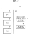
- Fig. 2 is a block diagram showing an example hardware configuration of the computing device 50.
- the computing device 50 is an example of hardware used as a computer operable as the overheat protection system 1 according to this embodiment.
- the overheat protection system 1 according to this embodiment achieves an environmental temperature estimating method performed by each functional block shown in Fig. 2 in combination by the computing device 50 (computer) executing a program.
- the microcomputer, the DSP, and the FPGA described above may be used as the computing device 50.
- the computing device 50 includes a CPU (Central Processing Unit) 51, a ROM (Read Only Memory) 52, and a RAM (Random Access Memory) 53 respectively connected to a bus 54. Furthermore, the computing device 50 includes a nonvolatile storage 55 and a network interface 56.
- a CPU Central Processing Unit
- ROM Read Only Memory
- RAM Random Access Memory
- the CPU 51 reads a program code of software that achieves each function according to this embodiment from the ROM 52, loads the program code to the RAM 53, and executes the program code. Variables and parameters generated in the middle of arithmetic processing by the CPU 51 are temporarily written into the RAM 53, and these variables and parameters and the like are read by the CPU 51 as appropriate.
- an MPU Micro Processing Unit
- an HDD Hard Disk Drive
- an SSD Solid State Drive
- a flexible disk an optical disk, a magnetooptical disk, a CD-ROM, a CD-R, a magnetic tape, a nonvolatile memory, or the like is used as the nonvolatile storage 55.
- an OS Operating System
- a program for operating the computing device 50 is recorded in the nonvolatile storage 55.
- the ROM 52 and the nonvolatile storage 55 record therein a program, data, and the like necessary for the CPU 51 to operate, and are used as examples of a computer readable non-transitory storage medium that stores therein the program to be executed by the computing device 50.
- an NIC Network Interface Card
- the network interface 56 allowing for transmitting/receiving various data between devices via the CAN connected to a terminal of the NIC, a dedicated line, and the like.
- Fig. 3 is a diagram showing an example in which the overheat protection system 1 is applied to the wire harness provided to a ceiling of the vehicle 20 according to the present embodiment.
- Fig. 3 is a cross-sectional view of the vehicle 20 as seen from its side.
- a room lamp installed on the ceiling inside the vehicle cabin is used as the load device 6.
- Electric power is supplied from the battery 2 installed in the front part of the vehicle 20 to a power source distribution unit 14 installed in the vehicle cabin (an example of an on-board power source distribution device).
- the load device 6 is then driven by the power supplied from the power source distribution unit 14 via the wire harness 5.
- the power source distribution unit 14 is constituted as the overheat protection system 1 shown in Fig. 1 .
- the overheat protection system 1 and the overheat protection device are also applicable to the path for supplying a current for the on-board power source distribution device that distributes the power supplied from the battery 2 to each unit in the vehicle 20. Therefore, the power source distribution unit 14 can aggregate various information detected by each sensor, perform temperature estimation on the wire harness 5 in each zone of the vehicle 20, and interrupt power sharing to the load device 6 as needed.
- the wire harness 5 is connected to the load device 6 and the power source distribution unit 14 through the pillar and the ceiling of the vehicle 20.
- the wire harness 5 is provided in a space between a body 21 of the vehicle 20 and an inner lining 22 in the vehicle cabin.
- the body 21 is a portion that receives the solar radiation such as the pillar, the ceiling, the door, and the like of the vehicle 20.
- the current detecting element 3, the interrupting element 4, and the computing element 7 are disposed in the power source distribution unit 14.
- the power source distribution unit 14 estimates the temperature of the wire harness 5 passing through the ceiling of the vehicle 20 and protects the wire harness from the overheat.
- the shielded space 23 is formed between the outside air environment and the inside air environment of the vehicle 20, which is thermally shielded from the outside air environment and the inside air environment and in which the lead wire is wired.
- the environment in which the lead wire (wire harness 5) is wired is the shielded space (shielded space 23) in which the lead wire (wire harness 5) is wired.
- the wire harness 5 is arranged in the shielded space 23 of the ceiling shielded from the inside of the vehicle cabin and the outside of the vehicle. Therefore, the wire harness 5 is placed in an environment in which the environmental temperature changes not only by the outside air temperature and the inside air temperature of the vehicle 20 but also by the solar radiation.
- the environmental temperature estimating unit 10 obtains the outside air temperature information 12a from the outside air temperature sensor 12 installed in the front part of the vehicle 20. Moreover, the environmental temperature estimating unit 10 obtains the inside air temperature information 11a from the inside air temperature sensor 11 installed in the vehicle cabin. Furthermore, the environmental temperature estimating unit 10 obtains the solar radiation information 13a from the solar radiation sensor 13 installed inside the instrument panel in the vehicle cabin. The environmental temperature estimating unit 10 estimates the environmental temperature Ta in the shielded space 23 in which the wire harness 5 is installed based on these three pieces of information.
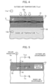
- Fig. 4 is a diagram showing a general form of the shielded space 23 in which the wire harness 5 is installed.
- the shielded space (shielded space 23) is formed between the outside air environment of the vehicle 20 and the inside air environment of the vehicle 20, which is thermally shielded from the outside air environment and the inside air environment and in which the lead wire (wire harness 5) is wired. Furthermore, the wire harness 5 is provided in the shielded space 23 shielded by the body 21 of the a and the inner lining 22 in the vehicle cabin.
- the outside of the body 21 is the outside air environment
- the inside of the inner lining 22 is the inside air environment.
- the outside air temperature information 12a is the temperature information of the outside air environment
- the inside air temperature information 11a is the temperature information of the inside air environment.
- the environmental temperature estimating unit 10 shown in Fig. 1 estimates the environmental temperature Ta in the shielded space 23 using the inside air temperature information 11a, the outside air temperature information 12a, and the solar radiation information 13a.
- Fig. 5 is a diagram showing a heat inflow in the shielded space 23 as an equivalent thermal circuitry.
- Fig. 5 shows a principle by which the environmental temperature estimating unit 10 estimates the environmental temperature Ta in the shielded space 23.
- the outside air temperature in the outside air environment is denoted by a voltage source Tout
- the inside air temperature in the outside air environment is denoted by a voltage source Tin
- the shielded space 23 is denoted by a heat capacity C
- the heat inflow Qs caused by the solar radiation is denoted by a current source.
- the environmental temperature estimating unit 10 estimates the environmental temperature in the shielded space (shielded space 23) by adding the temperature rise value based on the solar radiation information 13a to a weighted average value of the inside air temperature information 11a and the outside air temperature information 12a.
- the formula (1) indicates that the environmental temperature estimating unit 10 can estimate the environmental temperature Ta by adding the temperature rise caused by the heat inflow Qs due to the solar radiation to the weighted average value corresponding to the heat resistance R1 and the heat resistance R2 of the outside air temperature Tout and the inside air temperature Tin, respectively.
- Fig. 6 shows a block diagram of an estimating operation in the environmental temperature estimating unit 10 using the above model formula (1).
- the environmental temperature estimating unit 10 includes a first term computing unit 31 and a second term computing unit 32 for the model formula (1).
- the first term computing unit 31 calculates the first term of the formula (1) using the inside air temperature information 11a (Tin) and the outside air temperature information 12a (Tout) as inputs.
- the second term computing unit 32 calculates the second term of the formula (1) using the heat inflow Qs due to the solar radiation, the heat resistance R1 of the body 21 of the vehicle 20, and the heat resistance R2 of the inner lining 22 as inputs.
- the environmental temperature estimating unit 10 estimates the environmental temperature Ta by adding an arithmetic result of the first term computing unit 31 and an arithmetic result of the second term computing unit 32, and outputs the environmental temperature Ta to the conducting wire temperature estimating unit 8.
- the computing unit sets the weighted average value of the heat resistance R1 and the heat resistance R2 of the outside air temperature Tout and the inside air temperature Tin, respectively, according to the quality of the body material of the vehicle 20 that shields between the outside air environment and the shielded space (shielded space 23) and the quality of an inner lining material that shields between the inside air environment and the shielded space (shielded space 23).
- the heat resistance R1, R2 based on the heat conductivity corresponding to the material and structure of the inner lining 22 in the vehicle cabin makes it possible to further improve the precision of the environmental temperature Ta estimated by the environmental temperature estimating unit 10.
- the computing unit sets a coefficient of the solar radiation information 13a according to emissivity of the body material of the vehicle 20 that shields between the outside air environment and the shielded space (shielded space 23). For example, setting the coefficient k to the heat inflow Qs obtained from the solar radiation information 13a in the formula (1) and setting the coefficient k based on the emissivity corresponding to the material quality and color of the body 21 make it possible to further improve the precision of the environmental temperature Ta estimated by the environmental temperature estimating unit 10. It should be noted that the set values of the heat resistance R1, R2, and the coefficient k are preset for each vehicle type at the time of manufacturing the automobiles.
- the environmental temperature estimating unit 10 may use a method of including in advance a table or map data indicative of relationship among the inside air temperature information 11a (Tin), the outside air temperature information 12a (Tout), and the solar radiation information 13a (Qs), and calculating the environmental temperature Ta according to the information.
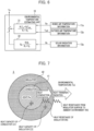
- Fig. 7 is a cross-sectional view of the wire harness 5.
- Fig. 7 shows a heat dissipation path of the wire harness 5.
- the wire harness 5 is constituted by a conductor 41 consisting a conductor in which the current I flows and an insulator 42 that covers the conductor 41.
- the heat generation Pw derived from Joule heat is generated by electric resistance of the conductor.
- the heat generation Pw is stored in a heat capacity C1 of the conductor and conducted to the insulator 42 at the same time.
- heat is stored in a heat capacity C2 of the insulator 42 and conducted to the surface of the insulator 42 via the heat resistance R2 of the insulator 42 at the same time. Then, the heat is dissipated from the surface of the insulator 42 into ambient air of the wire harness 5.
- the heat dissipation into the ambient air of the wire harness 5 is determined by the heat transfer coefficient and heat resistance R3 that is determined by the radiant heat.
- Fig. 8 is a circuit diagram representing a heat dissipation model of the wire harness 5.
- the heat of the heat generation Pw is stored in the heat capacity C2 of the insulator 42 via the heat resistance R2 of the insulator 42. After the heat is stored in the heat capacity C2 of the insulator 42, the heat is then dissipated into the ambient air of the wire harness 5 via the heat resistance R3.
- Fig. 9 is a block diagram showing the equivalent thermal circuitry converted into a transfer function.
- this transfer function an input is denoted by a heat value Pw and an output is denoted by a conductor temperature Tc.
- the conductor temperature Tc of the wire harness 5 is estimated based on the transfer function shown in Fig. 9 .
- the environmental temperature Ta in Fig. 9 is the temperature Ta in the shielded space 23 in which the wire harness 5 is installed as described above.
- the temperature Tc of the wire harness 5 can be estimated by adding a temperature rise value ⁇ Tc caused by Joule heat in the wire harness 5 on the basis of the detected current value detected by the current detecting element 3 to the temperature Ta in the shielded space 23.
- the computing element 7 in the overheat protection system 1 can estimate the temperature of the wire harness 5 based on the outside air temperature Tout of the vehicle 20, the inside air temperature Tin in the vehicle cabin, and the solar radiation information 13a (Qs). Therefore, it is possible to estimate the environmental temperature Ta in the shielded space 23 affected by the solar radiation without adding a new temperature sensor in the shielded space 23 in which the wire harness 5 is installed. For example, when five wire harnesses 5 are wired in the ceiling of the vehicle 20, a temperature sensor used to be provided to each wire harness 5.
- each wire harness 5 since the environment in which each wire harness 5 is wired is common, it is made possible to estimate the temperatures of respective wire harnesses 5 by the computing element 7 estimating the environmental temperature Ta at only one location. In this manner, the environmental temperature estimating unit 10 appropriately estimating the environmental temperature Ta prevents an error between the estimated temperature of the wire harness and the actual temperature.
- the environmental temperature estimating unit 10 obtains the environmental temperature Ta used for the temperature estimation of the wire harness 5 with a low cost and a high precision, the temperature estimation precision of the wire harness 5 is improved. Since the conducting wire temperature estimating unit 8 can appropriately estimate the temperature of the wire harness 5, it is made possible for the interruption determining unit 9 to appropriately interrupt the current flowing through the wire harness 5 at the time of the overcurrent. This makes it possible to certainly detect the overtemperature of the wire harness and interrupt the overcurrent to the load device 6 even if the battery 2 does not excessively limit the current suppliable to the load device 6. Moreover, since the temperature estimation precision of the wire harness 5 is improved, it is made possible to relax a design margin and design the wire harness 5 thinner. This makes it possible to reduce the weight and cost of the wire harness 5 wired in the vehicle 20.
- the overheat protection system 1 allows for replacement of a protection circuit that uses the conventional fuse and relay. Moreover, since temperature monitoring of the wire harness 5 is possible, it is made possible for the overheat protection system 1 to disperse current load on a power network for supplying electric power to each unit.
- the present invention is not limited thereto.
- the present invention can also be applied to such a wire harness 5 that supplies power to a load device such as a map lamp disposed on the ceiling in the vehicle cabin, a digital room mirror, an electric roof, a flashing light, a LiDAR (Light Detection and Ranging) and a camera for outside view recognition.
- the present invention is also applicable to the wire harness 5 that transmits electric power, such as a solar panel disposed on the top surface of the vehicle 20.
- the present invention is also applicable to the wire harness 5 provided in this shielded space 23.
- the shielded space 23 may be disposed near a brake, for example.
- the load device 6 used in such a location includes, for example, a power window, an electric door mirror, a side camera, a door lock actuator, a turn signal lamp, a stop lamp, a rear wiper actuator, a license plate lamp, and the like.
- the present invention can also be applied to the wire harness 5 for supplying electric power to these load devices 6.
- the present invention can also be applied to temperature estimation in the trunk room separate from the vehicle cabin.
- the computing element 7 may check the temperature of the wire harness 5 estimated by the method of this embodiment with the temperature obtained from the temperature sensor already provided to the wire harness 5. If the estimated temperature of the wire harness 5 deviates from the temperature obtained from the temperature sensor already provided to the wire harness 5, a failure of each sensor in the vehicle 20 can be considered.
- the computing element 7 may also obtain the inside air temperature information 11a from a sensor other than the inside air temperature sensor 11. Similarly, the computing element 7 may obtain the outside air temperature information 12a from a sensor other than the outside air temperature sensor 12, and may obtain the solar radiation information 13a from a sensor other than the solar radiation sensor 13.
- the overheat protection system 1 and the overheat protection device can be applied to a path by which an on-vehicle ECU (engine ECU (Electronic Control Unit), zone ECU) supplies a current to an actuator (such as a motor), a fuse, a relay box, and the like.
- the overheat protection system 1 and the overheat protection device may be included in the on-vehicle ECU and the zone ECU.
- the overheat protection system 1 and the overheat protection device according to this embodiment may also be applied to an integrated ECU on the vehicle.
- the integrated ECU preferably aggregates information detected by each sensor, thereby estimating the temperature of the shielded space and the wire harness 5 in each area of the vehicle and transmitting information about the estimated temperature to the power source distribution device.
- the power source distribution device is allowed to take a measure such as to reduce the electric power supplied to the area in which the wire harness 5 is installed, the wire harness 5 having a higher temperature than a reference value, by receiving the temperature information.
- the overheat protection system 1 can also obtain weather information and date and time information from the outside of the vehicle 20 via a radio network such as a mobile phone network and set the outside air temperature information and the solar radiation information using this information.
- Fig. 10 is a block diagram showing an example processing performed by an environmental temperature estimating unit 10A according to the second embodiment. Described here is an example processing of estimating the environmental temperature of the wire harness 5 using information obtained from the outside of the vehicle 20 via the radio network.
- the environmental temperature estimating unit 10A estimates the environmental temperature of the shielded space 23 in which the wire harness is installed using date and time information 17a in addition to the inside air temperature information 11a, the weather information 15, and the GPS information 16a. Therefore, the environmental temperature estimating unit 10A includes an outside air temperature computing unit 33 and a solar radiation computing unit 34 in addition to the first term computing unit 31 and the second term computing unit 32 used in the model formula (1).
- This computing unit calculates a current position of the vehicle 20 based on the GPS information 16a received from a GPS information receiving unit (GPS equipment 16), obtains the weather information 15 at the current position from a radio communication unit (radio communication equipment 18) using the date and time information 17a, and calculates the outside air temperature information 12a and the solar radiation information 13a based on the weather information 15.
- the environmental temperature estimating unit 10A obtains the inside air temperature information 11a from the inside air temperature sensor 11 in the vehicle cabin of the vehicle 20.
- the inside air temperature sensor 11 is installed in a location shielded from the solar radiation such as an interior of the vehicle cabin, and can use a thermistor used for controlling an air conditioner, for example.
- the environmental temperature estimating unit 10A obtains the weather information 15 by receiving a radio wave from a mobile phone base station or the like using the radio communication equipment 18 disposed in the vehicle 20.
- the weather information 15 includes at least information about the weather and temperature with respect to each area.
- the environmental temperature estimating unit 10A obtains the GPS information 16a from the GPS equipment 16 included in an unshown navigation system loaded on the vehicle 20.
- the GPS information 16a is positional information indicative of the current position of the vehicle 20.
- the GPS information 16a is used to identify where the vehicle 20 is travelling.
- the GPS information 16a is input to the outside air temperature computing unit 33 and the solar radiation computing unit 34.
- the date and time information 17a is information about date and time when the vehicle 20 is travelling.
- the date and time information 17a discloses whether the vehicle 20 is travelling in the daytime or at night.
- the environmental temperature estimating unit 10A can not only obtain the date and time information 17a from a clock 17 disposed in the vehicle 20 but also btain the date and time information 17a by receiving the radio wave carrying time information from the outside.
- the outside air temperature computing unit 33 has a function of computing the outside air temperature.
- the weather information 15 is input to the outside air temperature computing unit 33 via the radio communication equipment 18.
- the GPS information 16a is input to the outside air temperature computing unit 33 from the GPS equipment 16 and the date and time information 17a is input to the outside air temperature computing unit 33 from the clock 17.
- the outside air temperature computing unit 33 selects the weather information 15 of an area including the current position of the vehicle 20 based on the GPS information 16a.
- the outside air temperature computing unit 33 also selects the weather information 15 of the area at the current time based on the date and time information 17a.
- the outside air temperature computing unit 33 then computes the outside air temperature of the vehicle 20 based on the weather information 15, the GPS information 16a, and the date and time information 17a, and outputs the computed outside air temperature Tout to the first term computing unit 31.
- the solar radiation computing unit 34 has a function of computing an amount of solar radiation.
- the amount of solar radiation computed by the solar radiation computing unit 34 is calculated as the heat inflow Qs caused by the solar radiation shown in the above formula (1).
- the weather information 15 is input to the solar radiation computing unit 34 via the radio communication equipment 18.
- the GPS information 16a and the date and time information 17a are input to the solar radiation computing unit 34.
- the solar radiation computing unit 34 selects the weather information 15 of the area including a place where the vehicle 20 is travelling based on the GPS information 16a.
- the outside air temperature computing unit 33 also selects the weather information 15 of the area at the current time based on the date and time information 17a.
- the outside air temperature computing unit 33 then computes the amount of solar radiation based on the weather information 15, the GPS information 16a, and the date and time information 17a, and outputs the computed amount of solar radiation to the second term computing unit 32 as the heat inflow Qs caused by the solar radiation.
- the first term computing unit 31 computes the first term of the formula (1) using the inside air temperature information 11a (Tin) and the outside air temperature information 12a (Tout) from the outside air temperature computing unit 33 as inputs.
- the second term computing unit 32 calculates the second term of the formula (1) using the heat inflow Qs due to the solar radiation, the heat resistance R1 of the body 21 of the vehicle 20, and the heat resistance R2 of the inner lining 22 as inputs.
- the environmental temperature estimating unit 10A then estimates the environmental temperature Ta by adding an arithmetic result of the first term computing unit 31 and an arithmetic result of the second term computing unit 32, and outputs the environmental temperature Ta to the conducting wire temperature estimating unit 8.
- the conducting wire temperature estimating unit 8 estimates the temperature of the wire harness 5 based on the estimated value of the environmental temperature Ta, and the interruption determining unit 9 determines to interrupt the current if the temperature estimation value from the conducting wire temperature estimating unit 8 is higher than the predetermine threshold, and outputs the interruption signal to the interrupting element 4.
- the environmental temperature estimating unit 10A calculates the outside air temperature Tout and the amount of solar radiation Qs in which the vehicle 20 is travelling by checking the weather information 15, the GPS information 16a, and the date and time information 17a with one another.
- the environmental temperature estimating unit 10A then computes the weighted average value using the calculated outside air temperature Tout and the inside air temperature information 11a (Tin) as weightings corresponding to the heat resistance R1 and the heat resistance R2.
- the environmental temperature estimating unit 10A computes the temperature rise value due to the heat inflow Qs caused by the calculated solar radiation.
- the environmental temperature estimating unit 10A can now estimate the by adding these arithmetic results.
- the environmental temperature estimating unit 10A shown in Fig. 10 does not require the vehicle 20 to load thereon the solar radiation sensor 13 for obtaining the solar radiation information 13a, and can estimate the environmental temperature Ta even in the vehicle 20 that does not include the solar radiation sensor 13.
- the environmental temperature estimating unit 10A was described to be configured to obtain the outside air temperature information from the weather information, it may be configured to use the outside air temperature sensor 12 loaded on the vehicle 20.
- the environmental temperature estimating unit 10A may be configured to combine a method of obtaining the outside air temperature information 12a from the outside air temperature sensor 12 loaded on the vehicle 20 via the in-vehicle network and a method of obtaining the outside air temperature information 12a via an external network shown in Fig. 10 as appropriate.
- the methods to be combined can be selected according to the presence of the sensor loaded on the vehicle 20, the temperature estimation precision of the wire harness 5, and the like as appropriate.
- the outside air temperature computing unit 33 computes the outside air temperature
- the processing of changing the temperature added to the outside air temperature is assumed depending on whether the vehicle 20 is located in a shady parking lot or travelling on a road. If the vehicle 20 is travelling, an arithmetic operation may be performed using a sum of an average temperature calculated from the weather information 15 in the shady parking lot plus a few degrees as the outside air temperature. In this manner, by the outside air temperature computing unit 33 computing the outside air temperature to be higher, the current through the wire harness 5 can be safely interrupted even if the temperature is estimated to be higher than the actual temperature of the wire harness 5.
- each embodiment described above specifically describes a configuration of the device and the system in detail for better explaining the present invention, and is not limited to necessarily include all the configurations described above. Moreover, it is possible to replace a part of a configuration of the embodiment described herein with a configuration of another embodiment, and it is also possible to add a configuration of one embodiment to a configuration of another embodiment. Furthermore, a part of a configuration of each embodiment can also be added to, deleted from, or replaced with another configuration.
- control lines and information lines assumed to be necessary for the explanation, but not necessarily describes all the control lines and information lines in the product. It may be considered that almost all the configurations are actually connected to one another.
- 1 overheat protection system
- 2 battery
- 3 current detecting element
- 4 interrupting element
- 5 wire harness
- 6 load device
- 7 computing element
- 8 conducting wire temperature estimating unit
- 9 interruption determining unit
- 10 environmental temperature estimating unit
- 11 inside air temperature sensor
- 12 outside air temperature sensor
- 13 solar radiation sensor
- 14 power source distribution unit
- 16 GPS equipment
- 17 clock
- 18 radio communication equipment
- 20 vehicle
- 23 shielded space
- 31 first term computing unit
- 32 second term computing unit
- 33 outside air temperature computing unit
- 34 solar radiation computing unit
Landscapes
- Engineering & Computer Science (AREA)
- Mechanical Engineering (AREA)
- Physics & Mathematics (AREA)
- General Physics & Mathematics (AREA)
- Air-Conditioning For Vehicles (AREA)
- Emergency Protection Circuit Devices (AREA)
- Protection Of Static Devices (AREA)
Abstract
Description
- The present invention relates to a vehicle control device and an overheat protection device.
- Electrical and electronic devices have been using a fuse that is fused by Joule heat from current for protection against overheat from overcurrent. Such a fuse that interrupts the current by thermal fusing requires man-hours for replacing the fuse after the fusing. Moreover, in view of dispersion in the fusing properties of the fuse, it is required to select a thick wire harness (lead wire) in advance. Thus, use of a fuse was a factor of increase in weight and cost of the wire harness.
- Therefore, a method of achieving an overheat protection function for a conventional wire harness using a semiconductor switch using a power semiconductor and a temperature estimation technique for the wire harness is used recently. This method protects the wire harness by detecting a current value flowing through the wire harness, estimating a temperature rise in the wire harness using the current value, and interrupting (turning off) the semiconductor switch.
- In such an overheat protection using a semiconductor switch, since power supply can be resumed by turning the semiconductor switch on once the overcurrent is resolved, replacement of a part such as a fuse is not required. Moreover, since there is no need of considering a variation in fusing as with a conventional fuse, it is possible to use a wire harness thinner than conventional ones, thereby reducing the weight and cost.
-
Patent Literature 1 describes such an overheat protection technology using temperature estimation of a semiconductor switch and a wire harness. ThisPatent Literature 1 describes. "At every predetermined time, a flowing current is detected, a current power line temperature is estimated using the flowing current, and the current power line temperature is compared with an allowable upper limit temperature of the power line. Even when the power line temperature rises due to a short current that repeats on/off, it is possible to certainly detect the temperature rise and to interrupt the flowing current before the power line reaches a smoking temperature, thereby preventing smoking from the power line." Citation List - Patent Literature 1:
Japanese Unexamined Patent Application Publication No. 2009-130944 - A wire harness for a power source located in a vehicle cabin of a vehicle may be wired in a shielded space partitioned by a vehicle body material and an inner lining in the vehicle cabin. Such a shielded space includes, for example, a vehicle cabin ceiling, a door panel interior, a trunk room, and the like. The vehicle cabin ceiling is provided with a wire harness for a room lamp, a motor for an electric roof, and the like. Moreover, the door interior is provided with a wire harness for a power window motor, an electric door mirror motor, a door lock actuator, and the like. In such a shielded space, the environmental temperature of the environment in which the wire harness is installed is complicated due to an influence of heat inflow by solar radiation, an outside air temperature, and an inside air temperature of the vehicle cabin.
- Traditionally, temperature of the wire harness was estimated by computing a temperature rise value caused by self-heating of the wire harness to which a current is applied and adding the temperature rise value to a reference temperature of the environment in which the wire harness is provided. However, an error in the reference temperature can lead to a wrong estimated temperature, making it difficult to interrupt the current at an appropriate temperature. When the estimated temperature of the wire harness is higher than an actual temperature, an amount of the available current decreases, causing a sudden current interruption. To the contrary, when the estimated temperature is lower than the actual temperature, the current cannot be interrupted properly even if the wire harness is overheated.
- As a method of obtaining the reference temperature, it can be conceived to install a temperature sensor near the wire harness to be estimated. However, this method requires installation of the temperature sensor with respect to each of many wire harnesses installed in the vehicle, which increases component costs and man hours for installing the temperature sensor. To suppress such a cost increase, a method of setting information about the temperature sensor or the like in the equipment loaded on the vehicle as the reference temperature can be conceived.
- However, since the wire harness provided inside the ceiling or the door interior of the vehicle is shielded by the inner lining in the vehicle cabin, the temperature information can be different from that inside the vehicle cabin. Moreover, under an environmental condition with strong solar radiation, the environmental temperature can be more different from the temperature inside the vehicle cabin or the outside air temperature, which increases the estimated temperature error due to the temperature rise caused by the solar radiation. Therefore, there is a need for properly estimating the environmental temperature of the environment in which the wire harness is provided, which is the basis of estimating the temperature of the wire harness.
- The present invention has been made in view of such a situation, and aims to properly estimate a temperature of a lead wire.
- A vehicle control device according to the present invention includes: a current detecting unit that detects a current flowing through a lead wire and outputs a current detection value; a current interrupting unit that interrupts the current flowing through the lead wire; and a computing unit that computes a temperature rise value caused by Joule heat in the lead wire using the current detection value, estimates an environmental temperature of the environment in which the lead wire is wired based on the temperature rise value, outside air temperature information of a vehicle, inside air temperature information in the vehicle cabin, and solar radiation information, and determines whether to output a current interrupting instruction to the current interrupting unit based on the temperature of the lead wire estimated using the environmental temperature.
- According to the present invention, since temperature of a lead wire can be appropriately estimated, it is made possible to appropriately interrupt a current flowing through the lead wire.
- Objects, configurations, and effects other than the above will be apparent from the description of the following embodiments.
-
-
Fig. 1 is a diagram showing a basic configuration of an overheat protection system for a wire harness according to a first embodiment of the present invention. -
Fig. 2 is a block diagram showing an example hardware configuration of a computing device according to the first embodiment of the present invention. -
Fig. 3 is a diagram showing an example in which the overheat protection system is applied to the wire harness provided to a ceiling of a vehicle according to the first embodiment of the present invention. -
Fig. 4 is a diagram showing a general form of a ceiling space in which the wire harness is installed according to the first embodiment of the present invention. -
Fig. 5 is a diagram showing a heat inflow in a shielded space as an equivalent thermal circuitry according to the first embodiment of the present invention. -
Fig. 6 is a block diagram of an estimating operation in an environmental temperature estimating unit using a model formula (1) according to the first embodiment of the present invention. -
Fig. 7 is a cross-sectional view of the wire harness according to the first embodiment of the present invention. -
Fig. 8 is a circuit diagram representing a heat dissipation model of the wire harness according to the first embodiment of the present invention. -
Fig. 9 is a block diagram showing the equivalent thermal circuitry converted into a transfer function according to the first embodiment of the present invention. -
Fig. 10 is a block diagram showing an example processing performed by an environmental temperature estimating unit according to a second embodiment of the present invention. Description of Embodiments - In the following, embodiments of the present invention will be described with reference to accompanying drawings. Components having a substantially identical function or configuration will not be described again by denoting those components with an identical reference numerals.
-
Fig. 1 is a diagram showing a basic configuration of anoverheat protection system 1 for awire harness 5. Theoverheat protection system 1 is an example of a vehicle control device to which the present invention is applied. - The
overheat protection system 1 controls a current I supplied to aload device 6 through thewire harness 5. - The
wire harness 5 is arranged along an inside of a shieldedspace 23 of a pillar and a ceiling of avehicle 20 shown inFig. 3 to be described later. - The
load device 6 is an actuator that operates thevehicle 20 via a motor, a solenoid, and the like. Electric power for theload device 6 is supplied from a battery 2 loaded on thevehicle 20. - Connected to a power supply path between the battery 2 and the
load device 6 are a current detectingelement 3, an interruptingelement 4, and thewire harness 5. The current detectingelement 3 detects a current value of the current I flowing through thewire harness 5. - The current detecting unit (current detecting element 3) detects the current flowing through the lead wire (wire harness 5) and outputs a current detection value. The current detecting
element 3 includes a shunt resistor connected to the power source supply path in series, and is able to detect the current I based on a voltage drop in the shunt resistor. Moreover, the current detectingelement 3 can also detect the current I using a current sensing power MOSFET (Metal Oxide Semiconductor Field Effect Transistor) as the interruptingelement 4. - The current interrupting unit (interrupting element 4) interrupts the current flowing through the lead wire (wire harness 5). This interrupting
element 4 is a semiconductor switch such as a power MOSFET, and has a function of interrupting the power supply to theload device 6 via thewire harness 5. - The
overheat protection system 1 includes a computing element 7. - A computing unit (computing element 7) computes a temperature rise value caused by Joule heat in the lead wire (wire harness 5) using the current detection value. Then, the computing unit (computing element 7) estimates an environmental temperature Ta of the environment in which the lead wire (wire harness 5) is wired based on the temperature rise value, outside
air temperature information 12a of thevehicle 20, insideair temperature information 11a in the vehicle cabin, andsolar radiation information 13a. Furthermore, the computing unit (computing element 7) determines whether to output a current interrupting instruction to the current interrupting unit (interrupting element 4) based on the temperature of the lead wire (wire harness 5) estimated using the environmental temperature Ta. The computing element 7 is used as an example of an overheat protection device that protects thewire harness 5 from overheat. The computing element 7 includes a conducting wiretemperature estimating unit 8, aninterruption determining unit 9, and an environmentaltemperature estimating unit 10. - In addition to a microcomputer, a DSP (Digital signal processor), an FPGA (Field Programmable gate array), and the like can be used as the computing element 7. The computing element 7 estimates the environmental temperature Ta of the environment in which the
wire harness 5 is installed, and estimates the temperature of thewire harness 5 based on the environmental temperature Ta and the Joule heat generated in thewire harness 5. The computing element 7 then determines whether to interrupt the power supply to theload device 6 through thewire harness 5. - The computing unit (computing element 7) estimates the temperature of the lead wire (wire harness 5) by adding the environmental temperature Ta in the shielded space (shielded space 23) to the temperature rise value. For example, the conducting wire
temperature estimating unit 8 estimates the temperature of thewire harness 5 by calculating the temperature rise value using current information input from the current detectingelement 3 and adding an estimated value of the environmental temperature Ta of the environment in which thewire harness 5 is installed to the temperature rise value. In the estimating operation for the temperature of thewire harness 5, a heat value of thewire harness 5 to be estimated and a heat dissipation characteristics model are used. A specific example of a method of estimating the temperature of thewire harness 5 will be described later. - The
interruption determining unit 9 determines to interrupt the current if the temperature estimation value from the conducting wiretemperature estimating unit 8 is higher than a predetermined threshold, and outputs an interruption signal to the interruptingelement 4. The interruptingelement 4 interrupts the current I flowing through thewire harness 5 based on the interrupting instruction from theinterruption determining unit 9. - The environmental
temperature estimating unit 10 estimates the environmental temperature Ta of the environment in which thewire harness 5 is installed based on the insideair temperature information 11a of thevehicle 20, the outsideair temperature information 12a, and thesolar radiation information 13a. The environmental temperature Ta estimated by the environmentaltemperature estimating unit 10 is output to the conducting wiretemperature estimating unit 8. Here, the computing unit (environmental temperature estimating unit 10) obtains the outsideair temperature information 12a from an outside air temperature detecting unit (outside air temperature sensor 12) installed in thevehicle 20, obtains the insideair temperature information 11a from an inside air temperature detecting unit (inside air temperature sensor 11) installed in thevehicle 20, and obtains thesolar radiation information 13a from a solar radiation detecting unit (solar radiation sensor 13) installed in thevehicle 20. - The inside
air temperature information 11a can be obtained from the insideair temperature sensor 11 that detects the temperature inside the vehicle cabin. The insideair temperature sensor 11 is installed in a location shielded from the solar radiation such as an interior of an instrument panel in the vehicle cabin. For example, a thermistor used for controlling an air conditioner can be used as the insideair temperature sensor 11. - The outside
air temperature information 12a can be obtained from the outsideair temperature sensor 12 loaded on thevehicle 20. The outsideair temperature sensor 12 is desirably installed at a location not affected by a heat source of thevehicle 20 such as a thermistor for engine control that is installed in a front part of thevehicle 20. - The
solar radiation information 13a can be obtained from thesolar radiation sensor 13 for controlling the air conditioner, for example. Thesolar radiation sensor 13 is installed on a dashboard in a vehicle cabin front part and detects the solar radiation entering through a windshield by a photodiode. Another example of thesolar radiation sensor 13 may be a sensor used for an auto head light. - It should be noted that the
solar radiation information 13a can also be obtained from brightness information or the like from a front camera, a side camera, a rearview camera loaded on thevehicle 20 for driving assistance. The solar radiation.information can be obtained via an in-vehicle network such as a CAN (Controller Area Network). - Next, a hardware configuration of a
computing device 50 constituting theoverheat protection system 1 is described. -
Fig. 2 is a block diagram showing an example hardware configuration of thecomputing device 50. Thecomputing device 50 is an example of hardware used as a computer operable as theoverheat protection system 1 according to this embodiment. Theoverheat protection system 1 according to this embodiment achieves an environmental temperature estimating method performed by each functional block shown inFig. 2 in combination by the computing device 50 (computer) executing a program. It should be noted that the microcomputer, the DSP, and the FPGA described above may be used as thecomputing device 50. - The
computing device 50 includes a CPU (Central Processing Unit) 51, a ROM (Read Only Memory) 52, and a RAM (Random Access Memory) 53 respectively connected to abus 54. Furthermore, thecomputing device 50 includes anonvolatile storage 55 and anetwork interface 56. - The
CPU 51 reads a program code of software that achieves each function according to this embodiment from theROM 52, loads the program code to theRAM 53, and executes the program code. Variables and parameters generated in the middle of arithmetic processing by theCPU 51 are temporarily written into theRAM 53, and these variables and parameters and the like are read by theCPU 51 as appropriate. However, an MPU (Micro Processing Unit) may be used instead of theCPU 51. - For example, an HDD (Hard Disk Drive), an SSD (Solid State Drive), a flexible disk, an optical disk, a magnetooptical disk, a CD-ROM, a CD-R, a magnetic tape, a nonvolatile memory, or the like is used as the
nonvolatile storage 55. In addition to an OS (Operating System) and various parameters, a program for operating thecomputing device 50 is recorded in thenonvolatile storage 55. TheROM 52 and thenonvolatile storage 55 record therein a program, data, and the like necessary for theCPU 51 to operate, and are used as examples of a computer readable non-transitory storage medium that stores therein the program to be executed by thecomputing device 50. - For example, an NIC (Network Interface Card) or the like is used as the
network interface 56, allowing for transmitting/receiving various data between devices via the CAN connected to a terminal of the NIC, a dedicated line, and the like. -
Fig. 3 is a diagram showing an example in which theoverheat protection system 1 is applied to the wire harness provided to a ceiling of thevehicle 20 according to the present embodiment.Fig. 3 is a cross-sectional view of thevehicle 20 as seen from its side. - For example, a room lamp installed on the ceiling inside the vehicle cabin is used as the
load device 6. Electric power is supplied from the battery 2 installed in the front part of thevehicle 20 to a powersource distribution unit 14 installed in the vehicle cabin (an example of an on-board power source distribution device). Theload device 6 is then driven by the power supplied from the powersource distribution unit 14 via thewire harness 5. The powersource distribution unit 14 is constituted as theoverheat protection system 1 shown inFig. 1 . In this manner, theoverheat protection system 1 and the overheat protection device are also applicable to the path for supplying a current for the on-board power source distribution device that distributes the power supplied from the battery 2 to each unit in thevehicle 20. Therefore, the powersource distribution unit 14 can aggregate various information detected by each sensor, perform temperature estimation on thewire harness 5 in each zone of thevehicle 20, and interrupt power sharing to theload device 6 as needed. - The
wire harness 5 is connected to theload device 6 and the powersource distribution unit 14 through the pillar and the ceiling of thevehicle 20. Thewire harness 5 is provided in a space between abody 21 of thevehicle 20 and aninner lining 22 in the vehicle cabin. Thebody 21 is a portion that receives the solar radiation such as the pillar, the ceiling, the door, and the like of thevehicle 20. The current detectingelement 3, the interruptingelement 4, and the computing element 7 are disposed in the powersource distribution unit 14. The powersource distribution unit 14 estimates the temperature of thewire harness 5 passing through the ceiling of thevehicle 20 and protects the wire harness from the overheat. - The shielded
space 23 is formed between the outside air environment and the inside air environment of thevehicle 20, which is thermally shielded from the outside air environment and the inside air environment and in which the lead wire is wired. Thus, the environment in which the lead wire (wire harness 5) is wired is the shielded space (shielded space 23) in which the lead wire (wire harness 5) is wired. In addition, thewire harness 5 is arranged in the shieldedspace 23 of the ceiling shielded from the inside of the vehicle cabin and the outside of the vehicle. Therefore, thewire harness 5 is placed in an environment in which the environmental temperature changes not only by the outside air temperature and the inside air temperature of thevehicle 20 but also by the solar radiation. - The environmental
temperature estimating unit 10 according to this embodiment obtains the outsideair temperature information 12a from the outsideair temperature sensor 12 installed in the front part of thevehicle 20. Moreover, the environmentaltemperature estimating unit 10 obtains the insideair temperature information 11a from the insideair temperature sensor 11 installed in the vehicle cabin. Furthermore, the environmentaltemperature estimating unit 10 obtains thesolar radiation information 13a from thesolar radiation sensor 13 installed inside the instrument panel in the vehicle cabin. The environmentaltemperature estimating unit 10 estimates the environmental temperature Ta in the shieldedspace 23 in which thewire harness 5 is installed based on these three pieces of information. -
Fig. 4 is a diagram showing a general form of the shieldedspace 23 in which thewire harness 5 is installed. - As described above, the shielded space (shielded space 23) is formed between the outside air environment of the
vehicle 20 and the inside air environment of thevehicle 20, which is thermally shielded from the outside air environment and the inside air environment and in which the lead wire (wire harness 5) is wired. Furthermore, thewire harness 5 is provided in the shieldedspace 23 shielded by thebody 21 of the a and theinner lining 22 in the vehicle cabin. The outside of thebody 21 is the outside air environment, and the inside of theinner lining 22 is the inside air environment. The outsideair temperature information 12a is the temperature information of the outside air environment, and the insideair temperature information 11a is the temperature information of the inside air environment. The environmentaltemperature estimating unit 10 shown inFig. 1 estimates the environmental temperature Ta in the shieldedspace 23 using the insideair temperature information 11a, the outsideair temperature information 12a, and thesolar radiation information 13a. -
Fig. 5 is a diagram showing a heat inflow in the shieldedspace 23 as an equivalent thermal circuitry.Fig. 5 shows a principle by which the environmentaltemperature estimating unit 10 estimates the environmental temperature Ta in the shieldedspace 23. - In the equivalent thermal circuitry shown in
Fig. 5 , the outside air temperature in the outside air environment is denoted by a voltage source Tout, the inside air temperature in the outside air environment is denoted by a voltage source Tin, the shieldedspace 23 is denoted by a heat capacity C, and the heat inflow Qs caused by the solar radiation is denoted by a current source. The environmentaltemperature estimating unit 10 estimates the environmental temperature in the shielded space (shielded space 23) by adding the temperature rise value based on thesolar radiation information 13a to a weighted average value of the insideair temperature information 11a and the outsideair temperature information 12a. - Heat is conducted from the outside air temperature Tout outside the vehicle cabin to the heat capacity C of the shielded
space 23 via a heat resistance R1 of thebody 21 of thevehicle 20. Moreover, the heat is conducted from the inside of the vehicle cabin to the heat capacity C via a heat resistance R2 of theinner lining 22. Furthermore, the heat inflow Qs caused by the solar radiation flows into the shieldedspace 23. Assuming a steady state, the temperature Ta in the shieldedspace 23 is obtained by the following formula (1) (also referred to as model formula (1)). It should be noted that the heat capacity C is not included in the formula (1) since the heat capacity C of the shieldedspace 23 is assumed to be open, namely non-existent, in the steady state.
[Numeral 1]
- The formula (1) indicates that the environmental
temperature estimating unit 10 can estimate the environmental temperature Ta by adding the temperature rise caused by the heat inflow Qs due to the solar radiation to the weighted average value corresponding to the heat resistance R1 and the heat resistance R2 of the outside air temperature Tout and the inside air temperature Tin, respectively. -
Fig. 6 shows a block diagram of an estimating operation in the environmentaltemperature estimating unit 10 using the above model formula (1). - The environmental
temperature estimating unit 10 includes a firstterm computing unit 31 and a secondterm computing unit 32 for the model formula (1). - The first
term computing unit 31 calculates the first term of the formula (1) using the insideair temperature information 11a (Tin) and the outsideair temperature information 12a (Tout) as inputs. - The second
term computing unit 32 calculates the second term of the formula (1) using the heat inflow Qs due to the solar radiation, the heat resistance R1 of thebody 21 of thevehicle 20, and the heat resistance R2 of theinner lining 22 as inputs. - The environmental
temperature estimating unit 10 estimates the environmental temperature Ta by adding an arithmetic result of the firstterm computing unit 31 and an arithmetic result of the secondterm computing unit 32, and outputs the environmental temperature Ta to the conducting wiretemperature estimating unit 8. - More preferably, setting the heat resistance R1 based on the heat conductivity corresponding to a quality and a thickness of the body material of the
vehicle 20 makes it possible to further improve the precision of the environmental temperature Ta estimated by the environmentaltemperature estimating unit 10. Therefore, the computing unit (environmental temperature estimating unit 10) sets the weighted average value of the heat resistance R1 and the heat resistance R2 of the outside air temperature Tout and the inside air temperature Tin, respectively, according to the quality of the body material of thevehicle 20 that shields between the outside air environment and the shielded space (shielded space 23) and the quality of an inner lining material that shields between the inside air environment and the shielded space (shielded space 23). For example, setting the heat resistance R1, R2 based on the heat conductivity corresponding to the material and structure of theinner lining 22 in the vehicle cabin makes it possible to further improve the precision of the environmental temperature Ta estimated by the environmentaltemperature estimating unit 10. - Moreover, the computing unit (environmental temperature estimating unit 10) sets a coefficient of the
solar radiation information 13a according to emissivity of the body material of thevehicle 20 that shields between the outside air environment and the shielded space (shielded space 23). For example, setting the coefficient k to the heat inflow Qs obtained from thesolar radiation information 13a in the formula (1) and setting the coefficient k based on the emissivity corresponding to the material quality and color of thebody 21 make it possible to further improve the precision of the environmental temperature Ta estimated by the environmentaltemperature estimating unit 10. It should be noted that the set values of the heat resistance R1, R2, and the coefficient k are preset for each vehicle type at the time of manufacturing the automobiles. - In this embodiment, a method of computing the environmental temperature Ta by the environmental
temperature estimating unit 10 using the formula (1) is described. However, the environmentaltemperature estimating unit 10 may use a method of including in advance a table or map data indicative of relationship among the insideair temperature information 11a (Tin), the outsideair temperature information 12a (Tout), and thesolar radiation information 13a (Qs), and calculating the environmental temperature Ta according to the information. - Next, an example method of estimating the temperature rise value caused by Joule heat generated by the current I flowing through the
wire harness 5 in the conducting wiretemperature estimating unit 8 is described. -
Fig. 7 is a cross-sectional view of thewire harness 5.Fig. 7 shows a heat dissipation path of thewire harness 5. - The
wire harness 5 is constituted by aconductor 41 consisting a conductor in which the current I flows and aninsulator 42 that covers theconductor 41. When the current I flows in theconductor 41, the heat generation Pw derived from Joule heat is generated by electric resistance of the conductor. The heat generation Pw is stored in a heat capacity C1 of the conductor and conducted to theinsulator 42 at the same time. - In the
insulator 42, heat is stored in a heat capacity C2 of theinsulator 42 and conducted to the surface of theinsulator 42 via the heat resistance R2 of theinsulator 42 at the same time. Then, the heat is dissipated from the surface of theinsulator 42 into ambient air of thewire harness 5. The heat dissipation into the ambient air of thewire harness 5 is determined by the heat transfer coefficient and heat resistance R3 that is determined by the radiant heat. -
Fig. 8 is a circuit diagram representing a heat dissipation model of thewire harness 5. - As shown in
Fig. 8 , after being store in the heat capacity C1 of the conductor, the heat of the heat generation Pw is stored in the heat capacity C2 of theinsulator 42 via the heat resistance R2 of theinsulator 42. After the heat is stored in the heat capacity C2 of theinsulator 42, the heat is then dissipated into the ambient air of thewire harness 5 via the heat resistance R3. -
Fig. 9 is a block diagram showing the equivalent thermal circuitry converted into a transfer function. In this transfer function, an input is denoted by a heat value Pw and an output is denoted by a conductor temperature Tc. - Moreover, the conductor temperature Tc of the
wire harness 5 is estimated based on the transfer function shown inFig. 9 . The environmental temperature Ta inFig. 9 is the temperature Ta in the shieldedspace 23 in which thewire harness 5 is installed as described above. The temperature Tc of thewire harness 5 can be estimated by adding a temperature rise value ΔTc caused by Joule heat in thewire harness 5 on the basis of the detected current value detected by the current detectingelement 3 to the temperature Ta in the shieldedspace 23. - The computing element 7 in the
overheat protection system 1 according to the first embodiment described above can estimate the temperature of thewire harness 5 based on the outside air temperature Tout of thevehicle 20, the inside air temperature Tin in the vehicle cabin, and thesolar radiation information 13a (Qs). Therefore, it is possible to estimate the environmental temperature Ta in the shieldedspace 23 affected by the solar radiation without adding a new temperature sensor in the shieldedspace 23 in which thewire harness 5 is installed. For example, when five wire harnesses 5 are wired in the ceiling of thevehicle 20, a temperature sensor used to be provided to eachwire harness 5. On the other hand, in this embodiment, since the environment in which eachwire harness 5 is wired is common, it is made possible to estimate the temperatures of respective wire harnesses 5 by the computing element 7 estimating the environmental temperature Ta at only one location. In this manner, the environmentaltemperature estimating unit 10 appropriately estimating the environmental temperature Ta prevents an error between the estimated temperature of the wire harness and the actual temperature. - Moreover, since the environmental
temperature estimating unit 10 obtains the environmental temperature Ta used for the temperature estimation of thewire harness 5 with a low cost and a high precision, the temperature estimation precision of thewire harness 5 is improved. Since the conducting wiretemperature estimating unit 8 can appropriately estimate the temperature of thewire harness 5, it is made possible for theinterruption determining unit 9 to appropriately interrupt the current flowing through thewire harness 5 at the time of the overcurrent. This makes it possible to certainly detect the overtemperature of the wire harness and interrupt the overcurrent to theload device 6 even if the battery 2 does not excessively limit the current suppliable to theload device 6. Moreover, since the temperature estimation precision of thewire harness 5 is improved, it is made possible to relax a design margin and design thewire harness 5 thinner. This makes it possible to reduce the weight and cost of thewire harness 5 wired in thevehicle 20. - The
overheat protection system 1 according to this embodiment allows for replacement of a protection circuit that uses the conventional fuse and relay. Moreover, since temperature monitoring of thewire harness 5 is possible, it is made possible for theoverheat protection system 1 to disperse current load on a power network for supplying electric power to each unit. - Although the above embodiment is described taking an example of applying the present invention to the temperature estimation of the
wire harness 5 for the room lamp provided in the ceiling in the vehicle cabin, the present invention is not limited thereto. For example, the present invention can also be applied to such awire harness 5 that supplies power to a load device such as a map lamp disposed on the ceiling in the vehicle cabin, a digital room mirror, an electric roof, a flashing light, a LiDAR (Light Detection and Ranging) and a camera for outside view recognition. In addition, the present invention is also applicable to thewire harness 5 that transmits electric power, such as a solar panel disposed on the top surface of thevehicle 20. - Moreover, since the door panel interior in the vehicle cabin and the inside of the side face of the
body 21 are also included in the shieldedspace 23 affected by the solar radiation, the present invention is also applicable to thewire harness 5 provided in this shieldedspace 23. Furthermore, the shieldedspace 23 may be disposed near a brake, for example. Theload device 6 used in such a location includes, for example, a power window, an electric door mirror, a side camera, a door lock actuator, a turn signal lamp, a stop lamp, a rear wiper actuator, a license plate lamp, and the like. The present invention can also be applied to thewire harness 5 for supplying electric power to theseload devices 6. The present invention can also be applied to temperature estimation in the trunk room separate from the vehicle cabin. - Moreover, the computing element 7 may check the temperature of the
wire harness 5 estimated by the method of this embodiment with the temperature obtained from the temperature sensor already provided to thewire harness 5. If the estimated temperature of thewire harness 5 deviates from the temperature obtained from the temperature sensor already provided to thewire harness 5, a failure of each sensor in thevehicle 20 can be considered. - The computing element 7 may also obtain the inside
air temperature information 11a from a sensor other than the insideair temperature sensor 11. Similarly, the computing element 7 may obtain the outsideair temperature information 12a from a sensor other than the outsideair temperature sensor 12, and may obtain thesolar radiation information 13a from a sensor other than thesolar radiation sensor 13. - Moreover, the
overheat protection system 1 and the overheat protection device according to this embodiment can be applied to a path by which an on-vehicle ECU (engine ECU (Electronic Control Unit), zone ECU) supplies a current to an actuator (such as a motor), a fuse, a relay box, and the like. Theoverheat protection system 1 and the overheat protection device may be included in the on-vehicle ECU and the zone ECU. - The
overheat protection system 1 and the overheat protection device according to this embodiment may also be applied to an integrated ECU on the vehicle. In this case, the integrated ECU preferably aggregates information detected by each sensor, thereby estimating the temperature of the shielded space and thewire harness 5 in each area of the vehicle and transmitting information about the estimated temperature to the power source distribution device. Thus, the power source distribution device is allowed to take a measure such as to reduce the electric power supplied to the area in which thewire harness 5 is installed, thewire harness 5 having a higher temperature than a reference value, by receiving the temperature information. - Next, an example configuration of the
overheat protection system 1 according to a second embodiment of the present invention will be described. - Although the above-described first embodiment showed an example of obtaining the inside
air temperature information 11a, the outsideair temperature information 12a, and thesolar radiation information 13a in the environmentaltemperature estimating unit 10 from sensors loaded on thevehicle 20 via the in-vehicle network, implementation of the present invention is not limited thereto. Theoverheat protection system 1 according to the second embodiment can also obtain weather information and date and time information from the outside of thevehicle 20 via a radio network such as a mobile phone network and set the outside air temperature information and the solar radiation information using this information. -
Fig. 10 is a block diagram showing an example processing performed by an environmentaltemperature estimating unit 10A according to the second embodiment. Described here is an example processing of estimating the environmental temperature of thewire harness 5 using information obtained from the outside of thevehicle 20 via the radio network. - The environmental
temperature estimating unit 10A estimates the environmental temperature of the shieldedspace 23 in which the wire harness is installed using date andtime information 17a in addition to the insideair temperature information 11a, theweather information 15, and theGPS information 16a. Therefore, the environmentaltemperature estimating unit 10A includes an outside airtemperature computing unit 33 and a solarradiation computing unit 34 in addition to the firstterm computing unit 31 and the secondterm computing unit 32 used in the model formula (1). This computing unit (environmentaltemperature estimating unit 10A) calculates a current position of thevehicle 20 based on theGPS information 16a received from a GPS information receiving unit (GPS equipment 16), obtains theweather information 15 at the current position from a radio communication unit (radio communication equipment 18) using the date andtime information 17a, and calculates the outsideair temperature information 12a and thesolar radiation information 13a based on theweather information 15. - The environmental
temperature estimating unit 10A obtains the insideair temperature information 11a from the insideair temperature sensor 11 in the vehicle cabin of thevehicle 20. The insideair temperature sensor 11 is installed in a location shielded from the solar radiation such as an interior of the vehicle cabin, and can use a thermistor used for controlling an air conditioner, for example. - Moreover, the environmental
temperature estimating unit 10A obtains theweather information 15 by receiving a radio wave from a mobile phone base station or the like using theradio communication equipment 18 disposed in thevehicle 20. Theweather information 15 includes at least information about the weather and temperature with respect to each area. - Moreover, the environmental
temperature estimating unit 10A obtains theGPS information 16a from theGPS equipment 16 included in an unshown navigation system loaded on thevehicle 20. TheGPS information 16a is positional information indicative of the current position of thevehicle 20. TheGPS information 16a is used to identify where thevehicle 20 is travelling. TheGPS information 16a is input to the outside airtemperature computing unit 33 and the solarradiation computing unit 34. - The date and
time information 17a is information about date and time when thevehicle 20 is travelling. The date andtime information 17a discloses whether thevehicle 20 is travelling in the daytime or at night. The environmentaltemperature estimating unit 10A can not only obtain the date andtime information 17a from aclock 17 disposed in thevehicle 20 but also btain the date andtime information 17a by receiving the radio wave carrying time information from the outside. - The outside air
temperature computing unit 33 has a function of computing the outside air temperature. Theweather information 15 is input to the outside airtemperature computing unit 33 via theradio communication equipment 18. Moreover, theGPS information 16a is input to the outside airtemperature computing unit 33 from theGPS equipment 16 and the date andtime information 17a is input to the outside airtemperature computing unit 33 from theclock 17. The outside airtemperature computing unit 33 selects theweather information 15 of an area including the current position of thevehicle 20 based on theGPS information 16a. The outside airtemperature computing unit 33 also selects theweather information 15 of the area at the current time based on the date andtime information 17a. The outside airtemperature computing unit 33 then computes the outside air temperature of thevehicle 20 based on theweather information 15, theGPS information 16a, and the date andtime information 17a, and outputs the computed outside air temperature Tout to the firstterm computing unit 31. - The solar
radiation computing unit 34 has a function of computing an amount of solar radiation. The amount of solar radiation computed by the solarradiation computing unit 34 is calculated as the heat inflow Qs caused by the solar radiation shown in the above formula (1). Theweather information 15 is input to the solarradiation computing unit 34 via theradio communication equipment 18. Moreover, theGPS information 16a and the date andtime information 17a are input to the solarradiation computing unit 34. The solarradiation computing unit 34 selects theweather information 15 of the area including a place where thevehicle 20 is travelling based on theGPS information 16a. The outside airtemperature computing unit 33 also selects theweather information 15 of the area at the current time based on the date andtime information 17a. The outside airtemperature computing unit 33 then computes the amount of solar radiation based on theweather information 15, theGPS information 16a, and the date andtime information 17a, and outputs the computed amount of solar radiation to the secondterm computing unit 32 as the heat inflow Qs caused by the solar radiation. - The first
term computing unit 31 computes the first term of the formula (1) using the insideair temperature information 11a (Tin) and the outsideair temperature information 12a (Tout) from the outside airtemperature computing unit 33 as inputs. - The second
term computing unit 32 calculates the second term of the formula (1) using the heat inflow Qs due to the solar radiation, the heat resistance R1 of thebody 21 of thevehicle 20, and the heat resistance R2 of theinner lining 22 as inputs. - The environmental
temperature estimating unit 10A then estimates the environmental temperature Ta by adding an arithmetic result of the firstterm computing unit 31 and an arithmetic result of the secondterm computing unit 32, and outputs the environmental temperature Ta to the conducting wiretemperature estimating unit 8. The conducting wiretemperature estimating unit 8 then estimates the temperature of thewire harness 5 based on the estimated value of the environmental temperature Ta, and theinterruption determining unit 9 determines to interrupt the current if the temperature estimation value from the conducting wiretemperature estimating unit 8 is higher than the predetermine threshold, and outputs the interruption signal to the interruptingelement 4. - The environmental
temperature estimating unit 10A according to the second embodiment described above calculates the outside air temperature Tout and the amount of solar radiation Qs in which thevehicle 20 is travelling by checking theweather information 15, theGPS information 16a, and the date andtime information 17a with one another. The environmentaltemperature estimating unit 10A then computes the weighted average value using the calculated outside air temperature Tout and the insideair temperature information 11a (Tin) as weightings corresponding to the heat resistance R1 and the heat resistance R2. Moreover, the environmentaltemperature estimating unit 10A computes the temperature rise value due to the heat inflow Qs caused by the calculated solar radiation. The environmentaltemperature estimating unit 10A can now estimate the by adding these arithmetic results. - The environmental
temperature estimating unit 10A shown inFig. 10 does not require thevehicle 20 to load thereon thesolar radiation sensor 13 for obtaining thesolar radiation information 13a, and can estimate the environmental temperature Ta even in thevehicle 20 that does not include thesolar radiation sensor 13. - Although the environmental
temperature estimating unit 10A was described to be configured to obtain the outside air temperature information from the weather information, it may be configured to use the outsideair temperature sensor 12 loaded on thevehicle 20. For example, the environmentaltemperature estimating unit 10A may be configured to combine a method of obtaining the outsideair temperature information 12a from the outsideair temperature sensor 12 loaded on thevehicle 20 via the in-vehicle network and a method of obtaining the outsideair temperature information 12a via an external network shown inFig. 10 as appropriate. The methods to be combined can be selected according to the presence of the sensor loaded on thevehicle 20, the temperature estimation precision of thewire harness 5, and the like as appropriate. - Moreover, when the outside air
temperature computing unit 33 computes the outside air temperature, the processing of changing the temperature added to the outside air temperature is assumed depending on whether thevehicle 20 is located in a shady parking lot or travelling on a road. If thevehicle 20 is travelling, an arithmetic operation may be performed using a sum of an average temperature calculated from theweather information 15 in the shady parking lot plus a few degrees as the outside air temperature. In this manner, by the outside airtemperature computing unit 33 computing the outside air temperature to be higher, the current through thewire harness 5 can be safely interrupted even if the temperature is estimated to be higher than the actual temperature of thewire harness 5. - It should be noted that the present invention is not limited to the above-described embodiments but can naturally take various application examples and modification examples without departing from the scope of the present invention set forth in the claims.
- For example, each embodiment described above specifically describes a configuration of the device and the system in detail for better explaining the present invention, and is not limited to necessarily include all the configurations described above. Moreover, it is possible to replace a part of a configuration of the embodiment described herein with a configuration of another embodiment, and it is also possible to add a configuration of one embodiment to a configuration of another embodiment. Furthermore, a part of a configuration of each embodiment can also be added to, deleted from, or replaced with another configuration.
- Moreover, this application describes control lines and information lines assumed to be necessary for the explanation, but not necessarily describes all the control lines and information lines in the product. It may be considered that almost all the configurations are actually connected to one another.
- 1: overheat protection system, 2: battery, 3: current detecting element, 4: interrupting element, 5: wire harness, 6: load device, 7: computing element, 8: conducting wire temperature estimating unit, 9: interruption determining unit, 10: environmental temperature estimating unit, 11: inside air temperature sensor, 12: outside air temperature sensor, 13: solar radiation sensor, 14: power source distribution unit, 16: GPS equipment, 17: clock, 18: radio communication equipment, 20: vehicle, 23: shielded space, 31: first term computing unit, 32: second term computing unit, 33: outside air temperature computing unit, 34: solar radiation computing unit
Claims (9)
- A vehicle control device, comprising:a current detecting unit that detects a current flowing through a lead wire and outputs a current detection value;a current interrupting unit that interrupts the current flowing through the lead wire; anda computing unit that computes a temperature rise value caused by Joule heat in the lead wire using the current detection value, estimates an environmental temperature of an environment in which the lead wire is wired based on the temperature rise value, outside air temperature information of a vehicle, inside air temperature information in a vehicle cabin, and solar radiation information, and determines whether to output a current interrupting instruction to the current interrupting unit based on the temperature of the lead wire estimated using the environmental temperature.
- The vehicle control device according to claim 1, whereinthe environment is a shielded space in which the lead wire is wired, andthe computing unit estimates the temperature of the lead wire by adding the environmental temperature of the shielded space to the temperature rise value.
- The vehicle control device according to claim 1, whereina shielded space in which the lead wire is wired is formed between an outside air environment of the vehicle and an inside air environment, the shielded space being thermally shielded from the outside air environment and the inside air environment,the outside air temperature information is temperature information of the outside air environment, andthe inside air temperature information is temperature information of the inside air environment.
- The vehicle control device according to claim 3, wherein
the computing unit estimates the environmental temperature by adding a temperature rise value based on the solar radiation information to a weighted average value of the inside air temperature information and the outside air temperature information. - The vehicle control device according to claim 4, wherein
the computing unit sets the weighted average value according to a quality of the vehicle body material that shields between the outside air environment and the shielded space and a quality of an inner lining material that shields between the inside air environment and the shielded space. - The vehicle control device according to claim 4, wherein
the computing unit sets a coefficient of the solar radiation information according to an emissivity of the vehicle body material that shields between the outside air environment and the shielded space. - The vehicle control device according to claim 1, wherein
the computing unit obtains the outside air temperature information from an outside air temperature detecting unit installed in the vehicle, obtains the inside air temperature information from an inside air temperature detecting unit installed in the vehicle, and obtains the solar radiation information from a solar radiation detecting unit installed in the vehicle. - The vehicle control device according to claim 6, wherein
the computing unit calculates a current position of the vehicle based on GPS information received from a GPS information receiving unit, obtains weather information at the current position from a radio communication unit using date and time information, and calculates the outside air temperature information and the solar radiation information based on the weather information. - An overheat protection device that computes a temperature rise value caused by Joule heat of a lead wire using a current detection value output from a current detecting unit that detects a current flowing through the lead wire, estimates an environmental temperature of an environment in which the lead wire is wired based on the temperature rise value, outside air temperature information of a vehicle, inside air temperature information in a vehicle cabin, and solar radiation information, and determines whether to output a current interrupting instruction to a current interrupting unit that interrupts a current flowing through the lead wire based on a temperature of the lead wire estimated using the environmental temperature.
Applications Claiming Priority (2)
| Application Number | Priority Date | Filing Date | Title |
|---|---|---|---|
| JP2022063769A JP7768819B2 (en) | 2022-04-07 | 2022-04-07 | Vehicle control device and overheat protection device |
| PCT/JP2023/003807 WO2023195224A1 (en) | 2022-04-07 | 2023-02-06 | Vehicle control device, and overheat protection device |
Publications (2)
| Publication Number | Publication Date |
|---|---|
| EP4506212A1 true EP4506212A1 (en) | 2025-02-12 |
| EP4506212A4 EP4506212A4 (en) | 2026-04-15 |
Family
ID=88242793
Family Applications (1)
| Application Number | Title | Priority Date | Filing Date |
|---|---|---|---|
| EP23784519.3A Pending EP4506212A4 (en) | 2022-04-07 | 2023-02-06 | VEHICLE CONTROL DEVICE AND OVERHEATING PROTECTION DEVICE |
Country Status (5)
| Country | Link |
|---|---|
| US (1) | US20250050826A1 (en) |
| EP (1) | EP4506212A4 (en) |
| JP (1) | JP7768819B2 (en) |
| CN (1) | CN118510683A (en) |
| WO (1) | WO2023195224A1 (en) |
Families Citing this family (1)
| Publication number | Priority date | Publication date | Assignee | Title |
|---|---|---|---|---|
| JP2025072030A (en) * | 2023-10-24 | 2025-05-09 | ミネベアパワーデバイス株式会社 | Overcurrent detection device, overcurrent detection method, semiconductor DC circuit breaker, and power conversion device |
Family Cites Families (8)
| Publication number | Priority date | Publication date | Assignee | Title |
|---|---|---|---|---|
| JP2005335526A (en) * | 2004-05-26 | 2005-12-08 | Denso Corp | Air conditioner for vehicles |
| EP1887673A1 (en) * | 2006-08-11 | 2008-02-13 | Abb Research Ltd. | Parameter estimation of a thermal model of a power line |
| JP4624400B2 (en) * | 2007-11-19 | 2011-02-02 | 株式会社オートネットワーク技術研究所 | Electric wire protection method and electric wire protection device for vehicle |
| JP5583155B2 (en) * | 2012-02-16 | 2014-09-03 | 古河電気工業株式会社 | Electric wire protection device for vehicles |
| US10393595B2 (en) * | 2017-01-12 | 2019-08-27 | GM Global Technology Operations LLC | Estimating a cabin temperature of a vehicle |
| JP6702294B2 (en) * | 2017-11-27 | 2020-06-03 | アンデン株式会社 | Overcurrent protection device |
| JP7073777B2 (en) * | 2018-02-19 | 2022-05-24 | スズキ株式会社 | Vehicle air conditioner |
| JP2020131804A (en) * | 2019-02-14 | 2020-08-31 | 株式会社日本クライメイトシステムズ | Vehicle temperature estimation device |
-
2022
- 2022-04-07 JP JP2022063769A patent/JP7768819B2/en active Active
-
2023
- 2023-02-06 WO PCT/JP2023/003807 patent/WO2023195224A1/en not_active Ceased
- 2023-02-06 EP EP23784519.3A patent/EP4506212A4/en active Pending
- 2023-02-06 US US18/723,714 patent/US20250050826A1/en active Pending
- 2023-02-06 CN CN202380015911.9A patent/CN118510683A/en active Pending
Also Published As
| Publication number | Publication date |
|---|---|
| JP2023154472A (en) | 2023-10-20 |
| WO2023195224A1 (en) | 2023-10-12 |
| JP7768819B2 (en) | 2025-11-12 |
| US20250050826A1 (en) | 2025-02-13 |
| EP4506212A4 (en) | 2026-04-15 |
| CN118510683A (en) | 2024-08-16 |
Similar Documents
| Publication | Publication Date | Title |
|---|---|---|
| US12444923B2 (en) | Vehicle control device | |
| JP4624400B2 (en) | Electric wire protection method and electric wire protection device for vehicle | |
| US9000771B2 (en) | Automotive battery circuit fault detection | |
| JP5115093B2 (en) | Pre-charging circuit and vehicle | |
| US11858315B2 (en) | Defogging device | |
| EP2892741B1 (en) | Method and apparatus for controlling a temperature regulation system | |
| US10224861B2 (en) | Rotating electric machine for a motor vehicle | |
| JP6590784B2 (en) | Start control device for internal combustion engine | |
| CN102689599A (en) | Power source control device and method, and power management system | |
| CN103168211A (en) | Method for determining the range of a motor vehicle | |
| US20250050826A1 (en) | Vehicle control device, and overheat protection device | |
| US20220397922A1 (en) | Heating control system and windshield | |
| JP5553387B2 (en) | Power supply control apparatus and method, and power management system | |
| US11879908B2 (en) | Method for determining an operational status of an electrical load of a heavy-duty vehicle | |
| US7112941B2 (en) | System and method for estimating motor temperature for motor overuse protection | |
| US10951020B2 (en) | Power supply control device having a control unit for estimating a smoking temperature of a switch element | |
| CN118076516A (en) | Vehicle Controls | |
| US12587020B2 (en) | Power supply circuit and a method for controlling a power supply circuit | |
| US20250355060A1 (en) | System and method for integrity analysis of electric medium | |
| US20250303816A1 (en) | Vehicle thermal management device, vehicle thermal management method, and recording medium | |
| JPH11240395A (en) | Vehicle electric circuit protection device | |
| CN117394268A (en) | Automobile power distribution protection circuit and automobile power distribution protection method | |
| KR20240085157A (en) | Cold weather smart battery heating and charging strategy utilizing multi-stage battery heating control | |
| JP2026030907A (en) | Battery temperature control system and vehicle | |
| CN119009243A (en) | Controller for heating system, vehicle and method for managing heat medium |
Legal Events
| Date | Code | Title | Description |
|---|---|---|---|
| STAA | Information on the status of an ep patent application or granted ep patent |
Free format text: STATUS: THE INTERNATIONAL PUBLICATION HAS BEEN MADE |
|
| PUAI | Public reference made under article 153(3) epc to a published international application that has entered the european phase |
Free format text: ORIGINAL CODE: 0009012 |
|
| STAA | Information on the status of an ep patent application or granted ep patent |
Free format text: STATUS: REQUEST FOR EXAMINATION WAS MADE |
|
| 17P | Request for examination filed |
Effective date: 20241107 |
|
| AK | Designated contracting states |
Kind code of ref document: A1 Designated state(s): AL AT BE BG CH CY CZ DE DK EE ES FI FR GB GR HR HU IE IS IT LI LT LU LV MC ME MK MT NL NO PL PT RO RS SE SI SK SM TR |
|
| DAV | Request for validation of the european patent (deleted) | ||
| DAX | Request for extension of the european patent (deleted) | ||
| RAP3 | Party data changed (applicant data changed or rights of an application transferred) |
Owner name: ASTEMO, LTD. |
|
| REG | Reference to a national code |
Ref country code: DE Ref legal event code: R079 Free format text: PREVIOUS MAIN CLASS: B60R0016020000 Ipc: H02H0006000000 |
|
| A4 | Supplementary search report drawn up and despatched |
Effective date: 20260317 |
|
| RIC1 | Information provided on ipc code assigned before grant |
Ipc: H02H 6/00 20060101AFI20260311BHEP Ipc: B60R 16/02 20060101ALI20260311BHEP Ipc: H02H 7/22 20060101ALI20260311BHEP Ipc: G01K 7/42 20060101ALI20260311BHEP Ipc: G01K 3/00 20060101ALI20260311BHEP Ipc: B60R 16/023 20060101ALN20260311BHEP |