EP4506205A1 - Superconductors for ev chargers - Google Patents
Superconductors for ev chargers Download PDFInfo
- Publication number
- EP4506205A1 EP4506205A1 EP23191146.2A EP23191146A EP4506205A1 EP 4506205 A1 EP4506205 A1 EP 4506205A1 EP 23191146 A EP23191146 A EP 23191146A EP 4506205 A1 EP4506205 A1 EP 4506205A1
- Authority
- EP
- European Patent Office
- Prior art keywords
- electric connection
- connection arrangement
- electric
- charging
- robot arm
- Prior art date
- Legal status (The legal status is an assumption and is not a legal conclusion. Google has not performed a legal analysis and makes no representation as to the accuracy of the status listed.)
- Withdrawn
Links
Images


Classifications
-
- B—PERFORMING OPERATIONS; TRANSPORTING
- B60—VEHICLES IN GENERAL
- B60L—PROPULSION OF ELECTRICALLY-PROPELLED VEHICLES; SUPPLYING ELECTRIC POWER FOR AUXILIARY EQUIPMENT OF ELECTRICALLY-PROPELLED VEHICLES; ELECTRODYNAMIC BRAKE SYSTEMS FOR VEHICLES IN GENERAL; MAGNETIC SUSPENSION OR LEVITATION FOR VEHICLES; MONITORING OPERATING VARIABLES OF ELECTRICALLY-PROPELLED VEHICLES; ELECTRIC SAFETY DEVICES FOR ELECTRICALLY-PROPELLED VEHICLES
- B60L53/00—Methods of charging batteries, specially adapted for electric vehicles; Charging stations or on-board charging equipment therefor; Exchange of energy storage elements in electric vehicles
- B60L53/10—Methods of charging batteries, specially adapted for electric vehicles; Charging stations or on-board charging equipment therefor; Exchange of energy storage elements in electric vehicles characterised by the energy transfer between the charging station and the vehicle
- B60L53/14—Conductive energy transfer
- B60L53/18—Cables specially adapted for charging electric vehicles
-
- B—PERFORMING OPERATIONS; TRANSPORTING
- B60—VEHICLES IN GENERAL
- B60L—PROPULSION OF ELECTRICALLY-PROPELLED VEHICLES; SUPPLYING ELECTRIC POWER FOR AUXILIARY EQUIPMENT OF ELECTRICALLY-PROPELLED VEHICLES; ELECTRODYNAMIC BRAKE SYSTEMS FOR VEHICLES IN GENERAL; MAGNETIC SUSPENSION OR LEVITATION FOR VEHICLES; MONITORING OPERATING VARIABLES OF ELECTRICALLY-PROPELLED VEHICLES; ELECTRIC SAFETY DEVICES FOR ELECTRICALLY-PROPELLED VEHICLES
- B60L53/00—Methods of charging batteries, specially adapted for electric vehicles; Charging stations or on-board charging equipment therefor; Exchange of energy storage elements in electric vehicles
- B60L53/10—Methods of charging batteries, specially adapted for electric vehicles; Charging stations or on-board charging equipment therefor; Exchange of energy storage elements in electric vehicles characterised by the energy transfer between the charging station and the vehicle
- B60L53/14—Conductive energy transfer
-
- B—PERFORMING OPERATIONS; TRANSPORTING
- B60—VEHICLES IN GENERAL
- B60L—PROPULSION OF ELECTRICALLY-PROPELLED VEHICLES; SUPPLYING ELECTRIC POWER FOR AUXILIARY EQUIPMENT OF ELECTRICALLY-PROPELLED VEHICLES; ELECTRODYNAMIC BRAKE SYSTEMS FOR VEHICLES IN GENERAL; MAGNETIC SUSPENSION OR LEVITATION FOR VEHICLES; MONITORING OPERATING VARIABLES OF ELECTRICALLY-PROPELLED VEHICLES; ELECTRIC SAFETY DEVICES FOR ELECTRICALLY-PROPELLED VEHICLES
- B60L53/00—Methods of charging batteries, specially adapted for electric vehicles; Charging stations or on-board charging equipment therefor; Exchange of energy storage elements in electric vehicles
- B60L53/30—Constructional details of charging stations
- B60L53/302—Cooling of charging equipment
-
- H—ELECTRICITY
- H01—ELECTRIC ELEMENTS
- H01B—CABLES; CONDUCTORS; INSULATORS; SELECTION OF MATERIALS FOR THEIR CONDUCTIVE, INSULATING OR DIELECTRIC PROPERTIES
- H01B12/00—Superconductive or hyperconductive conductors, cables, or transmission lines
- H01B12/16—Superconductive or hyperconductive conductors, cables, or transmission lines characterised by cooling
Definitions
- the invention relates to the field of electric connection arrangements, particularly for charging electric vehicles.
- the invention further relates to a use, to a method, and to a non-transitory computer-readable storage medium.
- At least some types of electric vehicles are charged with high currents, i.e. currents of several hundreds of Amps. This may be caused, e.g., by a demand for fast charging the EV, and/or due to big batteries of the EV to be charged, for instance for batteries of a truck.
- These high currents usually produce a high power loss in the cables that are used for charging, resulting, e.g., in heat problems even for copper cables with low resistance. Therefore, it is desirable to provide means for reducing the power loss in these cables.
- the electric connection arrangement for connecting a power converter with a charging post and/or for connecting the charging post with an electric vehicle.
- the electric connection arrangement comprises a superconducting cable for power transmission; a cooling layer, arranged around the superconducting cable; and an outer layer configured for isolating the connection arrangement.
- the electric connection arrangement may be used in several regions of an EV charging system. Examples may comprise one or more sections, e.g. a connection between the power converter and the charging post, a connection between the charging post and an EV, and/or further sections.
- the connection(s) may comprise one line for each section, or may comprise several sub-sections.
- the current over the electric connection arrangements may be AC (alternating current) or DC (direct current).
- the power converter of the EV charging system may, e.g., be connected to a medium voltage (MV) line.
- the posts may be located on a different site than the power converter, e.g. more than, e.g., 5 metres, 10 metres, 20 metres, 50 metres, of even more than 100 metres away from the power converter.
- the line between the charging post and the EV may be significantly shorter, e.g. only a couple of metres.
- the connection between the power converter and the charging post may be a connection that is not moved during its regular operation. In some embodiments, this connection may be arranged subterraneously.
- the connection between the charging post and the EV may be moved during - and/or right before or right after - its regular operation, e.g. when the electric connection arrangement is moved from a resting position of the cable to a charging position, e.g. into a plug of the EV, and/or when it is moved back.
- not-moveable sections of the electric connection arrangement may be designed and/or optimized differently than the moveable sections.
- the connection between the power converter and the charging post may be optimized for best conduction conditions, whereas the connection between the charging post and the electric vehicle may be a trade-off between best conduction conditions and a minimum of flexibility of the electric connection arrangement.
- the superconducting cable may consist of a high-temperature superconductor. This may advantageously reduce the overall cooling effort.
- the superconducting cable may comprise one or more wires. The number of wires may influence the design of the cooling layer. Particularly for an electrically non-insulating cooling fluid, the one or more wires may be wrapped by an electrically insulating and thermally well-conducting material. This may be preferred for one-wire arrangements.
- Cooling fluids used for the cooling layer may comprise Liquid Helium, Liquid Nitrogen, Industrial refrigerants, R-410A, R-134A, R404A, oil, water-glycol, liquid CO 2 , and others. The cooling fluids that are actually used may depend on the critical temperature of the superconductor.
- the cooling layer is configured for cooling the superconducting cable to a temperature low enough that the superconducting cable has a superconducting property, i.e. an electrical resistance of zero ohms.
- a reserve of a few centigrade may be foreseen, i.e. the cooling layer may be configured for providing a lower temperature than required for the superconducting cable.
- Lorenz forces under normal operation, and especially under short-circuit conditions may cause forces that push the conductors apart.
- the magnetic fields are also detrimental to the superconductive properties of the conductor materials. To counteract this force, a certain distance between the conductors may be useful. However, this may will increase the inductance, which could be desirable to minimize.
- a strong sheath or straps may be favoured, compared to a "glue layer".
- the outer layer which is configured for thermally - and, optionally, electrically - isolating the connection arrangement, may further contribute to keep the temperature of the superconducting cable low enough for the cable's superconducting property.
- a highly thermally isolating outer layer may, additionally, contribute to keep the temperature low even in cases of temporarily reduced cooling power.
- This electric connection arrangement advantageously provides a solution with zero power loss. This does not only reduce thermal problems caused by the high currents, but also leads to an increased efficiency of the EV charging system. Furthermore, the diameter of the cables can be reduced. Particularly the combination of these materials and/or features enables a new category of power transmission. Hence, the electric connection arrangement may not only be applied to EV charging systems, but also, for instance, to battery storage systems, solar power, power distribution, other applications that require high currents.
- the cooling layer is configured for keeping a temperature of the superconducting cable at or below -15 °C, -25 °C, -50 °C, -60 °C, -70 °C, -140 °C, -190 °C.
- the temperature ranges to be achieved may depend on the critical temperature of the superconducting cable.
- the temperature ranges may further be kept above temperatures of 77 Kelvin, i.e. -196.2 °C or -321.1 °F.
- the cooling layer comprises materials like liquid helium, liquid nitrogen, industrial refrigerants, R-410A, R-134A, R404A, oil, water-glycol, liquid CO 2 , and others.
- the selection of the fluids of the cooling layer may depend on criteria like heat capacity, boiling point, conductivity, polar/non-polar, storage requirements, corrosiveness, and/or further ones.
- the outer layer comprises aerogels and/or aerogel blankets.
- Aerogels are advantageously good thermal insulators, so that using the electric connection arrangement becomes feasible in normal ambient temperature ranges, without elaborate and effortful housings. Aerogels are advantageously also good electrical insulators, so that a high degree of safety can be provided, even for high charging voltages.
- the superconducting cable comprises at least one of MgB 2 , copper-substituted lead apetite, Cuperates, YBCO, HgBa2Ca2Cu3O8+ ⁇ , Indium Tin oxide, higher titanium oxides, NbTi, Nb 3 Sn, and/or further ones.
- the superconducting cable has a diameter of about 1 cm, about 5 cm, about 10 cm, about 20 cm, about 50 cm, and/or others. Additionally or as an alternative, the superconducting cable consists of a plurality of wires having a diameter in a range of about 0.1 cm to 1 cm.
- the electric connection arrangement is configured for currents between 100 A and 7000 A, for example between 300 A and 5000 A, for example between 500 A and 3000 A.
- the EV charging systems may be designed, for instance, for current ranges of several thousand Amps, voltages up to 1000 V, 1250 V, 1500 V, 1800 V, 3000 V and power ranges up to 30 MWatts.
- the electric connection arrangement described above and/or below may be designed for passenger cars, for trucks, even for high-power trucks like mining trucks, for some types of ships and/or for electrically driven airplanes. Moreover, this electric connection arrangement may also be applied to light rail, heavy rail, aircraft like eVTOL (electric Vertical Take-Off and Landing aircraft), helicopters, tanks, ships, ferries, hovercraft, battery storage, mobile home, trailers, and/or further ones.
- eVTOL Electric Vertical Take-Off and Landing aircraft
- An aspect relates to a use of an electric connection arrangement as described above and/or below for an electric connection between a power converter and a charging post and/or for an electric connection between the charging post and an electric vehicle, and/or for an electric connection between the power converter and an electric grid, e.g. to a medium-voltage (MV) grid.
- MV medium-voltage
- An aspect relates to a method for handling an electric connection arrangement between a charging post and an electric vehicle, the method comprising the steps of: determining a minimum bending radius of the electric connection arrangement; arranging at least one robot arm at a handle of the electric connection arrangement; defining a trajectory of the at least one robot arm between a first resting position to a second charging position, the trajectory being designed for moving the electric connection arrangement with a bending radius greater than the minimum bending radius of the electric connection arrangement; and handling, by a control unit, the at least one robot arm based on the trajectory before and/or after charging the electric vehicle.
- the robot arm may comprise one or more joints.
- the robot arm may be integrated in the electric connection arrangement, and/or may be designed as an exoskeleton.
- the minimum bending radius of the electric connection arrangement may be 10 cm. This method may contribute to make the use of the this electric connection arrangement feasible.
- the robot-based plugging and unplugging of the connection arrangement may prevent the superconducting cable from breaking, even in cases when quite brittle superconducting cables are used.
- one of the main hurdles of using superconductors for moveable cables may, thus, be overcome.
- Using a plurality of thin wires may further contribute to a smaller minimum bending radius of the electric connection arrangement.
- An aspect relates to a non-transitory computer-readable storage medium having a program stored therein, which, when executed on a control unit instructs at least one robot arm to handle said robot arm based on a defined trajectory.
- the electric connection arrangements 100 and 101 may be designed identically. In other embodiments, the electric connection arrangement 100 may be designed differently than the arrangement 101. Particularly, the electric connection arrangement 101 may have a higher mechanical flexibility, so that the arrangement 101 may be moved between a resting position to a charging position, in which the EV's charging system is plugged to the electric connection arrangement 101, e.g. via a connector.
- the handling of the arrangement 101 may, optionally, be supported by a robot arm 520, which may be controlled by a control unit 500.
- Figs. 2a and 2b show schematically an example of an electric connection arrangement 100 and/or 101 according to an embodiment.
- Figs. 2a and 2b show basically the same entity, Fig. 2a in a perspective view and Fig. 2b in a sectional view.
- the electric connection arrangement 100, 101 comprises a superconducting cable 110 for power transmission.
- the superconducting cable 110 may be of a material of high-temperature superconductors.
- a cooling layer 120 is arranged around the superconducting cable 110.
- the superconducting cable 110 may comprise a plurality of wires, so that the fluid of the cooling layer 120 may flow between the plurality of wires.
- the electric connection arrangement 100, 101 further comprises an outer layer 130, which configured for isolating, particularly thermally isolating, the connection arrangement 100, 101.
- the electric connection arrangement may further comprise an outer mantle 140 for protecting the connection arrangement.
- the outer mantle may protect particularly the outer layer - but also the cooling layer and/or the superconducting cable - from damaging, e.g. from mechanical damaging and/or from chemical, e.g. caused by dirt and water.
- Fig. 3 shows schematically an example of a robot arm 520, for moving the electric connection arrangement 101 from a first resting position 560 to a second charging position 570 and/or back.
- the robot arm 520 may be one piece or comprise a plurality of segments 521, 522, 523.
- the robot arm 520 may hold a connector 525, which is configured plugging into a corresponding electric connection of an EV (not shown).
- the moving may be done along a trajectory 550 of the at least one robot arm 520.
- a plurality of (e.g. segmented) robot arms 520 are used to support the arrangement 101, a plurality of trajectories 550 may be followed.
- the trajectory (or trajectories) 550 may particularly take into consideration that the electric connection arrangement 101, particularly its superconducting cable 110, has a limited flexibility, because at least some superconducting cable materials may be brittle and should be protected from breaking. In other words: When moving the electric connection arrangement 101, the movement should in no section of the electric connection arrangement 101 fall below a minimum bending radius. Hence, the trajectory 550 is designed or defined for moving the electric connection arrangement 101 with a bending radius greater than the minimum bending radius of the electric connection arrangement 101. The movement may be performed fully automated or, in some cases, partly supported manually.
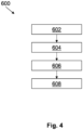
- Fig. 4 shows a flow diagram 600 according to an embodiment.
- the flow diagram 600 depicts a method for handling an electric connection arrangement 101 between a charging post 300 and an electric vehicle 400, as shown, e.g., in Fig. 1 .
- a minimum bending radius of the electric connection arrangement 101 is determined.
- at least one robot arm 520 is arranged at a handle 525 of the electric connection arrangement 101.
- a trajectory 550 of the at least one robot arm 520 is defined. The trajectory 550 stretches between a first resting position 560 and a second charging position 570 of the electric connection arrangement 101.
- the trajectory 550 is designed for moving the electric connection arrangement 101 with a bending radius greater than the minimum bending radius of the electric connection arrangement 101. Considering the minimum bending radius may prevent the electric connection arrangement 101 from breaking.
- the at least one robot arm 520 is handled based on the trajectory 550, particularly before and/or after charging the electric vehicle 400.
Landscapes
- Engineering & Computer Science (AREA)
- Power Engineering (AREA)
- Transportation (AREA)
- Mechanical Engineering (AREA)
- Electric Propulsion And Braking For Vehicles (AREA)
Abstract
The invention relates to the field of electric connection arrangements, particularly for charging electric vehicles (400). The electric connection arrangement (100, 101) may connect a power converter (200) with a charging post (300) and/or the charging post (300) with an electric vehicle (400). The electric connection arrangement (100, 101) comprises a superconducting cable (110) for power transmission; a cooling layer (120), arranged around the superconducting cable (110); and an outer layer (130) configured for isolating the connection arrangement.
Description
- The invention relates to the field of electric connection arrangements, particularly for charging electric vehicles. The invention further relates to a use, to a method, and to a non-transitory computer-readable storage medium.
- At least some types of electric vehicles (EVs) are charged with high currents, i.e. currents of several hundreds of Amps. This may be caused, e.g., by a demand for fast charging the EV, and/or due to big batteries of the EV to be charged, for instance for batteries of a truck. These high currents usually produce a high power loss in the cables that are used for charging, resulting, e.g., in heat problems even for copper cables with low resistance. Therefore, it is desirable to provide means for reducing the power loss in these cables.
- It is an objective of the invention to provide an electric connection arrangement, e.g. a kind of cable, with lower power loss. This objective is achieved by the subject-matter of the independent claims. Further embodiments are evident from the dependent claims and the following description.
- One aspect relates to an electric connection arrangement for connecting a power converter with a charging post and/or for connecting the charging post with an electric vehicle. The electric connection arrangement comprises a superconducting cable for power transmission; a cooling layer, arranged around the superconducting cable; and an outer layer configured for isolating the connection arrangement.
- The electric connection arrangement may be used in several regions of an EV charging system. Examples may comprise one or more sections, e.g. a connection between the power converter and the charging post, a connection between the charging post and an EV, and/or further sections. The connection(s) may comprise one line for each section, or may comprise several sub-sections. The current over the electric connection arrangements may be AC (alternating current) or DC (direct current). The power converter of the EV charging system may, e.g., be connected to a medium voltage (MV) line. The posts may be located on a different site than the power converter, e.g. more than, e.g., 5 metres, 10 metres, 20 metres, 50 metres, of even more than 100 metres away from the power converter. The line between the charging post and the EV may be significantly shorter, e.g. only a couple of metres.
- The connection between the power converter and the charging post may be a connection that is not moved during its regular operation. In some embodiments, this connection may be arranged subterraneously. The connection between the charging post and the EV may be moved during - and/or right before or right after - its regular operation, e.g. when the electric connection arrangement is moved from a resting position of the cable to a charging position, e.g. into a plug of the EV, and/or when it is moved back. Hence, not-moveable sections of the electric connection arrangement may be designed and/or optimized differently than the moveable sections. As an example, the connection between the power converter and the charging post may be optimized for best conduction conditions, whereas the connection between the charging post and the electric vehicle may be a trade-off between best conduction conditions and a minimum of flexibility of the electric connection arrangement.
- The superconducting cable may consist of a high-temperature superconductor. This may advantageously reduce the overall cooling effort. The superconducting cable may comprise one or more wires. The number of wires may influence the design of the cooling layer. Particularly for an electrically non-insulating cooling fluid, the one or more wires may be wrapped by an electrically insulating and thermally well-conducting material. This may be preferred for one-wire arrangements. Cooling fluids used for the cooling layer may comprise Liquid Helium, Liquid Nitrogen, Industrial refrigerants, R-410A, R-134A, R404A, oil, water-glycol, liquid CO2, and others. The cooling fluids that are actually used may depend on the critical temperature of the superconductor. The cooling layer is configured for cooling the superconducting cable to a temperature low enough that the superconducting cable has a superconducting property, i.e. an electrical resistance of zero ohms. A reserve of a few centigrade may be foreseen, i.e. the cooling layer may be configured for providing a lower temperature than required for the superconducting cable. Lorenz forces under normal operation, and especially under short-circuit conditions, may cause forces that push the conductors apart. The magnetic fields are also detrimental to the superconductive properties of the conductor materials. To counteract this force, a certain distance between the conductors may be useful. However, this may will increase the inductance, which could be desirable to minimize. Hence, additionally or as an alternative, a strong sheath or straps may be favoured, compared to a "glue layer".
- The outer layer, which is configured for thermally - and, optionally, electrically - isolating the connection arrangement, may further contribute to keep the temperature of the superconducting cable low enough for the cable's superconducting property. A highly thermally isolating outer layer may, additionally, contribute to keep the temperature low even in cases of temporarily reduced cooling power.
- This electric connection arrangement advantageously provides a solution with zero power loss. This does not only reduce thermal problems caused by the high currents, but also leads to an increased efficiency of the EV charging system. Furthermore, the diameter of the cables can be reduced. Particularly the combination of these materials and/or features enables a new category of power transmission. Hence, the electric connection arrangement may not only be applied to EV charging systems, but also, for instance, to battery storage systems, solar power, power distribution, other applications that require high currents.
- In various embodiments, the electric connection arrangement further comprises an outer mantle for protecting the connection arrangement. The outer mantle may protect particularly the outer layer - but also the cooling layer and/or the superconducting cable - from damaging, e.g. from mechanical damaging and/or from chemical, e.g. caused by dirt and water. The outer mantle may comprise materials like LDPE (Low-Density-Polyethylen), HDPE (High Density Polyethylen), steel armor, PVC (Polyvinyl Chloride), further materials, and/or composites.
- In various embodiments, the cooling layer is configured for keeping a temperature of the superconducting cable at or below -15 °C, -25 °C, -50 °C, -60 °C, -70 °C, -140 °C, -190 °C. The temperature ranges to be achieved may depend on the critical temperature of the superconducting cable. The temperature ranges may further be kept above temperatures of 77 Kelvin, i.e. -196.2 °C or -321.1 °F.
- In various embodiments, the cooling layer comprises materials like liquid helium, liquid nitrogen, industrial refrigerants, R-410A, R-134A, R404A, oil, water-glycol, liquid CO2, and others. The selection of the fluids of the cooling layer may depend on criteria like heat capacity, boiling point, conductivity, polar/non-polar, storage requirements, corrosiveness, and/or further ones.
- In various embodiments, the outer layer comprises aerogels and/or aerogel blankets. Aerogels are advantageously good thermal insulators, so that using the electric connection arrangement becomes feasible in normal ambient temperature ranges, without elaborate and effortful housings. Aerogels are advantageously also good electrical insulators, so that a high degree of safety can be provided, even for high charging voltages.
- In various embodiments, the superconducting cable comprises at least one of MgB2, copper-substituted lead apetite, Cuperates, YBCO, HgBa2Ca2Cu3O8+δ, Indium Tin oxide, higher titanium oxides, NbTi, Nb3Sn, and/or further ones.
- In various embodiments, the superconducting cable has a diameter of about 1 cm, about 5 cm, about 10 cm, about 20 cm, about 50 cm, and/or others. Additionally or as an alternative, the superconducting cable consists of a plurality of wires having a diameter in a range of about 0.1 cm to 1 cm.
- In various embodiments, the electric connection arrangement is configured for currents between 100 A and 7000 A, for example between 300 A and 5000 A, for example between 500 A and 3000 A. The EV charging systems may be designed, for instance, for current ranges of several thousand Amps, voltages up to 1000 V, 1250 V, 1500 V, 1800 V, 3000 V and power ranges up to 30 MWatts.
- The electric connection arrangement described above and/or below may be designed for passenger cars, for trucks, even for high-power trucks like mining trucks, for some types of ships and/or for electrically driven airplanes. Moreover, this electric connection arrangement may also be applied to light rail, heavy rail, aircraft like eVTOL (electric Vertical Take-Off and Landing aircraft), helicopters, tanks, ships, ferries, hovercraft, battery storage, mobile home, trailers, and/or further ones.
- An aspect relates to a use of an electric connection arrangement as described above and/or below for an electric connection between a power converter and a charging post and/or for an electric connection between the charging post and an electric vehicle, and/or for an electric connection between the power converter and an electric grid, e.g. to a medium-voltage (MV) grid.
- An aspect relates to a method for handling an electric connection arrangement between a charging post and an electric vehicle, the method comprising the steps of: determining a minimum bending radius of the electric connection arrangement; arranging at least one robot arm at a handle of the electric connection arrangement; defining a trajectory of the at least one robot arm between a first resting position to a second charging position, the trajectory being designed for moving the electric connection arrangement with a bending radius greater than the minimum bending radius of the electric connection arrangement; and
handling, by a control unit, the at least one robot arm based on the trajectory before and/or after charging the electric vehicle. - The robot arm may comprise one or more joints. The robot arm may be integrated in the electric connection arrangement, and/or may be designed as an exoskeleton. The minimum bending radius of the electric connection arrangement may be 10 cm. This method may contribute to make the use of the this electric connection arrangement feasible. Particularly, the robot-based plugging and unplugging of the connection arrangement may prevent the superconducting cable from breaking, even in cases when quite brittle superconducting cables are used. Hence, one of the main hurdles of using superconductors for moveable cables may, thus, be overcome. Using a plurality of thin wires may further contribute to a smaller minimum bending radius of the electric connection arrangement.
- An aspect relates to a non-transitory computer-readable storage medium having a program stored therein, which, when executed on a control unit instructs at least one robot arm to handle said robot arm based on a defined trajectory.
- For further clarification, the invention is described by means of embodiments shown in the figures. These embodiments are to be considered as examples only, but not as limiting.
- The drawings depict:
- Fig. 1
- schematically a scenario of an EV system according to an embodiment;
- Fig. 2a, 2b
- schematically an example of an electric connection arrangement according to an embodiment;
- Fig. 3
- schematically an example of a robot arm according to an embodiment;
- Fig. 4
- a flow diagram according to an embodiment.
-
Fig. 1 shows schematically a scenario of an EV system according to an embodiment. The EV system comprises apower converter 200, a plurality ofposts 300 and an electric vehicle (EV) 400. Thepower converter 200 may be connected to a power source, e.g. to a medium voltage (MV) grid. Anelectric connection arrangement 100 is arranged between thepower converter 200 and the chargingpost 300. Anelectric connection arrangement 101 is arranged between the chargingpost 300 and theEV 400. The connection(s) 100 and 101 may comprise one line for each section, or they may comprise several sub-sections. In various embodiments, theconnection 100 may be longer thanconnection 101. In some embodiments, theconnection 101 may be arranged subterraneously. - In some embodiments, the
electric connection arrangements electric connection arrangement 100 may be designed differently than thearrangement 101. Particularly, theelectric connection arrangement 101 may have a higher mechanical flexibility, so that thearrangement 101 may be moved between a resting position to a charging position, in which the EV's charging system is plugged to theelectric connection arrangement 101, e.g. via a connector. The handling of thearrangement 101 may, optionally, be supported by arobot arm 520, which may be controlled by acontrol unit 500. -
Figs. 2a and 2b show schematically an example of anelectric connection arrangement 100 and/or 101 according to an embodiment.Figs. 2a and 2b show basically the same entity,Fig. 2a in a perspective view andFig. 2b in a sectional view. Theelectric connection arrangement superconducting cable 110 for power transmission. Thesuperconducting cable 110 may be of a material of high-temperature superconductors. Acooling layer 120 is arranged around thesuperconducting cable 110. In some embodiments, thesuperconducting cable 110 may comprise a plurality of wires, so that the fluid of thecooling layer 120 may flow between the plurality of wires. Theelectric connection arrangement outer layer 130, which configured for isolating, particularly thermally isolating, theconnection arrangement - In various embodiments, the electric connection arrangement may further comprise an
outer mantle 140 for protecting the connection arrangement. The outer mantle may protect particularly the outer layer - but also the cooling layer and/or the superconducting cable - from damaging, e.g. from mechanical damaging and/or from chemical, e.g. caused by dirt and water. -
Fig. 3 shows schematically an example of arobot arm 520, for moving theelectric connection arrangement 101 from afirst resting position 560 to asecond charging position 570 and/or back. Therobot arm 520 may be one piece or comprise a plurality ofsegments robot arm 520 may hold aconnector 525, which is configured plugging into a corresponding electric connection of an EV (not shown). The moving may be done along atrajectory 550 of the at least onerobot arm 520. In cases where a plurality of (e.g. segmented)robot arms 520 are used to support thearrangement 101, a plurality oftrajectories 550 may be followed. The trajectory (or trajectories) 550 may particularly take into consideration that theelectric connection arrangement 101, particularly itssuperconducting cable 110, has a limited flexibility, because at least some superconducting cable materials may be brittle and should be protected from breaking. In other words: When moving theelectric connection arrangement 101, the movement should in no section of theelectric connection arrangement 101 fall below a minimum bending radius. Hence, thetrajectory 550 is designed or defined for moving theelectric connection arrangement 101 with a bending radius greater than the minimum bending radius of theelectric connection arrangement 101. The movement may be performed fully automated or, in some cases, partly supported manually. -
Fig. 4 shows a flow diagram 600 according to an embodiment. The flow diagram 600 depicts a method for handling anelectric connection arrangement 101 between a chargingpost 300 and anelectric vehicle 400, as shown, e.g., inFig. 1 . In astep 602, a minimum bending radius of theelectric connection arrangement 101 is determined. In astep 604, at least onerobot arm 520 is arranged at ahandle 525 of theelectric connection arrangement 101. In astep 606, atrajectory 550 of the at least onerobot arm 520 is defined. Thetrajectory 550 stretches between afirst resting position 560 and asecond charging position 570 of theelectric connection arrangement 101. Thetrajectory 550 is designed for moving theelectric connection arrangement 101 with a bending radius greater than the minimum bending radius of theelectric connection arrangement 101. Considering the minimum bending radius may prevent theelectric connection arrangement 101 from breaking. In astep 608, the at least onerobot arm 520 is handled based on thetrajectory 550, particularly before and/or after charging theelectric vehicle 400. -
- 100, 101
- electric connection arrangement
- 110
- superconducting cable
- 120
- cooling layer
- 130
- outer layer
- 140
- outer mantle
- 200
- power converter
- 300
- charging post
- 400
- electric vehicle (EV)
- 500
- control unit
- 520
- robot arm
- 521 - 523
- segments
- 525
- connector, handle of the electric connection arrangement
- 550
- trajectory
- 560
- resting position
- 570
- charging position
- 600
- flow diagram
- 602 - 608
- steps
Claims (11)
- An electric connection arrangement (100, 101) for connecting a power converter (200) with a charging post (300) and/or for connecting the charging post (300) with an electric vehicle (400), the electric connection arrangement (100, 101) comprising:a superconducting cable (110) for power transmission;a cooling layer (120), arranged around the superconducting cable (110); andan outer layer (130) configured for isolating the connection arrangement.
- The electric connection arrangement (100, 101) of claim 1,
further comprising an outer mantle (140) for protecting the connection arrangement. - The electric connection arrangement (100, 101) of claim 1 or 2,
wherein the cooling layer (120) is configured for keeping a temperature of the superconducting cable (110) at or below -15 °C, -25 °C, -50 °C, -60 °C, -70 °C, -140 °C, -190 °C. - The electric connection arrangement (100, 101) of any one of the preceding claims,
wherein the cooling layer (120) comprises liquid helium, liquid nitrogen, industrial refrigerants, R 410A, R-134A, R404A, oil, water-glycol, liquid CO2, and others. - The electric connection arrangement (100, 101) of any one of the preceding claims,
wherein the outer layer (130) comprises aerogels and/or aerogel blankets. - The electric connection arrangement (100, 101) of any one of the preceding claims,
wherein the superconducting cable (110) comprises at least one of MgB2, copper-substituted lead apetite, Cuperates, YBCO, HgBa2Ca2Cu3O8+δ, Indium Tin oxide, higher titanium oxides, NbTi, Nb3Sn, and/or further ones. - The electric connection arrangement (100, 101) of any one of the preceding claims,
wherein the electric connection arrangement (100, 101) is configured for currents between 100 A and 5000 A, for example between 300 A and 4000 A, for example between 500 A and 3000 A. - The electric connection arrangement (100, 101) of any one of the preceding claims,
wherein the electric vehicle (400) is a passenger car, a truck, a ship and/or an aircraft. - Use of an electric connection arrangement (100, 101) of any one of the preceding claims for an electric connection between a power converter (200) and a charging post (300) and/or for an electric connection between the charging post (300) and an electric vehicle (400), and/or for an electric connection between the power converter (200) and an electric grid.
- A method for handling an electric connection arrangement (101) between a charging post (300) and an electric vehicle (400), the method comprising the steps of:determining a minimum bending radius of the electric connection arrangement (101);arranging at least one robot arm (520) at a handle (525) of the electric connection arrangement (101);defining a trajectory (550) of the at least one robot arm (520) between a first resting position (560) to a second charging position (570), the trajectory (550) being designed for moving the electric connection arrangement (101) with a bending radius greater than the minimum bending radius of the electric connection arrangement (101); andhandling, by a control unit (500), the at least one robot arm (520) based on the trajectory (550) before and/or after charging the electric vehicle (400).
- A non-transitory computer-readable storage medium having a program stored therein, which, when executed on a control unit (500) instructs at least one robot arm (520) to handle said robot arm (520) based on a trajectory (550) defined according to claim 10.
Priority Applications (1)
| Application Number | Priority Date | Filing Date | Title |
|---|---|---|---|
| EP23191146.2A EP4506205A1 (en) | 2023-08-11 | 2023-08-11 | Superconductors for ev chargers |
Applications Claiming Priority (1)
| Application Number | Priority Date | Filing Date | Title |
|---|---|---|---|
| EP23191146.2A EP4506205A1 (en) | 2023-08-11 | 2023-08-11 | Superconductors for ev chargers |
Publications (1)
| Publication Number | Publication Date |
|---|---|
| EP4506205A1 true EP4506205A1 (en) | 2025-02-12 |
Family
ID=87571357
Family Applications (1)
| Application Number | Title | Priority Date | Filing Date |
|---|---|---|---|
| EP23191146.2A Withdrawn EP4506205A1 (en) | 2023-08-11 | 2023-08-11 | Superconductors for ev chargers |
Country Status (1)
| Country | Link |
|---|---|
| EP (1) | EP4506205A1 (en) |
Citations (3)
| Publication number | Priority date | Publication date | Assignee | Title |
|---|---|---|---|---|
| US20220258626A1 (en) * | 2021-02-17 | 2022-08-18 | Mikko Kalervo Vaananen | Method and means for electric vehicle battery charging |
| US20230089259A1 (en) * | 2020-12-18 | 2023-03-23 | The Boeing Company | Fast Battery Charging Method and System for Large Power Load Applications |
| KR20230077378A (en) * | 2021-11-25 | 2023-06-01 | 르노코리아자동차 주식회사 | The eletric vehicle charging method using superconductiong wires or copper wires by an eletric vehicle inlet cable |
-
2023
- 2023-08-11 EP EP23191146.2A patent/EP4506205A1/en not_active Withdrawn
Patent Citations (3)
| Publication number | Priority date | Publication date | Assignee | Title |
|---|---|---|---|---|
| US20230089259A1 (en) * | 2020-12-18 | 2023-03-23 | The Boeing Company | Fast Battery Charging Method and System for Large Power Load Applications |
| US20220258626A1 (en) * | 2021-02-17 | 2022-08-18 | Mikko Kalervo Vaananen | Method and means for electric vehicle battery charging |
| KR20230077378A (en) * | 2021-11-25 | 2023-06-01 | 르노코리아자동차 주식회사 | The eletric vehicle charging method using superconductiong wires or copper wires by an eletric vehicle inlet cable |
Similar Documents
| Publication | Publication Date | Title |
|---|---|---|
| AU2009298856B2 (en) | Electricity transmission cooling system | |
| US10128026B2 (en) | Superconducting wire | |
| EP4004953B1 (en) | Heavy-current charging cable for charging an electric vehicle | |
| EP1151442B1 (en) | Electrical power transmission system using superconductors | |
| NL2023045A (en) | Cable assembly | |
| US9959955B2 (en) | Superconducting cable | |
| KR20110102514A (en) | Fault current limiting HTS cable and its formation method | |
| KR20090115751A (en) | HTS Wire | |
| AU737317B2 (en) | Magnetic energy storage | |
| US7743485B1 (en) | Method of manufacturing a superconducting cable | |
| EP1034581B1 (en) | A power induction device | |
| US12334233B2 (en) | Cooled charging cable | |
| Bruzek et al. | MgB 2-based MVDC superconducting power cable in liquid hydrogen for hybrid energy distribution | |
| JP2001525609A (en) | High voltage induction device | |
| US20190066878A1 (en) | Energy Transmission Apparatus For A Vehicle | |
| US8332005B2 (en) | Superconducting electrical cable | |
| WO2006085409A1 (en) | Intermediate joint structure of superconductive cable | |
| CN114220601B (en) | High-reliability superconducting cable structure | |
| EP4210175A1 (en) | Charging cable, charging interface and method for charging electric cars | |
| JP5910996B2 (en) | Superconducting cable and method of manufacturing superconducting cable | |
| Cheetham et al. | Design of Warm Dielectric Terminations and Nodes for High Temperature Superconducting Power Cables | |
| Morandi et al. | Feasibility of high voltage DC superconducting cables with extruded warm dielectric | |
| CN211239262U (en) | Ice melting device for transmission conductor | |
| US20250222801A1 (en) | Lower loss charging cable | |
| CN107610835A (en) | Superconducting energy pipeline protected by LNG cooling CF4 |
Legal Events
| Date | Code | Title | Description |
|---|---|---|---|
| PUAI | Public reference made under article 153(3) epc to a published international application that has entered the european phase |
Free format text: ORIGINAL CODE: 0009012 |
|
| STAA | Information on the status of an ep patent application or granted ep patent |
Free format text: STATUS: THE APPLICATION HAS BEEN PUBLISHED |
|
| AK | Designated contracting states |
Kind code of ref document: A1 Designated state(s): AL AT BE BG CH CY CZ DE DK EE ES FI FR GB GR HR HU IE IS IT LI LT LU LV MC ME MK MT NL NO PL PT RO RS SE SI SK SM TR |
|
| STAA | Information on the status of an ep patent application or granted ep patent |
Free format text: STATUS: THE APPLICATION IS DEEMED TO BE WITHDRAWN |
|
| 18D | Application deemed to be withdrawn |
Effective date: 20250813 |