EP4506196A1 - Vehicle driving device - Google Patents
Vehicle driving device Download PDFInfo
- Publication number
- EP4506196A1 EP4506196A1 EP24188241.4A EP24188241A EP4506196A1 EP 4506196 A1 EP4506196 A1 EP 4506196A1 EP 24188241 A EP24188241 A EP 24188241A EP 4506196 A1 EP4506196 A1 EP 4506196A1
- Authority
- EP
- European Patent Office
- Prior art keywords
- vehicle
- case portion
- electrical machine
- rotating electrical
- driving device
- Prior art date
- Legal status (The legal status is an assumption and is not a legal conclusion. Google has not performed a legal analysis and makes no representation as to the accuracy of the status listed.)
- Granted
Links
Images


Classifications
-
- B—PERFORMING OPERATIONS; TRANSPORTING
- B60—VEHICLES IN GENERAL
- B60K—ARRANGEMENT OR MOUNTING OF PROPULSION UNITS OR OF TRANSMISSIONS IN VEHICLES; ARRANGEMENT OR MOUNTING OF PLURAL DIVERSE PRIME-MOVERS IN VEHICLES; AUXILIARY DRIVES FOR VEHICLES; INSTRUMENTATION OR DASHBOARDS FOR VEHICLES; ARRANGEMENTS IN CONNECTION WITH COOLING, AIR INTAKE, GAS EXHAUST OR FUEL SUPPLY OF PROPULSION UNITS IN VEHICLES
- B60K1/00—Arrangement or mounting of electrical propulsion units
-
- B—PERFORMING OPERATIONS; TRANSPORTING
- B60—VEHICLES IN GENERAL
- B60K—ARRANGEMENT OR MOUNTING OF PROPULSION UNITS OR OF TRANSMISSIONS IN VEHICLES; ARRANGEMENT OR MOUNTING OF PLURAL DIVERSE PRIME-MOVERS IN VEHICLES; AUXILIARY DRIVES FOR VEHICLES; INSTRUMENTATION OR DASHBOARDS FOR VEHICLES; ARRANGEMENTS IN CONNECTION WITH COOLING, AIR INTAKE, GAS EXHAUST OR FUEL SUPPLY OF PROPULSION UNITS IN VEHICLES
- B60K7/00—Disposition of motor in, or adjacent to, traction wheel
- B60K7/0007—Disposition of motor in, or adjacent to, traction wheel the motor being electric
-
- B—PERFORMING OPERATIONS; TRANSPORTING
- B60—VEHICLES IN GENERAL
- B60K—ARRANGEMENT OR MOUNTING OF PROPULSION UNITS OR OF TRANSMISSIONS IN VEHICLES; ARRANGEMENT OR MOUNTING OF PLURAL DIVERSE PRIME-MOVERS IN VEHICLES; AUXILIARY DRIVES FOR VEHICLES; INSTRUMENTATION OR DASHBOARDS FOR VEHICLES; ARRANGEMENTS IN CONNECTION WITH COOLING, AIR INTAKE, GAS EXHAUST OR FUEL SUPPLY OF PROPULSION UNITS IN VEHICLES
- B60K11/00—Arrangement in connection with cooling of propulsion units
- B60K11/02—Arrangement in connection with cooling of propulsion units with liquid cooling
-
- B—PERFORMING OPERATIONS; TRANSPORTING
- B60—VEHICLES IN GENERAL
- B60K—ARRANGEMENT OR MOUNTING OF PROPULSION UNITS OR OF TRANSMISSIONS IN VEHICLES; ARRANGEMENT OR MOUNTING OF PLURAL DIVERSE PRIME-MOVERS IN VEHICLES; AUXILIARY DRIVES FOR VEHICLES; INSTRUMENTATION OR DASHBOARDS FOR VEHICLES; ARRANGEMENTS IN CONNECTION WITH COOLING, AIR INTAKE, GAS EXHAUST OR FUEL SUPPLY OF PROPULSION UNITS IN VEHICLES
- B60K17/00—Arrangement or mounting of transmissions in vehicles
- B60K17/04—Arrangement or mounting of transmissions in vehicles characterised by arrangement, location or kind of gearing
- B60K17/043—Transmission unit disposed in on near the vehicle wheel, or between the differential gear unit and the wheel
- B60K17/046—Transmission unit disposed in on near the vehicle wheel, or between the differential gear unit and the wheel with planetary gearing having orbital motion
-
- B—PERFORMING OPERATIONS; TRANSPORTING
- B60—VEHICLES IN GENERAL
- B60L—PROPULSION OF ELECTRICALLY-PROPELLED VEHICLES; SUPPLYING ELECTRIC POWER FOR AUXILIARY EQUIPMENT OF ELECTRICALLY-PROPELLED VEHICLES; ELECTRODYNAMIC BRAKE SYSTEMS FOR VEHICLES IN GENERAL; MAGNETIC SUSPENSION OR LEVITATION FOR VEHICLES; MONITORING OPERATING VARIABLES OF ELECTRICALLY-PROPELLED VEHICLES; ELECTRIC SAFETY DEVICES FOR ELECTRICALLY-PROPELLED VEHICLES
- B60L15/00—Methods, circuits, or devices for controlling the traction-motor speed of electrically-propelled vehicles
-
- B—PERFORMING OPERATIONS; TRANSPORTING
- B60—VEHICLES IN GENERAL
- B60L—PROPULSION OF ELECTRICALLY-PROPELLED VEHICLES; SUPPLYING ELECTRIC POWER FOR AUXILIARY EQUIPMENT OF ELECTRICALLY-PROPELLED VEHICLES; ELECTRODYNAMIC BRAKE SYSTEMS FOR VEHICLES IN GENERAL; MAGNETIC SUSPENSION OR LEVITATION FOR VEHICLES; MONITORING OPERATING VARIABLES OF ELECTRICALLY-PROPELLED VEHICLES; ELECTRIC SAFETY DEVICES FOR ELECTRICALLY-PROPELLED VEHICLES
- B60L50/00—Electric propulsion with power supplied within the vehicle
- B60L50/50—Electric propulsion with power supplied within the vehicle using propulsion power supplied by batteries or fuel cells
- B60L50/60—Electric propulsion with power supplied within the vehicle using propulsion power supplied by batteries or fuel cells using power supplied by batteries
-
- B—PERFORMING OPERATIONS; TRANSPORTING
- B60—VEHICLES IN GENERAL
- B60L—PROPULSION OF ELECTRICALLY-PROPELLED VEHICLES; SUPPLYING ELECTRIC POWER FOR AUXILIARY EQUIPMENT OF ELECTRICALLY-PROPELLED VEHICLES; ELECTRODYNAMIC BRAKE SYSTEMS FOR VEHICLES IN GENERAL; MAGNETIC SUSPENSION OR LEVITATION FOR VEHICLES; MONITORING OPERATING VARIABLES OF ELECTRICALLY-PROPELLED VEHICLES; ELECTRIC SAFETY DEVICES FOR ELECTRICALLY-PROPELLED VEHICLES
- B60L58/00—Methods or circuit arrangements for monitoring or controlling batteries or fuel cells, specially adapted for electric vehicles
- B60L58/10—Methods or circuit arrangements for monitoring or controlling batteries or fuel cells, specially adapted for electric vehicles for monitoring or controlling batteries
- B60L58/24—Methods or circuit arrangements for monitoring or controlling batteries or fuel cells, specially adapted for electric vehicles for monitoring or controlling batteries for controlling the temperature of batteries
- B60L58/26—Methods or circuit arrangements for monitoring or controlling batteries or fuel cells, specially adapted for electric vehicles for monitoring or controlling batteries for controlling the temperature of batteries by cooling
-
- B—PERFORMING OPERATIONS; TRANSPORTING
- B60—VEHICLES IN GENERAL
- B60K—ARRANGEMENT OR MOUNTING OF PROPULSION UNITS OR OF TRANSMISSIONS IN VEHICLES; ARRANGEMENT OR MOUNTING OF PLURAL DIVERSE PRIME-MOVERS IN VEHICLES; AUXILIARY DRIVES FOR VEHICLES; INSTRUMENTATION OR DASHBOARDS FOR VEHICLES; ARRANGEMENTS IN CONNECTION WITH COOLING, AIR INTAKE, GAS EXHAUST OR FUEL SUPPLY OF PROPULSION UNITS IN VEHICLES
- B60K1/00—Arrangement or mounting of electrical propulsion units
- B60K2001/001—Arrangement or mounting of electrical propulsion units one motor mounted on a propulsion axle for rotating right and left wheels of this axle
-
- B—PERFORMING OPERATIONS; TRANSPORTING
- B60—VEHICLES IN GENERAL
- B60K—ARRANGEMENT OR MOUNTING OF PROPULSION UNITS OR OF TRANSMISSIONS IN VEHICLES; ARRANGEMENT OR MOUNTING OF PLURAL DIVERSE PRIME-MOVERS IN VEHICLES; AUXILIARY DRIVES FOR VEHICLES; INSTRUMENTATION OR DASHBOARDS FOR VEHICLES; ARRANGEMENTS IN CONNECTION WITH COOLING, AIR INTAKE, GAS EXHAUST OR FUEL SUPPLY OF PROPULSION UNITS IN VEHICLES
- B60K7/00—Disposition of motor in, or adjacent to, traction wheel
- B60K2007/0092—Disposition of motor in, or adjacent to, traction wheel the motor axle being coaxial to the wheel axle
-
- B—PERFORMING OPERATIONS; TRANSPORTING
- B60—VEHICLES IN GENERAL
- B60Y—INDEXING SCHEME RELATING TO ASPECTS CROSS-CUTTING VEHICLE TECHNOLOGY
- B60Y2400/00—Special features of vehicle units
- B60Y2400/61—Arrangements of controllers for electric machines, e.g. inverters
-
- B—PERFORMING OPERATIONS; TRANSPORTING
- B60—VEHICLES IN GENERAL
- B60Y—INDEXING SCHEME RELATING TO ASPECTS CROSS-CUTTING VEHICLE TECHNOLOGY
- B60Y2400/00—Special features of vehicle units
- B60Y2400/70—Gearings
- B60Y2400/73—Planetary gearings
-
- B—PERFORMING OPERATIONS; TRANSPORTING
- B60—VEHICLES IN GENERAL
- B60Y—INDEXING SCHEME RELATING TO ASPECTS CROSS-CUTTING VEHICLE TECHNOLOGY
- B60Y2410/00—Constructional features of vehicle sub-units
- B60Y2410/10—Housings
Definitions
- This disclosure relates to a vehicle driving device including a rotating electrical machine.
- a vehicle driving device including a rotating electrical machine is known.
- CN 106183763A (Reference 1) discloses a vehicle driving device including a rotating electrical machine (11), a power transmission mechanism (15), and a pair of mount brackets (2, 8) coupled to a vehicle body.
- One (2) of the pair of mount brackets is fixed to a cover of the rotating electrical machine (11), and the other (8) of the pair of mount brackets is fixed to a left side case of the power transmission mechanism (15).
- the mount bracket may be increased in size to ensure a strength necessary to reduce shaking of the vehicle driving device.
- a vehicle driving device includes: a rotating electrical machine; an output member configured to be drivingly coupled to a wheel; a power transmission mechanism configured to transmit a driving force between the rotating electrical machine and the output member; an inverter module configured to drive and control the rotating electrical machine; a power source module including at least one of a voltage conversion circuit electrically connected to an on-vehicle battery and configured to perform voltage conversion of the on-vehicle battery, a charging circuit configured to charge the on-vehicle battery from an external power source, and a power supply circuit configured to supply power from the on-vehicle battery to an outside; a first case portion in which the rotating electrical machine and the power transmission mechanism are accommodated; a second case portion in which at least one of the inverter module and the power source module are accommodated; and a mount bracket configured to be coupled to a vehicle body of a vehicle in an on-vehicle state that is a state of being mounted on the vehicle, in which in the on-vehicle state,
- the mount bracket since the mount bracket is attached to the second case portion disposed on the upper side with respect to the first case portion in the on-vehicle state, the dimension of the mount bracket in the up-down direction is easily reduced even when the coupling portion of the mount bracket and the vehicle body is located on the upper side with respect to the rotating electrical machine and the power transmission mechanism. Therefore, it is easy to reduce the size and weight of the mount bracket while ensuring the strength of the mount bracket.
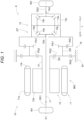
- Fig. 1 is a diagram illustrating a vehicle 8 equipped with the vehicle driving device 10.
- the vehicle driving device 10 includes a rotating electrical machine MG, an output member drivingly coupled to wheels (W1, W2), and a power transmission mechanism GT that transmits a driving force between the rotating electrical machine MG and the output member.
- a direction along a rotation axis center X1 of a rotor 12 of the rotating electrical machine MG is referred to as an axial direction L.
- the power transmission mechanism GT is disposed on an axial direction first side L1 that is one side in the axial direction L with respect to the rotor 12 of the rotating electrical machine MG.
- the rotating electrical machine MG is a driving force source of the vehicle 8.
- the power transmission mechanism GT includes a speed reducer 16 and a differential gear mechanism 15.
- Examples of the "output member" include a first side gear 15a, a second side gear 15b, spline engagement portions 15d, a first drive shaft DS1, a second drive shaft DS2, and a coupling shaft 17 to be described later.
- the vehicle driving device 10 includes a case 20, and the case 20 supports an inverter module INV and a power source module PWR to be described later.
- the case 20 further supports a refrigerant circuit module 46 to be described later.
- the term "support” is not limited to the case of using an external portion of the case 20, but also includes an aspect of being supported on an inner surface of the case 20. That is, the inverter module INV, the power source module PWR, and the refrigerant circuit module 46 may be accommodated in the case 20.
- the inverter module INV and the power source module PWR may be accommodated in the case 20, and the refrigerant circuit module 46 may be supported outside the case 20.
- the term “drivingly coupled” refers to a state in which two rotating components are coupled such that a driving force can be transmitted, and includes a state in which the two rotating components are coupled to rotate integrally or a state in which the two rotating components are coupled such that a driving force can be transmitted via one or two or more transmission members.
- a transmission member include various members that transmit the rotation at the same speed or variable speeds, such as shafts, gear mechanisms, belts, and chains.
- the transmission member may include an engagement device that selectively transmits the rotation and the driving force, such as a friction engagement device and a meshing type engagement device.
- the term “drivingly coupled” refers to a state in which the planetary gear mechanism is drivingly coupled without another rotating component.
- the term “rotate integrally” refers to integrally rotating whether separable or non-separable. That is, a plurality of members that integrally rotate may be integrally formed from the same member, or may be implemented by separate members and integrated by welding, spline connection, or the like.
- overlapping in a specific direction view relating to an arrangement of two elements means that when a virtual straight line parallel to a visual line direction is moved in directions each orthogonal to the virtual straight line, there is at least a part of a region in which the virtual straight line intersects with both of the two elements.
- the output member is drivingly coupled to a pair of wheels (W1, W2).
- the pair of wheels includes a first wheel W1 and a second wheel W2, the first wheel W1 is drivingly coupled to the first drive shaft DS1, and the second wheel W2 is drivingly coupled to the second drive shaft DS2.
- a pair of side gears (15a, 15b), which are output gears of the differential gear mechanism 15, include the first side gear 15a and the second side gear 15b.
- the first side gear 15a is drivingly coupled to the first drive shaft DS1 via the coupling shaft 17, and the second side gear 15b is drivingly coupled to the second drive shaft DS2.
- first side gear 15a and the coupling shaft 17 are coupled by spline connection
- second side gear 15b and the second drive shaft DS2 are also coupled by spline connection
- Coupling portions thereof are the spline engagement portions 15d.
- the direction along the rotation axis center X1 of the rotor 12 is referred to as the "axial direction L" as described above. Further, one side in the axial direction L is referred to as the "axial direction first side L1", and the other side in the axial direction L is referred to as an "axial direction second side L2".
- the rotating electrical machine MG, the speed reducer 16, and the differential gear mechanism 15 are disposed coaxially in this order from the axial direction second side L2 toward the axial direction first side L1.
- the vehicle driving device 10 of the present embodiment has a single-shaft configuration.
- a shaft on which the rotating electrical machine MG, the speed reducer 16, and the differential gear mechanism 15 having the rotation axis center X1 as a shaft center are disposed is a rotation shaft of the vehicle driving device 10, and is a rotation shaft of the rotating electrical machine MG, the speed reducer 16, and the differential gear mechanism 15.
- a direction orthogonal to the rotation axis center X1 of the rotor 12 is referred to as a "radial direction".
- a side of the rotation axis center X1 of the rotor 12 is referred to as a "radial direction inner side", and an opposite side thereof is referred to as a "radial direction outer side".
- a direction along a vertical direction in a vehicle mounted state in which the vehicle driving device 10 is mounted on the vehicle 8 is referred to as an "up-down direction Z"
- an upper side is referred to as an “upper side Z1 in the up-down direction Z”
- a lower side is referred to as a “lower side Z2 in the up-down direction Z”.
- a direction orthogonal to the axial direction L and the up-down direction Z is referred to as a "front-rear direction H", one side in the front-rear direction H is referred to as a "front-rear direction first side H1", and the other side is referred to as a "front-rear direction second side H2".
- the front-rear direction first side H 1 is a front side of the vehicle 8
- the front-rear direction second side H2 is a rear side.
- a direction orthogonal to the front-rear direction H of a vehicle body 80 as viewed in the up-down direction is referred to as a width direction.
- the "width direction” and the axial direction L of the vehicle 8 are parallel to each other, and may not be parallel to each other.
- the rotating electrical machine MG functions as a driving force source for the wheels (W1, W2).
- the rotating electrical machine MG includes a stator 11 and the rotor 12 coupled to a rotor shaft 13 to rotate integrally with the rotor shaft 13.
- the rotating electrical machine MG is an inner rotor type rotating electrical machine.
- the rotating electrical machine MG includes the rotor 12 rotatably disposed toward the radial direction inner side with respect to the stator 11.
- the rotor 12 includes a rotor core 12a and a permanent magnet (not illustrated) fixed to the rotor core 12a.
- the rotor shaft 13 is formed in a cylindrical shape coaxial with the rotor core 12a, and a sun gear SG of the planetary gear mechanism constituting the speed reducer 16 is disposed on an outer peripheral side of the rotor shaft 13 on the axial direction first side L1 to rotate integrally with the rotor shaft 13.
- the sun gear SG is an input element of the speed reducer 16.
- the rotating electrical machine MG is a rotating field type rotating electrical machine.
- the stator 11 includes a cylindrical stator core 11a and a coil wound around the stator core 11a.
- the coil includes a coil end portion 11b protruding outward in the axial direction L from the stator core 11a.
- a shaft center of the stator core 11a is the same shaft center as the rotation axis center X1 of the rotor 12.
- the shaft center of the stator core 11a is the same shaft center as the rotation axis center X1 of a differential case 15c to be described later.
- the stator 11 is fixed to the case 20.
- the speed reducer 16 includes the input element that rotates integrally with the rotor shaft 13, a fixed element that is fixed to the case 20, an output element that rotates integrally with a differential input element (differential case 15c), and the planetary gear mechanism that includes the planetary gear.
- the planetary gear mechanism is a composite planetary gear mechanism including one sun gearSG, two ring gears (first ring gear RG1 and second ring gear RG2), two planetary gears (first planetary gear PG1 and second planetary gear PG2) that integrally rotate, and a carrier CR that rotatably supports the two planetary gears.
- the first planetary gear PG1 is formed to have a diameter smaller than that of the second planetary gear PG2.
- the sun gear SG rotates integrally with the rotor 12 and the rotor shaft 13.
- the second ring gear RG2 is fixed to the case 20.
- the first ring gear RG1 is disposed on the axial direction first side L1 with respect to the second ring gear RG2 and is coupled to the differential case 15c to rotate integrally with the differential case 15c.
- the second planetary gear PG2 meshes with the sun gear SG and the second ring gear RG2, and the first planetary gear PG1 rotates integrally with the second planetary gear PG2 and meshes with the first ring gear RG1.
- the sun gear SG is the input element
- the second ring gear RG2 is the fixed element
- the first ring gear RG1 is the output element.
- the carrier CR is not coupled to any rotating component or fixed element.
- the differential gear mechanism 15 is a bevel gear type differential gear mechanism and includes pinions 15p and side gears (15a, 15b) which are bevel gears.
- the pinion 15p is supported by the differential case 15c and is rotatably supported by a pinion shaft 15s extending along the radial direction.
- the pinion shaft 15s rotates integrally with the differential case 15c, and the pinion 15p can rotate (spin) around the pinion shaft 15s and can rotate (revolve) around the rotation axis center X1 of the differential case 15c.
- a plurality of pinion shafts 15s are arranged in a radial shape (for example, a cross shape) around the rotation axis center X1 of the differential case 15c, and the pinions 15p are attached to the plurality of pinion shafts 15s, respectively.
- the differential case 15c accommodates the pinions 15p, the side gears (15a, 15b), and the pinion shafts 15s therein.
- the side gears (15a, 15b) include the first side gear 15a and the second side gear 15b and are arranged in a pair spaced apart from each other in the axial direction L.
- the first side gear 15a and the second side gear 15b mesh with the plurality of pinions 15p, respectively, and are arranged to rotate around the rotation axis center X1 of the differential case 15c.
- the first side gear 15a is coupled to the coupling shaft 17 which extends along the axial direction L through the speed reducer 16 and the radial direction inner side of the hollow cylindrical rotor shaft 13.
- the coupling shaft 17 is coupled to the first drive shaft DS1, which is drivingly coupled to the first wheel W1 which is a wheel on the axial direction second side L2, to rotate integrally with the first drive shaft DS1. Therefore, the first side gear 15a is drivingly coupled to the first wheel W1 via the coupling shaft 17.
- the second side gear 15b is coupled to the second drive shaft DS2, which is drivingly coupled to the second wheel W2 which is a wheel on the axial direction first side L1, to rotate integrally with the second drive shaft DS2.
- the first drive shaft DS1, the second drive shaft DS2, the coupling shaft 17, the first side gear 15a, and the second side gear 15b that are drivingly coupled to the wheels (W1, W2) and rotate integrally with the wheels can all be referred to as rotary members corresponding to the output member.
- the first side gear 15a and the second side gear 15b form the differential gear mechanism 15 and may be referred to as the output members.
- Each of the first side gear 15a and the second side gear 15b includes a gear portion that meshes with the pinion 15p and a spline engagement portion 15d coupled to the coupling shaft 17 or the second drive shaft DS2.
- the gear portion corresponds to the rotary member included in the differential gear mechanism
- the spline engagement portion 15d corresponds to the output member.
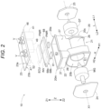
- Fig. 2 is a schematic exploded perspective view of the vehicle driving device 10.
- the vehicle driving device 10 includes the "inverter module INV" for driving and controlling the rotating electrical machine MG.
- the inverter module INV is a circuit module that drives and controls the rotating electrical machine MG.
- the vehicle driving device 10 includes a first case portion 21 in which the rotating electrical machine MG and the power transmission mechanism GT are accommodated.
- the first case portion 21 includes a first side wall portion 26 extending in the up-down direction Z and surrounding a first accommodation chamber E1 in which the rotating electrical machine MG and the power transmission mechanism GT are accommodated as viewed in the up-down direction in an on-vehicle state.
- the vehicle driving device 10 includes a second case portion 22 in which at least one of the inverter module INV and the power source module PWR (to be described later) is accommodated.
- the second case portion 22 includes a second side wall portion 27 extending in the up-down direction Z and surrounding a second accommodation chamber E2 in which at least one of the inverter module INV and the power source module PWR is accommodated when viewed in the up-down direction in the on-vehicle state.
- the second case portion 22 is disposed on the upper side Z1 with respect to the first case portion 21 in the on-vehicle state.
- the second case portion 22 includes a first opening portion 20a of the second accommodation chamber E2 opened toward the upper side Z1.
- the second case portion 22 further includes a first cover portion 23 that covers the first opening portion 20a.
- the inverter module INV and the power source module PWR are accommodated in the second accommodation chamber E2.
- the case 20 is integrally formed to include the first accommodation chamber E1, the second accommodation chamber E2, and a partition wall 28 that partitions the first accommodation chamber E1 and the second accommodation chamber E2. That is, in the present embodiment, an aspect is described in which the first case portion 21, the second case portion 22, and the partition wall 28 are integrally formed by the same member. However, a structure of the case 20 is not limited thereto. For example, an aspect may be used in which the first case portion 21 and the second case portion 22 are integrally formed with the case 20 not including the partition wall 28.
- first case portion 21 and the second case portion 22 are formed by separate members and integrated by a fastening member such as a bolt, welding, or the like with the case 20 not including the partition wall 28.
- a fastening member such as a bolt, welding, or the like
- the first case portion 21 and the second case portion 22 are formed by separate members, a wall of at least one of the members is present at a boundary between the first case portion 21 and the second case portion 22.
- the case 20 is integrated by combining separate members, one or both of the walls in the boundary may be considered as the partition wall 28.
- the first case portion 21 is formed in a cylindrical shape with both sides in the axial direction L opened and includes the cylindrical first side wall portion 26.
- the first side wall portion 26 surrounds the power transmission mechanism GT from the radial direction outer side and corresponds to a portion surrounding the first accommodation chamber E1 of the case 20.
- An opening portion formed on the axial direction second side L2 is a second opening portion 20b, and an opening portion formed on the axial direction first side L1 is a third opening portion 20c.
- the second opening portion 20b is closed by a second cover portion 24, and the third opening portion 20c is closed by a third cover portion 25.
- the second cover portion 24 and the third cover portion 25 are formed with through holes through which the drive shafts (first drive shaft DS1, second drive shaft DS2) pass, respectively.
- the first accommodation chamber E1 and the second accommodation chamber E2 are arranged to be aligned in the up-down direction Z.
- the inverter module INV is disposed on the upper side Z1 with respect to the rotating electrical machine MG and at a position overlapping the rotating electrical machine MG as viewed in the up-down direction along the up-down direction Z.
- the power source module PWR (to be described later) is disposed adjacent to the inverter module INV on the axial direction first side L1. As illustrated in Fig. 2 , the power source module PWR is disposed on the upper side Z1 with respect to the power transmission mechanism GT and at a position overlapping the power transmission mechanism GT when viewed in the up-down direction along the up-down direction Z.
- the case 20 includes a case main body 20m that is an accommodation member serving as a core of the first accommodation chamber E1 and the second accommodation chamber E2.
- the case main body 20m includes the first case portion 21 and the second case portion 22.
- the case main body 20m includes the partition wall 28 that partitions the first accommodation chamber E1 and the second accommodation chamber E2.
- the second accommodation chamber E2 is disposed at a position overlapping the rotating electrical machine MG and the power transmission mechanism GT accommodated in the first case portion 21 as viewed in the up-down direction in the on-vehicle state.
- Fig. 3 is an exploded perspective view illustrating an example of the vehicle driving device 10.
- Fig. 4 is an exploded perspective view of the vehicle driving device 10 of Fig. 3 as viewed from another direction.
- Fig. 5 is a perspective view illustrating an example of the vehicle driving device 10.
- Fig. 6 is a perspective view of the vehicle driving device 10 of Fig. 5 as viewed from another direction.
- Fig. 7 is an enlarged perspective view of the first case portion 21 as viewed from the lower side Z2 and is a perspective view illustrating an auxiliary mount bracket 74.
- the vehicle driving device 10 includes mount members 70 coupled to the vehicle body 80 in the on-vehicle state.
- the mount member 70 includes a mount bush 71 and a mount bracket 72 to be described later.
- a boss portion 27b is provided on each of a pair of outer surfaces facing opposite sides with the second accommodation chamber E2 sandwiched therebetween in the second side wall portion 27.
- the mount bracket 72 is attached to each of the pair of boss portions 27b.
- the mount bracket 72 is fastened to the boss portion 27b by bolts.
- the vehicle driving device 10 includes an auxiliary mount member 75 to be described later.
- the auxiliary mount member 75 includes an auxiliary mount bush 73 and the auxiliary mount bracket 74 to be described later.
- Fig. 8 is a control block diagram of the vehicle driving device 10.
- the vehicle driving device 10 includes the "power source module PWR".
- the power source module PWR includes a voltage conversion circuit (converter 31) that is electrically connected to an on-vehicle battery B2 and performs voltage conversion of the on-vehicle battery B2, and at least one of a charging circuit (charging power supply circuit 32) that is electrically connected to the on-vehicle battery B2 and charges the on-vehicle battery B2 from an external power source 30 and a power supply circuit (charging power supply circuit 32) that is electrically connected to the on-vehicle battery B2 and supplies power from the on-vehicle battery B2 to an outside.
- a voltage conversion circuit converter 31
- a charging circuit charging power supply circuit 32
- a power supply circuit charging power supply circuit 32
- the charging power supply circuit 32 having a bidirectional function of charging the on-vehicle battery B2 and supplying the power from the on-vehicle battery B2 is provided. That is, the charging power supply circuit 32 has functions of a "charging circuit” and a "power supply circuit".
- a high-voltage circuit unit including the inverter module INV and the power source module PWR is formed.
- the rotating electrical machine MG is electrically connected, via an inverter circuit 36, to the on-vehicle battery B2 which is a DC power supply implemented by a power storage device such as a secondary battery or a capacitor.
- the rotating electrical machine MG has a function as a motor (electric motor) that receives electric power supplied from the on-vehicle battery B2 and generates power and a function as a generator (electric generator) that receives power supplied from the wheels (W1, W2) and generates electric power.
- the rotating electrical machine MG generates the driving force by running with the electric power stored in the on-vehicle battery B2 and generates the electric power by the driving force transmitted from a side of the pair of wheels (W1, W2) to charge the on-vehicle battery B2.
- the on-vehicle battery B2 is a high-voltage DC power supply having a rated voltage of about 48 volts to 400 volts. Since the on-vehicle battery B2 supplies the electric power to the rotating electrical machine MG serving as the driving force source of the wheels, the electric power capacity is large, and the physical size is large.
- the on-vehicle battery B2 is disposed under a floor of a cabin 95 (see Fig. 11 ) of the vehicle 8 to ensure a space of the cabin 95 and the like.
- the on-vehicle battery B2 is not only charged by the electric power generated by the rotating electrical machine MG, but also can be charged by the electric power supplied from the external power source 30 such as an alternating current commercial power source having a rated voltage of about 100 volts to 240 volts. Therefore, the on-vehicle battery B2 can be connected to the external power source 30 via the charging power supply circuit 32.
- a charging power supply control unit 34 is provided to control the charging power supply circuit 32.
- the charging power supply circuit 32 has the function of the power supply circuit in addition to the function of the charging circuit such that the on-vehicle battery B2 can be used as the emergency power source.
- the charging power supply circuit 32 may have only the function of the charging circuit.
- the on-vehicle battery B2 also supplies the electric power to a low-voltage direct current power source B1 having a rated voltage of about 12 volts to 24 volts.
- the low-voltage direct current power source B1 serves as an electric power source for supplementary machines such as a headlight, a power window, a power steering, an on-vehicle air conditioner, and an electric oil pump of the vehicle 8, and serves as an electric power source for various control devices in the vehicle 8.
- the low-voltage direct current power source B1 is charged by electric power generated by an alternator interlocked with a driving force source (for example, an internal combustion engine) of the vehicle 8.
- the low-voltage direct current power source B1 is charged by the electric power from the on-vehicle battery B2 (high-voltage DC power source) having a voltage higher than that of the low-voltage direct current power source B1 and having a large amount of stored power. Accordingly, the alternator may not be mounted, and the power loss of the driving force source (in the case of the present embodiment, the rotating electrical machine MG) of the vehicle 8 accompanying the driving of the alternator can be reduced.
- the converter 31 (voltage conversion circuit) that performs the voltage conversion of the on-vehicle battery B2 is provided.
- the converter 31 is implemented by, for example, a step-down DC/DC converter.
- the DC/DC converter includes non-insulating types such as chopper types and charge pump types, and insulating types using a transformer.
- the converter 31 may be an insulating type.
- the DC/DC converter of an insulating type includes a switching element, and the converter 31 is controlled by a converter control unit 33.
- the vehicle 8 may include an AC power socket (alternating current power socket) for supplying the electric power to a general household electric appliance or the like.
- an AC power socket can output an alternating current having a rated voltage of 100 volts to 200 volts.
- the alternating current power supplied from the AC power socket is generated from the on-vehicle battery B2 using an inverter (not illustrated).
- Such an inverter also corresponds to the voltage conversion circuit, and when the inverter is provided, the inverter and an inverter control unit that controls the inverter can also be included in the power source module PWR.
- the power source module PWR includes the converter 31 (voltage conversion circuit) that is electrically connected to the on-vehicle battery B2 and performs the voltage conversion of the on-vehicle battery B2, and at least one of the charging circuit for charging the on-vehicle battery B2 from the external power source 30 and the power supply circuit for supplying power from the on-vehicle battery B2 to the outside.
- the charging power supply control unit 34 and the converter control unit 33 are also included in the power source module PWR.
- the rotating electrical machine MG is driven and controlled by a rotating electrical machine control unit 35 based on a target torque of the rotating electrical machine MG set according to a command from a vehicle control device 100 which is a host control device.
- the rotating electrical machine control unit 35 performs switching control of the inverter circuit 36 implemented by a plurality of switching elements to cause the inverter circuit 36 to convert the electric power between a direct current and a multiple-phase (three phases in the present embodiment) alternating current.
- An operating voltage of the rotating electrical machine control unit 35 is about 3.3 volts to 5 volts
- an input and output voltage of the inverter circuit 36 is about 48 volts to 400 volts
- a voltage of a switching control signal of the switching elements implementing the inverter circuit 36 is about 15 volts to 24 volts. Therefore, a driver 38 that amplifies the voltage of the switching control signal output from the rotating electrical machine control unit 35 and increases the driving force to provide the increased driving force to the inverter circuit 36 is provided between the rotating electrical machine control unit 35 and the inverter circuit 36.
- the inverter circuit 36 includes the plurality of switching elements.
- the inverter circuit 36 includes a plurality of sets (here, three sets) of arms for one alternating current phase implemented by a series circuit of an upper stage side switching element on a positive electrode side and a lower stage side switching element on a negative electrode side of a direct current.
- Each switching element is provided with a freewheel diode with a direction from the negative electrode toward the positive electrode (a direction from the lower stage side toward the upper stage side) as a forward direction.
- a power semiconductor element such as an insulated gate bipolar transistor (IGBT), a power metal oxide semiconductor field effect transistor (MOSFET), a silicon carbide-metal oxide semiconductor FET (SiC-MOSFET), a sic-static induction transistor (SiC-SIT), and a gallium nitride-MOSFET (GaN-MOSFET) is suitably applied.
- IGBT insulated gate bipolar transistor
- MOSFET power metal oxide semiconductor field effect transistor
- SiC-MOSFET silicon carbide-metal oxide semiconductor FET
- SiC-SIT sic-static induction transistor
- GaN-MOSFET gallium nitride-MOSFET
- the inverter module INV includes at least the switching elements implementing the inverter circuit 36.
- the inverter module INV further includes the rotating electrical machine control unit 35 and the driver 38. That is, in the present embodiment, the inverter module INV is implemented including the rotating electrical machine control unit 35, the driver 38, and the inverter circuit 36.
- the rotating electrical machine control unit 35 performs current feedback control and controls the rotating electrical machine MG via the inverter circuit 36 based on a rotation position of the rotor 12 (magnetic pole position of permanent magnet), a rotation speed of the rotor 12, and a current flowing through a stator coil of each phrase of the three phases.
- the rotation position of the rotor 12 is detected by a rotation sensor S1 such as a resolver or an inductive position sensor.
- the current flowing through the stator coil is detected by a current sensor S2.
- the current sensor S2 is suitably a non-contact type current sensor provided near a power line such as a bus bar connecting the inverter circuit 36 and the stator coil of the rotating electrical machine MG.
- the power source module PWR includes at least the converter 31 (voltage conversion circuit) and the charging power supply circuit 32.
- the converter 31 and the charging power supply circuit 32 are implemented using a common substrate.
- the power source module PWR includes the converter 31, the converter control unit 33, the charging power supply circuit 32, and the charging power supply control unit 34.
- a direct current link capacitor 37 smoothing capacitor that smoothes the voltage on the direct current side of the inverter circuit 36.
- the inverter module INV may include the direct current link capacitor 37.
- the inverter module INV may further include a control substrate ECU to be described later.
- the rotating electrical machine control unit 35 included in the inverter module INV and the converter control unit 33 and the charging power supply control unit 34 included in the power source module PWR are formed on the same single substrate to implement the control substrate ECU.
- the control substrate ECU can also be referred to as an integrated control substrate in which functions of a plurality of control units are integrated.
- the driver 38 is disposed on the upper side Z1 in the up-down direction Z of the inverter circuit 36.
- the control substrate ECU is disposed across the rotating electrical machine control unit 35, the converter control unit 33, and the charging power supply control unit 34.
- the control substrate ECU is disposed such that the inverter circuit 36, the driver 38, and the rotating electrical machine control unit 35 overlap, the converter 31 and the converter control unit 33 overlap, and the charging power supply circuit 32 and the charging power supply control unit 34 overlap as viewed in the up-down direction.
- the power source module PWR is disposed adjacent to the inverter module INV on the axial direction first side L1.
- the control substrate ECU is disposed across the rotating electrical machine control unit 35, the converter control unit 33, and the charging power supply control unit 34 along the axial direction L. As illustrated in Figs. 2 to 6 , the control substrate ECU is disposed between the inverter circuit 36 (switching elements) and the refrigerant circuit module 46 to be described later in the up-down direction Z.
- the first case portion 21 is provided with connectors 39 for electrically connecting a cable (not illustrated) disposed outside the case 20 to the inverter module INV, the power source module PWR, or the control substrate ECU.
- the connector 39 is disposed in a through hole formed in a wall portion of the second side wall portion 27 of the first case portion 21 on the front-rear direction second side H2.
- the plurality of connectors 39 are arranged to be aligned along the axial direction L.
- the connector 39 is connected to, for example, a cable for transmitting a control signal to the control substrate ECU, a cable for supplying the electric power to the control substrate ECU, a cable for supplying the electric power to the inverter circuit 36, and a cable for supplying the electric power to the charging power supply circuit 32.
- Fig. 9 is a perspective view illustrating an example of arrangements of the control substrate ECU, the inverter module INV, the power source module PWR, and a cooling unit 68.
- the rotating electrical machine MG is driven, a large current flows through the switching elements implementing the inverter circuit 36, and the switching elements generate heat. Therefore, a heat generation amount of the inverter circuit 36 including the plurality of switching elements is large.
- the inverter circuit 36 is cooled by the cooling unit 68 to be described later.
- the vehicle driving device 10 includes the cooling unit 68 that performs heat exchange between the inverter module INV and a coolant Q1.
- the cooling in the cooling unit 68 includes an aspect of direct heat exchange between a cooling target site and the coolant Q1 and an aspect of heat exchange with the coolant Q1 via a heat transfer medium such as an oil OL or a heat sink.
- a cooling unit first surface 68a which is an upper surface of the cooling unit 68 in contact with the cooling target site, is cooled by the heat exchange with the coolant Q1 flowing in the cooling unit 68.
- Examples of the "coolant Q1" include antifreeze, water, and oils.
- the coolant Q1 corresponds to a "first refrigerant”.
- the cooling unit 68 corresponds to a "first heat exchanger".
- the inverter circuit 36 switching elements
- the direct current link capacitor 37 that smoothes a direct current voltage causing pulsation generates heat by an input and output of the current.
- the converter 31 includes the switching elements, and the switching elements also generate heat by the flowing current during the switching operation.
- the charging power supply circuit 32 also generates heat because a current is supplied from the external power source 30 to charge the on-vehicle battery B2.
- the cooling unit 68 includes a part of a coolant path 65 to be described later. These heat generation members are appropriately cooled by being attached to the cooling unit first surface 68a.
- the inverter circuit 36 has the largest heat generation amount and reaches the highest temperature.
- the power source module PWR is attached to a cooling unit second surface 68b, which is a lower surface of the cooling unit 68.
- the inverter module INV may be attached to the cooling unit second surface 68b. That is, the power source module PWR or the inverter module INV may be attached to both the cooling unit first surface 68a and the cooling unit second surface 68b.
- the cooling unit 68 is provided such that the coolant Q1 flows from an inverter module INV side to a power source module PWR side.
- the cooling unit 68 may be provided such that the coolant Q1 flows from the power source module PWR side to the inverter module INV side.
- the converter 31 and the charging power supply circuit 32 included in the power source module PWR are both of a transformer type, it is suitable to share a transformer component that tends to be large in size.
- the transformer is also a component that is relatively resistant to heat. Therefore, it is suitable that the transformer is disposed on the lower side Z2 with respect to the cooling unit 68 and at a position overlapping the power transmission mechanism GT as viewed in the up-down direction.
- capacitors 131 included in the power source module PWR are disposed on the upper side Z1 with respect to the cooling unit 68.
- a transformer 132 included in the power source module PWR is disposed on the lower side Z2 with respect to the cooling unit 68.
- Fig. 10 is a diagram schematically illustrating an oil path 60 and the coolant path 65.
- the vehicle driving device 10 includes the coolant path 65 through which the coolant Q1 flows.
- the coolant path 65 is a liquid path of the coolant Q1 provided in the case 20.
- the coolant path 65 corresponds to a "first refrigerant circuit" through which the coolant Q1 circulates.
- the coolant path 65 is provided with an oil cooler 61 that performs heat exchange between the coolant Q1 and the oil OL.
- the coolant path 65 is provided with a first refrigerant pump 66.
- the coolant path 65 is provided with a radiator 67 that performs heat exchange between the coolant Q1 and the outside air.
- the coolant path 65 is provided with a condenser 49 to be described later.
- the first refrigerant pump 66 is disposed upstream of the oil cooler 61, but may be disposed downstream of the oil cooler 61.
- the first refrigerant pump 66 is disposed downstream of the radiator 67 in the coolant path 65, but may be disposed upstream of the radiator 67.
- the cooling unit 68 is provided upstream of the oil cooler 61.
- the oil cooler 61 corresponds to a "second heat exchanger".
- the vehicle driving device 10 includes a third refrigerant circuit 40 through which a third refrigerant Q3 circulates.
- the condenser 49 is connected to the third refrigerant circuit 40. In the condenser 49, heat exchange between the third refrigerant Q3 and the coolant Q1 is performed.
- the third refrigerant circuit 40 includes a third refrigerant first path 40a including a flow path of the third refrigerant Q3 from the condenser 49 to an evaporator 44, a third refrigerant second path 40b including a flow path of the third refrigerant Q3 from a compressor 42 to the condenser 49, and a third refrigerant third path 40c including a flow path of the third refrigerant Q3 including a chiller 52.
- the third refrigerant Q3 flowing through the third refrigerant first path 40a is lower in temperature than the third refrigerant second path 40b and the third refrigerant third path 40c.
- the third refrigerant Q3 flowing through the third refrigerant third path 40c is lower in temperature than the third refrigerant second path 40b.
- the third refrigerant Q3 is a refrigerant for an on-vehicle air conditioner.
- the condenser 49 is a water-cooled condenser. The condenser 49 corresponds to a "third heat exchanger".
- a part of the flow paths implementing the third refrigerant circuit 40 may be formed by using the first cover portion 23 (see Fig. 2 ) of the case 20.
- control valves V (a first valve V1, a second valve V2, a third valve V3, and a fourth valve V4) that control a flow rate or the flow path of the third refrigerant Q3 in the third refrigerant circuit 40 are attached to a first cover first surface 23a of the first cover portion 23.
- an accumulator 41, the condenser 49, and the chiller 52 are attached to a first cover second surface 23b of the first cover portion 23.
- the vehicle driving device 10 includes the refrigerant circuit module 46.
- the refrigerant circuit module 46 implements at least a part of the third refrigerant circuit 40.
- the refrigerant circuit module 46 is implemented by the third refrigerant circuit 40 and the control valves V formed in the first cover portion 23.
- the refrigerant circuit module 46 is disposed on the upper side Z1 in the up-down direction Z with respect to the inverter module INV and the power source module PWR and at a position overlapping the inverter module INV and the power source module PWR as viewed in the up-down direction.
- the refrigerant circuit module 46 is integrally fixed to the case 20.
- a portion of the first cover portion 23 in which the third refrigerant circuit 40 is formed is referred to as a refrigerant manifold 47.
- the refrigerant manifold 47 is provided with the condenser 49 (see Fig. 10 ) for cooling the third refrigerant Q3 by the heat exchange with the coolant Q1 as a functional component implementing the third refrigerant circuit 40.
- the refrigerant circuit module 46 includes the refrigerant manifold 47 implementing the flow path of the third refrigerant Q3 in the third refrigerant circuit 40 and the control valves V attached to the refrigerant manifold 47. It is sufficient that the refrigerant circuit module 46 implements at least a part of the third refrigerant circuit 40 in which the third refrigerant Q3 circulates, and in addition to the refrigerant manifold 47, the refrigerant circuit module 46 may also include the accumulator 41, the condenser 49, and the chiller 52 as well as the control valves V.
- connection portions 48 of pipes for connecting the refrigerant manifold 47 and functional components that are not integrated with the vehicle driving device 10, such as the evaporator 44 and a cabin capacitor 43.
- the connection portions 48 are suitably formed on the first cover first surface 23a.
- the third refrigerant circuit 40 is formed with a path (third refrigerant first path 40a) from the condenser 49 to the accumulator 41 via the first valve V1 through the evaporator 44 and a path (third refrigerant second path 40b) from the condenser 49 to the accumulator 41 via the second valve V2 and then returning to the condenser 49 via the compressor 42, the cabin capacitor 43, and the third valve V3.
- the evaporator 44 is a functional component serving as a core of cooling, and vaporizes the third refrigerant Q3 to remove heat from the surroundings and release cold air into a vehicle interior.
- the accumulator 41 separates a liquid from the third refrigerant Q3 in which a gas and the liquid are mixed, and supplies only the gas (third refrigerant gas) to the compressor 42.
- the compressor 42 compresses the third refrigerant gas having a relatively low temperature and a relatively low pressure to a high temperature and a high pressure.
- the cabin capacitor 43 is a heat source for heating by a heat pump system and releases the heat condensed by the compressor 42 into the vehicle interior.
- the third refrigerant Q3 leaving the cabin capacitor 43 flows to the condenser 49 via the third valve V3 which is an expansion valve.
- the compressor 42, the cabin capacitor 43, and the evaporator 44 described above are included in a cabin air conditioning unit that adjusts the temperature and the amount of air during cooling and heating in the on-vehicle air conditioner and selects a blowout port.
- the on-vehicle battery B2 is cooled by heat exchange between a battery heat sink 54 and the second refrigerant Q2, and the second refrigerant Q2 whose temperature is increased is cooled by heat exchange with the third refrigerant Q3 at the chiller 52. Therefore, the third refrigerant third path 40c is formed as a path through which the third refrigerant Q3 passes from the condenser 49 to the accumulator 41 via the fourth valve V4 and the chiller 52.
- the chiller 52 performs heat exchange between the second refrigerant Q2 and the third refrigerant Q3. For example, the second refrigerant Q2 whose temperature is increased by the heat exchange with the battery heat sink 54 is cooled by the chiller 52.
- the second refrigerant circuit 50 for cooling the on-vehicle battery B2 and the third refrigerant third path 40c for cooling the second refrigerant Q2 flowing through the second refrigerant circuit 50 are provided, a restriction of input and output currents to the on-vehicle battery B2 is easily alleviated even when the current flowing through the on-vehicle battery B2 increases and the temperature of the on-vehicle battery B2 rises, for example, at the time of rapid charging or high-speed traveling.
- Examples of the "second refrigerant Q2" include antifreeze, water, and oils.
- the chiller 52 corresponds to a "fourth heat exchanger".
- the coolant path 65 is provided with an on-vehicle device 90 that uses the heat of the coolant Q1.
- the on-vehicle device 90 include a heat exchanger for a cabin heater and a heat exchanger for warming an electronic device such as the low-voltage direct current power source B1 and the on-vehicle battery B2 during cold weather or the like.
- the chiller 52, the battery heat sink 54, and the like may be connected to the coolant path 65 to use the heat of the coolant Q1, and the condenser 49 may use the heat of the coolant Q1.
- the condenser 49, the chiller 52, and the battery heat sink 54 function as the on-vehicle device 90 that uses the heat of the coolant Q1.
- the coolant path 65 is provided with a switching valve V8 that causes the coolant Q1 to flow to either the radiator 67 or the on-vehicle device 90.
- the coolant Q1 flows into the radiator 67 by the switching valve V8.
- the coolant Q1 flows into the on-vehicle device 90 by the switching valve V8 without passing through the radiator 67.
- the vehicle driving device 10 includes the oil path 60 through which the oil OL flows.
- the oil path 60 is an oil path provided in the case 20.
- the rotating electrical machine MG and the power transmission mechanism GT are often lubricated or cooled by the oil OL, and the vehicle driving device 10 of the present embodiment is also lubricated by the oil OL accommodated in the second accommodation chamber E2.
- the oil OL accumulated in an oil reservoir formed on the lower side Z2 of the case 20 is scooped up by an oil pump OP or a gear of the power transmission mechanism GT to be supplied to a lubrication target portion, such as a bearing of each gear, and a cooling target portion, such as a bearing of the rotor shaft 13 and the coil end portion 11b.
- a lubrication target portion such as a bearing of each gear
- a cooling target portion such as a bearing of the rotor shaft 13 and the coil end portion 11b.
- the oil path 60 includes the first accommodation chamber E1.
- the oil path 60 includes a flow path formed in a wall of the case 20 or a rotary shaft of the rotary member and a flow path formed by a pipe disposed in the case 20.
- the oil path 60 has a path in which the oil OL is branched and supplied to the rotating electrical machine MG or the power transmission mechanism GT, and may have, for example, a path in which the oil OL supplied to the rotating electrical machine MG is supplied to the power transmission mechanism GT.
- a path in which the oil OL supplied to the power transmission mechanism GT is supplied to the rotating electrical machine MG may be used.
- the "oil OL" include an automatic transmission fluid (ATF) and a gear oil.
- Fig. 11 is an example of the vehicle body 80 included in the vehicle 8.
- a structure of the vehicle body 80 include a ladder frame structure and a monocoque structure in which a frame member and a body are integrally formed.
- the vehicle body 80 is a frame that supports each part of the vehicle 8, and may be a monocoque body, a ladder frame, or a subframe.
- the vehicle driving device 10 includes the mount member 70 coupled to a frame member 81 implementing the vehicle body 80 in the on-vehicle state.
- the case 20 is hung on the frame member 81 via the mount member 70 in the on-vehicle state.
- the vehicle driving device 10 includes a pair of the mount members 70.
- the pair of mount members 70 are spaced apart from each other in the width direction (axial direction L).
- Examples of the frame member 81 include side members that are left and right side members of the vehicle body 80, a cross member that couples the left and right side members, a cross member of a ladder frame, a floor portion of a monocoque body, a cross member of a floor portion, a cross member on a vehicle front side, and a cross members on a vehicle rear side.
- the vehicle driving device 10 includes the mount bracket 72 that is coupled to the vehicle body 80 of the vehicle 8 in the on-vehicle state.
- the vehicle driving device 10 includes a pair of the mount brackets 72.
- the pair of mount brackets 72 are disposed at positions not overlapping the second accommodation chamber E2 as viewed in the up-down direction in the on-vehicle state.
- the mount bracket 72 is attached to the second case portion 22.
- the pair of mount members 70 each include the mount bush 71 and the mount bracket 72.
- the mount bracket 72 is fixed to the second case portion 22.
- the mount member 70 includes the mount bush 71 disposed between the frame member 81 and the mount bracket 72.
- the pair of mount brackets 72 are coupled to a cross member.
- the "cross member” is the frame member 81 extending in the width direction (axial direction L) in the vehicle body 80.
- the vehicle driving device 10 includes the auxiliary mount bracket 74 disposed on the lower side Z2 with respect to the pair of mount brackets 72 and coupled to the vehicle body 80 in the on-vehicle state.
- the auxiliary mount bracket 74 is attached to the first case portion 21.
- the auxiliary mount bracket 74 is coupled to the cross member (frame member 81) extending in the width direction (axial direction L) in the vehicle body 80.
- the vehicle driving device 10 includes the auxiliary mount member 75 coupled to the frame member 81 implementing the vehicle body 80 in the on-vehicle state.
- the auxiliary mount member 75 includes the auxiliary mount bush 73 disposed between the frame member 81 and the auxiliary mount bracket 74.
- the mount bush 71 and the auxiliary mount bush 73 absorb, for example, vibration from the vehicle driving device 10 to the cabin and an impact from a road surface to the vehicle driving device 10.
- auxiliary mount bracket 74 is attached to the first case portion 21, and the other end portion of the auxiliary mount bracket 74 is coupled to the vehicle body 80.
- the auxiliary mount bracket 74 is formed such that a straight line connecting one end portion and the other end portion intersects a straight line connecting the pair of mount brackets 72 as viewed in the up-down direction.
- the auxiliary mount bush 73 is attached to the other end portion of the auxiliary mount bracket 74.
- the auxiliary mount bracket 74 is formed such that the straight line connecting one end portion and the other end portion is along the front-rear direction H.
- the auxiliary mount bracket 74 is swingably attached around a predetermined axis center.
- one end portion of the auxiliary mount brackets 74 is attached to the first case portion 21 while being sandwiched in the up-down direction Z between the first case portion 21 and an attachment member 76 attached to the first case portion 21.
- One end portion of the auxiliary mount bracket 74 is swingably attached to the first case portion 21 around an axis center X2 along the up-down direction Z.
- the attachment member 76 is fixed to the first case portion 21.
- the vehicle driving device 10 includes the first case portion 21 in which the rotating electrical machine MG and the power transmission mechanism GT are accommodated, the second case portion 22 in which at least one of the inverter module INV and the power source module PWR is accommodated, and the mount bracket 72 coupled to the vehicle body 80 of the vehicle 8 in the on-vehicle state which is a state of being mounted on the vehicle 8.
- the second case portion 22 is disposed on the upper side Z1 with respect to the first case portion 21, and the mount bracket 72 is attached to the second case portion 22.
- the mount bracket 72 is attached to the second case portion 22 disposed on the upper side Z1 with respect to the first case portion 21 in the on-vehicle state, the dimension of the mount bracket 72 in the up-down direction Z is easily reduced even when the vehicle driving device 10 is attached to a portion of the vehicle body 80 disposed on the upper side Z1 with respect to the rotating electrical machine MG and the power transmission mechanism GT. Therefore, it is easy to reduce the size and weight of the mount bracket 72 while ensuring the strength of the mount bracket 72.
- the second case portion 22 includes a side wall portion (second side wall portion 27) extending in the up-down direction Z and surrounding an accommodation chamber (second accommodation chamber E2) in which the inverter module INV and the power source module PWR are accommodated as viewed in the up-down direction in the on-vehicle state, the boss portion 27b is provided on each of a pair of outer surfaces facing opposite sides with the accommodation chamber (second accommodation chamber E2) sandwiched therebetween in the side wall portion (second side wall portion 27), and the mount bracket 72 is attached to each of the pair of boss portions 27b.
- the mount bracket 72 can be appropriately attached to the second case portion 22. Further, since the pair of mount brackets 72 are disposed on opposite sides with the accommodation chamber (the second accommodation chamber E2) sandwiched therebetween, it is easy to ensure a wide support interval by the pair of mount brackets 72. Therefore, it is easy to stabilize the support of the vehicle driving device 10.
- the vehicle driving device 10 includes a pair of the mount brackets 72
- the second case portion 22 includes the accommodation chamber (second accommodation chamber E2) in which the inverter module INV and the power source module PWR are accommodated, an opening portion (first opening portion 20a) of the accommodation chamber (second accommodation chamber E2) that is opened toward the upper side Z1, and a cover portion (first cover portion 23) that covers the opening portion (first opening portion 20a), and as viewed in the up-down direction in the on-vehicle state, the accommodation chamber (second accommodation chamber E2) is disposed at a position overlapping with the rotating electrical machine MG and the power transmission mechanism GT which are accommodated in the first case portion 21, and the pair of mount brackets 72 are disposed at positions not overlapping the accommodation chamber (second accommodation chamber E2).
- the vehicle driving device 10 since the rotating electrical machine MG and the power transmission mechanism GT having a relatively large weight are disposed at positions overlapping the accommodation chamber (second accommodation chamber E2), and the pair of mount brackets 72 are disposed on an outer side not overlapping the accommodation chamber (second accommodation chamber E2) as viewed in the up-down direction, the vehicle driving device 10 is easily supported by the pair of mount brackets 72. Further, according to the present configuration, when the cover portion (first cover portion 23) is removed and the assembly work of the member from the opening portion (first opening portion 20a) into the accommodation chamber (second accommodation chamber E2) and the maintenance work in the accommodation chamber (second accommodation chamber E2) are performed, the pair of mount brackets 72 can be prevented from becoming an obstruction. Therefore, workability in the accommodation chamber (second accommodation chamber E2) of the vehicle driving device 10 is easily ensured.
- the vehicle driving device 10 includes a pair of the mount brackets 72, and further includes the auxiliary mount bracket 74 disposed on the lower side Z2 with respect to the pair of mount brackets 72 and coupled to the vehicle body 80 in the on-vehicle state, in which the auxiliary mount bracket 74 is attached to the first case portion 21, and with a direction orthogonal to a traveling direction of the vehicle 8 as a width direction (axial direction L) as viewed in the up-down direction, the pair of mount brackets 72 are attached to a cross member (frame member 81) extending in the width direction (axial direction L) of the vehicle body 80.
- the vehicle driving device 10 since the vehicle driving device 10 can be supported by the vehicle body 80 at two points at the upper portion and at least one point at the lower portion, it is easy to stabilize the support of the vehicle driving device 10.
Landscapes
- Engineering & Computer Science (AREA)
- Transportation (AREA)
- Mechanical Engineering (AREA)
- Chemical & Material Sciences (AREA)
- Combustion & Propulsion (AREA)
- Power Engineering (AREA)
- Life Sciences & Earth Sciences (AREA)
- Sustainable Development (AREA)
- Sustainable Energy (AREA)
- Electric Propulsion And Braking For Vehicles (AREA)
- Arrangement Or Mounting Of Propulsion Units For Vehicles (AREA)
Abstract
Description
- This disclosure relates to a vehicle driving device including a rotating electrical machine.
- A vehicle driving device including a rotating electrical machine is known.
CN 106183763A (Reference 1) discloses a vehicle driving device including a rotating electrical machine (11), a power transmission mechanism (15), and a pair of mount brackets (2, 8) coupled to a vehicle body. One (2) of the pair of mount brackets is fixed to a cover of the rotating electrical machine (11), and the other (8) of the pair of mount brackets is fixed to a left side case of the power transmission mechanism (15). - When the vehicle driving device disclosed in
Reference 1 is coupled to a coupling portion of the vehicle body disposed above the vehicle driving device, since the coupling portion of the vehicle body and the rotating electrical machine and the power transmission mechanism are separated from one another in an up-down direction, a dimension of the mount bracket in the up-down direction needs to be increased. In this case, the mount bracket may be increased in size to ensure a strength necessary to reduce shaking of the vehicle driving device. - A need thus exists for a vehicle driving device in which the size of a mount bracket can easily be reduced even when a coupling portion between the mount bracket and a vehicle body is located on the upper side with respect to a rotating electrical machine and a power transmission mechanism.
- According to an aspect of this disclosure, a vehicle driving device includes: a rotating electrical machine; an output member configured to be drivingly coupled to a wheel; a power transmission mechanism configured to transmit a driving force between the rotating electrical machine and the output member; an inverter module configured to drive and control the rotating electrical machine; a power source module including at least one of a voltage conversion circuit electrically connected to an on-vehicle battery and configured to perform voltage conversion of the on-vehicle battery, a charging circuit configured to charge the on-vehicle battery from an external power source, and a power supply circuit configured to supply power from the on-vehicle battery to an outside; a first case portion in which the rotating electrical machine and the power transmission mechanism are accommodated; a second case portion in which at least one of the inverter module and the power source module are accommodated; and a mount bracket configured to be coupled to a vehicle body of a vehicle in an on-vehicle state that is a state of being mounted on the vehicle, in which in the on-vehicle state, the second case portion is disposed on an upper side with respect to the first case portion, and the mount bracket is attached to the second case portion.
- According to the present configuration, since the mount bracket is attached to the second case portion disposed on the upper side with respect to the first case portion in the on-vehicle state, the dimension of the mount bracket in the up-down direction is easily reduced even when the coupling portion of the mount bracket and the vehicle body is located on the upper side with respect to the rotating electrical machine and the power transmission mechanism. Therefore, it is easy to reduce the size and weight of the mount bracket while ensuring the strength of the mount bracket.
- The foregoing and additional features and characteristics of this disclosure will become more apparent from the following detailed description considered with the reference to the accompanying drawings, wherein:
-
Fig. 1 is a diagram illustrating a vehicle driving device according to an embodiment; -
Fig. 2 is a schematic view of the vehicle driving device inFig. 1 ; -
Fig. 3 is an exploded perspective view illustrating the vehicle driving device inFig. 2 in detail; -
Fig. 4 is an exploded perspective view of the vehicle driving device inFig. 3 as viewed from another direction; -
Fig. 5 is a perspective view illustrating the vehicle driving device inFig. 2 in detail; -
Fig. 6 is a perspective view of the vehicle driving device inFig. 5 as viewed from another direction; -
Fig. 7 is a perspective view of an auxiliary mount bracket of the vehicle driving device inFig. 6 ; -
Fig. 8 is a control block diagram of the vehicle driving device inFig. 1 ; -
Fig. 9 is a view illustrating an arrangement of an inverter module inFig. 2 ; -
Fig. 10 is a diagram illustrating a coolant path including a cooling unit inFig. 2 ; and -
Fig. 11 is a view illustrating coupling of the vehicle driving device in a vehicle inFig. 1 . - Hereinafter, an embodiment of a
vehicle driving device 10 will be described with reference to the drawings. -
Fig. 1 is a diagram illustrating avehicle 8 equipped with thevehicle driving device 10. Thevehicle driving device 10 includes a rotating electrical machine MG, an output member drivingly coupled to wheels (W1, W2), and a power transmission mechanism GT that transmits a driving force between the rotating electrical machine MG and the output member. Here, a direction along a rotation axis center X1 of arotor 12 of the rotating electrical machine MG is referred to as an axial direction L. The power transmission mechanism GT is disposed on an axial direction first side L1 that is one side in the axial direction L with respect to therotor 12 of the rotating electrical machine MG. The rotating electrical machine MG is a driving force source of thevehicle 8. The power transmission mechanism GT includes aspeed reducer 16 and adifferential gear mechanism 15. Examples of the "output member" include afirst side gear 15a, asecond side gear 15b,spline engagement portions 15d, a first drive shaft DS1, a second drive shaft DS2, and acoupling shaft 17 to be described later. - The
vehicle driving device 10 includes acase 20, and thecase 20 supports an inverter module INV and a power source module PWR to be described later. Thecase 20 further supports arefrigerant circuit module 46 to be described later. The term "support" is not limited to the case of using an external portion of thecase 20, but also includes an aspect of being supported on an inner surface of thecase 20. That is, the inverter module INV, the power source module PWR, and therefrigerant circuit module 46 may be accommodated in thecase 20. The inverter module INV and the power source module PWR may be accommodated in thecase 20, and therefrigerant circuit module 46 may be supported outside thecase 20. - In the present specification, the term "drivingly coupled" refers to a state in which two rotating components are coupled such that a driving force can be transmitted, and includes a state in which the two rotating components are coupled to rotate integrally or a state in which the two rotating components are coupled such that a driving force can be transmitted via one or two or more transmission members. Examples of such a transmission member include various members that transmit the rotation at the same speed or variable speeds, such as shafts, gear mechanisms, belts, and chains. Examples of the transmission member may include an engagement device that selectively transmits the rotation and the driving force, such as a friction engagement device and a meshing type engagement device. However, when the term "drivingly coupled" is used for a rotating component of a planetary gear mechanism, the term "drivingly coupled" refers to a state in which the planetary gear mechanism is drivingly coupled without another rotating component. In the present specification, the term "rotate integrally" refers to integrally rotating whether separable or non-separable. That is, a plurality of members that integrally rotate may be integrally formed from the same member, or may be implemented by separate members and integrated by welding, spline connection, or the like. Further, in the present specification, "overlapping in a specific direction view" relating to an arrangement of two elements means that when a virtual straight line parallel to a visual line direction is moved in directions each orthogonal to the virtual straight line, there is at least a part of a region in which the virtual straight line intersects with both of the two elements.
- The output member is drivingly coupled to a pair of wheels (W1, W2). The pair of wheels includes a first wheel W1 and a second wheel W2, the first wheel W1 is drivingly coupled to the first drive shaft DS1, and the second wheel W2 is drivingly coupled to the second drive shaft DS2. In the present embodiment, a pair of side gears (15a, 15b), which are output gears of the
differential gear mechanism 15, include thefirst side gear 15a and thesecond side gear 15b. Thefirst side gear 15a is drivingly coupled to the first drive shaft DS1 via thecoupling shaft 17, and thesecond side gear 15b is drivingly coupled to the second drive shaft DS2. For example, thefirst side gear 15a and thecoupling shaft 17 are coupled by spline connection, and thesecond side gear 15b and the second drive shaft DS2 are also coupled by spline connection. Coupling portions thereof are thespline engagement portions 15d. - In the following description, the direction along the rotation axis center X1 of the
rotor 12 is referred to as the "axial direction L" as described above. Further, one side in the axial direction L is referred to as the "axial direction first side L1", and the other side in the axial direction L is referred to as an "axial direction second side L2". In the present embodiment, the rotating electrical machine MG, the speed reducer 16, and thedifferential gear mechanism 15 are disposed coaxially in this order from the axial direction second side L2 toward the axial direction first side L1. Thevehicle driving device 10 of the present embodiment has a single-shaft configuration. A shaft on which the rotating electrical machine MG, the speed reducer 16, and thedifferential gear mechanism 15 having the rotation axis center X1 as a shaft center are disposed is a rotation shaft of thevehicle driving device 10, and is a rotation shaft of the rotating electrical machine MG, thespeed reducer 16, and thedifferential gear mechanism 15. A direction orthogonal to the rotation axis center X1 of therotor 12 is referred to as a "radial direction". In the radial direction, a side of the rotation axis center X1 of therotor 12 is referred to as a "radial direction inner side", and an opposite side thereof is referred to as a "radial direction outer side". A direction along a vertical direction in a vehicle mounted state in which thevehicle driving device 10 is mounted on thevehicle 8 is referred to as an "up-down direction Z", an upper side is referred to as an "upper side Z1 in the up-down direction Z", and a lower side is referred to as a "lower side Z2 in the up-down direction Z". When thevehicle driving device 10 is mounted horizontally on thevehicle 8, one direction in the radial direction coincides with the up-down direction Z. Further, a direction orthogonal to the axial direction L and the up-down direction Z is referred to as a "front-rear direction H", one side in the front-rear direction H is referred to as a "front-rear direction first side H1", and the other side is referred to as a "front-rear direction second side H2". In the present embodiment, the front-rear directionfirst side H 1 is a front side of thevehicle 8, and the front-rear direction second side H2 is a rear side. Further, a direction orthogonal to the front-rear direction H of avehicle body 80 as viewed in the up-down direction is referred to as a width direction. In the present embodiment, the "width direction" and the axial direction L of thevehicle 8 are parallel to each other, and may not be parallel to each other. - The rotating electrical machine MG functions as a driving force source for the wheels (W1, W2). As illustrated in
Fig. 1 , the rotating electrical machine MG includes astator 11 and therotor 12 coupled to arotor shaft 13 to rotate integrally with therotor shaft 13. The rotating electrical machine MG is an inner rotor type rotating electrical machine. The rotating electrical machine MG includes therotor 12 rotatably disposed toward the radial direction inner side with respect to thestator 11. Therotor 12 includes arotor core 12a and a permanent magnet (not illustrated) fixed to therotor core 12a. Therotor shaft 13 is formed in a cylindrical shape coaxial with therotor core 12a, and a sun gear SG of the planetary gear mechanism constituting thespeed reducer 16 is disposed on an outer peripheral side of therotor shaft 13 on the axial direction first side L1 to rotate integrally with therotor shaft 13. As to be described later, the sun gear SG is an input element of thespeed reducer 16. In the illustrated example, the rotating electrical machine MG is a rotating field type rotating electrical machine. - The
stator 11 includes acylindrical stator core 11a and a coil wound around thestator core 11a. The coil includes acoil end portion 11b protruding outward in the axial direction L from thestator core 11a. A shaft center of thestator core 11a is the same shaft center as the rotation axis center X1 of therotor 12. In the present embodiment, the shaft center of thestator core 11a is the same shaft center as the rotation axis center X1 of adifferential case 15c to be described later. In the present embodiment, thestator 11 is fixed to thecase 20. - As illustrated in
Fig. 1 , thespeed reducer 16 includes the input element that rotates integrally with therotor shaft 13, a fixed element that is fixed to thecase 20, an output element that rotates integrally with a differential input element (differential case 15c), and the planetary gear mechanism that includes the planetary gear. The planetary gear mechanism is a composite planetary gear mechanism including one sun gearSG, two ring gears (first ring gear RG1 and second ring gear RG2), two planetary gears (first planetary gear PG1 and second planetary gear PG2) that integrally rotate, and a carrier CR that rotatably supports the two planetary gears. In the present embodiment, the first planetary gear PG1 is formed to have a diameter smaller than that of the second planetary gear PG2. - The sun gear SG rotates integrally with the
rotor 12 and therotor shaft 13. The second ring gear RG2 is fixed to thecase 20. The first ring gear RG1 is disposed on the axial direction first side L1 with respect to the second ring gear RG2 and is coupled to thedifferential case 15c to rotate integrally with thedifferential case 15c. The second planetary gear PG2 meshes with the sun gear SG and the second ring gear RG2, and the first planetary gear PG1 rotates integrally with the second planetary gear PG2 and meshes with the first ring gear RG1. In the present embodiment, the sun gear SG is the input element, the second ring gear RG2 is the fixed element, and the first ring gear RG1 is the output element. The carrier CR is not coupled to any rotating component or fixed element. - The
differential gear mechanism 15 is a bevel gear type differential gear mechanism and includespinions 15p and side gears (15a, 15b) which are bevel gears. Thepinion 15p is supported by thedifferential case 15c and is rotatably supported by apinion shaft 15s extending along the radial direction. Thepinion shaft 15s rotates integrally with thedifferential case 15c, and thepinion 15p can rotate (spin) around thepinion shaft 15s and can rotate (revolve) around the rotation axis center X1 of thedifferential case 15c. A plurality ofpinion shafts 15s are arranged in a radial shape (for example, a cross shape) around the rotation axis center X1 of thedifferential case 15c, and thepinions 15p are attached to the plurality ofpinion shafts 15s, respectively. Thedifferential case 15c accommodates thepinions 15p, the side gears (15a, 15b), and thepinion shafts 15s therein. - The side gears (15a, 15b) include the
first side gear 15a and thesecond side gear 15b and are arranged in a pair spaced apart from each other in the axial direction L. Thefirst side gear 15a and thesecond side gear 15b mesh with the plurality ofpinions 15p, respectively, and are arranged to rotate around the rotation axis center X1 of thedifferential case 15c. As illustrated inFig. 1 , thefirst side gear 15a is coupled to thecoupling shaft 17 which extends along the axial direction L through thespeed reducer 16 and the radial direction inner side of the hollowcylindrical rotor shaft 13. Thecoupling shaft 17 is coupled to the first drive shaft DS1, which is drivingly coupled to the first wheel W1 which is a wheel on the axial direction second side L2, to rotate integrally with the first drive shaft DS1. Therefore, thefirst side gear 15a is drivingly coupled to the first wheel W1 via thecoupling shaft 17. Thesecond side gear 15b is coupled to the second drive shaft DS2, which is drivingly coupled to the second wheel W2 which is a wheel on the axial direction first side L1, to rotate integrally with the second drive shaft DS2. - The first drive shaft DS1, the second drive shaft DS2, the
coupling shaft 17, thefirst side gear 15a, and thesecond side gear 15b that are drivingly coupled to the wheels (W1, W2) and rotate integrally with the wheels can all be referred to as rotary members corresponding to the output member. Thefirst side gear 15a and thesecond side gear 15b form thedifferential gear mechanism 15 and may be referred to as the output members. Each of thefirst side gear 15a and thesecond side gear 15b includes a gear portion that meshes with thepinion 15p and aspline engagement portion 15d coupled to thecoupling shaft 17 or the second drive shaft DS2. When considered functionally, the gear portion corresponds to the rotary member included in thedifferential gear mechanism 15, and thespline engagement portion 15d corresponds to the output member. -
Fig. 2 is a schematic exploded perspective view of thevehicle driving device 10. Thevehicle driving device 10 includes the "inverter module INV" for driving and controlling the rotating electrical machine MG. The inverter module INV is a circuit module that drives and controls the rotating electrical machine MG. - The
vehicle driving device 10 includes afirst case portion 21 in which the rotating electrical machine MG and the power transmission mechanism GT are accommodated. Thefirst case portion 21 includes a firstside wall portion 26 extending in the up-down direction Z and surrounding a first accommodation chamber E1 in which the rotating electrical machine MG and the power transmission mechanism GT are accommodated as viewed in the up-down direction in an on-vehicle state. - The
vehicle driving device 10 includes asecond case portion 22 in which at least one of the inverter module INV and the power source module PWR (to be described later) is accommodated. Thesecond case portion 22 includes a secondside wall portion 27 extending in the up-down direction Z and surrounding a second accommodation chamber E2 in which at least one of the inverter module INV and the power source module PWR is accommodated when viewed in the up-down direction in the on-vehicle state. Thesecond case portion 22 is disposed on the upper side Z1 with respect to thefirst case portion 21 in the on-vehicle state. - In the present embodiment, the
second case portion 22 includes afirst opening portion 20a of the second accommodation chamber E2 opened toward the upper side Z1. Thesecond case portion 22 further includes afirst cover portion 23 that covers thefirst opening portion 20a. The inverter module INV and the power source module PWR are accommodated in the second accommodation chamber E2. - In the present embodiment, the
case 20 is integrally formed to include the first accommodation chamber E1, the second accommodation chamber E2, and apartition wall 28 that partitions the first accommodation chamber E1 and the second accommodation chamber E2. That is, in the present embodiment, an aspect is described in which thefirst case portion 21, thesecond case portion 22, and thepartition wall 28 are integrally formed by the same member. However, a structure of thecase 20 is not limited thereto. For example, an aspect may be used in which thefirst case portion 21 and thesecond case portion 22 are integrally formed with thecase 20 not including thepartition wall 28. For example, an aspect may be used in which thefirst case portion 21 and thesecond case portion 22 are formed by separate members and integrated by a fastening member such as a bolt, welding, or the like with thecase 20 not including thepartition wall 28. When thefirst case portion 21 and thesecond case portion 22 are formed by separate members, a wall of at least one of the members is present at a boundary between thefirst case portion 21 and thesecond case portion 22. When thecase 20 is integrated by combining separate members, one or both of the walls in the boundary may be considered as thepartition wall 28. - In the present embodiment, the
first case portion 21 is formed in a cylindrical shape with both sides in the axial direction L opened and includes the cylindrical firstside wall portion 26. The firstside wall portion 26 surrounds the power transmission mechanism GT from the radial direction outer side and corresponds to a portion surrounding the first accommodation chamber E1 of thecase 20. An opening portion formed on the axial direction second side L2 is asecond opening portion 20b, and an opening portion formed on the axial direction first side L1 is athird opening portion 20c. Thesecond opening portion 20b is closed by asecond cover portion 24, and thethird opening portion 20c is closed by athird cover portion 25. Thesecond cover portion 24 and thethird cover portion 25 are formed with through holes through which the drive shafts (first drive shaft DS1, second drive shaft DS2) pass, respectively. - In the present embodiment, the first accommodation chamber E1 and the second accommodation chamber E2 are arranged to be aligned in the up-down direction Z. The inverter module INV is disposed on the upper side Z1 with respect to the rotating electrical machine MG and at a position overlapping the rotating electrical machine MG as viewed in the up-down direction along the up-down direction Z. The power source module PWR (to be described later) is disposed adjacent to the inverter module INV on the axial direction first side L1. As illustrated in
Fig. 2 , the power source module PWR is disposed on the upper side Z1 with respect to the power transmission mechanism GT and at a position overlapping the power transmission mechanism GT when viewed in the up-down direction along the up-down direction Z. - The
case 20 includes a casemain body 20m that is an accommodation member serving as a core of the first accommodation chamber E1 and the second accommodation chamber E2. The casemain body 20m includes thefirst case portion 21 and thesecond case portion 22. The casemain body 20m includes thepartition wall 28 that partitions the first accommodation chamber E1 and the second accommodation chamber E2. - Here, a state in which the
vehicle driving device 10 is mounted on the vehicle body 80 (seeFig. 11 ) of thevehicle 8 is referred to as an "on-vehicle state". In the present embodiment, the second accommodation chamber E2 is disposed at a position overlapping the rotating electrical machine MG and the power transmission mechanism GT accommodated in thefirst case portion 21 as viewed in the up-down direction in the on-vehicle state. -
Fig. 3 is an exploded perspective view illustrating an example of thevehicle driving device 10.Fig. 4 is an exploded perspective view of thevehicle driving device 10 ofFig. 3 as viewed from another direction.Fig. 5 is a perspective view illustrating an example of thevehicle driving device 10.Fig. 6 is a perspective view of thevehicle driving device 10 ofFig. 5 as viewed from another direction.Fig. 7 is an enlarged perspective view of thefirst case portion 21 as viewed from the lower side Z2 and is a perspective view illustrating anauxiliary mount bracket 74. - The
vehicle driving device 10 includesmount members 70 coupled to thevehicle body 80 in the on-vehicle state. Themount member 70 includes amount bush 71 and amount bracket 72 to be described later. In the examples illustrated inFigs. 5 and6 , aboss portion 27b is provided on each of a pair of outer surfaces facing opposite sides with the second accommodation chamber E2 sandwiched therebetween in the secondside wall portion 27. Themount bracket 72 is attached to each of the pair ofboss portions 27b. In the present embodiment, themount bracket 72 is fastened to theboss portion 27b by bolts. Thevehicle driving device 10 includes anauxiliary mount member 75 to be described later. Theauxiliary mount member 75 includes anauxiliary mount bush 73 and theauxiliary mount bracket 74 to be described later. -
Fig. 8 is a control block diagram of thevehicle driving device 10. Thevehicle driving device 10 includes the "power source module PWR". The power source module PWR includes a voltage conversion circuit (converter 31) that is electrically connected to an on-vehicle battery B2 and performs voltage conversion of the on-vehicle battery B2, and at least one of a charging circuit (charging power supply circuit 32) that is electrically connected to the on-vehicle battery B2 and charges the on-vehicle battery B2 from anexternal power source 30 and a power supply circuit (charging power supply circuit 32) that is electrically connected to the on-vehicle battery B2 and supplies power from the on-vehicle battery B2 to an outside. In the present embodiment, an aspect is described in which the chargingpower supply circuit 32 having a bidirectional function of charging the on-vehicle battery B2 and supplying the power from the on-vehicle battery B2 is provided. That is, the chargingpower supply circuit 32 has functions of a "charging circuit" and a "power supply circuit". In the present embodiment, a high-voltage circuit unit including the inverter module INV and the power source module PWR is formed. - As illustrated in
Fig. 8 , the rotating electrical machine MG is electrically connected, via aninverter circuit 36, to the on-vehicle battery B2 which is a DC power supply implemented by a power storage device such as a secondary battery or a capacitor. The rotating electrical machine MG has a function as a motor (electric motor) that receives electric power supplied from the on-vehicle battery B2 and generates power and a function as a generator (electric generator) that receives power supplied from the wheels (W1, W2) and generates electric power. - The rotating electrical machine MG generates the driving force by running with the electric power stored in the on-vehicle battery B2 and generates the electric power by the driving force transmitted from a side of the pair of wheels (W1, W2) to charge the on-vehicle battery B2. The on-vehicle battery B2 is a high-voltage DC power supply having a rated voltage of about 48 volts to 400 volts. Since the on-vehicle battery B2 supplies the electric power to the rotating electrical machine MG serving as the driving force source of the wheels, the electric power capacity is large, and the physical size is large. For example, the on-vehicle battery B2 is disposed under a floor of a cabin 95 (see
Fig. 11 ) of thevehicle 8 to ensure a space of thecabin 95 and the like. - In the present embodiment, the on-vehicle battery B2 is not only charged by the electric power generated by the rotating electrical machine MG, but also can be charged by the electric power supplied from the
external power source 30 such as an alternating current commercial power source having a rated voltage of about 100 volts to 240 volts. Therefore, the on-vehicle battery B2 can be connected to theexternal power source 30 via the chargingpower supply circuit 32. In addition, a charging powersupply control unit 34 is provided to control the chargingpower supply circuit 32. - In recent years, it has been proposed to use the on-vehicle battery B2 of an electric vehicle or a hybrid vehicle as an emergency power source at the time of a disaster or the like. The charging
power supply circuit 32 has the function of the power supply circuit in addition to the function of the charging circuit such that the on-vehicle battery B2 can be used as the emergency power source. Of course, when the use of such an on-vehicle battery B2 is not taken into consideration, the chargingpower supply circuit 32 may have only the function of the charging circuit. - In the present embodiment, the on-vehicle battery B2 also supplies the electric power to a low-voltage direct current power source B1 having a rated voltage of about 12 volts to 24 volts. The low-voltage direct current power source B1 serves as an electric power source for supplementary machines such as a headlight, a power window, a power steering, an on-vehicle air conditioner, and an electric oil pump of the
vehicle 8, and serves as an electric power source for various control devices in thevehicle 8. In the related art, in thegeneral vehicle 8, the low-voltage direct current power source B1 is charged by electric power generated by an alternator interlocked with a driving force source (for example, an internal combustion engine) of thevehicle 8. However, in the present embodiment, the low-voltage direct current power source B1 is charged by the electric power from the on-vehicle battery B2 (high-voltage DC power source) having a voltage higher than that of the low-voltage direct current power source B1 and having a large amount of stored power. Accordingly, the alternator may not be mounted, and the power loss of the driving force source (in the case of the present embodiment, the rotating electrical machine MG) of thevehicle 8 accompanying the driving of the alternator can be reduced. - As described above, to charge the low-voltage direct current power source B1 with the electric power of the on-vehicle battery B2, the converter 31 (voltage conversion circuit) that performs the voltage conversion of the on-vehicle battery B2 is provided. As described above, since the rated voltage of the on-vehicle battery B2 is higher than the rated voltage of the low-voltage direct current power source B1, the
converter 31 is implemented by, for example, a step-down DC/DC converter. The DC/DC converter includes non-insulating types such as chopper types and charge pump types, and insulating types using a transformer. When a circuit to which the electric power is supplied from the on-vehicle battery B2 and a circuit to which the electric power is supplied from the low-voltage direct current power source B1 are preferably electrically insulated from each other, theconverter 31 may be an insulating type. The DC/DC converter of an insulating type includes a switching element, and theconverter 31 is controlled by aconverter control unit 33. - The
vehicle 8 may include an AC power socket (alternating current power socket) for supplying the electric power to a general household electric appliance or the like. Such an AC power socket can output an alternating current having a rated voltage of 100 volts to 200 volts. The alternating current power supplied from the AC power socket is generated from the on-vehicle battery B2 using an inverter (not illustrated). Such an inverter also corresponds to the voltage conversion circuit, and when the inverter is provided, the inverter and an inverter control unit that controls the inverter can also be included in the power source module PWR. - As described above, the power source module PWR includes the converter 31 (voltage conversion circuit) that is electrically connected to the on-vehicle battery B2 and performs the voltage conversion of the on-vehicle battery B2, and at least one of the charging circuit for charging the on-vehicle battery B2 from the
external power source 30 and the power supply circuit for supplying power from the on-vehicle battery B2 to the outside. In the present embodiment, the charging powersupply control unit 34 and theconverter control unit 33 are also included in the power source module PWR. - In the example illustrated in
Fig. 8 , the rotating electrical machine MG is driven and controlled by a rotating electricalmachine control unit 35 based on a target torque of the rotating electrical machine MG set according to a command from avehicle control device 100 which is a host control device. The rotating electricalmachine control unit 35 performs switching control of theinverter circuit 36 implemented by a plurality of switching elements to cause theinverter circuit 36 to convert the electric power between a direct current and a multiple-phase (three phases in the present embodiment) alternating current. An operating voltage of the rotating electricalmachine control unit 35 is about 3.3 volts to 5 volts, an input and output voltage of theinverter circuit 36 is about 48 volts to 400 volts, and a voltage of a switching control signal of the switching elements implementing theinverter circuit 36 is about 15 volts to 24 volts. Therefore, adriver 38 that amplifies the voltage of the switching control signal output from the rotating electricalmachine control unit 35 and increases the driving force to provide the increased driving force to theinverter circuit 36 is provided between the rotating electricalmachine control unit 35 and theinverter circuit 36. - The
inverter circuit 36 includes the plurality of switching elements. Theinverter circuit 36 includes a plurality of sets (here, three sets) of arms for one alternating current phase implemented by a series circuit of an upper stage side switching element on a positive electrode side and a lower stage side switching element on a negative electrode side of a direct current. Each switching element is provided with a freewheel diode with a direction from the negative electrode toward the positive electrode (a direction from the lower stage side toward the upper stage side) as a forward direction. As the switching element, a power semiconductor element such as an insulated gate bipolar transistor (IGBT), a power metal oxide semiconductor field effect transistor (MOSFET), a silicon carbide-metal oxide semiconductor FET (SiC-MOSFET), a sic-static induction transistor (SiC-SIT), and a gallium nitride-MOSFET (GaN-MOSFET) is suitably applied. In the present embodiment, theinverter circuit 36 is implemented as a power module in which the switching elements are integrated together with freewheel diodes. - The inverter module INV includes at least the switching elements implementing the
inverter circuit 36. In the present embodiment, the inverter module INV further includes the rotating electricalmachine control unit 35 and thedriver 38. That is, in the present embodiment, the inverter module INV is implemented including the rotating electricalmachine control unit 35, thedriver 38, and theinverter circuit 36. - The rotating electrical
machine control unit 35 performs current feedback control and controls the rotating electrical machine MG via theinverter circuit 36 based on a rotation position of the rotor 12 (magnetic pole position of permanent magnet), a rotation speed of therotor 12, and a current flowing through a stator coil of each phrase of the three phases. The rotation position of therotor 12 is detected by a rotation sensor S1 such as a resolver or an inductive position sensor. The current flowing through the stator coil is detected by a current sensor S2. For example, the current sensor S2 is suitably a non-contact type current sensor provided near a power line such as a bus bar connecting theinverter circuit 36 and the stator coil of the rotating electrical machine MG. - The power source module PWR includes at least the converter 31 (voltage conversion circuit) and the charging
power supply circuit 32. In the present embodiment, theconverter 31 and the chargingpower supply circuit 32 are implemented using a common substrate. In the present embodiment, the power source module PWR includes theconverter 31, theconverter control unit 33, the chargingpower supply circuit 32, and the charging powersupply control unit 34. - In the present embodiment, on a direct current side of the
inverter circuit 36, that is, between theinverter circuit 36 and the on-vehicle battery B2, a direct current link capacitor 37 (smoothing capacitor) that smoothes the voltage on the direct current side of theinverter circuit 36 is provided. The inverter module INV may include the directcurrent link capacitor 37. The inverter module INV may further include a control substrate ECU to be described later. - In the present embodiment, the rotating electrical
machine control unit 35 included in the inverter module INV and theconverter control unit 33 and the charging powersupply control unit 34 included in the power source module PWR are formed on the same single substrate to implement the control substrate ECU. The control substrate ECU can also be referred to as an integrated control substrate in which functions of a plurality of control units are integrated. - The
driver 38 is disposed on the upper side Z1 in the up-down direction Z of theinverter circuit 36. The control substrate ECU is disposed across the rotating electricalmachine control unit 35, theconverter control unit 33, and the charging powersupply control unit 34. Generally, the control substrate ECU is disposed such that theinverter circuit 36, thedriver 38, and the rotating electricalmachine control unit 35 overlap, theconverter 31 and theconverter control unit 33 overlap, and the chargingpower supply circuit 32 and the charging powersupply control unit 34 overlap as viewed in the up-down direction. In the present embodiment, as illustrated inFigs. 2 to 6 , the power source module PWR is disposed adjacent to the inverter module INV on the axial direction first side L1. The control substrate ECU is disposed across the rotating electricalmachine control unit 35, theconverter control unit 33, and the charging powersupply control unit 34 along the axial direction L. As illustrated inFigs. 2 to 6 , the control substrate ECU is disposed between the inverter circuit 36 (switching elements) and therefrigerant circuit module 46 to be described later in the up-down direction Z. - As illustrated in
Figs. 3 and4 , thefirst case portion 21 is provided withconnectors 39 for electrically connecting a cable (not illustrated) disposed outside thecase 20 to the inverter module INV, the power source module PWR, or the control substrate ECU. In the illustrated example, theconnector 39 is disposed in a through hole formed in a wall portion of the secondside wall portion 27 of thefirst case portion 21 on the front-rear direction second side H2. The plurality of connectors 39 (specifically, five connectors 39) are arranged to be aligned along the axial direction L. Theconnector 39 is connected to, for example, a cable for transmitting a control signal to the control substrate ECU, a cable for supplying the electric power to the control substrate ECU, a cable for supplying the electric power to theinverter circuit 36, and a cable for supplying the electric power to the chargingpower supply circuit 32. -
Fig. 9 is a perspective view illustrating an example of arrangements of the control substrate ECU, the inverter module INV, the power source module PWR, and acooling unit 68. When the rotating electrical machine MG is driven, a large current flows through the switching elements implementing theinverter circuit 36, and the switching elements generate heat. Therefore, a heat generation amount of theinverter circuit 36 including the plurality of switching elements is large. Theinverter circuit 36 is cooled by the coolingunit 68 to be described later. - The
vehicle driving device 10 includes the coolingunit 68 that performs heat exchange between the inverter module INV and a coolant Q1. The cooling in thecooling unit 68 includes an aspect of direct heat exchange between a cooling target site and the coolant Q1 and an aspect of heat exchange with the coolant Q1 via a heat transfer medium such as an oil OL or a heat sink. In the present embodiment, a cooling unitfirst surface 68a, which is an upper surface of the coolingunit 68 in contact with the cooling target site, is cooled by the heat exchange with the coolant Q1 flowing in thecooling unit 68. Examples of the "coolant Q1" include antifreeze, water, and oils. The coolant Q1 corresponds to a "first refrigerant". The coolingunit 68 corresponds to a "first heat exchanger". - As illustrated in
Fig. 9 , in the present embodiment, the inverter circuit 36 (switching elements), the directcurrent link capacitor 37, theconverter 31, and the chargingpower supply circuit 32 are attached to the cooling unitfirst surface 68a, which is the upper surface of the coolingunit 68. The directcurrent link capacitor 37 that smoothes a direct current voltage causing pulsation generates heat by an input and output of the current. Theconverter 31 includes the switching elements, and the switching elements also generate heat by the flowing current during the switching operation. The chargingpower supply circuit 32 also generates heat because a current is supplied from theexternal power source 30 to charge the on-vehicle battery B2. The coolingunit 68 includes a part of acoolant path 65 to be described later. These heat generation members are appropriately cooled by being attached to the cooling unitfirst surface 68a. Theinverter circuit 36 has the largest heat generation amount and reaches the highest temperature. - As illustrated in
Figs. 2 to 4 , in the present embodiment, the power source module PWR is attached to a cooling unitsecond surface 68b, which is a lower surface of the coolingunit 68. The inverter module INV may be attached to the cooling unitsecond surface 68b. That is, the power source module PWR or the inverter module INV may be attached to both the cooling unitfirst surface 68a and the cooling unitsecond surface 68b. In the illustrated example, the coolingunit 68 is provided such that the coolant Q1 flows from an inverter module INV side to a power source module PWR side. The coolingunit 68 may be provided such that the coolant Q1 flows from the power source module PWR side to the inverter module INV side. - When the
converter 31 and the chargingpower supply circuit 32 included in the power source module PWR are both of a transformer type, it is suitable to share a transformer component that tends to be large in size. Similarly to the directcurrent link capacitor 37, the transformer is also a component that is relatively resistant to heat. Therefore, it is suitable that the transformer is disposed on the lower side Z2 with respect to thecooling unit 68 and at a position overlapping the power transmission mechanism GT as viewed in the up-down direction. By effectively utilizing the space on the lower side Z2 with respect to thecooling unit 68 in this way, it is easy to downsize the entirevehicle driving device 10. In the examples illustrated inFigs. 3 and4 ,capacitors 131 included in the power source module PWR are disposed on the upper side Z1 with respect to thecooling unit 68. Atransformer 132 included in the power source module PWR is disposed on the lower side Z2 with respect to thecooling unit 68. -
Fig. 10 is a diagram schematically illustrating anoil path 60 and thecoolant path 65. Thevehicle driving device 10 includes thecoolant path 65 through which the coolant Q1 flows. In the present embodiment, thecoolant path 65 is a liquid path of the coolant Q1 provided in thecase 20. Thecoolant path 65 corresponds to a "first refrigerant circuit" through which the coolant Q1 circulates. - The
coolant path 65 is provided with an oil cooler 61 that performs heat exchange between the coolant Q1 and the oil OL. Thecoolant path 65 is provided with a firstrefrigerant pump 66. Thecoolant path 65 is provided with aradiator 67 that performs heat exchange between the coolant Q1 and the outside air. Thecoolant path 65 is provided with acondenser 49 to be described later. In the illustrated example, the firstrefrigerant pump 66 is disposed upstream of theoil cooler 61, but may be disposed downstream of theoil cooler 61. In the illustrated example, the firstrefrigerant pump 66 is disposed downstream of theradiator 67 in thecoolant path 65, but may be disposed upstream of theradiator 67. In the illustrated example, the coolingunit 68 is provided upstream of theoil cooler 61. Theoil cooler 61 corresponds to a "second heat exchanger". - The
vehicle driving device 10 includes a thirdrefrigerant circuit 40 through which a third refrigerant Q3 circulates. Thecondenser 49 is connected to the thirdrefrigerant circuit 40. In thecondenser 49, heat exchange between the third refrigerant Q3 and the coolant Q1 is performed. The thirdrefrigerant circuit 40 includes a third refrigerantfirst path 40a including a flow path of the third refrigerant Q3 from thecondenser 49 to anevaporator 44, a third refrigerantsecond path 40b including a flow path of the third refrigerant Q3 from acompressor 42 to thecondenser 49, and a third refrigerantthird path 40c including a flow path of the third refrigerant Q3 including achiller 52. For example, the third refrigerant Q3 flowing through the third refrigerantfirst path 40a is lower in temperature than the third refrigerantsecond path 40b and the third refrigerantthird path 40c. For example, the third refrigerant Q3 flowing through the third refrigerantthird path 40c is lower in temperature than the third refrigerantsecond path 40b. In the present embodiment, the third refrigerant Q3 is a refrigerant for an on-vehicle air conditioner. In the present embodiment, thecondenser 49 is a water-cooled condenser. Thecondenser 49 corresponds to a "third heat exchanger". - A part of the flow paths implementing the third
refrigerant circuit 40 may be formed by using the first cover portion 23 (seeFig. 2 ) of thecase 20. For example, control valves V (a first valve V1, a second valve V2, a third valve V3, and a fourth valve V4) that control a flow rate or the flow path of the third refrigerant Q3 in the thirdrefrigerant circuit 40 are attached to a first coverfirst surface 23a of thefirst cover portion 23. Further, for example, anaccumulator 41, thecondenser 49, and thechiller 52 are attached to a first coversecond surface 23b of thefirst cover portion 23. - As illustrated in
Fig. 2 , thevehicle driving device 10 includes therefrigerant circuit module 46. Therefrigerant circuit module 46 implements at least a part of the thirdrefrigerant circuit 40. In the present embodiment, therefrigerant circuit module 46 is implemented by the thirdrefrigerant circuit 40 and the control valves V formed in thefirst cover portion 23. As illustrated inFigs. 2 to 4 , therefrigerant circuit module 46 is disposed on the upper side Z1 in the up-down direction Z with respect to the inverter module INV and the power source module PWR and at a position overlapping the inverter module INV and the power source module PWR as viewed in the up-down direction. As illustrated inFigs. 2 to 4 , therefrigerant circuit module 46 is integrally fixed to thecase 20. - Here, a portion of the
first cover portion 23 in which the thirdrefrigerant circuit 40 is formed is referred to as arefrigerant manifold 47. Therefrigerant manifold 47 is provided with the condenser 49 (seeFig. 10 ) for cooling the third refrigerant Q3 by the heat exchange with the coolant Q1 as a functional component implementing the thirdrefrigerant circuit 40. - The
refrigerant circuit module 46 includes therefrigerant manifold 47 implementing the flow path of the third refrigerant Q3 in the thirdrefrigerant circuit 40 and the control valves V attached to therefrigerant manifold 47. It is sufficient that therefrigerant circuit module 46 implements at least a part of the thirdrefrigerant circuit 40 in which the third refrigerant Q3 circulates, and in addition to therefrigerant manifold 47, therefrigerant circuit module 46 may also include theaccumulator 41, thecondenser 49, and thechiller 52 as well as the control valves V. - In the examples illustrated in
Figs. 3 to 6 , therefrigerant manifold 47 is provided withconnection portions 48 of pipes for connecting therefrigerant manifold 47 and functional components that are not integrated with thevehicle driving device 10, such as theevaporator 44 and acabin capacitor 43. Preferably, similarly to the control valves V, theconnection portions 48 are suitably formed on the first coverfirst surface 23a. - As illustrated in
Fig. 10 , the thirdrefrigerant circuit 40 is formed with a path (third refrigerantfirst path 40a) from thecondenser 49 to theaccumulator 41 via the first valve V1 through theevaporator 44 and a path (third refrigerantsecond path 40b) from thecondenser 49 to theaccumulator 41 via the second valve V2 and then returning to thecondenser 49 via thecompressor 42, thecabin capacitor 43, and the third valve V3. - The
evaporator 44 is a functional component serving as a core of cooling, and vaporizes the third refrigerant Q3 to remove heat from the surroundings and release cold air into a vehicle interior. Theaccumulator 41 separates a liquid from the third refrigerant Q3 in which a gas and the liquid are mixed, and supplies only the gas (third refrigerant gas) to thecompressor 42. Thecompressor 42 compresses the third refrigerant gas having a relatively low temperature and a relatively low pressure to a high temperature and a high pressure. Thecabin capacitor 43 is a heat source for heating by a heat pump system and releases the heat condensed by thecompressor 42 into the vehicle interior. The third refrigerant Q3 leaving thecabin capacitor 43 flows to thecondenser 49 via the third valve V3 which is an expansion valve. - The
compressor 42, thecabin capacitor 43, and theevaporator 44 described above are included in a cabin air conditioning unit that adjusts the temperature and the amount of air during cooling and heating in the on-vehicle air conditioner and selects a blowout port. - In the present embodiment, the on-vehicle battery B2 is cooled by heat exchange between a
battery heat sink 54 and the second refrigerant Q2, and the second refrigerant Q2 whose temperature is increased is cooled by heat exchange with the third refrigerant Q3 at thechiller 52. Therefore, the third refrigerantthird path 40c is formed as a path through which the third refrigerant Q3 passes from thecondenser 49 to theaccumulator 41 via the fourth valve V4 and thechiller 52. - A second
refrigerant circuit 50 in which the second refrigerant Q2 leaving thechiller 52 returns to thechiller 52 via thebattery heat sink 54 and a secondrefrigerant pump 53 is connected to thechiller 52. Thechiller 52 performs heat exchange between the second refrigerant Q2 and the third refrigerant Q3. For example, the second refrigerant Q2 whose temperature is increased by the heat exchange with thebattery heat sink 54 is cooled by thechiller 52. Since the secondrefrigerant circuit 50 for cooling the on-vehicle battery B2 and the third refrigerantthird path 40c for cooling the second refrigerant Q2 flowing through the secondrefrigerant circuit 50 are provided, a restriction of input and output currents to the on-vehicle battery B2 is easily alleviated even when the current flowing through the on-vehicle battery B2 increases and the temperature of the on-vehicle battery B2 rises, for example, at the time of rapid charging or high-speed traveling. Examples of the "second refrigerant Q2" include antifreeze, water, and oils. Thechiller 52 corresponds to a "fourth heat exchanger". - The
coolant path 65 is provided with an on-vehicle device 90 that uses the heat of the coolant Q1. In the present embodiment, examples of the on-vehicle device 90 include a heat exchanger for a cabin heater and a heat exchanger for warming an electronic device such as the low-voltage direct current power source B1 and the on-vehicle battery B2 during cold weather or the like. Thechiller 52, thebattery heat sink 54, and the like may be connected to thecoolant path 65 to use the heat of the coolant Q1, and thecondenser 49 may use the heat of the coolant Q1. In such a case, thecondenser 49, thechiller 52, and thebattery heat sink 54 function as the on-vehicle device 90 that uses the heat of the coolant Q1. - In the present embodiment, the
coolant path 65 is provided with a switching valve V8 that causes the coolant Q1 to flow to either theradiator 67 or the on-vehicle device 90. When it is necessary to cool the coolant Q1, for example, when there is no need to use the heat of the coolant Q1 by the on-vehicle device 90, the coolant Q1 flows into theradiator 67 by the switching valve V8. However, when there is no need to cool the coolant Q1 during cold weather or the like, when the heat of the coolant Q1 is used by the on-vehicle device 90, the coolant Q1 flows into the on-vehicle device 90 by the switching valve V8 without passing through theradiator 67. - The
vehicle driving device 10 includes theoil path 60 through which the oil OL flows. In the present embodiment, theoil path 60 is an oil path provided in thecase 20. In thevehicle driving device 10, the rotating electrical machine MG and the power transmission mechanism GT are often lubricated or cooled by the oil OL, and thevehicle driving device 10 of the present embodiment is also lubricated by the oil OL accommodated in the second accommodation chamber E2. For example, the oil OL accumulated in an oil reservoir formed on the lower side Z2 of thecase 20 is scooped up by an oil pump OP or a gear of the power transmission mechanism GT to be supplied to a lubrication target portion, such as a bearing of each gear, and a cooling target portion, such as a bearing of therotor shaft 13 and thecoil end portion 11b. - The
oil path 60 includes the first accommodation chamber E1. Theoil path 60 includes a flow path formed in a wall of thecase 20 or a rotary shaft of the rotary member and a flow path formed by a pipe disposed in thecase 20. In the illustrated example, theoil path 60 has a path in which the oil OL is branched and supplied to the rotating electrical machine MG or the power transmission mechanism GT, and may have, for example, a path in which the oil OL supplied to the rotating electrical machine MG is supplied to the power transmission mechanism GT. A path in which the oil OL supplied to the power transmission mechanism GT is supplied to the rotating electrical machine MG may be used. Examples of the "oil OL" include an automatic transmission fluid (ATF) and a gear oil. -
Fig. 11 is an example of thevehicle body 80 included in thevehicle 8. Examples of a structure of thevehicle body 80 include a ladder frame structure and a monocoque structure in which a frame member and a body are integrally formed. In the present embodiment, thevehicle body 80 is a frame that supports each part of thevehicle 8, and may be a monocoque body, a ladder frame, or a subframe. - The
vehicle driving device 10 includes themount member 70 coupled to aframe member 81 implementing thevehicle body 80 in the on-vehicle state. Thecase 20 is hung on theframe member 81 via themount member 70 in the on-vehicle state. In the present embodiment, thevehicle driving device 10 includes a pair of themount members 70. The pair ofmount members 70 are spaced apart from each other in the width direction (axial direction L). Examples of theframe member 81 include side members that are left and right side members of thevehicle body 80, a cross member that couples the left and right side members, a cross member of a ladder frame, a floor portion of a monocoque body, a cross member of a floor portion, a cross member on a vehicle front side, and a cross members on a vehicle rear side. - Returning to
Fig. 6 , thevehicle driving device 10 includes themount bracket 72 that is coupled to thevehicle body 80 of thevehicle 8 in the on-vehicle state. In the present embodiment, thevehicle driving device 10 includes a pair of themount brackets 72. The pair ofmount brackets 72 are disposed at positions not overlapping the second accommodation chamber E2 as viewed in the up-down direction in the on-vehicle state. Themount bracket 72 is attached to thesecond case portion 22. In the present embodiment, the pair ofmount members 70 each include themount bush 71 and themount bracket 72. Themount bracket 72 is fixed to thesecond case portion 22. - In the present embodiment, the
mount member 70 includes themount bush 71 disposed between theframe member 81 and themount bracket 72. The pair ofmount brackets 72 are coupled to a cross member. Here, the "cross member" is theframe member 81 extending in the width direction (axial direction L) in thevehicle body 80. - The
vehicle driving device 10 includes theauxiliary mount bracket 74 disposed on the lower side Z2 with respect to the pair ofmount brackets 72 and coupled to thevehicle body 80 in the on-vehicle state. Theauxiliary mount bracket 74 is attached to thefirst case portion 21. In the present embodiment, theauxiliary mount bracket 74 is coupled to the cross member (frame member 81) extending in the width direction (axial direction L) in thevehicle body 80. - The
vehicle driving device 10 includes theauxiliary mount member 75 coupled to theframe member 81 implementing thevehicle body 80 in the on-vehicle state. Theauxiliary mount member 75 includes theauxiliary mount bush 73 disposed between theframe member 81 and theauxiliary mount bracket 74. Themount bush 71 and theauxiliary mount bush 73 absorb, for example, vibration from thevehicle driving device 10 to the cabin and an impact from a road surface to thevehicle driving device 10. - One end portion of the
auxiliary mount bracket 74 is attached to thefirst case portion 21, and the other end portion of theauxiliary mount bracket 74 is coupled to thevehicle body 80. Theauxiliary mount bracket 74 is formed such that a straight line connecting one end portion and the other end portion intersects a straight line connecting the pair ofmount brackets 72 as viewed in the up-down direction. In the present embodiment, theauxiliary mount bush 73 is attached to the other end portion of theauxiliary mount bracket 74. Further, theauxiliary mount bracket 74 is formed such that the straight line connecting one end portion and the other end portion is along the front-rear direction H. - In the present embodiment, the
auxiliary mount bracket 74 is swingably attached around a predetermined axis center. In the example illustrated inFig. 7 , one end portion of theauxiliary mount brackets 74 is attached to thefirst case portion 21 while being sandwiched in the up-down direction Z between thefirst case portion 21 and anattachment member 76 attached to thefirst case portion 21. One end portion of theauxiliary mount bracket 74 is swingably attached to thefirst case portion 21 around an axis center X2 along the up-down direction Z. Theattachment member 76 is fixed to thefirst case portion 21. - In the present embodiment described above, the
vehicle driving device 10 includes thefirst case portion 21 in which the rotating electrical machine MG and the power transmission mechanism GT are accommodated, thesecond case portion 22 in which at least one of the inverter module INV and the power source module PWR is accommodated, and themount bracket 72 coupled to thevehicle body 80 of thevehicle 8 in the on-vehicle state which is a state of being mounted on thevehicle 8. In the on-vehicle state, thesecond case portion 22 is disposed on the upper side Z1 with respect to thefirst case portion 21, and themount bracket 72 is attached to thesecond case portion 22. - According to the
vehicle driving device 10 described above, since themount bracket 72 is attached to thesecond case portion 22 disposed on the upper side Z1 with respect to thefirst case portion 21 in the on-vehicle state, the dimension of themount bracket 72 in the up-down direction Z is easily reduced even when thevehicle driving device 10 is attached to a portion of thevehicle body 80 disposed on the upper side Z1 with respect to the rotating electrical machine MG and the power transmission mechanism GT. Therefore, it is easy to reduce the size and weight of themount bracket 72 while ensuring the strength of themount bracket 72. Even when the output member is disposed at a position close to the rotating electrical machine MG and the power transmission mechanism GT and there is no sufficient space for themount bracket 72 on both sides of thefirst case portion 21 in the axial direction L, it is easy to ensure a space in which necessary strength for themount bracket 72 is obtained by attaching themount bracket 72 to thesecond case portion 22. - In the present embodiment, the
second case portion 22 includes a side wall portion (second side wall portion 27) extending in the up-down direction Z and surrounding an accommodation chamber (second accommodation chamber E2) in which the inverter module INV and the power source module PWR are accommodated as viewed in the up-down direction in the on-vehicle state, theboss portion 27b is provided on each of a pair of outer surfaces facing opposite sides with the accommodation chamber (second accommodation chamber E2) sandwiched therebetween in the side wall portion (second side wall portion 27), and themount bracket 72 is attached to each of the pair ofboss portions 27b. - According to the
vehicle driving device 10 described above, themount bracket 72 can be appropriately attached to thesecond case portion 22. Further, since the pair ofmount brackets 72 are disposed on opposite sides with the accommodation chamber (the second accommodation chamber E2) sandwiched therebetween, it is easy to ensure a wide support interval by the pair ofmount brackets 72. Therefore, it is easy to stabilize the support of thevehicle driving device 10. - In the present embodiment, the
vehicle driving device 10 includes a pair of themount brackets 72, thesecond case portion 22 includes the accommodation chamber (second accommodation chamber E2) in which the inverter module INV and the power source module PWR are accommodated, an opening portion (first opening portion 20a) of the accommodation chamber (second accommodation chamber E2) that is opened toward the upper side Z1, and a cover portion (first cover portion 23) that covers the opening portion (first opening portion 20a), and as viewed in the up-down direction in the on-vehicle state, the accommodation chamber (second accommodation chamber E2) is disposed at a position overlapping with the rotating electrical machine MG and the power transmission mechanism GT which are accommodated in thefirst case portion 21, and the pair ofmount brackets 72 are disposed at positions not overlapping the accommodation chamber (second accommodation chamber E2). - According to the
vehicle driving device 10 described above, since the rotating electrical machine MG and the power transmission mechanism GT having a relatively large weight are disposed at positions overlapping the accommodation chamber (second accommodation chamber E2), and the pair ofmount brackets 72 are disposed on an outer side not overlapping the accommodation chamber (second accommodation chamber E2) as viewed in the up-down direction, thevehicle driving device 10 is easily supported by the pair ofmount brackets 72. Further, according to the present configuration, when the cover portion (first cover portion 23) is removed and the assembly work of the member from the opening portion (first opening portion 20a) into the accommodation chamber (second accommodation chamber E2) and the maintenance work in the accommodation chamber (second accommodation chamber E2) are performed, the pair ofmount brackets 72 can be prevented from becoming an obstruction. Therefore, workability in the accommodation chamber (second accommodation chamber E2) of thevehicle driving device 10 is easily ensured. - In the present embodiment, the
vehicle driving device 10 includes a pair of themount brackets 72, and further includes theauxiliary mount bracket 74 disposed on the lower side Z2 with respect to the pair ofmount brackets 72 and coupled to thevehicle body 80 in the on-vehicle state, in which theauxiliary mount bracket 74 is attached to thefirst case portion 21, and with a direction orthogonal to a traveling direction of thevehicle 8 as a width direction (axial direction L) as viewed in the up-down direction, the pair ofmount brackets 72 are attached to a cross member (frame member 81) extending in the width direction (axial direction L) of thevehicle body 80. - According to the
vehicle driving device 10 described above, since thevehicle driving device 10 can be supported by thevehicle body 80 at two points at the upper portion and at least one point at the lower portion, it is easy to stabilize the support of thevehicle driving device 10. - Next, other embodiments of the
vehicle driving device 10 will be described. - (1) In the embodiment described above, for example, a configuration is described in which the power transmission mechanism GT includes the
speed reducer 16 and thedifferential gear mechanism 15. However, the embodiment disclosed here is not limited to such an example, and an aspect may be used in which the power transmission mechanism GT includes only thedifferential gear mechanism 15 without including thespeed reducer 16. For example, a configuration may be used in which the power transmission mechanism GT includes only thespeed reducer 16 without including thedifferential gear mechanism 15, and transmits power from one rotating electrical machine MG to one wheel. For example, thespeed reducer 16 may not be a planetary gear mechanism having a fixed speed ratio, and thespeed reducer 16 may be a speed reduction mechanism having a speed ratio of multiple stages. Further, for example, the power transmission mechanism GT may have a configuration of multiple-shaft such as two-shaft or three-shaft instead of a single-shaft configuration. - (2) In the embodiment described above, for example, a configuration is described in which the
mount bracket 72 is attached to theboss portion 27b provided on the secondside wall portion 27 of thesecond case portion 22. However, the embodiment disclosed here is not limited to such an example, and for example, themount bracket 72 may be attached to thefirst cover portion 23 of thesecond case portion 22. Themount bracket 72 may be attached to thesecond case portion 22 by welding, caulking, brazing, or the like, instead of fastening by bolts. Thesecond case portion 22 and themount bracket 72 may be integrally formed. - (3) In the embodiment described above, for example, a configuration is described in which the
second case portion 22 includes thefirst opening portion 20a opened toward the upper side Z1 and thefirst cover portion 23. However, the embodiment disclosed here is not limited to such an example, and thesecond case portion 22 may be opened in the axial direction L or the front-rear direction H instead of the upper side Z1. Thesecond case portion 22 may not include thefirst cover portion 23. For example, the second accommodation chamber E2 may not be disposed at a position overlapping the rotating electrical machine MG and the power transmission mechanism GT as viewed in the up-down direction in the on-vehicle state. For example, the pair ofmount brackets 72 may be disposed at positions overlapping the second accommodation chamber E2 as viewed in the up-down direction. - (4) In the embodiment described above, for example, a configuration is described in which the
vehicle driving device 10 includes the pair ofmount brackets 72, and the pair ofmount brackets 72 are attached to the cross member (frame member 81) extending in the width direction (axial direction L) in thevehicle body 80. However, the embodiment described here is not limited to such an example, and for example, themount bracket 72 may be attached to theframe member 81 extending in the front-rear direction H in thevehicle body 80. For example, thevehicle driving device 10 may include only one or three ormore mount brackets 72. - (5) In the embodiment described above, for example, a configuration is described in which the
auxiliary mount bracket 74 is attached to the cross member (frame member 81) extending in the width direction (axial direction L) in thevehicle body 80. However, the embodiment described here is not limited to such an example, and for example, theauxiliary mount bracket 74 may be attached to theframe member 81 extending in the front-rear direction H in thevehicle body 80. For example, thevehicle driving device 10 may include a plurality ofauxiliary mount brackets 74. For example, thevehicle driving device 10 may not include theauxiliary mount bracket 74. - (6) In the embodiment described above, for example, a configuration is described in which the power source module PWR includes the
converter 31 and the chargingpower supply circuit 32. However, the embodiment described here is not limited to such an example, and for example, the power source module PWR may not include theconverter 31 or the chargingpower supply circuit 32. - (7) In the embodiment described above, for example, a configuration is described in which the
mount bracket 72 is fixed to thesecond case portion 22, and theauxiliary mount bracket 74 is swingably attached to thefirst case portion 21 around the axis center X2. However, the embodiment described here is not limited to such an example, and for example, themount bracket 72 may be swingably attached to thesecond case portion 22 around a predetermined axis center. Theauxiliary mount bracket 74 may be fixed to thesecond case portion 22. Thevehicle driving device 10 may not include themount bush 71 or theauxiliary mount bush 73. - (8) The principles, preferred embodiment and mode of operation of the present invention have been described in the foregoing specification. However, the invention which is intended to be protected is not to be construed as limited to the particular embodiments disclosed. Further, the embodiments described herein are to be regarded as illustrative rather than restrictive. Variations and changes may be made by others, and equivalents employed, without departing from the spirit of the present invention. Accordingly, it is expressly intended that all such variations, changes and equivalents which fall within the spirit and scope of the present invention as defined in the claims, be embraced thereby.
- It is explicitly stated that all features disclosed in the description and/or the claims are intended to be disclosed separately and independently from each other for the purpose of original disclosure as well as for the purpose of restricting the claimed invention independent of the composition of the features in the embodiments and/or the claims. It is explicitly stated that all value ranges or indications of groups of entities disclose every possible intermediate value or intermediate entity for the purpose of original disclosure as well as for the purpose of restricting the claimed invention, in particular as limits of value ranges.
Claims (4)
- A vehicle driving device (10) comprising:a rotating electrical machine (MG);an output member configured to be drivingly coupled to a wheel (W1, W2);a power transmission mechanism (GT) configured to transmit a driving force between the rotating electrical machine and the output member;an inverter module (INV) configured to drive and control the rotating electrical machine;a power source module (PWR) including at least one of a voltage conversion circuit (31) electrically connected to an on-vehicle battery (B2) and configured to perform voltage conversion of the on-vehicle battery, a charging circuit (32) configured to charge the on-vehicle battery from an external power source (30), and a power supply circuit (32) configured to supply power from the on-vehicle battery to an outside;a first case portion (21) in which the rotating electrical machine and the power transmission mechanism are accommodated;a second case portion (22) in which at least one of the inverter module and the power source module are accommodated; anda mount bracket (72) configured to be coupled to a vehicle body (80) of a vehicle (8) in an on-vehicle state that is a state of being mounted on the vehicle, whereinin the on-vehicle state, the second case portion is disposed on an upper side (Z1) with respect to the first case portion, andthe mount bracket is attached to the second case portion.
- The vehicle driving device according to claim 1, whereinthe second case portion includes a side wall portion (27) extending in an up-down direction (Z) and surrounding an accommodation chamber (E2) in which the inverter module and the power source module are accommodated as viewed in the up-down direction in the on-vehicle state,a boss portion (27b) is provided on each of a pair of outer surfaces facing opposite sides with the accommodation chamber sandwiched therebetween in the side wall portion, andthe mount bracket is attached to each of a pair of the boss portions.
- The vehicle driving device according to claim 1 or 2, further comprising:a pair of the mount brackets, whereinthe second case portion includes an accommodation chamber (E2) in which the inverter module and the power source module are accommodated, an opening portion (20a) of the accommodation chamber that is opened toward the upper side, and a cover portion (23) that covers the opening portion, andas viewed in an up-down direction in the on-vehicle state,the accommodation chamber is disposed at a position overlapping the rotating electrical machine and the power transmission mechanism which are accommodated in the first case portion, andthe pair of mount brackets are disposed at positions not overlapping the accommodation chamber.
- The vehicle driving device according to any one of claims 1 to 3, further comprising:an auxiliary mount bracket (74) disposed on a lower side (Z2) with respect to a pair of the mount brackets and coupled to the vehicle body in the on-vehicle state while including the pair of mount brackets, whereinthe auxiliary mount bracket is attached to the first case portion, andwith a direction orthogonal to a traveling direction of the vehicle as a width direction as viewed in an up-down direction, the pair of mount brackets are attached to a cross member (81) extending in the width direction in the vehicle body.
Applications Claiming Priority (1)
| Application Number | Priority Date | Filing Date | Title |
|---|---|---|---|
| JP2023130916A JP2025025791A (en) | 2023-08-10 | 2023-08-10 | Vehicle drive device |
Publications (2)
| Publication Number | Publication Date |
|---|---|
| EP4506196A1 true EP4506196A1 (en) | 2025-02-12 |
| EP4506196B1 EP4506196B1 (en) | 2025-08-20 |
Family
ID=91946590
Family Applications (1)
| Application Number | Title | Priority Date | Filing Date |
|---|---|---|---|
| EP24188241.4A Active EP4506196B1 (en) | 2023-08-10 | 2024-07-12 | Vehicle driving device |
Country Status (4)
| Country | Link |
|---|---|
| US (1) | US20250050722A1 (en) |
| EP (1) | EP4506196B1 (en) |
| JP (1) | JP2025025791A (en) |
| CN (1) | CN119459296A (en) |
Cited By (1)
| Publication number | Priority date | Publication date | Assignee | Title |
|---|---|---|---|---|
| US12650166B2 (en) * | 2022-09-09 | 2026-06-09 | Aisin Corporation | Vehicle drive device |
Citations (5)
| Publication number | Priority date | Publication date | Assignee | Title |
|---|---|---|---|---|
| DE102009015414A1 (en) * | 2009-03-27 | 2010-09-30 | Bayerische Motoren Werke Aktiengesellschaft | Electric vehicle, has electric motor and transmission arranged at support device, which is flexibly fastened to body of vehicle, where support device is flexibly connected with body by three bearings |
| CN104602934A (en) * | 2012-06-20 | 2015-05-06 | 大众汽车有限公司 | Arrangement of an electric motor unit in the motor compartment of a motor vehicle |
| CN106183763A (en) | 2016-07-06 | 2016-12-07 | 中国第汽车股份有限公司 | A kind of integrated form power assembly structure of pure electric sedan |
| CN110481298A (en) * | 2018-05-15 | 2019-11-22 | 上海汽车集团股份有限公司 | A kind of mounting structure of vehicle fore cabin component |
| US11155148B2 (en) * | 2019-04-05 | 2021-10-26 | Ford Global Technologies, Llc | Integrated mounting systems for mounting electric drive components within electrified vehicles |
-
2023
- 2023-08-10 JP JP2023130916A patent/JP2025025791A/en active Pending
-
2024
- 2024-07-03 US US18/763,203 patent/US20250050722A1/en active Pending
- 2024-07-12 EP EP24188241.4A patent/EP4506196B1/en active Active
- 2024-08-06 CN CN202411071434.0A patent/CN119459296A/en active Pending
Patent Citations (5)
| Publication number | Priority date | Publication date | Assignee | Title |
|---|---|---|---|---|
| DE102009015414A1 (en) * | 2009-03-27 | 2010-09-30 | Bayerische Motoren Werke Aktiengesellschaft | Electric vehicle, has electric motor and transmission arranged at support device, which is flexibly fastened to body of vehicle, where support device is flexibly connected with body by three bearings |
| CN104602934A (en) * | 2012-06-20 | 2015-05-06 | 大众汽车有限公司 | Arrangement of an electric motor unit in the motor compartment of a motor vehicle |
| CN106183763A (en) | 2016-07-06 | 2016-12-07 | 中国第汽车股份有限公司 | A kind of integrated form power assembly structure of pure electric sedan |
| CN110481298A (en) * | 2018-05-15 | 2019-11-22 | 上海汽车集团股份有限公司 | A kind of mounting structure of vehicle fore cabin component |
| US11155148B2 (en) * | 2019-04-05 | 2021-10-26 | Ford Global Technologies, Llc | Integrated mounting systems for mounting electric drive components within electrified vehicles |
Cited By (1)
| Publication number | Priority date | Publication date | Assignee | Title |
|---|---|---|---|---|
| US12650166B2 (en) * | 2022-09-09 | 2026-06-09 | Aisin Corporation | Vehicle drive device |
Also Published As
| Publication number | Publication date |
|---|---|
| US20250050722A1 (en) | 2025-02-13 |
| CN119459296A (en) | 2025-02-18 |
| JP2025025791A (en) | 2025-02-21 |
| EP4506196B1 (en) | 2025-08-20 |
Similar Documents
| Publication | Publication Date | Title |
|---|---|---|
| US8074753B2 (en) | Drive device of vehicle | |
| JP7351412B2 (en) | Vehicle drive system | |
| EP1396370A1 (en) | A cooling system and method for a hybrid electric vehicle | |
| EP4576545A1 (en) | Vehicle drive device | |
| JP2024072517A (en) | Vehicle-mounted inverter unit and vehicle drive device | |
| EP4506196B1 (en) | Vehicle driving device | |
| JP4670419B2 (en) | Cooling system and hybrid vehicle | |
| EP4530106A1 (en) | Vehicle driving device | |
| CN119283609A (en) | Electric Vehicles | |
| JP2025025950A (en) | Vehicle drive device and vehicle | |
| EP4648265A1 (en) | Drive device for vehicle | |
| EP4650200A1 (en) | Vehicle drive device | |
| WO2024247843A1 (en) | Vehicle drive device | |
| JP2024079015A (en) | Vehicle drive device | |
| EP4647278A1 (en) | Vehicle drive device | |
| JP2024079016A (en) | Vehicle drive device | |
| JP2024158001A (en) | Vehicle drive device | |
| WO2025028021A1 (en) | Vehicle drive device | |
| JP2025005951A (en) | Vehicle drive device | |
| JP2025071908A (en) | Vehicle drive device | |
| JP2007131235A (en) | Drive device for hybrid vehicle | |
| WO2025225083A1 (en) | Vehicular drive device | |
| US12208671B2 (en) | Method and systems for powertrain | |
| WO2025126619A1 (en) | Vehicular drive device | |
| JP2025099930A (en) | Cooling Circuit Module |
Legal Events
| Date | Code | Title | Description |
|---|---|---|---|
| PUAI | Public reference made under article 153(3) epc to a published international application that has entered the european phase |
Free format text: ORIGINAL CODE: 0009012 |
|
| STAA | Information on the status of an ep patent application or granted ep patent |
Free format text: STATUS: THE APPLICATION HAS BEEN PUBLISHED |
|
| AK | Designated contracting states |
Kind code of ref document: A1 Designated state(s): AL AT BE BG CH CY CZ DE DK EE ES FI FR GB GR HR HU IE IS IT LI LT LU LV MC ME MK MT NL NO PL PT RO RS SE SI SK SM TR |
|
| STAA | Information on the status of an ep patent application or granted ep patent |
Free format text: STATUS: REQUEST FOR EXAMINATION WAS MADE |
|
| 17P | Request for examination filed |
Effective date: 20250214 |
|
| GRAP | Despatch of communication of intention to grant a patent |
Free format text: ORIGINAL CODE: EPIDOSNIGR1 |
|
| STAA | Information on the status of an ep patent application or granted ep patent |
Free format text: STATUS: GRANT OF PATENT IS INTENDED |
|
| INTG | Intention to grant announced |
Effective date: 20250415 |
|
| GRAS | Grant fee paid |
Free format text: ORIGINAL CODE: EPIDOSNIGR3 |
|
| GRAA | (expected) grant |
Free format text: ORIGINAL CODE: 0009210 |
|
| STAA | Information on the status of an ep patent application or granted ep patent |
Free format text: STATUS: THE PATENT HAS BEEN GRANTED |
|
| AK | Designated contracting states |
Kind code of ref document: B1 Designated state(s): AL AT BE BG CH CY CZ DE DK EE ES FI FR GB GR HR HU IE IS IT LI LT LU LV MC ME MK MT NL NO PL PT RO RS SE SI SK SM TR |
|
| REG | Reference to a national code |
Ref country code: GB Ref legal event code: FG4D |
|
| REG | Reference to a national code |
Ref country code: CH Ref legal event code: EP |
|
| REG | Reference to a national code |
Ref country code: DE Ref legal event code: R096 Ref document number: 602024000500 Country of ref document: DE |
|
| REG | Reference to a national code |
Ref country code: IE Ref legal event code: FG4D |
|
| REG | Reference to a national code |
Ref country code: NL Ref legal event code: MP Effective date: 20250820 |
|
| PG25 | Lapsed in a contracting state [announced via postgrant information from national office to epo] |
Ref country code: IS Free format text: LAPSE BECAUSE OF FAILURE TO SUBMIT A TRANSLATION OF THE DESCRIPTION OR TO PAY THE FEE WITHIN THE PRESCRIBED TIME-LIMIT Effective date: 20251220 |
|
| PG25 | Lapsed in a contracting state [announced via postgrant information from national office to epo] |
Ref country code: NO Free format text: LAPSE BECAUSE OF FAILURE TO SUBMIT A TRANSLATION OF THE DESCRIPTION OR TO PAY THE FEE WITHIN THE PRESCRIBED TIME-LIMIT Effective date: 20251120 |
|
| REG | Reference to a national code |
Ref country code: LT Ref legal event code: MG9D |
|
| PG25 | Lapsed in a contracting state [announced via postgrant information from national office to epo] |
Ref country code: PT Free format text: LAPSE BECAUSE OF FAILURE TO SUBMIT A TRANSLATION OF THE DESCRIPTION OR TO PAY THE FEE WITHIN THE PRESCRIBED TIME-LIMIT Effective date: 20251222 |
|
| PG25 | Lapsed in a contracting state [announced via postgrant information from national office to epo] |
Ref country code: FI Free format text: LAPSE BECAUSE OF FAILURE TO SUBMIT A TRANSLATION OF THE DESCRIPTION OR TO PAY THE FEE WITHIN THE PRESCRIBED TIME-LIMIT Effective date: 20250820 |
|
| PG25 | Lapsed in a contracting state [announced via postgrant information from national office to epo] |
Ref country code: HR Free format text: LAPSE BECAUSE OF FAILURE TO SUBMIT A TRANSLATION OF THE DESCRIPTION OR TO PAY THE FEE WITHIN THE PRESCRIBED TIME-LIMIT Effective date: 20250820 Ref country code: NL Free format text: LAPSE BECAUSE OF FAILURE TO SUBMIT A TRANSLATION OF THE DESCRIPTION OR TO PAY THE FEE WITHIN THE PRESCRIBED TIME-LIMIT Effective date: 20250820 |
|
| PG25 | Lapsed in a contracting state [announced via postgrant information from national office to epo] |
Ref country code: GR Free format text: LAPSE BECAUSE OF FAILURE TO SUBMIT A TRANSLATION OF THE DESCRIPTION OR TO PAY THE FEE WITHIN THE PRESCRIBED TIME-LIMIT Effective date: 20251121 |
|
| PG25 | Lapsed in a contracting state [announced via postgrant information from national office to epo] |
Ref country code: SE Free format text: LAPSE BECAUSE OF FAILURE TO SUBMIT A TRANSLATION OF THE DESCRIPTION OR TO PAY THE FEE WITHIN THE PRESCRIBED TIME-LIMIT Effective date: 20250820 |
|
| PG25 | Lapsed in a contracting state [announced via postgrant information from national office to epo] |
Ref country code: LV Free format text: LAPSE BECAUSE OF FAILURE TO SUBMIT A TRANSLATION OF THE DESCRIPTION OR TO PAY THE FEE WITHIN THE PRESCRIBED TIME-LIMIT Effective date: 20250820 |
|
| PG25 | Lapsed in a contracting state [announced via postgrant information from national office to epo] |
Ref country code: PL Free format text: LAPSE BECAUSE OF FAILURE TO SUBMIT A TRANSLATION OF THE DESCRIPTION OR TO PAY THE FEE WITHIN THE PRESCRIBED TIME-LIMIT Effective date: 20250820 Ref country code: BG Free format text: LAPSE BECAUSE OF FAILURE TO SUBMIT A TRANSLATION OF THE DESCRIPTION OR TO PAY THE FEE WITHIN THE PRESCRIBED TIME-LIMIT Effective date: 20250820 |
|
| PG25 | Lapsed in a contracting state [announced via postgrant information from national office to epo] |
Ref country code: RS Free format text: LAPSE BECAUSE OF FAILURE TO SUBMIT A TRANSLATION OF THE DESCRIPTION OR TO PAY THE FEE WITHIN THE PRESCRIBED TIME-LIMIT Effective date: 20251120 |
|
| PG25 | Lapsed in a contracting state [announced via postgrant information from national office to epo] |
Ref country code: ES Free format text: LAPSE BECAUSE OF FAILURE TO SUBMIT A TRANSLATION OF THE DESCRIPTION OR TO PAY THE FEE WITHIN THE PRESCRIBED TIME-LIMIT Effective date: 20250820 |
|
| REG | Reference to a national code |
Ref country code: AT Ref legal event code: MK05 Ref document number: 1826970 Country of ref document: AT Kind code of ref document: T Effective date: 20250820 |
|
| PG25 | Lapsed in a contracting state [announced via postgrant information from national office to epo] |
Ref country code: SM Free format text: LAPSE BECAUSE OF FAILURE TO SUBMIT A TRANSLATION OF THE DESCRIPTION OR TO PAY THE FEE WITHIN THE PRESCRIBED TIME-LIMIT Effective date: 20250820 |
|
| PG25 | Lapsed in a contracting state [announced via postgrant information from national office to epo] |
Ref country code: DK Free format text: LAPSE BECAUSE OF FAILURE TO SUBMIT A TRANSLATION OF THE DESCRIPTION OR TO PAY THE FEE WITHIN THE PRESCRIBED TIME-LIMIT Effective date: 20250820 |
|
| PG25 | Lapsed in a contracting state [announced via postgrant information from national office to epo] |
Ref country code: AT Free format text: LAPSE BECAUSE OF FAILURE TO SUBMIT A TRANSLATION OF THE DESCRIPTION OR TO PAY THE FEE WITHIN THE PRESCRIBED TIME-LIMIT Effective date: 20250820 |
|
| PG25 | Lapsed in a contracting state [announced via postgrant information from national office to epo] |
Ref country code: IT Free format text: LAPSE BECAUSE OF FAILURE TO SUBMIT A TRANSLATION OF THE DESCRIPTION OR TO PAY THE FEE WITHIN THE PRESCRIBED TIME-LIMIT Effective date: 20250820 |
|
| PG25 | Lapsed in a contracting state [announced via postgrant information from national office to epo] |
Ref country code: CZ Free format text: LAPSE BECAUSE OF FAILURE TO SUBMIT A TRANSLATION OF THE DESCRIPTION OR TO PAY THE FEE WITHIN THE PRESCRIBED TIME-LIMIT Effective date: 20250820 |
|
| PG25 | Lapsed in a contracting state [announced via postgrant information from national office to epo] |
Ref country code: EE Free format text: LAPSE BECAUSE OF FAILURE TO SUBMIT A TRANSLATION OF THE DESCRIPTION OR TO PAY THE FEE WITHIN THE PRESCRIBED TIME-LIMIT Effective date: 20250820 Ref country code: SK Free format text: LAPSE BECAUSE OF FAILURE TO SUBMIT A TRANSLATION OF THE DESCRIPTION OR TO PAY THE FEE WITHIN THE PRESCRIBED TIME-LIMIT Effective date: 20250820 |
|
| REG | Reference to a national code |
Ref country code: DE Ref legal event code: R097 Ref document number: 602024000500 Country of ref document: DE |
|
| PLBE | No opposition filed within time limit |
Free format text: ORIGINAL CODE: 0009261 |
|
| STAA | Information on the status of an ep patent application or granted ep patent |
Free format text: STATUS: NO OPPOSITION FILED WITHIN TIME LIMIT |
|
| PG25 | Lapsed in a contracting state [announced via postgrant information from national office to epo] |
Ref country code: LT Free format text: LAPSE BECAUSE OF FAILURE TO SUBMIT A TRANSLATION OF THE DESCRIPTION OR TO PAY THE FEE WITHIN THE PRESCRIBED TIME-LIMIT Effective date: 20250820 |
|
| REG | Reference to a national code |
Ref country code: CH Ref legal event code: L10 Free format text: ST27 STATUS EVENT CODE: U-0-0-L10-L00 (AS PROVIDED BY THE NATIONAL OFFICE) Effective date: 20260701 |
|
| PGFP | Annual fee paid to national office [announced via postgrant information from national office to epo] |
Ref country code: FR Payment date: 20260608 Year of fee payment: 3 |
|
| 26N | No opposition filed |
Effective date: 20260521 |