EP4506173A1 - Liquid discharge apparatus - Google Patents
Liquid discharge apparatus Download PDFInfo
- Publication number
- EP4506173A1 EP4506173A1 EP24187613.5A EP24187613A EP4506173A1 EP 4506173 A1 EP4506173 A1 EP 4506173A1 EP 24187613 A EP24187613 A EP 24187613A EP 4506173 A1 EP4506173 A1 EP 4506173A1
- Authority
- EP
- European Patent Office
- Prior art keywords
- carriage
- cover
- liquid discharge
- cap
- liquid
- Prior art date
- Legal status (The legal status is an assumption and is not a legal conclusion. Google has not performed a legal analysis and makes no representation as to the accuracy of the status listed.)
- Granted
Links
Images


Classifications
-
- B—PERFORMING OPERATIONS; TRANSPORTING
- B41—PRINTING; LINING MACHINES; TYPEWRITERS; STAMPS
- B41J—TYPEWRITERS; SELECTIVE PRINTING MECHANISMS, i.e. MECHANISMS PRINTING OTHERWISE THAN FROM A FORME; CORRECTION OF TYPOGRAPHICAL ERRORS
- B41J2/00—Typewriters or selective printing mechanisms characterised by the printing or marking process for which they are designed
- B41J2/005—Typewriters or selective printing mechanisms characterised by the printing or marking process for which they are designed characterised by bringing liquid or particles selectively into contact with a printing material
- B41J2/01—Ink jet
- B41J2/135—Nozzles
- B41J2/165—Prevention or detection of nozzle clogging, e.g. cleaning, capping or moistening for nozzles
- B41J2/16505—Caps, spittoons or covers for cleaning or preventing drying out
- B41J2/16508—Caps, spittoons or covers for cleaning or preventing drying out connected with the printer frame
-
- B—PERFORMING OPERATIONS; TRANSPORTING
- B41—PRINTING; LINING MACHINES; TYPEWRITERS; STAMPS
- B41J—TYPEWRITERS; SELECTIVE PRINTING MECHANISMS, i.e. MECHANISMS PRINTING OTHERWISE THAN FROM A FORME; CORRECTION OF TYPOGRAPHICAL ERRORS
- B41J2/00—Typewriters or selective printing mechanisms characterised by the printing or marking process for which they are designed
- B41J2/005—Typewriters or selective printing mechanisms characterised by the printing or marking process for which they are designed characterised by bringing liquid or particles selectively into contact with a printing material
- B41J2/01—Ink jet
- B41J2/135—Nozzles
- B41J2/165—Prevention or detection of nozzle clogging, e.g. cleaning, capping or moistening for nozzles
- B41J2/16505—Caps, spittoons or covers for cleaning or preventing drying out
-
- B—PERFORMING OPERATIONS; TRANSPORTING
- B41—PRINTING; LINING MACHINES; TYPEWRITERS; STAMPS
- B41J—TYPEWRITERS; SELECTIVE PRINTING MECHANISMS, i.e. MECHANISMS PRINTING OTHERWISE THAN FROM A FORME; CORRECTION OF TYPOGRAPHICAL ERRORS
- B41J2/00—Typewriters or selective printing mechanisms characterised by the printing or marking process for which they are designed
- B41J2/005—Typewriters or selective printing mechanisms characterised by the printing or marking process for which they are designed characterised by bringing liquid or particles selectively into contact with a printing material
- B41J2/01—Ink jet
- B41J2/135—Nozzles
- B41J2/165—Prevention or detection of nozzle clogging, e.g. cleaning, capping or moistening for nozzles
- B41J2/16505—Caps, spittoons or covers for cleaning or preventing drying out
- B41J2/16508—Caps, spittoons or covers for cleaning or preventing drying out connected with the printer frame
- B41J2/16511—Constructions for cap positioning
Definitions
- Embodiments of the present disclosure relate to a liquid discharge apparatus.
- a liquid discharge apparatus includes a cap that covers a discharge face of a liquid discharge head.
- the cap sucks liquid from nozzles of the liquid discharge head and keeps moisture in the nozzles at times other than a liquid discharge operation.
- the liquid may be fixed (adhered) and deposited in the cap due to properties such as high viscosity, low solubility, and fast drying.
- the liquid discharge apparatus includes a cover that covers and protects the cap during a printing operation.
- the cover is moved by a driving force of a motor for bringing the cap into contact with and separating the cap from the discharge face of the liquid discharge head.
- the cover reciprocally moves between a position for protecting the cap and a position retracted from the cap.
- the cover covers the cap when the cap does not cover the discharge face to prevent liquid from being fixed or deposited in the cap.
- the liquid discharge apparatus includes a mechanism for transmitting the driving force of the motor for driving the cap to the cap, and thus the configuration of the apparatus may become complicated.
- the present disclosure has an object to provide a liquid discharge apparatus in which a cover is movable between a position where the cover covers the cap and a position where the cover is retracted from the cap with a simple configuration.
- Embodiments of the present disclosure describe an improved liquid discharge apparatus that includes a liquid discharge head, a carriage, a cap, a cover, and a support.
- the liquid discharge head has a discharge face and discharges a liquid from the discharge face to perform a liquid discharge operation.
- the carriage mounts the liquid discharge head and is movable in main scanning directions.
- the cap covers the discharge face of the liquid discharge head.
- the cover covers the cap.
- the cover is decouplable from and couplable to the carriage, and movable in the main scanning directions.
- the support extends in the main scanning directions and supports the carriage and the cover movable in the main scanning directions.
- the cover is movable between the position where the cover covers the cap and the position where the cover is retracted from the cap with a simple configuration.
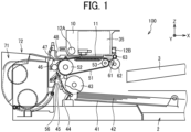
- FIG. 1 illustrates an overall configuration of an inkjet recording apparatus according to an embodiment of the present disclosure.
- a serial type inkjet recording apparatus that discharges ink as a liquid will be described as an example of a liquid discharge apparatus according to an embodiment of the present disclosure.
- a direction X is a sub-scanning direction
- a direction Y is a main scanning direction.
- the directions X, Y, and Z are orthogonal to each other.
- an inkjet recording apparatus 100 includes a carriage 10 in the upper portion thereof.
- the carriage 10 includes liquid discharge heads 11 that discharge ink droplets of colors of yellow (Y), cyan (C), magenta (M), and black (K).
- the carriage 10 includes a head tank 35 that supplies inks of the respective colors to the corresponding nozzle rows of the liquid discharge heads 11.
- the inks of the respective colors are supplied from ink cartridges of the respective colors to the head tank 35 via supply tubes of the respective colors.
- a sheet feeding unit is disposed above a sheet stacking portion (pressure plate) 41 of a sheet feeding tray 2.
- the sheet feeding unit feeds a sheet 42 as a recording medium stacked on the sheet stacking portion 41 toward a sheet guide 45.
- the sheet feeding unit includes a sheet feeding roller (semicircular roller) 43 and a separation pad 44.
- the sheet feeding roller (semicircular roller) 43 separates and feeds sheets 42 one by one from the sheet stacking portion 41.
- the separation pad 44 faces the sheet feeding roller 43 and is made of a material having a large friction coefficient. The separation pad 44 is pressed against the sheet feeding roller 43.
- the inkjet recording apparatus 100 includes the sheet guide 45, a counter roller 46, a conveyance guide 47, a pressing member 48, a conveyance belt 51, and a charging roller 56.
- the sheet guide 45 feeds the sheet 42 fed from the sheet feeding unit under the liquid discharge head 11.
- the conveyance belt 51 electrostatically attracts the fed sheet 42 and conveys the sheet 42 to a position facing the liquid discharge head 11.
- the conveyance belt 51 is an endless belt looped around a conveyance roller 52 and a tension roller 53.
- the charging roller 56 charges the surface of the conveyance belt 51.
- the charging roller 56 contacts a surface layer of the conveyance belt 51 and rotates along with the rotation of the conveyance belt 51.
- the conveyance roller 52 is rotationally driven by a sub-scanning motor via a timing belt, so that the conveyance belt 51 is rotated in a belt conveyance direction (the sub-scanning direction).
- the inkjet recording apparatus 100 also includes a sheet ejection unit that ejects the sheet 42 on which an object has been recorded by the liquid discharge head 11.
- the sheet ejection unit includes a separation claw 61, sheet ejection rollers 62 and 63, and a sheet ejection tray 3.
- the separation claw 61 separates the sheet 42 from the conveyance belt 51.
- the sheet ejection tray 3 is disposed below the sheet ejection roller 62.
- a duplex unit 71 is detachably attached to the rear portion of the inkjet recording apparatus 100. As the conveyance belt 51 rotates in the reverse direction to convey the sheet 42 backward, the duplex unit 71 takes in the sheet 42 conveyed backward. Then, the duplex unit 71 reverses the sheet 42 and feeds the sheet 42 again to the nip between the counter roller 46 and the conveyance belt 51.
- a manual sheet feeding tray 72 is disposed on the upper face of the duplex unit 71.
- the liquid discharge head 11 is driven in response to an image signal while the carriage 10 moves to perform a printing operation.
- the liquid discharge head 11 discharges droplets of ink to record an object such as characters or an image corresponding to one line on the sheet 42 not in motion. After the sheet 42 is conveyed by a predetermined amount, the liquid discharge head 11 records the object corresponding to the next line.
- the inkjet recording apparatus 100 receives a recording end signal or detects the arrival of the trailing end of the sheet 42 at the recording area, the printing operation is finished and the sheet 42 is ejected to the sheet ejection tray 3.
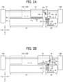
- FIGS. 2A and 2B are side views of a part of the inkjet recording apparatus 100.
- guide rods 12A and 12B as a pair of supports are laterally stretched between left and right side plates 13A and 13B.
- the guide rods 12A and 12B extend in the main scanning direction.
- the side plates 13A and 13B serve as a part of a housing of the inkjet recording apparatus 100.
- the support may be a guide rail.
- the carriage 10 and an auxiliary carriage 14 serving as a cover are supported by the guide rods 12A and 12B.
- the carriage 10 is movable in the main scanning direction along the guide rods 12A and 12B by a main scanning drive motor.
- the auxiliary carriage 14 moves in the main scanning direction along the guide rods 12A and 12B when the carriage 10 pushes the auxiliary carriage 14 or the carriage 10 coupled to the auxiliary carriage 14 moves (details will be described later).
- Each of the liquid discharge heads 11 mounted on the carriage 10 has a nozzle row in which multiple nozzles are arrayed in the sub-scanning direction.
- the liquid discharge head 11 has a discharge face 11a on which ends of the nozzles are arranged. Ink is discharged downward in FIG. 2A from the ends of the nozzles on the discharge face 11a.
- a printing area A1 as a liquid discharge region and a maintenance area A2 are arranged in the main scanning direction.
- the liquid discharge head 11 discharges liquid to the sheet 42 conveyed in the printing area A1 to perform the printing operation on the sheet 42.
- the maintenance area A2 is disposed on one side of the printing area A1 in the main scanning direction.
- the maintenance unit 20 and the auxiliary carriage 14 are disposed in the maintenance area A2.
- the maintenance unit 20 includes a cap 21, a suction pump 22, a waste liquid tube 23, a waste liquid tank 24, and a wiper 25 as a wiping member.
- the cap 21 covers the discharge face 11a of each liquid discharge head 11 as illustrated in FIG. 2B to prevent evaporation of moisture in the ink in the liquid discharge head 11 during a non-liquid discharge operation such as a maintenance mode.
- the cap 21 is movable in the vertical direction in FIG. 2B to approach and separate from the discharge face 11a.
- the cap 21 is connected to the suction pump 22 via a flexible waste liquid tube 23.
- the waste liquid tube 23 is connected to the waste liquid tank 24 on the side opposite to the side connected to the cap 21.
- the suction pump 22 performs a suction operation with the discharge face 11a covered by the cap 21 to drain ink adhering to the discharge face 11a or the inside of the nozzles to the waste liquid tank 24.
- the cap 21 according to the present embodiment has functions to retain moisture inside the liquid discharge head 11 and suck the remaining ink.
- the cap 21 may have only a function to cover the discharge face 11a to retain moisture.
- the wiper 25 wipes the discharge face 11a to remove, for example, ink adhering to the discharge face 11a.
- the wiper 25 is movable in the vertical direction in FIG. 2A .
- the auxiliary carriage 14 has a cover face 14a.
- the cover face 14a according to the present embodiment is flat.
- the cover face 14a contacts the side of the cap 21 that covers the discharge face 11a, to seal the cap 21.
- the cover face 14a is not limited to being flat as long as the cover face 14a can seal the cap 21, and other shapes such as a recessed shape can be appropriately adopted.
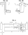
- the auxiliary carriage 14 includes a claw 15 as an engagement part. As illustrated in FIGS. 3A and 3B , the claw 15 is rotatable about a support shaft 15a (i.e., an axis). The claw 15 includes a first projection 15b and a second projection 15c that project in the sub-scanning direction (from the surface of the paper on which FIGS. 2A and 2B are drawn toward the back). As illustrated in FIGS. 2A and 2B , one side 15d of the claw 15 is an engaging portion that engages with an engaged portion 10a of the carriage 10.
- the carriage 10 is positioned in the printing area A1 during the printing operation (liquid discharge operation).
- the cap 21 moves upward and contacts the cover face 14a of the auxiliary carriage 14 positioned above the cap 21.
- the cap 21 is sealed by the cover face 14a. Accordingly, the inside of the cap 21 can be prevented from being opened to the outside air, and thus can be prevented from drying.
- the cap 21 is positioned at the top of the movable range thereof.
- the cap 21 moves downward and retracts from the cover face 14a as illustrated in FIG. 5 .
- the sealed state of the cap 21 is released.
- the carriage 10 moves from the printing area A1 to the maintenance area A2 and contacts the auxiliary carriage 14 at a contact position.
- the auxiliary carriage 14 is not coupled to the carriage 10. From this state, when a driving force for moving the carriage 10 in the direction indicated by arrow B1 in FIG. 6 is applied to the carriage 10, the carriage 10 pushes the auxiliary carriage 14. Thus, the carriage 10 moves in the direction indicated by arrow B1 together with the auxiliary carriage 14. As a result, the auxiliary carriage 14 moves from the position facing the cap 21 (i.e., a cap position).
- the carriage 10 With the auxiliary carriage 14 coupled to the carriage 10, the carriage 10 changes the movement direction thereof and moves in the direction indicated by arrow B3 as illustrated in FIG. 8 .
- the auxiliary carriage 14 moves in the direction indicated by arrow B3 following the carriage 10.
- the wiper 25 can wipe the cover face 14a of the auxiliary carriage 14.
- the cover face 14a seals the cap 21, ink adhering to the cap 21 is adhered to the cover face 14a.
- the wiper 25 can wipe off the ink adhering to the cover face 14a.
- the cap 21 covers the discharge face 11a of each liquid discharge head 11 to perform the suction operation by the suction pump 22, or a wiping operation of the discharge face 11a of each liquid discharge head 11 is performed by the wiper 25 at a wiper position.
- the second projection 15c (see FIG. 3B ) of the claw 15 contacts a second pin 102 (see FIGS. 12A to 12D ) attached to, for example, the housing of the inkjet recording apparatus 100.
- the claw 15 rotates clockwise in FIG. 8 , and the claw 15 disengages from the engaged portion 10a of the carriage 10 as illustrated in FIG. 9 .
- the second projection 15c of the claw 15 contacts the second pin 102 as illustrated in FIG.
- the auxiliary carriage 14 having the cover face 14a can reciprocally move between the position where the cover face 14a covers the cap 21 and the position where the cover face 14a is retracted from above the cap 21 without a dedicated driving source.
- the auxiliary carriage 14 is supported by the guide rods 12A and 12B, and can be coupled to and decoupled from the carriage 10.
- the auxiliary carriage 14 can move along the guide rods 12A and 12B in the direction indicated by arrow B1 in FIG. 5 .
- the auxiliary carriage 14 can move in the direction indicated by arrow B3 in FIG. 8 following the carriage 10 to which the auxiliary carriage 14 is coupled.
- the auxiliary carriage 14 moves to the position facing the cap 21 (see FIG. 4 ).
- the auxiliary carriage 14 moves to the position retracted from the cap 21 (see FIG. 7 ), and the cap 21 covers the discharge face 11a of the liquid discharge head 11.
- the auxiliary carriage 14 can be moved without a dedicated driving source, and the structure of the liquid discharge apparatus can be simplified.
- the auxiliary carriage 14 coupled to the carriage 10 is movable to the left in FIG. 8 . Accordingly, the auxiliary carriage 14 can be moved to the position facing the wiper 25, and the wiping operation of the cover face 14a of the auxiliary carriage 14 can be performed by the wiper 25.
- the auxiliary carriage 14 is not coupled to a dedicated drive mechanism and is supported by the guide rods 12A and 12B. Accordingly, the auxiliary carriage 14 can be easily attached and detached, and the structure of the liquid discharge apparatus can be simplified.
- the auxiliary carriage 14 is decoupled from the carriage 10 at a decoupling position, i.e., at least at the position where the auxiliary carriage 14 faces the cap 21 (the position illustrated in FIG. 4 ) or at a position on the left from the cap 21 in FIG. 2A in the main scanning direction (i.e., between the cap position and the liquid discharge region). Accordingly, the auxiliary carriage 14 remains at the position where the auxiliary carriage 14 is decoupled from the carriage 10, or the auxiliary carriage 14 is pushed by the carriage 10 to the right in FIG. 2A in the main scanning direction after the decoupling to position the auxiliary carriage 14 at the position facing the cap 21 again as illustrated in FIG. 4 .
- the auxiliary carriage 14 is coupled to the carriage 10 at any position where the carriage 10 is in contact with the auxiliary carriage 14 on the right from the decoupling position in FIG. 2A in the main scanning direction.
- the auxiliary carriage 14 can be coupled to the carriage 10 and moved together with the carriage 10 within a desired range in the main scanning direction.
- the auxiliary carriage 14 may have a cleaning nozzle 16 as a cleaning liquid supplier.
- the cleaning nozzle 16 is connected to, for example, a cleaning liquid tank that stores a cleaning liquid.
- the auxiliary carriage 14 has an end of the cleaning nozzle 16 on the cover face 14a and supplies the cleaning liquid to the cap 21 from the cleaning nozzle 16. Thus, the cap 21 can be cleaned.
- the liquid to be discharged is not limited to a particular liquid as long as the liquid has a viscosity or surface tension to be discharged from a head (liquid discharge head).
- the viscosity of the liquid is not greater than 30 millipascal-second (mPa ⁇ s) under ordinary temperature and ordinary pressure or by heating or cooling.
- Examples of the material to be discharged include a solution, a suspension, or an emulsion including, for example, a solvent, such as water or an organic solvent; a colorant, such as dye or pigment; a functional material, such as a polymerizable compound, a resin, or a surfactant; a biocompatible material, such as deoxyribonucleic acid (DNA), amino acid, protein, or calcium; and an edible material, such as a natural colorant.
- a solution, a suspension, or an emulsion can be used for, e.g., inkjet ink; surface treatment liquid; a liquid for forming an electronic element component, a light-emitting element component, or an electronic circuit resist pattern; or a material solution for three-dimensional fabrication.
- liquid includes not only ink but also paint, a pretreatment liquid, a binder, and an overcoat liquid.
- liquid discharge apparatus includes a carriage including a liquid discharge head and drives the liquid discharge head to discharge liquid.
- liquid discharge apparatus used herein includes, in addition to apparatuses to discharge liquid to a recording medium serving as a medium onto which liquid can adhere, apparatuses to discharge liquid into gas (air) or different liquid.
- the "liquid discharge apparatus” may further include devices relating to feeding, conveying, and ejecting of the medium onto which liquid can adhere and also include a pretreatment device and an aftertreatment device.
- the "liquid discharge apparatus” may be, for example, an image forming apparatus to form an image on a sheet by discharging ink, or a three-dimensional fabrication apparatus to discharge fabrication liquid to a powder layer in which powder material is formed in layers to form a three-dimensional object.
- liquid discharge apparatus is not limited to an apparatus that discharges liquid to visualize meaningful images such as letters or figures.
- the liquid discharge apparatus may be an apparatus that forms patterns having no meaning or an apparatus that fabricates three-dimensional images.
- the above-described term "medium onto which liquid can adhere” represents a medium on which liquid is at least temporarily adhered, a medium on which liquid is adhered and fixed, or a medium into which liquid adheres and permeates.
- Specific examples of the "medium onto which liquid can adhere” include, but are not limited to, a recording medium such as a paper sheet, recording paper, a recording sheet of paper, a film, or cloth, an electronic component such as an electronic substrate or a piezoelectric element, and a medium such as layered powder, an organ model, or a testing cell.
- the "medium onto which liquid can adhere” includes any medium to which liquid adheres, unless otherwise specified.
- Examples of materials of the "medium onto which liquid can adhere” include any materials to which liquid can adhere even temporarily, such as paper, thread, fiber, fabric, leather, metal, plastic, glass, wood, and ceramic.
- Examples of the liquid discharge apparatus further include: a treatment liquid applying apparatus that discharges a treatment liquid onto a sheet to apply the treatment liquid to the surface of the sheet, for reforming the surface of the sheet; and an injection granulation apparatus that injects a composition liquid, in which a raw material is dispersed in a solution, through a nozzle to granulate fine particle of the raw material.
- a treatment liquid applying apparatus that discharges a treatment liquid onto a sheet to apply the treatment liquid to the surface of the sheet, for reforming the surface of the sheet
- an injection granulation apparatus that injects a composition liquid, in which a raw material is dispersed in a solution, through a nozzle to granulate fine particle of the raw material.
- image formation means “image formation,” “recording,” “printing,” “image printing,” and “fabricating” used herein may be used synonymously with each other.
- a liquid discharge apparatus includes a carriage including a liquid discharge head, a support extending in a main scanning direction and supporting the carriage movably in the main scanning direction, a cap to cover a discharge face of the liquid discharge head, and a cover to cover the cap.
- the cover is supported movably in the main scanning direction by the support. The cover can be coupled to and decoupled from the carriage.
- a liquid discharge apparatus includes a liquid discharge head, a carriage, a cap, a cover, and a support.
- the liquid discharge head has a discharge face and discharges a liquid from the discharge face to perform a liquid discharge operation.
- the carriage mounts the liquid discharge head and is movable in main scanning directions.
- the cap covers the discharge face of the liquid discharge head.
- the cover covers the cap.
- the cover is decouplable from and couplable to the carriage, and movable in the main scanning directions.
- the support extends in the main scanning directions and supports the carriage and the cover movable in the main scanning directions.
- the cover covers the cap during a liquid discharge operation by the liquid discharge head.
- the cover covers the cap in the liquid discharge operation.
- the cover is moved to one side in the main scanning direction by being pushed by the carriage and moved to the other side in the main scanning direction by the carriage being moved to the other side in the main scanning direction with the cover coupled to the carriage.
- the carriage moves in a first direction of the main scanning directions to push and move the cover in the first direction, and the carriage moves in a second direction opposite to the first direction to move the cover coupled to the carriage in the second direction.
- a region in which the liquid discharge head discharges a liquid onto a recording medium is a liquid discharge region.
- the cap is disposed outside the liquid discharge region.
- the cover is decoupled from the carriage at a position where the cover faces the cap or at a position closer to the liquid discharge region than the position.
- the liquid discharge head discharges the liquid onto a medium in a liquid discharge region.
- the cap is at a cap position outside the liquid discharge region.
- the cover is decoupled from the carriage at a decoupling position between the cap position and the liquid discharge region. The cover faces the cap at the cap position.
- the carriage moves from the liquid discharge region toward the cover, and the carriage and the cover are coupled to each other at a position on the one side in the main scanning direction from a position where the carriage contacts the cover and on the one side in the main scanning direction from a position where the cover is decoupled from the carriage.
- the carriage moves from the liquid discharge region toward the cover in the first direction and contacts the cover at a contact position.
- the cover is coupled to the carriage at a coupling position farther from the liquid discharge region than the contact position and the decoupling position in the first direction.
- the liquid discharge apparatus further includes a wiper to wipe the discharge face.
- the cover moves to a position facing the wiper and is wiped by the wiper.
- the liquid discharge apparatus further includes a wiper to wipe the discharge face at a wiper position.
- the wiper wipes the cover moved to the wiper position.
- the cover includes an engagement part that is rotatable.
- the carriage has a portion to be engaged.
- An engaging portion of the engagement part engages with the portion to be engaged by rotation of the engagement part, and the cover is coupled to the carriage.
- the cover includes an engagement part having an engaging portion and an axis around which the engagement part is rotatable between an engaged position and a disengaged position.
- the carriage has an engaged portion engageable with the engagement part of the cover. The engaging portion of the cover rotated toward the engaged position engages with the engaged portion of the carriage to couple the cover to the carriage.
- the cover includes a cleaning liquid supplier.
- the cover includes a cleaning liquid supplier to supply a cleaning liquid to the cap.
Landscapes
- Ink Jet (AREA)
Abstract
Description
- Embodiments of the present disclosure relate to a liquid discharge apparatus.
- In the related art, a liquid discharge apparatus includes a cap that covers a discharge face of a liquid discharge head. The cap sucks liquid from nozzles of the liquid discharge head and keeps moisture in the nozzles at times other than a liquid discharge operation. However, depending on the type of liquid, the liquid may be fixed (adhered) and deposited in the cap due to properties such as high viscosity, low solubility, and fast drying.
- In
Japanese Unexamined Patent Application Publication No. 2002-316421 Japanese Unexamined Patent Application Publication No. 2002-316421 - The present disclosure has an object to provide a liquid discharge apparatus in which a cover is movable between a position where the cover covers the cap and a position where the cover is retracted from the cap with a simple configuration.
- Embodiments of the present disclosure describe an improved liquid discharge apparatus that includes a liquid discharge head, a carriage, a cap, a cover, and a support. The liquid discharge head has a discharge face and discharges a liquid from the discharge face to perform a liquid discharge operation. The carriage mounts the liquid discharge head and is movable in main scanning directions. The cap covers the discharge face of the liquid discharge head. The cover covers the cap. The cover is decouplable from and couplable to the carriage, and movable in the main scanning directions. The support extends in the main scanning directions and supports the carriage and the cover movable in the main scanning directions.
- As a result, according to one aspect of the present disclosure, the cover is movable between the position where the cover covers the cap and the position where the cover is retracted from the cap with a simple configuration.
- A more complete appreciation of the disclosure and many of the attendant advantages and features thereof can be readily obtained and understood from the following detailed description with reference to the accompanying drawings, wherein:
-
FIG. 1 is a schematic view of a liquid discharge apparatus according to an embodiment of the present disclosure; -
FIGS. 2A and 2B are side views of a liquid discharge apparatus according to an embodiment of the present disclosure; -
FIGS. 3A and 3B are perspective views of a claw according to an embodiment of the present disclosure; -
FIG. 4 is a side view of the liquid discharge apparatus ofFIGS. 2A and 2B , illustrating a series of operations of an auxiliary carriage in a maintenance mode; -
FIG. 5 is a side view of the liquid discharge apparatus ofFIGS. 2A and 2B , illustrating the series of operations of the auxiliary carriage in the maintenance mode; -
FIG. 6 is a side view of the liquid discharge apparatus ofFIGS. 2A and 2B , illustrating the series of operations of the auxiliary carriage in the maintenance mode; -
FIG. 7 is a side view of the liquid discharge apparatus ofFIGS. 2A and 2B , illustrating the series of operations of the auxiliary carriage in the maintenance mode; -
FIG. 8 is a side view of the liquid discharge apparatus ofFIGS. 2A and 2B , illustrating the series of operations of the auxiliary carriage in the maintenance mode; -
FIG. 9 is a side view of the liquid discharge apparatus ofFIGS. 2A and 2B , illustrating the series of operations of the auxiliary carriage in the maintenance mode; -
FIG. 10 is a side view of the liquid discharge apparatus ofFIGS. 2A and 2B , illustrating the series of operations of the auxiliary carriage in the maintenance mode; -
FIGS. 11A to 11C are diagrams of the claw ofFIGS. 3A and 3B , which is rotated counterclockwise by a first pin; -
FIGS. 12A to 12D are diagrams of the claw ofFIGS. 3A and 3B , which is rotated clockwise by a second pin; and -
FIG. 13 is a diagram of an auxiliary carriage for supplying a cleaning liquid, according to an embodiment of the present disclosure. - The accompanying drawings are intended to depict embodiments of the present invention and should not be interpreted to limit the scope thereof. The accompanying drawings are not to be considered as drawn to scale unless explicitly noted. Also, identical or similar reference numerals designate identical or similar components throughout the several views.
- In describing embodiments illustrated in the drawings, specific terminology is employed for the sake of clarity. However, the disclosure of this specification is not intended to be limited to the specific terminology so selected and it is to be understood that each specific element includes all technical equivalents that have a similar function, operate in a similar manner, and achieve a similar result.
- Referring now to the drawings, embodiments of the present disclosure are described below. As used herein, the singular forms "a," "an," and "the" are intended to include the plural forms as well, unless the context clearly indicates otherwise.
- Embodiments of the present disclosure are described below with reference to the drawings. In the drawings, like reference signs denote like elements, and overlapping description may be simplified or omitted as appropriate.
-
FIG. 1 illustrates an overall configuration of an inkjet recording apparatus according to an embodiment of the present disclosure. In the following description, a serial type inkjet recording apparatus that discharges ink as a liquid will be described as an example of a liquid discharge apparatus according to an embodiment of the present disclosure. InFIG. 1 , a direction X is a sub-scanning direction, and a direction Y is a main scanning direction. The directions X, Y, and Z are orthogonal to each other. - As illustrated in
FIG. 1 , aninkjet recording apparatus 100 includes acarriage 10 in the upper portion thereof. Thecarriage 10 includesliquid discharge heads 11 that discharge ink droplets of colors of yellow (Y), cyan (C), magenta (M), and black (K). - The
carriage 10 includes ahead tank 35 that supplies inks of the respective colors to the corresponding nozzle rows of the liquid discharge heads 11. The inks of the respective colors are supplied from ink cartridges of the respective colors to thehead tank 35 via supply tubes of the respective colors. - A sheet feeding unit is disposed above a sheet stacking portion (pressure plate) 41 of a
sheet feeding tray 2. The sheet feeding unit feeds asheet 42 as a recording medium stacked on thesheet stacking portion 41 toward asheet guide 45. The sheet feeding unit includes a sheet feeding roller (semicircular roller) 43 and aseparation pad 44. The sheet feeding roller (semicircular roller) 43 separates and feedssheets 42 one by one from thesheet stacking portion 41. Theseparation pad 44 faces thesheet feeding roller 43 and is made of a material having a large friction coefficient. Theseparation pad 44 is pressed against thesheet feeding roller 43. - The
inkjet recording apparatus 100 includes thesheet guide 45, acounter roller 46, aconveyance guide 47, a pressingmember 48, aconveyance belt 51, and a chargingroller 56. Thesheet guide 45 feeds thesheet 42 fed from the sheet feeding unit under theliquid discharge head 11. Theconveyance belt 51 electrostatically attracts the fedsheet 42 and conveys thesheet 42 to a position facing theliquid discharge head 11. Theconveyance belt 51 is an endless belt looped around aconveyance roller 52 and atension roller 53. The chargingroller 56 charges the surface of theconveyance belt 51. The chargingroller 56 contacts a surface layer of theconveyance belt 51 and rotates along with the rotation of theconveyance belt 51. Theconveyance roller 52 is rotationally driven by a sub-scanning motor via a timing belt, so that theconveyance belt 51 is rotated in a belt conveyance direction (the sub-scanning direction). - The
inkjet recording apparatus 100 also includes a sheet ejection unit that ejects thesheet 42 on which an object has been recorded by theliquid discharge head 11. The sheet ejection unit includes aseparation claw 61,sheet ejection rollers sheet ejection tray 3. Theseparation claw 61 separates thesheet 42 from theconveyance belt 51. Thesheet ejection tray 3 is disposed below thesheet ejection roller 62. - A
duplex unit 71 is detachably attached to the rear portion of theinkjet recording apparatus 100. As theconveyance belt 51 rotates in the reverse direction to convey thesheet 42 backward, theduplex unit 71 takes in thesheet 42 conveyed backward. Then, theduplex unit 71 reverses thesheet 42 and feeds thesheet 42 again to the nip between thecounter roller 46 and theconveyance belt 51. A manualsheet feeding tray 72 is disposed on the upper face of theduplex unit 71. - The
liquid discharge head 11 is driven in response to an image signal while thecarriage 10 moves to perform a printing operation. Theliquid discharge head 11 discharges droplets of ink to record an object such as characters or an image corresponding to one line on thesheet 42 not in motion. After thesheet 42 is conveyed by a predetermined amount, theliquid discharge head 11 records the object corresponding to the next line. When theinkjet recording apparatus 100 receives a recording end signal or detects the arrival of the trailing end of thesheet 42 at the recording area, the printing operation is finished and thesheet 42 is ejected to thesheet ejection tray 3. -
FIGS. 2A and 2B are side views of a part of theinkjet recording apparatus 100. - As illustrated in
FIGS. 2A and 2B , guiderods right side plates guide rods side plates inkjet recording apparatus 100. The support may be a guide rail. - The
carriage 10 and anauxiliary carriage 14 serving as a cover are supported by theguide rods carriage 10 is movable in the main scanning direction along theguide rods auxiliary carriage 14 moves in the main scanning direction along theguide rods carriage 10 pushes theauxiliary carriage 14 or thecarriage 10 coupled to theauxiliary carriage 14 moves (details will be described later). - Each of the liquid discharge heads 11 mounted on the
carriage 10 has a nozzle row in which multiple nozzles are arrayed in the sub-scanning direction. Theliquid discharge head 11 has adischarge face 11a on which ends of the nozzles are arranged. Ink is discharged downward inFIG. 2A from the ends of the nozzles on thedischarge face 11a. - A printing area A1 as a liquid discharge region and a maintenance area A2 are arranged in the main scanning direction. The
liquid discharge head 11 discharges liquid to thesheet 42 conveyed in the printing area A1 to perform the printing operation on thesheet 42. The maintenance area A2 is disposed on one side of the printing area A1 in the main scanning direction. - The
maintenance unit 20 and theauxiliary carriage 14 are disposed in the maintenance area A2. Themaintenance unit 20 includes acap 21, asuction pump 22, awaste liquid tube 23, awaste liquid tank 24, and awiper 25 as a wiping member. - The
cap 21 covers thedischarge face 11a of eachliquid discharge head 11 as illustrated inFIG. 2B to prevent evaporation of moisture in the ink in theliquid discharge head 11 during a non-liquid discharge operation such as a maintenance mode. Thecap 21 is movable in the vertical direction inFIG. 2B to approach and separate from thedischarge face 11a. Thecap 21 is connected to thesuction pump 22 via a flexiblewaste liquid tube 23. Thewaste liquid tube 23 is connected to thewaste liquid tank 24 on the side opposite to the side connected to thecap 21. Thesuction pump 22 performs a suction operation with thedischarge face 11a covered by thecap 21 to drain ink adhering to thedischarge face 11a or the inside of the nozzles to thewaste liquid tank 24. Thus, thecap 21 according to the present embodiment has functions to retain moisture inside theliquid discharge head 11 and suck the remaining ink. However, thecap 21 may have only a function to cover thedischarge face 11a to retain moisture. - The
wiper 25 wipes thedischarge face 11a to remove, for example, ink adhering to thedischarge face 11a. Thewiper 25 is movable in the vertical direction inFIG. 2A . - The
auxiliary carriage 14 has acover face 14a. Thecover face 14a according to the present embodiment is flat. Thecover face 14a contacts the side of thecap 21 that covers thedischarge face 11a, to seal thecap 21. Thecover face 14a is not limited to being flat as long as thecover face 14a can seal thecap 21, and other shapes such as a recessed shape can be appropriately adopted. - The
auxiliary carriage 14 includes aclaw 15 as an engagement part. As illustrated inFIGS. 3A and 3B , theclaw 15 is rotatable about asupport shaft 15a (i.e., an axis). Theclaw 15 includes afirst projection 15b and asecond projection 15c that project in the sub-scanning direction (from the surface of the paper on whichFIGS. 2A and 2B are drawn toward the back). As illustrated inFIGS. 2A and 2B , oneside 15d of theclaw 15 is an engaging portion that engages with an engagedportion 10a of thecarriage 10. - A description will be given below of a procedure in which the
cover face 14a of theauxiliary carriage 14 is switched between a state of covering thecap 21 and a state of retracting theauxiliary carriage 14 from thecap 21 in the maintenance mode with reference toFIGS. 4 to 12D . - As illustrated in
FIG. 4 , thecarriage 10 is positioned in the printing area A1 during the printing operation (liquid discharge operation). Thecap 21 moves upward and contacts thecover face 14a of theauxiliary carriage 14 positioned above thecap 21. As a result, thecap 21 is sealed by thecover face 14a. Accordingly, the inside of thecap 21 can be prevented from being opened to the outside air, and thus can be prevented from drying. Thecap 21 is positioned at the top of the movable range thereof. - When the printing operation is interrupted or finished and the maintenance operation is started, the
cap 21 moves downward and retracts from thecover face 14a as illustrated inFIG. 5 . Thus, the sealed state of thecap 21 is released. - Subsequently, as illustrated in
FIG. 6 , thecarriage 10 moves from the printing area A1 to the maintenance area A2 and contacts theauxiliary carriage 14 at a contact position. - In this state, the
auxiliary carriage 14 is not coupled to thecarriage 10. From this state, when a driving force for moving thecarriage 10 in the direction indicated by arrow B1 inFIG. 6 is applied to thecarriage 10, thecarriage 10 pushes theauxiliary carriage 14. Thus, thecarriage 10 moves in the direction indicated by arrow B1 together with theauxiliary carriage 14. As a result, theauxiliary carriage 14 moves from the position facing the cap 21 (i.e., a cap position). - When the
auxiliary carriage 14 moves in the direction indicated by arrow B 1 inFIG. 6 , thefirst projection 15b (seeFIG. 3B ) of theclaw 15 contacts a first pin 101 (seeFIGS. 11A to 11C ) attached to, for example, the housing of theinkjet recording apparatus 100. As a result, from the state illustrated inFIG. 6 to the state illustrated inFIG. 7 , theclaw 15 rotates counterclockwise inFIG. 6 , and the oneside 15d of theclaw 15 engages with the engagedportion 10a of thecarriage 10 as illustrated inFIG. 7 . Specifically, as illustrated inFIG. 11A , when theclaw 15 moves in the direction indicated by arrow B 1 along with the movement of theauxiliary carriage 14, thefirst projection 15b of theclaw 15 contacts thefirst pin 101 as illustrated inFIG. 11B , and force is applied to thefirst projection 15b. As a result, theclaw 15 rotates in the direction indicated by arrow B2 inFIG. 11B about thesupport shaft 15a, and the oneside 15d of theclaw 15 engages with the engagedportion 10a as illustrated inFIG. 11C (i.e., an engaged position). As a result, theauxiliary carriage 14 is coupled to thecarriage 10 at a coupling position as illustrated inFIG. 7 . - With the
auxiliary carriage 14 coupled to thecarriage 10, thecarriage 10 changes the movement direction thereof and moves in the direction indicated by arrow B3 as illustrated inFIG. 8 . Theauxiliary carriage 14 moves in the direction indicated by arrow B3 following thecarriage 10. At this time, if thewiper 25 is moved upward, thewiper 25 can wipe thecover face 14a of theauxiliary carriage 14. When thecover face 14a seals thecap 21, ink adhering to thecap 21 is adhered to thecover face 14a. Thewiper 25 can wipe off the ink adhering to thecover face 14a. When thecarriage 10 is positioned in the maintenance area A2, thecap 21 covers thedischarge face 11a of eachliquid discharge head 11 to perform the suction operation by thesuction pump 22, or a wiping operation of thedischarge face 11a of eachliquid discharge head 11 is performed by thewiper 25 at a wiper position. - When the
carriage 10 and theauxiliary carriage 14 further move in the direction indicated by arrow B3, thesecond projection 15c (seeFIG. 3B ) of theclaw 15 contacts a second pin 102 (seeFIGS. 12A to 12D ) attached to, for example, the housing of theinkjet recording apparatus 100. As a result, from the state illustrated inFIG. 8 to the state illustrated inFIG. 9 , theclaw 15 rotates clockwise inFIG. 8 , and theclaw 15 disengages from the engagedportion 10a of thecarriage 10 as illustrated inFIG. 9 . Specifically, as illustrated inFIG. 12A , when theclaw 15 moves in the direction indicated by arrow B3 along with the movement of theauxiliary carriage 14, thesecond projection 15c of theclaw 15 contacts thesecond pin 102 as illustrated inFIG. 12B , and force is applied to thesecond projection 15c. As a result, theclaw 15 rotates in the direction indicated by arrow B4 inFIG. 12C about thesupport shaft 15a as illustrated inFIG. 12C , and theclaw 15 disengages from the engagedportion 10a as illustrated inFIG. 12D (i.e., a disengaged position). As a result, theauxiliary carriage 14 is decoupled from thecarriage 10 as illustrated inFIG. 9 . - From this state, as illustrated in
FIG. 10 , thecarriage 10 moves in the direction indicated by arrow B1 and pushes theauxiliary carriage 14 to move theauxiliary carriage 14 to the position facing thecap 21 again. Subsequently, thecarriage 10 moves to the left inFIG. 10 , and only thecarriage 10 moves to the printing area A1. Thecap 21 is moved upward and is covered by thecover face 14a of theauxiliary carriage 14 to return to the state illustrated inFIG. 4 again. Each component such as thecarriage 10 is operated as described above in the maintenance mode. - As described above, in the present embodiment, the
auxiliary carriage 14 having thecover face 14a can reciprocally move between the position where thecover face 14a covers thecap 21 and the position where thecover face 14a is retracted from above thecap 21 without a dedicated driving source. In the present embodiment, theauxiliary carriage 14 is supported by theguide rods carriage 10. Thus, as thecarriage 10 pushes theauxiliary carriage 14, theauxiliary carriage 14 can move along theguide rods FIG. 5 . Theauxiliary carriage 14 can move in the direction indicated by arrow B3 inFIG. 8 following thecarriage 10 to which theauxiliary carriage 14 is coupled. Accordingly, to cover thecap 21 by thecover face 14a of theauxiliary carriage 14, theauxiliary carriage 14 moves to the position facing the cap 21 (seeFIG. 4 ). During the maintenance operation of eachliquid discharge head 11 by themaintenance unit 20, theauxiliary carriage 14 moves to the position retracted from the cap 21 (seeFIG. 7 ), and thecap 21 covers thedischarge face 11a of theliquid discharge head 11. - As described above, the
auxiliary carriage 14 can be moved without a dedicated driving source, and the structure of the liquid discharge apparatus can be simplified. Theauxiliary carriage 14 coupled to thecarriage 10 is movable to the left inFIG. 8 . Accordingly, theauxiliary carriage 14 can be moved to the position facing thewiper 25, and the wiping operation of thecover face 14a of theauxiliary carriage 14 can be performed by thewiper 25. As described above, theauxiliary carriage 14 is not coupled to a dedicated drive mechanism and is supported by theguide rods auxiliary carriage 14 can be easily attached and detached, and the structure of the liquid discharge apparatus can be simplified. - The
auxiliary carriage 14 is decoupled from thecarriage 10 at a decoupling position, i.e., at least at the position where theauxiliary carriage 14 faces the cap 21 (the position illustrated inFIG. 4 ) or at a position on the left from thecap 21 inFIG. 2A in the main scanning direction (i.e., between the cap position and the liquid discharge region). Accordingly, theauxiliary carriage 14 remains at the position where theauxiliary carriage 14 is decoupled from thecarriage 10, or theauxiliary carriage 14 is pushed by thecarriage 10 to the right inFIG. 2A in the main scanning direction after the decoupling to position theauxiliary carriage 14 at the position facing thecap 21 again as illustrated inFIG. 4 . Theauxiliary carriage 14 is coupled to thecarriage 10 at any position where thecarriage 10 is in contact with theauxiliary carriage 14 on the right from the decoupling position inFIG. 2A in the main scanning direction. Thus, theauxiliary carriage 14 can be coupled to thecarriage 10 and moved together with thecarriage 10 within a desired range in the main scanning direction. - As illustrated in
FIG. 13 , theauxiliary carriage 14 may have a cleaningnozzle 16 as a cleaning liquid supplier. The cleaningnozzle 16 is connected to, for example, a cleaning liquid tank that stores a cleaning liquid. Theauxiliary carriage 14 has an end of the cleaningnozzle 16 on thecover face 14a and supplies the cleaning liquid to thecap 21 from the cleaningnozzle 16. Thus, thecap 21 can be cleaned. - The above-described embodiments are illustrative and do not limit the present disclosure. Numerous additional modifications and variations are possible in light of the above teachings. It is therefore to be understood that within the scope of the appended claims.
- In the present disclosure, the liquid to be discharged is not limited to a particular liquid as long as the liquid has a viscosity or surface tension to be discharged from a head (liquid discharge head). However, preferably, the viscosity of the liquid is not greater than 30 millipascal-second (mPa·s) under ordinary temperature and ordinary pressure or by heating or cooling. Examples of the material to be discharged include a solution, a suspension, or an emulsion including, for example, a solvent, such as water or an organic solvent; a colorant, such as dye or pigment; a functional material, such as a polymerizable compound, a resin, or a surfactant; a biocompatible material, such as deoxyribonucleic acid (DNA), amino acid, protein, or calcium; and an edible material, such as a natural colorant. Such a solution, a suspension, or an emulsion can be used for, e.g., inkjet ink; surface treatment liquid; a liquid for forming an electronic element component, a light-emitting element component, or an electronic circuit resist pattern; or a material solution for three-dimensional fabrication.
- The term "liquid" includes not only ink but also paint, a pretreatment liquid, a binder, and an overcoat liquid.
- In the present disclosure, the term "liquid discharge apparatus" includes a carriage including a liquid discharge head and drives the liquid discharge head to discharge liquid. The term "liquid discharge apparatus" used herein includes, in addition to apparatuses to discharge liquid to a recording medium serving as a medium onto which liquid can adhere, apparatuses to discharge liquid into gas (air) or different liquid.
- For example, the "liquid discharge apparatus" may further include devices relating to feeding, conveying, and ejecting of the medium onto which liquid can adhere and also include a pretreatment device and an aftertreatment device.
- The "liquid discharge apparatus" may be, for example, an image forming apparatus to form an image on a sheet by discharging ink, or a three-dimensional fabrication apparatus to discharge fabrication liquid to a powder layer in which powder material is formed in layers to form a three-dimensional object.
- The "liquid discharge apparatus" is not limited to an apparatus that discharges liquid to visualize meaningful images such as letters or figures. For example, the liquid discharge apparatus may be an apparatus that forms patterns having no meaning or an apparatus that fabricates three-dimensional images.
- The above-described term "medium onto which liquid can adhere" represents a medium on which liquid is at least temporarily adhered, a medium on which liquid is adhered and fixed, or a medium into which liquid adheres and permeates. Specific examples of the "medium onto which liquid can adhere" include, but are not limited to, a recording medium such as a paper sheet, recording paper, a recording sheet of paper, a film, or cloth, an electronic component such as an electronic substrate or a piezoelectric element, and a medium such as layered powder, an organ model, or a testing cell. The "medium onto which liquid can adhere" includes any medium to which liquid adheres, unless otherwise specified.
- Examples of materials of the "medium onto which liquid can adhere" include any materials to which liquid can adhere even temporarily, such as paper, thread, fiber, fabric, leather, metal, plastic, glass, wood, and ceramic.
- Examples of the liquid discharge apparatus further include: a treatment liquid applying apparatus that discharges a treatment liquid onto a sheet to apply the treatment liquid to the surface of the sheet, for reforming the surface of the sheet; and an injection granulation apparatus that injects a composition liquid, in which a raw material is dispersed in a solution, through a nozzle to granulate fine particle of the raw material.
- The terms "image formation," "recording," "printing," "image printing," and "fabricating" used herein may be used synonymously with each other.
- Aspects of the present disclosure are, for example, as follows.
- A liquid discharge apparatus includes a carriage including a liquid discharge head, a support extending in a main scanning direction and supporting the carriage movably in the main scanning direction, a cap to cover a discharge face of the liquid discharge head, and a cover to cover the cap. The cover is supported movably in the main scanning direction by the support. The cover can be coupled to and decoupled from the carriage.
- In other words, a liquid discharge apparatus includes a liquid discharge head, a carriage, a cap, a cover, and a support. The liquid discharge head has a discharge face and discharges a liquid from the discharge face to perform a liquid discharge operation. The carriage mounts the liquid discharge head and is movable in main scanning directions. The cap covers the discharge face of the liquid discharge head. The cover covers the cap. The cover is decouplable from and couplable to the carriage, and movable in the main scanning directions. The support extends in the main scanning directions and supports the carriage and the cover movable in the main scanning directions.
- In the liquid discharge apparatus according to Aspect 1, the cover covers the cap during a liquid discharge operation by the liquid discharge head.
- In other words, the cover covers the cap in the liquid discharge operation.
- In the liquid discharge apparatus according to
Aspect 1 or 2, the cover is moved to one side in the main scanning direction by being pushed by the carriage and moved to the other side in the main scanning direction by the carriage being moved to the other side in the main scanning direction with the cover coupled to the carriage. - In other words, the carriage moves in a first direction of the main scanning directions to push and move the cover in the first direction, and the carriage moves in a second direction opposite to the first direction to move the cover coupled to the carriage in the second direction.
- In the liquid discharge apparatus according to
Aspect 3, a region in which the liquid discharge head discharges a liquid onto a recording medium is a liquid discharge region. - The cap is disposed outside the liquid discharge region. The cover is decoupled from the carriage at a position where the cover faces the cap or at a position closer to the liquid discharge region than the position.
- In other words, the liquid discharge head discharges the liquid onto a medium in a liquid discharge region. The cap is at a cap position outside the liquid discharge region. The cover is decoupled from the carriage at a decoupling position between the cap position and the liquid discharge region. The cover faces the cap at the cap position.
- In the liquid discharge apparatus according to Aspect 4, the carriage moves from the liquid discharge region toward the cover, and the carriage and the cover are coupled to each other at a position on the one side in the main scanning direction from a position where the carriage contacts the cover and on the one side in the main scanning direction from a position where the cover is decoupled from the carriage.
- In other words, the carriage moves from the liquid discharge region toward the cover in the first direction and contacts the cover at a contact position. The cover is coupled to the carriage at a coupling position farther from the liquid discharge region than the contact position and the decoupling position in the first direction.
- The liquid discharge apparatus according to any one of Aspects 1 to 5, further includes a wiper to wipe the discharge face. The cover moves to a position facing the wiper and is wiped by the wiper.
- In other words, the liquid discharge apparatus according to any one of Aspects 1 to 5, further includes a wiper to wipe the discharge face at a wiper position. The wiper wipes the cover moved to the wiper position.
- In the liquid discharge apparatus according to any one of Aspects 1 to 6, the cover includes an engagement part that is rotatable. The carriage has a portion to be engaged. An engaging portion of the engagement part engages with the portion to be engaged by rotation of the engagement part, and the cover is coupled to the carriage.
- In other words, the cover includes an engagement part having an engaging portion and an axis around which the engagement part is rotatable between an engaged position and a disengaged position. The carriage has an engaged portion engageable with the engagement part of the cover. The engaging portion of the cover rotated toward the engaged position engages with the engaged portion of the carriage to couple the cover to the carriage.
- The liquid discharge apparatus according to any one of Aspects 1 to 7, the cover includes a cleaning liquid supplier.
- In other words, the cover includes a cleaning liquid supplier to supply a cleaning liquid to the cap.
Claims (8)
- A liquid discharge apparatus (100) comprising:a liquid discharge head (11) having a discharge face (11a) to discharge a liquid from the discharge face (11a) to perform a liquid discharge operation;a carriage (10) mounting the liquid discharge head (11), the carriage (10) movable in main scanning directions;a cap (21) to cover the discharge face (11a) of the liquid discharge head (11);a cover (14) to cover the cap (21), the cover (14) decouplable from and couplable to the carriage (10), and movable in the main scanning directions; anda support (12A, 12B) extending in the main scanning directions and supporting the carriage (10) and the cover (14) movable in the main scanning directions.
- The liquid discharge apparatus (100) according to claim 1,
wherein the cover (14) covers the cap (21) in the liquid discharge operation. - The liquid discharge apparatus (100) according to claim 1 or 2,wherein the carriage (10) moves in a first direction of the main scanning directions to push and move the cover (14) in the first direction, andthe carriage (10) moves in a second direction opposite to the first direction to move the cover (14) coupled to the carriage (10) in the second direction.
- The liquid discharge apparatus (100) according to claim 3,wherein the liquid discharge head (11) discharges the liquid onto a medium in a liquid discharge region,the cap (21) is at a cap position outside the liquid discharge region, andthe cover (14) is decoupled from the carriage (10) at a decoupling position between the cap position and the liquid discharge region, andthe cover (14) faces the cap (21) at the cap position.
- The liquid discharge apparatus (100) according to claim 4,wherein the carriage (10) moves from the liquid discharge region toward the cover (14) in the first direction and contacts the cover (14) at a contact position, andthe cover (14) is coupled to the carriage (10) at a coupling position farther from the liquid discharge region than the contact position and the decoupling position in the first direction.
- The liquid discharge apparatus (100) according to any one of claims 1 to 5, further comprising a wiper (25) to wipe the discharge face (11a) at a wiper position,
the wiper (25) wiping the cover (14) moved to the wiper position. - The liquid discharge apparatus (100) according to any one of claims 1 to 6,wherein the cover (14) includes an engagement part (15) having:an engaging portion (15d); andan axis around which the engagement part (15) is rotatable between an engaged position and a disengaged position,the carriage (10) has an engaged portion (10a) engageable with the engagement part of the cover (14), andthe engaging portion (15d) of the cover (14) rotated toward the engaged position engages with the engaged portion (10a) of the carriage (10) to couple the cover (14) to the carriage (10).
- The liquid discharge apparatus (100) according to any one of claims 1 to 7, wherein the cover (14) includes a cleaning liquid supplier (16) to supply a cleaning liquid to the cap (21).
Applications Claiming Priority (1)
| Application Number | Priority Date | Filing Date | Title |
|---|---|---|---|
| JP2023130096 | 2023-08-09 |
Publications (2)
| Publication Number | Publication Date |
|---|---|
| EP4506173A1 true EP4506173A1 (en) | 2025-02-12 |
| EP4506173B1 EP4506173B1 (en) | 2026-01-14 |
Family
ID=91899162
Family Applications (1)
| Application Number | Title | Priority Date | Filing Date |
|---|---|---|---|
| EP24187613.5A Active EP4506173B1 (en) | 2023-08-09 | 2024-07-10 | Liquid discharge apparatus |
Country Status (2)
| Country | Link |
|---|---|
| EP (1) | EP4506173B1 (en) |
| JP (1) | JP2025026438A (en) |
Citations (2)
| Publication number | Priority date | Publication date | Assignee | Title |
|---|---|---|---|---|
| JP2002316421A (en) | 2001-04-20 | 2002-10-29 | Hitachi Koki Co Ltd | Ink jet recording device |
| US20130265364A1 (en) * | 2012-04-05 | 2013-10-10 | Seiko Epson Corporation | Liquid removing device and liquid ejecting apparatus |
-
2024
- 2024-07-10 EP EP24187613.5A patent/EP4506173B1/en active Active
- 2024-08-09 JP JP2024134145A patent/JP2025026438A/en active Pending
Patent Citations (2)
| Publication number | Priority date | Publication date | Assignee | Title |
|---|---|---|---|---|
| JP2002316421A (en) | 2001-04-20 | 2002-10-29 | Hitachi Koki Co Ltd | Ink jet recording device |
| US20130265364A1 (en) * | 2012-04-05 | 2013-10-10 | Seiko Epson Corporation | Liquid removing device and liquid ejecting apparatus |
Also Published As
| Publication number | Publication date |
|---|---|
| JP2025026438A (en) | 2025-02-21 |
| EP4506173B1 (en) | 2026-01-14 |
Similar Documents
| Publication | Publication Date | Title |
|---|---|---|
| US8033657B2 (en) | Image forming apparatus including liquid discharge head unit | |
| JP7013939B2 (en) | Head cleaning device and liquid discharge device | |
| US10099478B2 (en) | Liquid discharge apparatus including wiper to wipe surface of nozzle plate both in forward direction and in opposite direction | |
| US10076918B2 (en) | Liquid-discharging head, liquid-discharging unit, and apparatus configured to discharge liquid | |
| US11007783B2 (en) | Apparatus for discharging liquid, method for maintaining liquid discharge head, and cleaner for liquid discharge head | |
| US8152267B2 (en) | Ink jet recording apparatus | |
| US11001065B2 (en) | Roll device, roll apparatus, head maintenance device, and liquid discharge apparatus | |
| JP2019142174A (en) | Liquid ejection head, liquid ejection unit, and device for ejecting liquid | |
| US10836170B2 (en) | Head protector, liquid discharge head, and liquid discharge apparatus | |
| JP6805638B2 (en) | Device that discharges liquid | |
| JP7188068B2 (en) | Liquid ejection head, head module, liquid cartridge, liquid ejection unit, and liquid ejection device | |
| EP4506173B1 (en) | Liquid discharge apparatus | |
| US11518176B2 (en) | Maintenance jig, liquid discharge apparatus, head cleaning method, unit, and liquid discharge system | |
| US11247468B2 (en) | Liquid discharge head, liquid discharge device, and liquid discharge apparatus | |
| US20210187952A1 (en) | Wiping device, head maintenance device, and liquid discharge apparatus | |
| JP7106877B2 (en) | Cleaning device for liquid ejection head and device for ejecting liquid | |
| JP7115174B2 (en) | Device for ejecting liquid | |
| US12023926B2 (en) | Liquid discharge head, liquid discharge device, and liquid discharge apparatus | |
| JP7073746B2 (en) | Liquid discharge head cleaning device and liquid discharge device | |
| US12617207B2 (en) | Liquid discharge apparatus | |
| JP2022032415A (en) | Cleaning device and liquid discharge equipment | |
| US12552171B2 (en) | Printer | |
| US11597223B2 (en) | Liquid discharge apparatus | |
| JP7428004B2 (en) | Device for discharging liquid and method for discharging liquid | |
| JP2026082422A (en) | Liquid discharge head, liquid discharge device, and method for manufacturing a liquid discharge head |
Legal Events
| Date | Code | Title | Description |
|---|---|---|---|
| PUAI | Public reference made under article 153(3) epc to a published international application that has entered the european phase |
Free format text: ORIGINAL CODE: 0009012 |
|
| STAA | Information on the status of an ep patent application or granted ep patent |
Free format text: STATUS: REQUEST FOR EXAMINATION WAS MADE |
|
| 17P | Request for examination filed |
Effective date: 20240710 |
|
| AK | Designated contracting states |
Kind code of ref document: A1 Designated state(s): AL AT BE BG CH CY CZ DE DK EE ES FI FR GB GR HR HU IE IS IT LI LT LU LV MC ME MK MT NL NO PL PT RO RS SE SI SK SM TR |
|
| GRAP | Despatch of communication of intention to grant a patent |
Free format text: ORIGINAL CODE: EPIDOSNIGR1 |
|
| STAA | Information on the status of an ep patent application or granted ep patent |
Free format text: STATUS: GRANT OF PATENT IS INTENDED |
|
| RIC1 | Information provided on ipc code assigned before grant |
Ipc: B41J 2/165 20060101AFI20250828BHEP |
|
| INTG | Intention to grant announced |
Effective date: 20250905 |
|
| GRAS | Grant fee paid |
Free format text: ORIGINAL CODE: EPIDOSNIGR3 |
|
| GRAA | (expected) grant |
Free format text: ORIGINAL CODE: 0009210 |
|
| STAA | Information on the status of an ep patent application or granted ep patent |
Free format text: STATUS: THE PATENT HAS BEEN GRANTED |
|
| P01 | Opt-out of the competence of the unified patent court (upc) registered |
Free format text: CASE NUMBER: UPC_APP_0013051_4506173/2025 Effective date: 20251112 |
|
| AK | Designated contracting states |
Kind code of ref document: B1 Designated state(s): AL AT BE BG CH CY CZ DE DK EE ES FI FR GB GR HR HU IE IS IT LI LT LU LV MC ME MK MT NL NO PL PT RO RS SE SI SK SM TR |
|
| REG | Reference to a national code |
Ref country code: CH Ref legal event code: F10 Free format text: ST27 STATUS EVENT CODE: U-0-0-F10-F00 (AS PROVIDED BY THE NATIONAL OFFICE) Effective date: 20260114 Ref country code: GB Ref legal event code: FG4D |
|
| REG | Reference to a national code |
Ref country code: DE Ref legal event code: R096 Ref document number: 602024002043 Country of ref document: DE |
|
| REG | Reference to a national code |
Ref country code: IE Ref legal event code: FG4D |