EP4506150A1 - Metal plated additively manufactured plastic acm rotors with internal thermally adaptive structure - Google Patents
Metal plated additively manufactured plastic acm rotors with internal thermally adaptive structure Download PDFInfo
- Publication number
- EP4506150A1 EP4506150A1 EP24190738.5A EP24190738A EP4506150A1 EP 4506150 A1 EP4506150 A1 EP 4506150A1 EP 24190738 A EP24190738 A EP 24190738A EP 4506150 A1 EP4506150 A1 EP 4506150A1
- Authority
- EP
- European Patent Office
- Prior art keywords
- rotor
- thermoplastic polymer
- section
- forming
- acm
- Prior art date
- Legal status (The legal status is an assumption and is not a legal conclusion. Google has not performed a legal analysis and makes no representation as to the accuracy of the status listed.)
- Pending
Links
Images






Classifications
-
- B—PERFORMING OPERATIONS; TRANSPORTING
- B29—WORKING OF PLASTICS; WORKING OF SUBSTANCES IN A PLASTIC STATE IN GENERAL
- B29C—SHAPING OR JOINING OF PLASTICS; SHAPING OF MATERIAL IN A PLASTIC STATE, NOT OTHERWISE PROVIDED FOR; AFTER-TREATMENT OF THE SHAPED PRODUCTS, e.g. REPAIRING
- B29C64/00—Additive manufacturing, i.e. manufacturing of three-dimensional [3D] objects by additive deposition, additive agglomeration or additive layering, e.g. by 3D printing, stereolithography or selective laser sintering
- B29C64/10—Processes of additive manufacturing
- B29C64/106—Processes of additive manufacturing using only liquids or viscous materials, e.g. depositing a continuous bead of viscous material
- B29C64/112—Processes of additive manufacturing using only liquids or viscous materials, e.g. depositing a continuous bead of viscous material using individual droplets, e.g. from jetting heads
-
- B—PERFORMING OPERATIONS; TRANSPORTING
- B29—WORKING OF PLASTICS; WORKING OF SUBSTANCES IN A PLASTIC STATE IN GENERAL
- B29D—PRODUCING PARTICULAR ARTICLES FROM PLASTICS OR FROM SUBSTANCES IN A PLASTIC STATE
- B29D99/00—Subject matter not provided for in other groups of this subclass
- B29D99/0025—Producing blades or the like, e.g. blades for turbines, propellers, or wings
-
- B—PERFORMING OPERATIONS; TRANSPORTING
- B33—ADDITIVE MANUFACTURING TECHNOLOGY
- B33Y—ADDITIVE MANUFACTURING, i.e. MANUFACTURING OF THREE-DIMENSIONAL [3D] OBJECTS BY ADDITIVE DEPOSITION, ADDITIVE AGGLOMERATION OR ADDITIVE LAYERING, e.g. BY 3D PRINTING, STEREOLITHOGRAPHY OR SELECTIVE LASER SINTERING
- B33Y10/00—Processes of additive manufacturing
-
- B—PERFORMING OPERATIONS; TRANSPORTING
- B33—ADDITIVE MANUFACTURING TECHNOLOGY
- B33Y—ADDITIVE MANUFACTURING, i.e. MANUFACTURING OF THREE-DIMENSIONAL [3D] OBJECTS BY ADDITIVE DEPOSITION, ADDITIVE AGGLOMERATION OR ADDITIVE LAYERING, e.g. BY 3D PRINTING, STEREOLITHOGRAPHY OR SELECTIVE LASER SINTERING
- B33Y70/00—Materials specially adapted for additive manufacturing
- B33Y70/10—Composites of different types of material, e.g. mixtures of ceramics and polymers or mixtures of metals and biomaterials
-
- B—PERFORMING OPERATIONS; TRANSPORTING
- B33—ADDITIVE MANUFACTURING TECHNOLOGY
- B33Y—ADDITIVE MANUFACTURING, i.e. MANUFACTURING OF THREE-DIMENSIONAL [3D] OBJECTS BY ADDITIVE DEPOSITION, ADDITIVE AGGLOMERATION OR ADDITIVE LAYERING, e.g. BY 3D PRINTING, STEREOLITHOGRAPHY OR SELECTIVE LASER SINTERING
- B33Y80/00—Products made by additive manufacturing
-
- F—MECHANICAL ENGINEERING; LIGHTING; HEATING; WEAPONS; BLASTING
- F01—MACHINES OR ENGINES IN GENERAL; ENGINE PLANTS IN GENERAL; STEAM ENGINES
- F01D—NON-POSITIVE DISPLACEMENT MACHINES OR ENGINES, e.g. STEAM TURBINES
- F01D5/00—Blades; Blade-carrying members; Heating, heat-insulating, cooling or antivibration means on the blades or the members
- F01D5/02—Blade-carrying members, e.g. rotors
- F01D5/04—Blade-carrying members, e.g. rotors for radial-flow machines or engines
- F01D5/043—Blade-carrying members, e.g. rotors for radial-flow machines or engines of the axial inlet- radial outlet, or vice versa, type
- F01D5/048—Form or construction
-
- F—MECHANICAL ENGINEERING; LIGHTING; HEATING; WEAPONS; BLASTING
- F01—MACHINES OR ENGINES IN GENERAL; ENGINE PLANTS IN GENERAL; STEAM ENGINES
- F01D—NON-POSITIVE DISPLACEMENT MACHINES OR ENGINES, e.g. STEAM TURBINES
- F01D5/00—Blades; Blade-carrying members; Heating, heat-insulating, cooling or antivibration means on the blades or the members
- F01D5/12—Blades
- F01D5/14—Form or construction
- F01D5/147—Construction, i.e. structural features, e.g. of weight-saving hollow blades
-
- F—MECHANICAL ENGINEERING; LIGHTING; HEATING; WEAPONS; BLASTING
- F01—MACHINES OR ENGINES IN GENERAL; ENGINE PLANTS IN GENERAL; STEAM ENGINES
- F01D—NON-POSITIVE DISPLACEMENT MACHINES OR ENGINES, e.g. STEAM TURBINES
- F01D5/00—Blades; Blade-carrying members; Heating, heat-insulating, cooling or antivibration means on the blades or the members
- F01D5/12—Blades
- F01D5/28—Selecting particular materials; Particular measures relating thereto; Measures against erosion or corrosion
-
- F—MECHANICAL ENGINEERING; LIGHTING; HEATING; WEAPONS; BLASTING
- F01—MACHINES OR ENGINES IN GENERAL; ENGINE PLANTS IN GENERAL; STEAM ENGINES
- F01D—NON-POSITIVE DISPLACEMENT MACHINES OR ENGINES, e.g. STEAM TURBINES
- F01D5/00—Blades; Blade-carrying members; Heating, heat-insulating, cooling or antivibration means on the blades or the members
- F01D5/12—Blades
- F01D5/28—Selecting particular materials; Particular measures relating thereto; Measures against erosion or corrosion
- F01D5/288—Protective coatings for blades
-
- B—PERFORMING OPERATIONS; TRANSPORTING
- B29—WORKING OF PLASTICS; WORKING OF SUBSTANCES IN A PLASTIC STATE IN GENERAL
- B29K—INDEXING SCHEME ASSOCIATED WITH SUBCLASSES B29B, B29C OR B29D, RELATING TO MOULDING MATERIALS OR TO MATERIALS FOR MOULDS, REINFORCEMENTS, FILLERS OR PREFORMED PARTS, e.g. INSERTS
- B29K2055/00—Use of specific polymers obtained by polymerisation reactions only involving carbon-to-carbon unsaturated bonds, not provided for in a single one of main groups B29K2023/00 - B29K2049/00, e.g. having a vinyl group, as moulding material
- B29K2055/02—ABS polymers, i.e. acrylonitrile-butadiene-styrene polymers
-
- B—PERFORMING OPERATIONS; TRANSPORTING
- B29—WORKING OF PLASTICS; WORKING OF SUBSTANCES IN A PLASTIC STATE IN GENERAL
- B29K—INDEXING SCHEME ASSOCIATED WITH SUBCLASSES B29B, B29C OR B29D, RELATING TO MOULDING MATERIALS OR TO MATERIALS FOR MOULDS, REINFORCEMENTS, FILLERS OR PREFORMED PARTS, e.g. INSERTS
- B29K2103/00—Use of resin-bonded materials as moulding material
- B29K2103/04—Inorganic materials
-
- B—PERFORMING OPERATIONS; TRANSPORTING
- B29—WORKING OF PLASTICS; WORKING OF SUBSTANCES IN A PLASTIC STATE IN GENERAL
- B29K—INDEXING SCHEME ASSOCIATED WITH SUBCLASSES B29B, B29C OR B29D, RELATING TO MOULDING MATERIALS OR TO MATERIALS FOR MOULDS, REINFORCEMENTS, FILLERS OR PREFORMED PARTS, e.g. INSERTS
- B29K2105/00—Condition, form or state of moulded material or of the material to be shaped
- B29K2105/06—Condition, form or state of moulded material or of the material to be shaped containing reinforcements, fillers or inserts
- B29K2105/12—Condition, form or state of moulded material or of the material to be shaped containing reinforcements, fillers or inserts of short lengths, e.g. chopped filaments, staple fibres or bristles
-
- B—PERFORMING OPERATIONS; TRANSPORTING
- B29—WORKING OF PLASTICS; WORKING OF SUBSTANCES IN A PLASTIC STATE IN GENERAL
- B29K—INDEXING SCHEME ASSOCIATED WITH SUBCLASSES B29B, B29C OR B29D, RELATING TO MOULDING MATERIALS OR TO MATERIALS FOR MOULDS, REINFORCEMENTS, FILLERS OR PREFORMED PARTS, e.g. INSERTS
- B29K2995/00—Properties of moulding materials, reinforcements, fillers, preformed parts or moulds
- B29K2995/0012—Properties of moulding materials, reinforcements, fillers, preformed parts or moulds having particular thermal properties
-
- B—PERFORMING OPERATIONS; TRANSPORTING
- B29—WORKING OF PLASTICS; WORKING OF SUBSTANCES IN A PLASTIC STATE IN GENERAL
- B29L—INDEXING SCHEME ASSOCIATED WITH SUBCLASS B29C, RELATING TO PARTICULAR ARTICLES
- B29L2031/00—Other particular articles
- B29L2031/08—Blades for rotors, stators, fans, turbines or the like, e.g. screw propellers
-
- B—PERFORMING OPERATIONS; TRANSPORTING
- B29—WORKING OF PLASTICS; WORKING OF SUBSTANCES IN A PLASTIC STATE IN GENERAL
- B29L—INDEXING SCHEME ASSOCIATED WITH SUBCLASS B29C, RELATING TO PARTICULAR ARTICLES
- B29L2031/00—Other particular articles
- B29L2031/748—Machines or parts thereof not otherwise provided for
- B29L2031/7498—Rotors
-
- F—MECHANICAL ENGINEERING; LIGHTING; HEATING; WEAPONS; BLASTING
- F01—MACHINES OR ENGINES IN GENERAL; ENGINE PLANTS IN GENERAL; STEAM ENGINES
- F01D—NON-POSITIVE DISPLACEMENT MACHINES OR ENGINES, e.g. STEAM TURBINES
- F01D5/00—Blades; Blade-carrying members; Heating, heat-insulating, cooling or antivibration means on the blades or the members
- F01D5/12—Blades
- F01D5/28—Selecting particular materials; Particular measures relating thereto; Measures against erosion or corrosion
- F01D5/282—Selecting composite materials, e.g. blades with reinforcing filaments
-
- F—MECHANICAL ENGINEERING; LIGHTING; HEATING; WEAPONS; BLASTING
- F05—INDEXING SCHEMES RELATING TO ENGINES OR PUMPS IN VARIOUS SUBCLASSES OF CLASSES F01-F04
- F05D—INDEXING SCHEME FOR ASPECTS RELATING TO NON-POSITIVE-DISPLACEMENT MACHINES OR ENGINES, GAS-TURBINES OR JET-PROPULSION PLANTS
- F05D2230/00—Manufacture
- F05D2230/20—Manufacture essentially without removing material
- F05D2230/22—Manufacture essentially without removing material by sintering
-
- F—MECHANICAL ENGINEERING; LIGHTING; HEATING; WEAPONS; BLASTING
- F05—INDEXING SCHEMES RELATING TO ENGINES OR PUMPS IN VARIOUS SUBCLASSES OF CLASSES F01-F04
- F05D—INDEXING SCHEME FOR ASPECTS RELATING TO NON-POSITIVE-DISPLACEMENT MACHINES OR ENGINES, GAS-TURBINES OR JET-PROPULSION PLANTS
- F05D2230/00—Manufacture
- F05D2230/30—Manufacture with deposition of material
-
- F—MECHANICAL ENGINEERING; LIGHTING; HEATING; WEAPONS; BLASTING
- F05—INDEXING SCHEMES RELATING TO ENGINES OR PUMPS IN VARIOUS SUBCLASSES OF CLASSES F01-F04
- F05D—INDEXING SCHEME FOR ASPECTS RELATING TO NON-POSITIVE-DISPLACEMENT MACHINES OR ENGINES, GAS-TURBINES OR JET-PROPULSION PLANTS
- F05D2300/00—Materials; Properties thereof
- F05D2300/40—Organic materials
- F05D2300/43—Synthetic polymers, e.g. plastics; Rubber
-
- F—MECHANICAL ENGINEERING; LIGHTING; HEATING; WEAPONS; BLASTING
- F05—INDEXING SCHEMES RELATING TO ENGINES OR PUMPS IN VARIOUS SUBCLASSES OF CLASSES F01-F04
- F05D—INDEXING SCHEME FOR ASPECTS RELATING TO NON-POSITIVE-DISPLACEMENT MACHINES OR ENGINES, GAS-TURBINES OR JET-PROPULSION PLANTS
- F05D2300/00—Materials; Properties thereof
- F05D2300/50—Intrinsic material properties or characteristics
- F05D2300/502—Thermal properties
- F05D2300/5021—Expansivity
- F05D2300/50212—Expansivity dissimilar
-
- F—MECHANICAL ENGINEERING; LIGHTING; HEATING; WEAPONS; BLASTING
- F05—INDEXING SCHEMES RELATING TO ENGINES OR PUMPS IN VARIOUS SUBCLASSES OF CLASSES F01-F04
- F05D—INDEXING SCHEME FOR ASPECTS RELATING TO NON-POSITIVE-DISPLACEMENT MACHINES OR ENGINES, GAS-TURBINES OR JET-PROPULSION PLANTS
- F05D2300/00—Materials; Properties thereof
- F05D2300/60—Properties or characteristics given to material by treatment or manufacturing
- F05D2300/603—Composites; e.g. fibre-reinforced
- F05D2300/6031—Functionally graded composites
-
- F—MECHANICAL ENGINEERING; LIGHTING; HEATING; WEAPONS; BLASTING
- F05—INDEXING SCHEMES RELATING TO ENGINES OR PUMPS IN VARIOUS SUBCLASSES OF CLASSES F01-F04
- F05D—INDEXING SCHEME FOR ASPECTS RELATING TO NON-POSITIVE-DISPLACEMENT MACHINES OR ENGINES, GAS-TURBINES OR JET-PROPULSION PLANTS
- F05D2300/00—Materials; Properties thereof
- F05D2300/60—Properties or characteristics given to material by treatment or manufacturing
- F05D2300/61—Syntactic materials, i.e. hollow spheres embedded in a matrix
-
- F—MECHANICAL ENGINEERING; LIGHTING; HEATING; WEAPONS; BLASTING
- F05—INDEXING SCHEMES RELATING TO ENGINES OR PUMPS IN VARIOUS SUBCLASSES OF CLASSES F01-F04
- F05D—INDEXING SCHEME FOR ASPECTS RELATING TO NON-POSITIVE-DISPLACEMENT MACHINES OR ENGINES, GAS-TURBINES OR JET-PROPULSION PLANTS
- F05D2300/00—Materials; Properties thereof
- F05D2300/60—Properties or characteristics given to material by treatment or manufacturing
- F05D2300/611—Coating
-
- F—MECHANICAL ENGINEERING; LIGHTING; HEATING; WEAPONS; BLASTING
- F05—INDEXING SCHEMES RELATING TO ENGINES OR PUMPS IN VARIOUS SUBCLASSES OF CLASSES F01-F04
- F05D—INDEXING SCHEME FOR ASPECTS RELATING TO NON-POSITIVE-DISPLACEMENT MACHINES OR ENGINES, GAS-TURBINES OR JET-PROPULSION PLANTS
- F05D2300/00—Materials; Properties thereof
- F05D2300/60—Properties or characteristics given to material by treatment or manufacturing
- F05D2300/612—Foam
Definitions
- the embodiments are directed to rotors for an air cycle machine (ACM) and more specifically to metal plated additively manufactured plastic ACM rotors with internal thermally adaptive structure.
- ACM air cycle machine
- Rotors manufactured using exotic materials may be expensive and heavy. Rotors may be additively manufactured from plastic and coated with strengthening materials. However due to different coefficients of expansion, the different materials may separate or fail.
- a method of forming a rotor for an air cycle machine comprising: forming a rotor base having a plurality of discrete sections including: a first section that is adjacent to a diffuser shroud when installed in the ACM; a second section that forms a seal and is disposed against an aft frame member when installed in the ACM; a third section that is connected to a compressor rotor shaft when installed in the ACM; a fourth section that is connected to a tie rod when installed in the ACM; a fifth section that is between the second section and the fourth section, wherein forming the rotor base includes: printing, layer by layer, the rotor base, by printing first and second thermoplastic polymer surfaces, respectively from first and second thermoplastic polymers, that are disposed against each other, the first thermoplastic polymer surface having a first coefficient of thermal expansion (CTE), and the second thermoplastic polymer surface having a second CTE; forming a lower support section on the rotor base by printing
- CTE coefficient of thermal expansion
- the first and second CTEs differ from each other.
- forming the rotor base includes printing, layer by layer, a lattice of beads, wherein the each of the beads has an outer surface formed by the first thermoplastic polymer surface and an inner surface formed by the second thermoplastic polymer surface, and wherein a void is formed in a center of each of the beads.
- the outer surface has first thickness and the inner surface has a second thickness that is greater than the first thickness.
- forming the rotor base includes printing the outer surface or the inner surface of each bead to include a first fiber having a fourth CTE that differs from the first and second CTEs.
- forming the rotor base includes printing the outer surface to include the first fiber having the fourth CTE and the inner surface to include a second fiber that that has a fifth CTE that differs from each of the other CTEs.
- the CTEs, other than the fourth and fifth CTEs, are the same as each other.
- the first fiber and the second fiber differ from each other, each being one of metallic, carbon or Kevlar fibers.
- forming the rotor base includes printing, layer by layer, a reinforcing fibrous string on each bead, wherein the string extends linearly across the bead, over the void of the bead.
- forming the rotor base includes: printing the first thermoplastic polymer surface to provide a first CTE gradient; and printing the second thermoplastic polymer surface to provide a second CTE gradient.
- the first and second gradients change in a thickness direction of the rotor base, and at an interface between the first and second thermoplastic polymer surfaces, the CTEs are the same as each other; or the first and second gradients change in a circumferential direction, and at the interface between the first and second thermoplastic polymer surfaces, the CTEs differ from each other.
- forming the rotor base includes printing, layer by layer, a continuous structure having voids, where the continuous structure is formed by the first thermoplastic polymer surface, and each of the voids is lined with the second thermoplastic polymer surface.
- first and second thermoplastic polymer surfaces are the same as each other.
- the first thermoplastic polymer surface is Acrylonitrile butadiene styrene (ABS).
- the catalyst is palladium(II) chloride (PdCl 2 ).
- the method includes utilizing stereolithography (SLA) or fused deposition modeling (FDM).
- SLA stereolithography
- FDM fused deposition modeling
- An air cycle machine of an aircraft includes a rotor manufactured from a method having one or more of the above aspects; the diffuser shroud that is adjacent to the first section of the rotor; the aft frame member that is adjacent to the seal formed along the second section of the rotor; the compressor rotor shaft connected to the third section of the rotor; and the tie rod that is connected to the fourth section of the rotor.
- FIG. 1 shows an air cycle machine (ACM) 10 of an aircraft 5 (shown schematically).
- the ACM 10 may include an outer case 11 that has an inlet housing 12 of a compressor inlet 14, and a motor cooling supply port 16. Downstream of the inlet housing 12 is a FOD screen 18.
- a tie rod 20 is surrounded by a compressor rotor 22.
- a diffusor rotor shroud (or shroud) 24 and an add heat housing 26 of the outer case 11 surround an add heat supply 28.
- the add heat housing 26 is connected to the outer case 11 via a forward frame member 25. Exterior to the add heat housing 26 is a backup ring 30 supporting a drive ring bearing 32.
- the drive ring bearing 32 is structurally coupled to a drive ring 34 and pinion 35.
- the ACM 10 includes a diffuser vane 36 and a variable diffusor actuator 40. Downstream of the compressor rotor 22 is an inboard plate 42 structurally coupled to a backing plate 44. An outlet housing 46 of the outer case 11 defines a compressor outlet 48. The compressor outlet 48 is secured with a bolt ring 50 to an intermediate frame member 52 of the ACM case 11. A rotor shaft 54 and aft thrust bearing shaft 56 are supported by journal bearings and a sleeve 58. The journal bearing and sleeve 58 are supported by the case 11 via, e.g., the intermediate frame member 52 and an aft frame member 53. The tie rod 20 is supported over the rotor shaft 54 by a tie rod support 60.
- the ACM case 11 defines a bearing and motor cooling outlet 62.
- a motor cooling inlet 64 is defined at an aft motor housing 66.
- Surrounding the thrust shaft 56 are thrust bearings 68.
- a thrust plate 70 is located at the aft end of the ACM 10.
- the aft end of the ACM 10 also defines a bearing cooling inlet 72 and includes lead wires and a cover plate 74.
- Between the motor cooling inlet 64 and outlet 62 is a motor stator 76 and rotor 78.
- FIG. 2 shows the rotor 22 of the ACM 10 that is additively manufactured according to the disclosed embodiments.
- the additive manufacturing process may utilize stereolithography (SLA) or fused deposition modeling (FDM) as non-limiting examples, e.g., utilizing a multi-head 3D printer.
- FIG. 3 shows additional aspects of the rotor 22.
- the rotor 22 has a base 80, which forms the general shape of the rotor 22.
- the rotor base 80 has certain discrete sections (generally 90), that experience thermal stress in operation, including a first section 100 that is adjacent to a diffuser shroud 24 when installed in the ACM 10.
- a second section 110 forms a seal 110 and is disposed against an aft frame member 52 of the ACM 10 when installed in the ACM 10.
- a third section 120 is connected to a compressor rotor shaft 54 when installed in the ACM 10.
- a fourth section 130 is connected to a tie rod 20 when installed in the ACM 10.
- a fifth section 140 is between the second section 110 and fourth section 130.
- the only the first section 100 is on the blade portion 22a of the rotor 22, and the remaining sections are on the root 22b.
- the rotor base 80 is manufactured of different thermoplastic polymers (plastics) having different coefficients of thermal expansion (CTE), and the discrete sections 90 are plated in metal.
- each print head could selectively print a different one of thermoplastic polymers and mixtures identified herein. Due to the utilization of the multiple plastics in the rotor base 80, the metal plating does not separate when the rotor 22 is subjected to thermal stress.
- the rotor base 80 extends from a bottom 150 of the rotor 22 to a first intermediate location 160 in a thickness direction.
- a lower support section 82 is disposed over the rotor base 80 in the thickness direction.
- the lower support section 82 is located along the discrete sections 90 but not the remainder of the rotor base 80.
- the lower support section 82 extends from the first intermediate location 160 to a second intermediate location 180.
- An upper support section 84 is disposed over the lower support section 82.
- the upper support section 84 is also located along the discrete sections 90 but not the remainder of the rotor base 80.
- the upper support section 84 extends from the second intermediate location 180 to a top 190.
- the lower and upper support sections 82, 84 may be deposited over a discrete area Ax as indicated.
- the rotor base 80 is formed by utilizing first and second thermoplastic polymers to respectively build up, layer by layer, first and second thermoplastic polymer surfaces 200, 210. That is, each of the first and second thermoplastic polymers surfaces 200, 210 is formed of one of the first and second thermoplastic polymers.
- the first and second thermoplastic polymers surfaces 200, 210 have differing CTEs. As disclosed in greater detail below, the first and second thermoplastic polymer surfaces 200, 210 are respectively configured as outer and inner surfaces 202, 212, and a void 220 is defined within the inner surface 212.
- the lower support section 82 is a mixture of a third plastic 230 and a catalyst 240 compound that includes metal.
- the catalyst may be is palladium(II) chloride (PdCl 2 ).
- the upper supper section 84 is a metal plating that is formed via electrolysis deposition so that the plating may be Pd.
- the first thermoplastic polymer surface 200 is acrylonitrile butadiene styrene (ABS).
- the first and second thermoplastic polymer surfaces 200, 210 are the same as each other.
- all of the utilized plastic in the rotor 22 be the same thermoplastic polymer, such as ABS.
- the first and second thermoplastic polymer surfaces 200, 210 in the rotor base 80 may be formed as lattice of interconnected beads 245 that have an oval shape.
- the beads 245 are micro-pattern elements.
- the first thermoplastic polymer surface 200 may form the outer bead surface 202 and the second thermoplastic polymer surface 210 may form the inner bead surface 212.
- the void 220 is located in the center of each bead 245.
- the outer surface 202 has first thickness TH1 and the inner surface 212 has a second thickness TH2 that is greater than the first thickness TH1.
- the first thermoplastic polymer surface 200 of the rotor base 80 may form a continuous block 247 as the outer surface 202.
- the block 247 is formed with voids 220 that are lined with the second thermoplastic polymer surface 210 as the inner surface 212.
- the resulting configuration is capable of controlling thermal expansion and contraction of the shroud 24 along the discrete sections 90.
- the shroud base 80 has a controlled thermal explanation due to different CTEs and formation of the first and second thermoplastic polymer surfaces 200, 210 in the shroud base 80. More specifically, regarding FIG. 4C , the bead 245 is shown in which both the first thermoplastic polymer surface 200 and second thermoplastic polymer surface 210, i.e., the outer and inner surfaces 202, 212, are also formed of CTEs that define gradients.
- the first thermoplastic polymer surface 200 has a first CTE gradient CTE( ⁇ 1) and the second thermoplastic polymer surface 210 has a second CTE gradient CTE( ⁇ 2).
- the gradients are formed such that they are different from each other at their interface 360 and each one changes in the hoop or circumferential direction.
- the resulting controlled bend of the shroud base 80 is shown in FIG. 9E.
- the bead has an oval or elliptical shape with a long and a narrow axis A1, A2, and, at temperature T2, the bead 245 becomes compressed along its narrow axis A2 due to the controlled deformation.
- the bead 245 is formed with a gradient of thermal expansion inside of the first and second thermoplastic polymer surfaces 200, 210, i.e., the outer and inner surfaces 202, 212, to control the effect of the temperature changes.
- the density of the beads 245 or size of the voids 220 in the beads 245 or the continuous block 247 at one or more of the discrete sections 90 may be adjusted when printing the base 20. This adjustment may change the density and thus thermal response characteristics of the base 80.
- FIGS. 4G and 4H show an equivalent structure 248 to the structures shown in FIGS. 4C-4F .
- the first and second thermoplastic polymer surfaces 200, 210 are at a temperature T1 in FIG. 4G , and T2 that is greater than T1 in FIG. 4H .
- the controlled thermal expansion shown in FIG. 4H results from the thermoplastic polymer surfaces being integrally connected. That is, the first and second thermoplastic polymer surfaces 200, 210 bend together in a predictable and controlled way. That is, the controlled thermal expansion of the first and second thermoplastic polymer surfaces 200, 210 in the disclose embodiments prevents the metal plating of the upper support section 84 from breaking off the rotor 22.
- the embodiments provide a rotor 22 made of plastic, which results in a cost reduction compared with making the rotor 22 from more exotic materials.
- the rotor 22 is abrasion resistant, and is not prone to static electric charging.
- the rotor 22 is designed for optimizing thermal deflections, to reduce induced stress and weight, and increase performance. Different thermal expansion characteristics may be obtained using two different thermoplastic polymers in the additive manufacturing process. Alternatively, as discussed below, the same material may be utilized with fillings such as metallic, carbon, or Kevlar fibers in the additive manufacturing process.
- FIG. 5A and 5B also show an equivalent structure 248 to the structures shown in FIGS. 4C-4F .
- First fibers 300 are embedded in the one of the first and second thermoplastic polymer surfaces 200 (or 210), i.e., in one of the outer and inner surfaces 202, 212 in the rotor base 80.
- the fibers 300 may have a fourth CTE which may differ from the first and second CTEs of the first and second thermoplastic polymer surfaces 200, 210.
- FIG. 5A shows the rotor base 80 at temperature T1.
- FIG. 5B shows the controlled bend of the rotor base 80 when the temperature is increased from T1 to T2.
- the structure 248 has a length L1 and at temperature T2, the structure 248 has a length L2 due to the controlled deformation.
- material volute increases.
- the additively reinforcing fiber 300 has a lower CTE, the expansion is restricted. Having this reinforcement non-uniformly distributed, may result in the non-uniform expansion and thus curvature or curvature change in shape.
- FIGS. 6A and 6B show another equivalent structure 248 to the structures shown in FIGS. 4C-4F .
- the first fibers 300 embedded in the first thermoplastic polymer surface 200 i.e., the outer surface 202.
- Second fibers 310 are embedded in the second thermoplastic polymer surface 210, i.e., the inner surface 212.
- the second fibers 310 may have a fifth CTE which differs from each of the other CTEs. In one embodiment, the fourth and fifth CTEs differ from each other while the other CTEs are the same as each other.
- the controlled bend of the rotor base 80 is shown in FIG. 6B .
- the structure 248 has a length L1 and at temperature T2, the structure 248 has a length L2x rather than a more expanded length L2 due to the controlled deformation.
- the structure 248 has a variable composition with a gradient in the CTE that may be produced with a variation of the type of the reinforcing fiber 300, 310. This gradient is provided because each fiber 300, 310 would have different CTE.
- the fibers 300, 310 may be straight or twisted and may be metallic, carbon or Kevlar fibers.
- the fibers in each of the first and second thermoplastic polymer surfaces 200, 210, i.e., the outer and inner surfaces 202, 212, may be different from each other.
- the bead 245 is shown with a fibrous string 330 that extends across the bead 245, over both thermoplastic polymer surfaces 200, 210, i.e., both of the outer and inner surfaces 202, 212, and the void 220. While FIG. 7A shows the bead 245 at temperature T1, FIG. 7B shows the bead 245 at temperature T2>T1. In FIG. 7B , the bead 245 displays a controlled change in shape due to the combination of material properties in the thermoplastic polymer surfaces 200, 210, i.e., the outer and inner surfaces 202, 212, and the fibrous string 330.
- the stiffness-increasing fibrous string may be additively manufactured with the rest of the rotor base 80.
- FIGS. 8Aa and 8B show an equivalent structure 248 to the structures shown in FIGS. 4C-4F .
- Both the first and second thermoplastic polymer surfaces 200, 210 i.e., the outer and inner surfaces 202, 212, are formed having CTEs that define gradients.
- the first thermoplastic polymer surface 200 has a first CTE gradient CTE( ⁇ 1) and the second thermoplastic polymer surface 210 has a second CTE gradient CTE( ⁇ 2).
- the gradients are formed such that they are different from each other at opposite ends 340, 350 of the structure (e.g., inside to outside) but are the same as each other at their interface 360.
- the controlled bend of the structure 248 is shown in FIG. 8B .
- the variable CTE may be produced by gradually changing from the first to the second thermoplastic polymer surfaces 200, 210, i.e., during printing, between the outer and inner surfaces 202, 212.
- the first and second thermoplastic polymer surfaces 200, 210 may have different rate of thermal expansion due to the different CTEs.
- FIGS. 9A and 9B various shapes of the beads 245 are within the scope of the embodiments, including oval 245A, diamond 245B and random closed loop 245C. Each is configured similar to FIG. 4C to provide for a deformation along a desired axis, for example, the narrow axis A2 rather than the long axis A1 when a temperature is increase from T1 ( FIG. 9A ) to T2 ( FIG. 9B )..
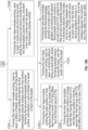
- FIG. 10A a flowchart shows a process of manufacturing the rotor 22.
- the method includes forming the rotor base 80 having the plurality of discrete sections 90 including a first section 100 that is adjacent to a diffuser shroud 24 when installed in the ACM 10.
- a second section 110 forms a seal 110 and is disposed against an aft frame member 52 of the ACM 10 when installed in the ACM 10.
- a third section 120 is connected to a compressor rotor shaft 54 when installed in the ACM 10.
- a fourth section 130 is connected to a tie rod 20 when installed in the ACM 10.
- a fifth section 140 is between the second section 110 and fourth section 130.
- Forming the rotor base 80 includes printing, layer by layer, the rotor base 80. This includes printing the first and second thermoplastic polymers surfaces 200, 210, respectively from first and second thermoplastic polymers, as separate surfaces that are disposed against each other.
- the first thermoplastic polymer surface 200 has a first coefficient of thermal expansion (CTE)
- the second thermoplastic polymer surface 210 has a second CTE.
- the method includes forming the lower support section 82 on the rotor base 80. This includes printing, layer by layer, along the plurality of discrete sections 90 of the rotor base 80, the mixture of the third thermoplastic polymer and the catalyst compound formed with metal.
- the method includes forming the upper support section 84 on the rotor 22. This includes depositing on the lower support section 82, along each of the discrete sections 90, via electrolysis deposition, the metallic coating. This configuration controls thermal expansion and contraction of the rotor 22 along the discrete sections 90.
- FIG. 10B shows additional aspects of block 110 of forming the rotor base 80.
- forming the rotor base 80 may include printing, layer by layer, the lattice of beads 245.
- Each of the beads 245 has the outer surface 202 formed by the first thermoplastic polymer surface 200 and the inner surface 212 formed by the second thermoplastic polymer surface 210.
- the void 220 is formed in the center of each of the beads 245.
- forming the rotor base 80 may include printing the outer surface 202 or inner surface 212 of each bead 245 to include the first fiber 300.
- the first fiber 300 has the fourth CTE that differs from the first and second CTEs.
- forming the rotor base 80 may include printing the outer surface 202 to include the first fiber 300 having the fourth CTE, and the inner surface 212 to include the second fiber 310 that that has the fifth CTE that differs from each of the other CTEs.
- forming the rotor base 80 may include printing, layer by layer, the reinforcing fibrous string 330 on each bead 245.
- the string 330 may extend linearly across the bead 245, over the center void 220 of the bead 245.
- forming the rotor base 80 may include printing the first thermoplastic polymer surface 200 to provide a first CTE gradient CTE( ⁇ 1), and printing the second thermoplastic polymer surface 210 to provide a second CTE gradient CTE( ⁇ 2).
- the first and second gradients may change in a thickness direction of the rotor base 80.
- the CTEs may be the same as each other at the interface 360 between the first and second thermoplastic polymer surface 210.
- the first and second gradients may change in a circumferential direction.
- the CTEs may differ from each other at the interface 360 between the first and second thermoplastic polymer surface 210.
- forming the rotor base 80 may include printing, layer by layer, a continuous structure 247 having voids 220.
- the continuous structure 247 may be formed by the first thermoplastic polymer surface 200.
- Each of the voids 220 may be lined with the second thermoplastic polymer surface 212.
Landscapes
- Engineering & Computer Science (AREA)
- Chemical & Material Sciences (AREA)
- Materials Engineering (AREA)
- Mechanical Engineering (AREA)
- Manufacturing & Machinery (AREA)
- General Engineering & Computer Science (AREA)
- Physics & Mathematics (AREA)
- Optics & Photonics (AREA)
- Architecture (AREA)
- Ceramic Engineering (AREA)
- Civil Engineering (AREA)
- Composite Materials (AREA)
- Structural Engineering (AREA)
- Laminated Bodies (AREA)
Abstract
A method of forming a rotor for an ACM, having steps of forming a base (80) having: a first section (100) adjacent to an ACM diffuser shroud (24) when installed; a second section (110) forming a seal disposed against an ACM aft frame member (53) when installed; a third section (120) connected to an ACM compressor rotor shaft (54) when installed; a fourth section (130) connected to an ACM tie rod (20) when installed; a fifth section (140) between the second and fourth sections, forming the base includes: printing thermoplastic polymer surfaces (200, 210) from thermoplastic polymers disposed against each other, the thermoplastic polymer surfaces having different CTEs; forming a lower support section (82) on the base by printing along the discrete sections a mixture of a third thermoplastic polymer and a catalyst formed with metal; and forming an upper support section (84) on the rotor by depositing on the lower support section along the discrete sections, via electrolysis deposition, a metallic coating.
Description
- The embodiments are directed to rotors for an air cycle machine (ACM) and more specifically to metal plated additively manufactured plastic ACM rotors with internal thermally adaptive structure.
- Rotors manufactured using exotic materials may be expensive and heavy. Rotors may be additively manufactured from plastic and coated with strengthening materials. However due to different coefficients of expansion, the different materials may separate or fail.
- Disclosed is a method of forming a rotor for an air cycle machine (ACM), the method comprising: forming a rotor base having a plurality of discrete sections including: a first section that is adjacent to a diffuser shroud when installed in the ACM; a second section that forms a seal and is disposed against an aft frame member when installed in the ACM; a third section that is connected to a compressor rotor shaft when installed in the ACM; a fourth section that is connected to a tie rod when installed in the ACM; a fifth section that is between the second section and the fourth section, wherein forming the rotor base includes: printing, layer by layer, the rotor base, by printing first and second thermoplastic polymer surfaces, respectively from first and second thermoplastic polymers, that are disposed against each other, the first thermoplastic polymer surface having a first coefficient of thermal expansion (CTE), and the second thermoplastic polymer surface having a second CTE; forming a lower support section on the rotor base by printing, layer by layer, along the plurality of discrete sections of the rotor base a mixture of a third thermoplastic polymer and a catalyst formed with metal; and forming an upper support section on the rotor by depositing on the lower support section, along each of the discrete sections, via electrolysis deposition, a metallic coating, to thereby control thermal expansion and contraction of the rotor along the discrete sections, to thereby make the rotor.
- In embodiments, the first and second CTEs differ from each other.
- In embodiments, forming the rotor base includes printing, layer by layer, a lattice of beads, wherein the each of the beads has an outer surface formed by the first thermoplastic polymer surface and an inner surface formed by the second thermoplastic polymer surface, and wherein a void is formed in a center of each of the beads.
- In embodiments, the outer surface has first thickness and the inner surface has a second thickness that is greater than the first thickness.
- In embodiments, forming the rotor base includes printing the outer surface or the inner surface of each bead to include a first fiber having a fourth CTE that differs from the first and second CTEs.
- In embodiments, forming the rotor base includes printing the outer surface to include the first fiber having the fourth CTE and the inner surface to include a second fiber that that has a fifth CTE that differs from each of the other CTEs.
- In embodiments, the CTEs, other than the fourth and fifth CTEs, are the same as each other.
- In embodiments, the first fiber and the second fiber differ from each other, each being one of metallic, carbon or Kevlar fibers.
- In embodiments, forming the rotor base includes printing, layer by layer, a reinforcing fibrous string on each bead, wherein the string extends linearly across the bead, over the void of the bead.
- In embodiments, forming the rotor base includes: printing the first thermoplastic polymer surface to provide a first CTE gradient; and printing the second thermoplastic polymer surface to provide a second CTE gradient.
- In embodiments, the first and second gradients change in a thickness direction of the rotor base, and at an interface between the first and second thermoplastic polymer surfaces, the CTEs are the same as each other; or the first and second gradients change in a circumferential direction, and at the interface between the first and second thermoplastic polymer surfaces, the CTEs differ from each other.
- In embodiments, forming the rotor base includes printing, layer by layer, a continuous structure having voids, where the continuous structure is formed by the first thermoplastic polymer surface, and each of the voids is lined with the second thermoplastic polymer surface.
- In embodiments, the first and second thermoplastic polymer surfaces are the same as each other.
- In embodiments, the first thermoplastic polymer surface is Acrylonitrile butadiene styrene (ABS).
- In embodiments, the catalyst is palladium(II) chloride (PdCl2).
- In embodiments, the method includes utilizing stereolithography (SLA) or fused deposition modeling (FDM).
- An air cycle machine of an aircraft is disclosed that includes a rotor manufactured from a method having one or more of the above aspects; the diffuser shroud that is adjacent to the first section of the rotor; the aft frame member that is adjacent to the seal formed along the second section of the rotor; the compressor rotor shaft connected to the third section of the rotor; and the tie rod that is connected to the fourth section of the rotor.
- The following descriptions should not be considered limiting in any way. With reference to the accompanying drawings, like elements are numbered alike:
-
FIG. 1 shows an air cycle machine (ACM) according to an embodiment; -
FIG. 2 shows a rotor of the ACM manufactured according to the embodiment; -
FIG. 3 shows additional aspects of the rotor, including locations of increased thermal stress; -
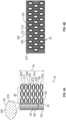
FIG. 4A shows aspects of the additively manufactured shroud base with a lattice of beads manufactured of multiple plastic extrusions or printings to enable controlling of thermal expansion of the shroud base; -
FIG. 4B shows aspects of the additively manufactured shroud base with a block manufactured of multiple plastic extrusions or printings to enable controlling of thermal expansion of the shroud; -
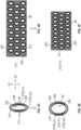
FIG. 4C shows a bead, with the two thermoplastic polymer surfaces having CTE gradients that are different from each other at their interface and each one changes in the hoop or circumferential direction, at a temperature T1;FIG. 4D shows the block at a temperature T1; -
FIG. 4E shows the bead ofFIG. 4C at a temperature T2>T1; -
FIG. 4F shows the block ofFIG. 4D at a temperature T2>T2; -
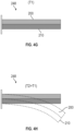
FIG. 4G shows an equivalent structure to the structures shown inFIGS. 4C-4F , with two thermoplastic polymer surfaces having different coefficients of thermal expansion (CTE), at a temperature T1; -
FIG. 4H shows the structure ofFIG. 4G at a temperature T2>T1; -
FIG. 5A shows an equivalent structure to the structures shown inFIGS. 4C-4F , with fibers in one of the two thermoplastic polymer surfaces, at a temperature T1; -
FIG. 5B shows the structure ofFIG. 5A at a temperature T2>T1; -
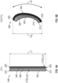
FIG. 6A shows an equivalent structure to the structures shown inFIGS. 4C-4F , with fibers in both of the thermoplastic polymer surfaces having different CTEs from each other, at a temperature T1; -
FIG. 6B shows the structure ofFIG. 6A at a temperature T2>T1; -
FIG. 7A shows a bead, with a fibrous string extending across the bead, at a temperature T1; -
FIG. 7B shows the structure ofFIG. 7A at a temperature T2>T1; -
FIG. 8A shows an equivalent structure to the structures shown inFIGS. 4C-4F , with the two thermoplastic polymer surfaces having CTE gradients with a common value at an interface of the thermoplastic polymer surfaces and having different values away from the interface, at a temperature T1; -
FIG. 8B shows the structure ofFIG. 8A at a temperature T2>T1; -
FIG. 9A shows beads of various shapes at a temperature T1; -
FIG. 9B shows the structures ofFIG. 9A at a temperature T2>T1; -
FIG. 10A is a flowchart showing a method of manufacturing a rotor according to the embodiments; and -
FIG. 10B is another flowchart showing the method of manufacturing a rotor according to the embodiments. - A detailed description of one or more embodiments of the disclosed apparatus and method are presented herein by way of exemplification and not limitation with reference to the Figures.
-
FIG. 1 shows an air cycle machine (ACM) 10 of an aircraft 5 (shown schematically). The ACM 10 may include anouter case 11 that has aninlet housing 12 of acompressor inlet 14, and a motorcooling supply port 16. Downstream of theinlet housing 12 is aFOD screen 18. Atie rod 20 is surrounded by acompressor rotor 22. A diffusor rotor shroud (or shroud) 24 and anadd heat housing 26 of theouter case 11 surround anadd heat supply 28. Theadd heat housing 26 is connected to theouter case 11 via aforward frame member 25. Exterior to the addheat housing 26 is abackup ring 30 supporting a drive ring bearing 32. The drive ring bearing 32 is structurally coupled to a drive ring 34 andpinion 35. The ACM 10 includes a diffuser vane 36 and avariable diffusor actuator 40. Downstream of thecompressor rotor 22 is aninboard plate 42 structurally coupled to abacking plate 44. Anoutlet housing 46 of theouter case 11 defines acompressor outlet 48. Thecompressor outlet 48 is secured with abolt ring 50 to anintermediate frame member 52 of theACM case 11. Arotor shaft 54 and aftthrust bearing shaft 56 are supported by journal bearings and asleeve 58. The journal bearing andsleeve 58 are supported by thecase 11 via, e.g., theintermediate frame member 52 and anaft frame member 53. Thetie rod 20 is supported over therotor shaft 54 by atie rod support 60. TheACM case 11 defines a bearing andmotor cooling outlet 62. Amotor cooling inlet 64 is defined at anaft motor housing 66. Surrounding thethrust shaft 56 are thrustbearings 68. Athrust plate 70 is located at the aft end of the ACM 10. The aft end of the ACM 10 also defines abearing cooling inlet 72 and includes lead wires and acover plate 74. Between themotor cooling inlet 64 andoutlet 62 is amotor stator 76 androtor 78. -
FIG. 2 shows therotor 22 of the ACM 10 that is additively manufactured according to the disclosed embodiments. The additive manufacturing process may utilize stereolithography (SLA) or fused deposition modeling (FDM) as non-limiting examples, e.g., utilizing a multi-head 3D printer.FIG. 3 shows additional aspects of therotor 22. Therotor 22 has abase 80, which forms the general shape of therotor 22. - The
rotor base 80 has certain discrete sections (generally 90), that experience thermal stress in operation, including afirst section 100 that is adjacent to adiffuser shroud 24 when installed in the ACM 10. Asecond section 110 forms aseal 110 and is disposed against anaft frame member 52 of the ACM 10 when installed in the ACM 10. Athird section 120 is connected to acompressor rotor shaft 54 when installed in the ACM 10. Afourth section 130 is connected to atie rod 20 when installed in the ACM 10. Afifth section 140 is between thesecond section 110 andfourth section 130. As shown inFIG. 3 , the only thefirst section 100 is on theblade portion 22a of therotor 22, and the remaining sections are on theroot 22b. - As will be discussed in greater detail below, the
rotor base 80 is manufactured of different thermoplastic polymers (plastics) having different coefficients of thermal expansion (CTE), and the discrete sections 90 are plated in metal. In a multi-head 3D printer, each print head could selectively print a different one of thermoplastic polymers and mixtures identified herein. Due to the utilization of the multiple plastics in therotor base 80, the metal plating does not separate when therotor 22 is subjected to thermal stress. - Turning to
FIG. 4A , therotor base 80 extends from abottom 150 of therotor 22 to a firstintermediate location 160 in a thickness direction. Alower support section 82 is disposed over therotor base 80 in the thickness direction. Thelower support section 82 is located along the discrete sections 90 but not the remainder of therotor base 80. Thelower support section 82 extends from the firstintermediate location 160 to a secondintermediate location 180. Anupper support section 84 is disposed over thelower support section 82. Theupper support section 84 is also located along the discrete sections 90 but not the remainder of therotor base 80. Theupper support section 84 extends from the secondintermediate location 180 to a top 190. The lower andupper support sections - The
rotor base 80 is formed by utilizing first and second thermoplastic polymers to respectively build up, layer by layer, first and second thermoplastic polymer surfaces 200, 210. That is, each of the first and second thermoplastic polymers surfaces 200, 210 is formed of one of the first and second thermoplastic polymers. The first and second thermoplastic polymers surfaces 200, 210 have differing CTEs. As disclosed in greater detail below, the first and second thermoplastic polymer surfaces 200, 210 are respectively configured as outer andinner surfaces void 220 is defined within theinner surface 212. - The
lower support section 82 is a mixture of athird plastic 230 and acatalyst 240 compound that includes metal. The catalyst may be is palladium(II) chloride (PdCl2). Theupper supper section 84 is a metal plating that is formed via electrolysis deposition so that the plating may be Pd. In one embodiment, the firstthermoplastic polymer surface 200 is acrylonitrile butadiene styrene (ABS). In one embodiment, the first and second thermoplastic polymer surfaces 200, 210 are the same as each other. In one embodiment, all of the utilized plastic in therotor 22 be the same thermoplastic polymer, such as ABS. - As shown in
FIG. 4A , the first and second thermoplastic polymer surfaces 200, 210 in therotor base 80 may be formed as lattice ofinterconnected beads 245 that have an oval shape. Thebeads 245 are micro-pattern elements. The firstthermoplastic polymer surface 200 may form theouter bead surface 202 and the secondthermoplastic polymer surface 210 may form theinner bead surface 212. Thevoid 220 is located in the center of eachbead 245. Theouter surface 202 has first thickness TH1 and theinner surface 212 has a second thickness TH2 that is greater than the first thickness TH1. - Alternatively, as shown in
FIG. 4B , the firstthermoplastic polymer surface 200 of therotor base 80 may form acontinuous block 247 as theouter surface 202. Theblock 247 is formed withvoids 220 that are lined with the secondthermoplastic polymer surface 210 as theinner surface 212. - The resulting configuration is capable of controlling thermal expansion and contraction of the
shroud 24 along the discrete sections 90. As shown inFIGS. 4C and 4D at temperatures T1, and inFIGS. 4E and 4F at temperatures T2>T1, theshroud base 80 has a controlled thermal explanation due to different CTEs and formation of the first and second thermoplastic polymer surfaces 200, 210 in theshroud base 80. More specifically, regardingFIG. 4C , thebead 245 is shown in which both the firstthermoplastic polymer surface 200 and secondthermoplastic polymer surface 210, i.e., the outer andinner surfaces thermoplastic polymer surface 200 has a first CTE gradient CTE(Δ1) and the secondthermoplastic polymer surface 210 has a second CTE gradient CTE(Δ2). The gradients are formed such that they are different from each other at theirinterface 360 and each one changes in the hoop or circumferential direction. When the temperature is increased from T1 to T2, the resulting controlled bend of theshroud base 80 is shown in FIG. 9E. As shown, the bead has an oval or elliptical shape with a long and a narrow axis A1, A2, and, at temperature T2, thebead 245 becomes compressed along its narrow axis A2 due to the controlled deformation. InFIGS. 4C and 4E , thebead 245 is formed with a gradient of thermal expansion inside of the first and second thermoplastic polymer surfaces 200, 210, i.e., the outer andinner surfaces - In one embodiment, the density of the
beads 245 or size of thevoids 220 in thebeads 245 or thecontinuous block 247 at one or more of the discrete sections 90 may be adjusted when printing thebase 20. This adjustment may change the density and thus thermal response characteristics of thebase 80. -
FIGS. 4G and 4H show anequivalent structure 248 to the structures shown inFIGS. 4C-4F . Specifically, the first and second thermoplastic polymer surfaces 200, 210 are at a temperature T1 inFIG. 4G , and T2 that is greater than T1 inFIG. 4H . The controlled thermal expansion shown inFIG. 4H results from the thermoplastic polymer surfaces being integrally connected. That is, the first and second thermoplastic polymer surfaces 200, 210 bend together in a predictable and controlled way. That is, the controlled thermal expansion of the first and second thermoplastic polymer surfaces 200, 210 in the disclose embodiments prevents the metal plating of theupper support section 84 from breaking off therotor 22. - Thus, the embodiments provide a
rotor 22 made of plastic, which results in a cost reduction compared with making therotor 22 from more exotic materials. Therotor 22 is abrasion resistant, and is not prone to static electric charging. Therotor 22 is designed for optimizing thermal deflections, to reduce induced stress and weight, and increase performance. Different thermal expansion characteristics may be obtained using two different thermoplastic polymers in the additive manufacturing process. Alternatively, as discussed below, the same material may be utilized with fillings such as metallic, carbon, or Kevlar fibers in the additive manufacturing process. -
FIG. 5A and 5B also show anequivalent structure 248 to the structures shown inFIGS. 4C-4F .First fibers 300 are embedded in the one of the first and second thermoplastic polymer surfaces 200 (or 210), i.e., in one of the outer andinner surfaces rotor base 80. Thefibers 300 may have a fourth CTE which may differ from the first and second CTEs of the first and second thermoplastic polymer surfaces 200, 210. -
FIG. 5A shows therotor base 80 at temperature T1.FIG. 5B shows the controlled bend of therotor base 80 when the temperature is increased from T1 to T2. As shown, at temperature T1, thestructure 248 has a length L1 and at temperature T2, thestructure 248 has a length L2 due to the controlled deformation. With increasing temperature, material volute increases. However, if the additively reinforcingfiber 300 has a lower CTE, the expansion is restricted. Having this reinforcement non-uniformly distributed, may result in the non-uniform expansion and thus curvature or curvature change in shape. Therefore, while an expanded length would otherwise increase to L2 where L2>L1, due to thefibers 300, the length projected on the x axis (vertical) increase only to (L2x< L1). The surface having the larger CTE, e.g., without thefibers 300, would elongate, resulting in a curative increase. -
FIGS. 6A and 6B show anotherequivalent structure 248 to the structures shown inFIGS. 4C-4F . Thefirst fibers 300 embedded in the firstthermoplastic polymer surface 200 i.e., theouter surface 202.Second fibers 310 are embedded in the secondthermoplastic polymer surface 210, i.e., theinner surface 212. Thesecond fibers 310 may have a fifth CTE which differs from each of the other CTEs. In one embodiment, the fourth and fifth CTEs differ from each other while the other CTEs are the same as each other. - When the temperature is increased from T1 to T2, the controlled bend of the
rotor base 80 is shown inFIG. 6B . As shown, at temperature T1, thestructure 248 has a length L1 and at temperature T2, thestructure 248 has a length L2x rather than a more expanded length L2 due to the controlled deformation. InFIGS. 6A and 6B , thestructure 248 has a variable composition with a gradient in the CTE that may be produced with a variation of the type of the reinforcingfiber fiber fibers inner surfaces - Turning to
FIG. 7A , thebead 245 is shown with afibrous string 330 that extends across thebead 245, over both thermoplastic polymer surfaces 200, 210, i.e., both of the outer andinner surfaces void 220. WhileFIG. 7A shows thebead 245 at temperature T1,FIG. 7B shows thebead 245 at temperature T2>T1. InFIG. 7B , thebead 245 displays a controlled change in shape due to the combination of material properties in the thermoplastic polymer surfaces 200, 210, i.e., the outer andinner surfaces fibrous string 330. The stiffness-increasing fibrous string may be additively manufactured with the rest of therotor base 80. -
FIGS. 8Aa and 8B show anequivalent structure 248 to the structures shown inFIGS. 4C-4F . Both the first and second thermoplastic polymer surfaces 200, 210, i.e., the outer andinner surfaces thermoplastic polymer surface 200 has a first CTE gradient CTE(Δ1) and the secondthermoplastic polymer surface 210 has a second CTE gradient CTE(Δ2). The gradients are formed such that they are different from each other at opposite ends 340, 350 of the structure (e.g., inside to outside) but are the same as each other at theirinterface 360. When the temperature is increased from T1 to T2, the controlled bend of thestructure 248 is shown inFIG. 8B . As shown, at temperature T1, thestructure 248 has a length L1 and at temperature T2, thestructure 248 has a length L2x rather than the more expanded length L2 due to the controlled deformation. InFIGS. 8A and 8B , the variable CTE may be produced by gradually changing from the first to the second thermoplastic polymer surfaces 200, 210, i.e., during printing, between the outer andinner surfaces - Turning to
FIGS. 9A and 9B , various shapes of thebeads 245 are within the scope of the embodiments, including oval 245A,diamond 245B and randomclosed loop 245C. Each is configured similar toFIG. 4C to provide for a deformation along a desired axis, for example, the narrow axis A2 rather than the long axis A1 when a temperature is increase from T1 (FIG. 9A ) to T2 (FIG. 9B ).. - Turning to
FIG. 10A a flowchart shows a process of manufacturing therotor 22. - As shown in
block 110 the method includes forming therotor base 80 having the plurality of discrete sections 90 including afirst section 100 that is adjacent to adiffuser shroud 24 when installed in the ACM 10. Asecond section 110 forms aseal 110 and is disposed against anaft frame member 52 of the ACM 10 when installed in the ACM 10. Athird section 120 is connected to acompressor rotor shaft 54 when installed in the ACM 10. Afourth section 130 is connected to atie rod 20 when installed in the ACM 10. Afifth section 140 is between thesecond section 110 andfourth section 130. - Forming the
rotor base 80 includes printing, layer by layer, therotor base 80. This includes printing the first and second thermoplastic polymers surfaces 200, 210, respectively from first and second thermoplastic polymers, as separate surfaces that are disposed against each other. The firstthermoplastic polymer surface 200 has a first coefficient of thermal expansion (CTE), and the secondthermoplastic polymer surface 210 has a second CTE. - As shown in
block 120, the method includes forming thelower support section 82 on therotor base 80. This includes printing, layer by layer, along the plurality of discrete sections 90 of therotor base 80, the mixture of the third thermoplastic polymer and the catalyst compound formed with metal. - As shown in
block 130, the method includes forming theupper support section 84 on therotor 22. This includes depositing on thelower support section 82, along each of the discrete sections 90, via electrolysis deposition, the metallic coating. This configuration controls thermal expansion and contraction of therotor 22 along the discrete sections 90. -
FIG. 10B shows additional aspects ofblock 110 of forming therotor base 80. As shown in block 110A1 (andFIG. 4A ), forming therotor base 80 may include printing, layer by layer, the lattice ofbeads 245. Each of thebeads 245 has theouter surface 202 formed by the firstthermoplastic polymer surface 200 and theinner surface 212 formed by the secondthermoplastic polymer surface 210. Thevoid 220 is formed in the center of each of thebeads 245. - As shown in block 110A2 (and
FIGS. 5A-5B ), forming therotor base 80 may include printing theouter surface 202 orinner surface 212 of eachbead 245 to include thefirst fiber 300. Thefirst fiber 300 has the fourth CTE that differs from the first and second CTEs. As shown in block 110A3 (andFIGS. 6A-6B ), forming therotor base 80 may include printing theouter surface 202 to include thefirst fiber 300 having the fourth CTE, and theinner surface 212 to include thesecond fiber 310 that that has the fifth CTE that differs from each of the other CTEs. - As shown in block 110A4 (and
FIGS. 7A-7B ), forming therotor base 80 may include printing, layer by layer, the reinforcingfibrous string 330 on eachbead 245. Thestring 330 may extend linearly across thebead 245, over thecenter void 220 of thebead 245. - As shown in block 110A5, forming the
rotor base 80 may include printing the firstthermoplastic polymer surface 200 to provide a first CTE gradient CTE(Δ1), and printing the secondthermoplastic polymer surface 210 to provide a second CTE gradient CTE(Δ2). As shown inFIGS. 8A-8B , the first and second gradients may change in a thickness direction of therotor base 80. The CTEs may be the same as each other at theinterface 360 between the first and secondthermoplastic polymer surface 210. As shown inFIGS. 9A-9B , the first and second gradients may change in a circumferential direction. The CTEs may differ from each other at theinterface 360 between the first and secondthermoplastic polymer surface 210. - As shown in block 110A6 (and
FIG. 4B ), forming therotor base 80 may include printing, layer by layer, acontinuous structure 247 havingvoids 220. Thecontinuous structure 247 may be formed by the firstthermoplastic polymer surface 200. Each of thevoids 220 may be lined with the secondthermoplastic polymer surface 212. - The terminology used herein is for the purpose of describing particular embodiments only and is not intended to be limiting of the present disclosure. As used herein, the singular forms "a", "an" and "the" are intended to include the plural forms as well, unless the context clearly indicates otherwise. It will be further understood that the terms "comprises" and/or "comprising," when used in this specification, specify the presence of stated features, integers, steps, operations, elements, and/or components, but do not preclude the presence or addition of one or more other features, integers, steps, operations, element components, and/or groups thereof.
- Those of skill in the art will appreciate that various example embodiments are shown and described herein, each having certain features in the particular embodiments, but the present invention can be modified to incorporate any number of variations, alterations, substitutions, combinations, sub-combinations, or equivalent arrangements not heretofore described, but which are within the scope of the invention as defined by the claims.
Claims (15)
- A method of forming a rotor for an air cycle machine, ACM, the method comprising:forming a rotor base (80) having a plurality of discrete sections including: a first section (100) that is adjacent to a diffuser shroud (24) when installed in the ACM; a second section (110) that forms a seal and is disposed against an aft frame member (53) when installed in the ACM; a third section (120) that is connected to a compressor rotor shaft (54) when installed in the ACM; a fourth section (130) that is connected to a tie rod (20) when installed in the ACM; a fifth section (140) that is between the second section and the fourth section,wherein forming the rotor base includes:printing, layer by layer, the rotor base, by printing first and second thermoplastic polymer surfaces (200, 210), respectively from first and second thermoplastic polymers, that are disposed against each other, the first thermoplastic polymer surface having a first coefficient of thermal expansion, CTE, and the second thermoplastic polymer surface having a second CTE;forming a lower support section (82) on the rotor base by printing, layer by layer, along the plurality of discrete sections of the rotor base a mixture of a third thermoplastic polymer and a catalyst formed with metal; andforming an upper support section (84) on the rotor by depositing on the lower support section, along each of the discrete sections, via electrolysis deposition, a metallic coating, to thereby control thermal expansion and contraction of the rotor along the discrete sections, to thereby make the rotor.
- The method of claim 1, wherein the first and second CTEs differ from each other.
- The method of claim 1 or 2, wherein:
forming the rotor base includes printing, layer by layer, a lattice of beads (245), wherein each of the beads has an outer surface (202) formed by the first thermoplastic polymer surface and an inner surface (212) formed by the second thermoplastic polymer surface, and wherein a void is formed in a center of each of the beads. - The method of claim 3, wherein:
the outer surface has first thickness and the inner surface has a second thickness that is greater than the first thickness. - The method of claim 4, wherein:
forming the rotor base includes printing the outer surface or the inner surface of each bead to include a first fiber having a fourth CTE that differs from the first and second CTEs. - The method of claim 5, wherein:
forming the rotor base includes printing the outer surface to include the first fiber having the fourth CTE and the inner surface to include a second fiber that that has a fifth CTE that differs from each of the other CTEs. - The method of claim 6, wherein the CTEs, other than the fourth and fifth CTEs, are the same as each other, or wherein the first fiber and the second fiber differ from each other, each being one of metallic, carbon or Kevlar fibers.
- The method of claim 3, wherein:
forming the rotor base includes printing, layer by layer, a reinforcing fibrous string (330) on each bead, wherein the string extends linearly across the bead, over the void of the bead. - The method of claim 3, wherein forming the rotor base includes:printing the first thermoplastic polymer surface to provide a first CTE gradient; andprinting the second thermoplastic polymer surface to provide a second CTE gradient; and optionally wherein:the first and second gradients change in a thickness direction of the rotor base, and at an interface between the first and second thermoplastic polymer surfaces, the CTEs are the same as each other; orthe first and second gradients change in a circumferential direction, and at the interface between the first and second thermoplastic polymer surfaces, the CTEs differ from each other.
- The method of claim 1, wherein:
forming the rotor base includes printing, layer by layer, a continuous structure having voids, where the continuous structure is formed by the first thermoplastic polymer surface, and each of the voids is lined with the second thermoplastic polymer surface. - The method of any preceding claim, wherein the first and second thermoplastic polymer surfaces are the same as each other.
- The method of any preceding claim, wherein the first thermoplastic polymer surface is Acrylonitrile butadiene styrene, ABS.
- The method of any preceding claim, wherein the catalyst is palladium(II) chloride (PdCl2).
- The method of any preceding claim, including utilizing stereolithography, SLA, or fused deposition modeling, FDM.
- An air cycle machine of an aircraft, comprising:a rotor (22) manufactured from the method of any preceding claim;the diffuser shroud (24) that is adjacent to the first section of the rotor;the aft frame member (53) that is adjacent to the seal formed along the second section of the rotor;the compressor rotor shaft (54) connected to the third section of the rotor; andthe tie rod (20) that is connected to the fourth section of the rotor.
Applications Claiming Priority (1)
| Application Number | Priority Date | Filing Date | Title |
|---|---|---|---|
| US18/357,571 US20250033270A1 (en) | 2023-07-24 | 2023-07-24 | Metal plated additively manufactured plastic acm rotors with internal thermally adaptive structure |
Publications (1)
| Publication Number | Publication Date |
|---|---|
| EP4506150A1 true EP4506150A1 (en) | 2025-02-12 |
Family
ID=91969022
Family Applications (1)
| Application Number | Title | Priority Date | Filing Date |
|---|---|---|---|
| EP24190738.5A Pending EP4506150A1 (en) | 2023-07-24 | 2024-07-24 | Metal plated additively manufactured plastic acm rotors with internal thermally adaptive structure |
Country Status (2)
| Country | Link |
|---|---|
| US (1) | US20250033270A1 (en) |
| EP (1) | EP4506150A1 (en) |
Families Citing this family (1)
| Publication number | Priority date | Publication date | Assignee | Title |
|---|---|---|---|---|
| US12384515B2 (en) | 2023-09-08 | 2025-08-12 | Hamilton Sundstrand Corporation | Airfoil formed of thermally adaptive materials and a thermoelectric junction |
Citations (3)
| Publication number | Priority date | Publication date | Assignee | Title |
|---|---|---|---|---|
| WO2015006438A1 (en) * | 2013-07-09 | 2015-01-15 | United Technologies Corporation | Plated polymer compressor |
| EP4209681A1 (en) * | 2022-01-07 | 2023-07-12 | Hamilton Sundstrand Corporation | Rotor formed of multiple metals |
| EP4411108A2 (en) * | 2023-02-01 | 2024-08-07 | Hamilton Sundstrand Corporation | Metal plated additively manufactured plastic rotors and their method of manufacturing |
-
2023
- 2023-07-24 US US18/357,571 patent/US20250033270A1/en active Pending
-
2024
- 2024-07-24 EP EP24190738.5A patent/EP4506150A1/en active Pending
Patent Citations (3)
| Publication number | Priority date | Publication date | Assignee | Title |
|---|---|---|---|---|
| WO2015006438A1 (en) * | 2013-07-09 | 2015-01-15 | United Technologies Corporation | Plated polymer compressor |
| EP4209681A1 (en) * | 2022-01-07 | 2023-07-12 | Hamilton Sundstrand Corporation | Rotor formed of multiple metals |
| EP4411108A2 (en) * | 2023-02-01 | 2024-08-07 | Hamilton Sundstrand Corporation | Metal plated additively manufactured plastic rotors and their method of manufacturing |
Also Published As
| Publication number | Publication date |
|---|---|
| US20250033270A1 (en) | 2025-01-30 |
Similar Documents
| Publication | Publication Date | Title |
|---|---|---|
| EP4497569B1 (en) | Metal plated additively manufactured plastic acm housings with internal thermally adaptive structure | |
| EP4497570A1 (en) | Metal plated additively manufactured plastic acm shrouds with internal thermally adaptive structure | |
| EP4497568A1 (en) | Method for forming a shaft for an air cycle machine | |
| CN112739530B (en) | Composite shell with integrated reinforcement | |
| JP7618906B2 (en) | Enhanced Vacuum System Components | |
| EP4497521A1 (en) | Metal plated additively manufactured plastic acm seal plates with internal thermally adaptive structure | |
| CN103261499B (en) | Fibrous structure for a part made of composite material having one or more arch-shaped portions | |
| US20250033270A1 (en) | Metal plated additively manufactured plastic acm rotors with internal thermally adaptive structure | |
| JP2015525150A (en) | Aircraft engine auxiliary structures and processes related to auxiliary structures | |
| US9492970B2 (en) | Method for manufacturing the impeller of a centrifugal compressor | |
| EP4411108B1 (en) | Metal plated additively manufactured plastic rotors and their method of manufacturing | |
| EP4520529A1 (en) | Metal plated plastic acm part with internal thermally adaptive structure | |
| CN109458362B (en) | Reinforced shape composite material shell | |
| US11890822B2 (en) | Component of revolution made of composite material having improved resistance to delamination | |
| US8075719B2 (en) | Manufacture of complex composite parts | |
| US11511372B2 (en) | Technique to improve the performance of a pump with a trimmed impeller using additive manufacturing | |
| CN101648176A (en) | Slit coating head | |
| US20250033796A1 (en) | Metal plating retention on additively manufacture plastic parts for an aircraft | |
| US20240401482A1 (en) | Composite Airfoil Assembly for a Turbine Engine | |
| US12359570B2 (en) | Composite airfoil assembly for a turbine engine | |
| EP4411107A2 (en) | Metal plated additively manufactured plastic shafts and their method of manufacturing | |
| EP3660279B1 (en) | Variable area fan nozzle with wall thickness distribution | |
| EP4411110A2 (en) | Metal plated additively manufactured plastic rotor shrouds and their method of manufacturing | |
| CN108602289B (en) | Prepreg manufacturing apparatus and prepreg manufacturing method using same |
Legal Events
| Date | Code | Title | Description |
|---|---|---|---|
| PUAI | Public reference made under article 153(3) epc to a published international application that has entered the european phase |
Free format text: ORIGINAL CODE: 0009012 |
|
| STAA | Information on the status of an ep patent application or granted ep patent |
Free format text: STATUS: THE APPLICATION HAS BEEN PUBLISHED |
|
| AK | Designated contracting states |
Kind code of ref document: A1 Designated state(s): AL AT BE BG CH CY CZ DE DK EE ES FI FR GB GR HR HU IE IS IT LI LT LU LV MC ME MK MT NL NO PL PT RO RS SE SI SK SM TR |
|
| STAA | Information on the status of an ep patent application or granted ep patent |
Free format text: STATUS: REQUEST FOR EXAMINATION WAS MADE |
|
| 17P | Request for examination filed |
Effective date: 20250812 |