EP4506086A2 - Dual-material components and methods of making therefor - Google Patents
Dual-material components and methods of making therefor Download PDFInfo
- Publication number
- EP4506086A2 EP4506086A2 EP24193391.0A EP24193391A EP4506086A2 EP 4506086 A2 EP4506086 A2 EP 4506086A2 EP 24193391 A EP24193391 A EP 24193391A EP 4506086 A2 EP4506086 A2 EP 4506086A2
- Authority
- EP
- European Patent Office
- Prior art keywords
- component
- assembly
- dual
- base plate
- base
- Prior art date
- Legal status (The legal status is an assumption and is not a legal conclusion. Google has not performed a legal analysis and makes no representation as to the accuracy of the status listed.)
- Pending
Links
Images


Classifications
-
- B—PERFORMING OPERATIONS; TRANSPORTING
- B22—CASTING; POWDER METALLURGY
- B22F—WORKING METALLIC POWDER; MANUFACTURE OF ARTICLES FROM METALLIC POWDER; MAKING METALLIC POWDER; APPARATUS OR DEVICES SPECIALLY ADAPTED FOR METALLIC POWDER
- B22F10/00—Additive manufacturing of workpieces or articles from metallic powder
- B22F10/20—Direct sintering or melting
- B22F10/28—Powder bed fusion, e.g. selective laser melting [SLM] or electron beam melting [EBM]
-
- B—PERFORMING OPERATIONS; TRANSPORTING
- B22—CASTING; POWDER METALLURGY
- B22F—WORKING METALLIC POWDER; MANUFACTURE OF ARTICLES FROM METALLIC POWDER; MAKING METALLIC POWDER; APPARATUS OR DEVICES SPECIALLY ADAPTED FOR METALLIC POWDER
- B22F10/00—Additive manufacturing of workpieces or articles from metallic powder
- B22F10/20—Direct sintering or melting
- B22F10/25—Direct deposition of metal particles, e.g. direct metal deposition [DMD] or laser engineered net shaping [LENS]
-
- B—PERFORMING OPERATIONS; TRANSPORTING
- B22—CASTING; POWDER METALLURGY
- B22F—WORKING METALLIC POWDER; MANUFACTURE OF ARTICLES FROM METALLIC POWDER; MAKING METALLIC POWDER; APPARATUS OR DEVICES SPECIALLY ADAPTED FOR METALLIC POWDER
- B22F10/00—Additive manufacturing of workpieces or articles from metallic powder
- B22F10/60—Treatment of workpieces or articles after build-up
- B22F10/64—Treatment of workpieces or articles after build-up by thermal means
-
- B—PERFORMING OPERATIONS; TRANSPORTING
- B22—CASTING; POWDER METALLURGY
- B22F—WORKING METALLIC POWDER; MANUFACTURE OF ARTICLES FROM METALLIC POWDER; MAKING METALLIC POWDER; APPARATUS OR DEVICES SPECIALLY ADAPTED FOR METALLIC POWDER
- B22F12/00—Apparatus or devices specially adapted for additive manufacturing; Auxiliary means for additive manufacturing; Combinations of additive manufacturing apparatus or devices with other processing apparatus or devices
- B22F12/30—Platforms or substrates
-
- B—PERFORMING OPERATIONS; TRANSPORTING
- B22—CASTING; POWDER METALLURGY
- B22F—WORKING METALLIC POWDER; MANUFACTURE OF ARTICLES FROM METALLIC POWDER; MAKING METALLIC POWDER; APPARATUS OR DEVICES SPECIALLY ADAPTED FOR METALLIC POWDER
- B22F7/00—Manufacture of composite layers, workpieces, or articles, comprising metallic powder, by sintering the powder, with or without compacting wherein at least one part is obtained by sintering or compression
- B22F7/06—Manufacture of composite layers, workpieces, or articles, comprising metallic powder, by sintering the powder, with or without compacting wherein at least one part is obtained by sintering or compression of composite workpieces or articles from parts, e.g. to form tipped tools
- B22F7/08—Manufacture of composite layers, workpieces, or articles, comprising metallic powder, by sintering the powder, with or without compacting wherein at least one part is obtained by sintering or compression of composite workpieces or articles from parts, e.g. to form tipped tools with one or more parts not made from powder
-
- B—PERFORMING OPERATIONS; TRANSPORTING
- B23—MACHINE TOOLS; METAL-WORKING NOT OTHERWISE PROVIDED FOR
- B23K—SOLDERING OR UNSOLDERING; WELDING; CLADDING OR PLATING BY SOLDERING OR WELDING; CUTTING BY APPLYING HEAT LOCALLY, e.g. FLAME CUTTING; WORKING BY LASER BEAM
- B23K15/00—Electron-beam welding or cutting
- B23K15/0046—Welding
- B23K15/0086—Welding welding for purposes other than joining, e.g. build-up welding
-
- B—PERFORMING OPERATIONS; TRANSPORTING
- B23—MACHINE TOOLS; METAL-WORKING NOT OTHERWISE PROVIDED FOR
- B23K—SOLDERING OR UNSOLDERING; WELDING; CLADDING OR PLATING BY SOLDERING OR WELDING; CUTTING BY APPLYING HEAT LOCALLY, e.g. FLAME CUTTING; WORKING BY LASER BEAM
- B23K26/00—Working by laser beam, e.g. welding, cutting or boring
- B23K26/34—Laser welding for purposes other than joining
- B23K26/342—Build-up welding
-
- B—PERFORMING OPERATIONS; TRANSPORTING
- B33—ADDITIVE MANUFACTURING TECHNOLOGY
- B33Y—ADDITIVE MANUFACTURING, i.e. MANUFACTURING OF THREE-DIMENSIONAL [3D] OBJECTS BY ADDITIVE DEPOSITION, ADDITIVE AGGLOMERATION OR ADDITIVE LAYERING, e.g. BY 3D PRINTING, STEREOLITHOGRAPHY OR SELECTIVE LASER SINTERING
- B33Y10/00—Processes of additive manufacturing
-
- B—PERFORMING OPERATIONS; TRANSPORTING
- B33—ADDITIVE MANUFACTURING TECHNOLOGY
- B33Y—ADDITIVE MANUFACTURING, i.e. MANUFACTURING OF THREE-DIMENSIONAL [3D] OBJECTS BY ADDITIVE DEPOSITION, ADDITIVE AGGLOMERATION OR ADDITIVE LAYERING, e.g. BY 3D PRINTING, STEREOLITHOGRAPHY OR SELECTIVE LASER SINTERING
- B33Y40/00—Auxiliary operations or equipment, e.g. for material handling
- B33Y40/20—Post-treatment, e.g. curing, coating or polishing
-
- B—PERFORMING OPERATIONS; TRANSPORTING
- B33—ADDITIVE MANUFACTURING TECHNOLOGY
- B33Y—ADDITIVE MANUFACTURING, i.e. MANUFACTURING OF THREE-DIMENSIONAL [3D] OBJECTS BY ADDITIVE DEPOSITION, ADDITIVE AGGLOMERATION OR ADDITIVE LAYERING, e.g. BY 3D PRINTING, STEREOLITHOGRAPHY OR SELECTIVE LASER SINTERING
- B33Y70/00—Materials specially adapted for additive manufacturing
-
- B—PERFORMING OPERATIONS; TRANSPORTING
- B33—ADDITIVE MANUFACTURING TECHNOLOGY
- B33Y—ADDITIVE MANUFACTURING, i.e. MANUFACTURING OF THREE-DIMENSIONAL [3D] OBJECTS BY ADDITIVE DEPOSITION, ADDITIVE AGGLOMERATION OR ADDITIVE LAYERING, e.g. BY 3D PRINTING, STEREOLITHOGRAPHY OR SELECTIVE LASER SINTERING
- B33Y80/00—Products made by additive manufacturing
-
- B—PERFORMING OPERATIONS; TRANSPORTING
- B22—CASTING; POWDER METALLURGY
- B22F—WORKING METALLIC POWDER; MANUFACTURE OF ARTICLES FROM METALLIC POWDER; MAKING METALLIC POWDER; APPARATUS OR DEVICES SPECIALLY ADAPTED FOR METALLIC POWDER
- B22F2301/00—Metallic composition of the powder or its coating
- B22F2301/15—Nickel or cobalt
-
- B—PERFORMING OPERATIONS; TRANSPORTING
- B22—CASTING; POWDER METALLURGY
- B22F—WORKING METALLIC POWDER; MANUFACTURE OF ARTICLES FROM METALLIC POWDER; MAKING METALLIC POWDER; APPARATUS OR DEVICES SPECIALLY ADAPTED FOR METALLIC POWDER
- B22F7/00—Manufacture of composite layers, workpieces, or articles, comprising metallic powder, by sintering the powder, with or without compacting wherein at least one part is obtained by sintering or compression
- B22F7/06—Manufacture of composite layers, workpieces, or articles, comprising metallic powder, by sintering the powder, with or without compacting wherein at least one part is obtained by sintering or compression of composite workpieces or articles from parts, e.g. to form tipped tools
- B22F7/062—Manufacture of composite layers, workpieces, or articles, comprising metallic powder, by sintering the powder, with or without compacting wherein at least one part is obtained by sintering or compression of composite workpieces or articles from parts, e.g. to form tipped tools involving the connection or repairing of preformed parts
-
- Y—GENERAL TAGGING OF NEW TECHNOLOGICAL DEVELOPMENTS; GENERAL TAGGING OF CROSS-SECTIONAL TECHNOLOGIES SPANNING OVER SEVERAL SECTIONS OF THE IPC; TECHNICAL SUBJECTS COVERED BY FORMER USPC CROSS-REFERENCE ART COLLECTIONS [XRACs] AND DIGESTS
- Y02—TECHNOLOGIES OR APPLICATIONS FOR MITIGATION OR ADAPTATION AGAINST CLIMATE CHANGE
- Y02P—CLIMATE CHANGE MITIGATION TECHNOLOGIES IN THE PRODUCTION OR PROCESSING OF GOODS
- Y02P10/00—Technologies related to metal processing
- Y02P10/25—Process efficiency
Definitions
- the present disclosure relates to dual-material components and methods of making dual-material components.
- Material selection is very important for design performance of certain components. Whether required for thermal management, structural robustness, or corrosive resistance, using the best material is imperative. This can, however, cause difficulties when trying to join components of dissimilar metals into assemblies, especially when one metal joining technique is preferred. In certain applications, for example, it is greatly beneficial for a component to be of a material well-suited for a given purpose, but due to build parameters in the larger assembly, that material may not be well-suited for joining to the assembly because dissimilar metals can create a tricky and inconsistent quality of weld.
- a method includes additively manufacturing a component from a first material onto a baseplate manufactured of a second material to form a dual-material component for use in an assembly.
- the first material can be configured to manage heat within the assembly and the second material can be configured to form a weld j oint between the base plate of the dual-material component and the assembly for joining the dual-material component to the assembly.
- the method can further include machining the base plate to a predetermined geometry corresponding to a component seat within the assembly.
- the method can further include, installing the dual-material component into the component seat of the assembly, and welding the base plate of the dual-material component to the assembly at the weld interface to form a weld j oint to secure the dual-material component to the assembly.
- the method can include manufacturing the base plate from the second material.
- the method can also include manufacturing a build plate configured to hold one or more base plates and installing the one or more base plates into the build plate.
- manufacturing the build plate can further include forming a plurality of base plate recesses in the build plate and forming a respective build plate bore in each base plate recess of the plurality of base plate recesses.
- manufacturing the base plate can further include forming a respective base plate bore in each base plate.
- the one or more base plates can include a plurality of base plates, and installing the plurality of base plates into the build plate can include, placing a respective base plate into a respective base plate recess, and securing each respective base plate to the build plate in the respective base plate recess with a respective fastener extending through the respective base plate bore and into the respective build plate bore.
- the method can include additively manufacturing a plurality of components of the first material onto each to the respective base plates to manufacture a plurality of dual-material components on the same build plate.
- the first material can be different from the second material, and the second material can be the same as a material of the assembly at the weld interface. In embodiments, the first material can have a higher thermal conductivity than the second material. In certain embodiments, the first material can be nickel, the second material can be stainless steel, and the material of the assembly at the weld interface can be stainless steel.
- a method can include additively manufacturing a component from a first material, and cladding a base portion of a second material onto the component to form a dual-material component for use in an assembly.
- the first material can be configured to manage heat within the assembly and the second material can be configured to form a weld joint between the base portion of the component and the assembly for joining the component to the assembly.
- cladding the base portion onto the component can include applying with a cladding nozzle, the second material to the first material to grow the base portion from the component to manufacture the dual-material component.
- the method can further include, machining the base portion to a predetermined geometry corresponding to a component seat within the assembly.
- the method can include, installing the component into the component seat of the assembly, and welding the base plate of the component to the assembly at the weld interface to form a weld j oint to secure the component to the assembly.
- the first material can be different from the second material, and the second material can be different than a material of the assembly at the weld interface and configured to form a compatible alloy system at the weld interface.
- the first material can have a higher thermal conductivity than the second material.
- the first material can be nickel
- the second material can be Inconel
- the material of the assembly at the weld interface can be stainless steel.
- a system can include, a housing assembly and an element assembly having a dual-material component therein, the element assembly joined within the housing assembly via a weld joint at a weld interface between the dual material component and the housing assembly.
- the dual-material component can include an additively manufactured component portion and a base portion, wherein the additively manufactured component portion is additively manufactured of a first material configured to manage heat within the housing assembly, and wherein the base portion is manufactured of a second material, different than the first material and compatible for welding with a material of the housing assembly.
- the first material can have a higher thermal conductivity than the second material.
- the additively manufactured component portion can be of nickel, the base portion can be of stainless steel, and wherein the housing assembly can be of stainless steel.
- the additively manufactured component portion can be of nickel, the base portion can be of Inconel, and the housing assembly can be of stainless steel.
- FIG. 1 an illustrative view of an embodiment of a system in accordance with the disclosure is shown in Fig. 1 and is designated generally by reference character 100.
- FIG. 2-15 Other embodiments and/or aspects of this disclosure are shown in Figs. 2-15 .
- a system 100 can include, a housing assembly 102 and an element assembly 104.
- the element assembly 104 can include a dual-material component 200, 300 therein.
- the element assembly 104 can be joined to and within the housing assembly 102 via a weld joint 106 at a weld interface 108 between the dual-material component 200, 300 and the housing assembly 102.
- the system 100 can also include a base assembly 110, where the base assembly 110 is installed to the housing assembly 102 after the element assembly 104 is welded to the housing assembly 102 via the dual-material component 200, 300.
- the dual-material component can include an additively manufactured component portion 212, 312 and a base portion 214, 314, wherein the additively manufactured component portion 212, 312 is additively manufactured from a first material configured to manage heat within the housing assembly 102, and the base portion 214, 314 is manufactured from a second material, different than the first material.
- the second material can be a material compatible for welding with a material of the housing assembly 102.
- the first material may not be compatible for welding with the material of the housing assembly 102.
- the component portion 212, 312 may require certain metal properties of a material that is not necessarily compatible with the housing assembly 102. Therefore, the dual-material component 200, 300 can have the base portion 214, 314 be of a material compatible for welding with the housing assembly 102 to ensure both the component portion 212, 312 provides is desired properties but that the component 200, 300 as a whole can still be securely installed into the housing assembly 102.
- the metallic properties of the first and second materials can include, among other things: the first material can have a higher thermal conductivity than the second material. Material properties may also be selected to promote welding and brazing between components or transitioning between varying coefficients of thermal expansion.
- the dual-material component 200 can be a nickel-stainless steel component, where the additively manufactured component portion 212 is of nickel (e.g., nickel 200) and the base portion 214 is of stainless steel such that the base portion 214 provides a similar metal for welding to the housing assembly 102, which is of stainless steel, in embodiments.
- a method 400 of manufacturing the component 200 is described herein with respect to Figs. 4-11 .
- the dual-material component 300 can be a nickel-Inconel component, where the additively manufactured component portion 312 is of nickel (e.g., nickel 200) and the base portion 314 is of Inconel (e.g., Inconel 625), such that the base portion 214 provides a compatible metal for welding to the housing assembly 102, which is of stainless steel, in embodiments.
- the two dissimilar metals of stainless steel and Inconel 625 can be suitable for forming a compatible allow system at the weld interface.
- a method 500 of manufacturing the component 300 is described herein with respect to Figs. 12-15 .
- a method 400 of making a dual-material component includes, additively manufacturing 416 the component portion 212 from the first material onto a baseplate (e.g., the base portion 214) manufactured from the second material.
- Additive manufacturing 416 can include additively manufacturing using an energy source 418 to fuse metallic powder on a powder bed (e.g., laser powder bed fusion as shown in Fig. 4 .), or powder or wire ejected from a nozzle 420 with an energy beam 422 from the energy source (e.g., directed energy deposition shown in Fig. 12 .). Any suitable additive manufacturing technique is contemplated herein as would be appreciated by those having ordinary skill in the art in view of this disclosure.
- the method 400 can further include machining 424 the base plate 214 to a predetermined geometry 426 corresponding to a component seat 428 within the housing assembly 102 (the component seat shown in Fig. 7 within a sensor base plate 431). After machining 424, the component 200 can take the form shown in Fig. 6 , where the diameter of the baseplate 214 matches a diameter of the component portion 212.
- the method 400 can further include, as shown in Fig.
- the method 400 can include separately manufacturing the base plate 214 from the second material, e.g., prior to additively manufacturing 416 the component portion 212 to the base plate 214.
- the method 400 can include producing a plurality of components 200 at the same time.
- the method 400 can also include manufacturing 432 a build plate 434 configured to hold one or more base plates 214 and installing the one or more base plates 214 into the build plate 434.
- manufacturing 432 the build plate can further include forming 436 a plurality of base plate recesses 438 in the build plate 434 and forming 440 a respective build plate bore 442 in each base plate recess 438 of the plurality of base plate recesses 438.
- manufacturing the base plate 214 can further include forming a respective base plate bore 444 in each base plate 214.
- the one or more base plates 214 can include a plurality of base plates 214
- the method 400 can further include installing 446 the plurality of base plates 214 into the build plate 434 can include, placing a respective base plate 214 into a respective base plate recess 438, and securing each respective base plate 214 to the build plate 434 in the respective base plate recess 438 with a respective fastener 448 extending through the respective base plate bore 444 and into the respective build plate bore 442.
- the method 400 can include additively manufacturing a plurality of components 200 of the first material onto each of the respective base plates 214 to manufacture a plurality of dual-material components 200 on the same build plate 434.
- a method 500 of manufacturing a dual-material component can include, additively manufacturing 516 the component portion 312 from a first material.
- Additive manufacturing 516 can be similar to additive manufacture 416, but additive manufacturing 516 can be remote to the rest of the method 500 and the component portion 312 can be manufactured on a conventional build plate, for example.
- the method 500 further includes cladding/directed energy deposition 550 the base portion 314 onto the component portion 312 to form the dual-material component 300 for use in the housing assembly 102.
- cladding 550 the base portion 314 onto the component portion 312 can include applying with a cladding nozzle 552, the second material to the component portion 312 to grow the base portion 314 from the component portion 312 to manufacture the dual-material component 300.
- the method 500 can further include, as shown in Fig. 13 , machining 524 the base portion 314 to a predetermined geometry 526 corresponding to a component seat 528 within the housing assembly 102 (the component seat shown in Fig. 15 within a sensor base plate 531). After machining 524, the component 300 can take the form shown in Fig. 14 , where the diameter of the baseplate 314 matches a diameter of the component portion 312.
- the method 500 can include, installing 529 the component 300 into the component seat 538 of the housing assembly 102, and welding 530 the base plate 314 of the component 300 to the housing assembly 102 at the weld interface 106 to form the weld joint 108 to secure the component 300 to the assembly 102.
- Nickel 200 has proven to provide superior thermal management properties for given applications, for example in air data sensing systems. However that same nickel 200 component (e.g., component 200, 300) needs to be laser welded to another stainless steel component (e.g., in the housing assembly 102). Nickel 200 and stainless steel are dissimilar metals that create a tricky weld which can be susceptible to hot cracking.
- the dual material component 200, 300 however, provides one material for thermal management (e.g., in the component portion 212, 312) and one for weldability (e.g., the base portion 214, 314), overcoming the noted challenges.
- methods 400 and 500 can use additive manufacturing to create a dual material component 200, 300 with a material transition to stainless steel or Inconel at the weld interface (e.g., a weld flange) creating a component with the required thermal management qualities and a robust and consistent weld.
- the material of the component could be nickel and the weld interface (e.g., base portion 214, 314) could be stainless steel or Inconel. Both are described herein.
- the dual material component 200 can be created using a stainless steel base material was attached to an additive manufacturing build plate. Then a nickel 200 component can be grown on top of the stainless steel base material. Next, the excess base material can be machined away creating the dual material component 200. This process is shown in Figs. 4-7 .
- This component 200 can have all the thermal properties required to perform well in heat and has a weld flange (e.g., base portion 214) of similar metals so it can be assembled easily and of high quality. The best quality weld would be stainless-steel to stainless-steel, thus in this embodiment, the base portion weld flange can be stainless steel.
- the nickel portion 212 of the component 200 is built in an inert environment and using a very precise set of laser welds. This produces a high quality weld with improved weld adhesion to the stainless steel build plate.
- nickel 200 component portion is able to be built onto the stainless steel base plate and allows provides for the similar metals (stainless to stainless) during the more difficult weld of welding the component 200 to the assembly.
- special build plates e.g., build plate 434
- stainless steel blanks e.g., base plates 2114
- Each potting well can be printed onto a blank which will limit the amount of wasted blank material and make post process machining easier and more consistent. This streamlined process is shown in Figs. 8-11 .
- the dual material component 300 can be created using am Inconel base material to for the weld flange so that the laser weld would be Inconel to stainless-steel when the component 300 is installed into the assembly 102.
- the method 500 for creating the component 300 using Inconel cladding can include first creating the main body of the component without the weld interface using any suitable method (e.g., additive manufacturing, casting). Next, Inconel material can be clad onto the main body and any excess cladded Inconel can be machined away. This can thus create the dual material potting well 300 that is of nickel 200 with an Inconel weld interface. This process is shown in Fig. 12-15 .
- dual material components 200, 300 can be produced having materials that maximize design performance while also producing high quality and repeatable weld interfaces. This can improve overall quality and minimize scrap while also reducing the difficulty of manufacturing.
- Embodiments include nickel 200 for the component portion 213, 312, as it has good thermal conductivity, anti-corrosion properties, it can be welded to Inconel 625 (which, in embodiments, is what the flow duct (the structure surrounding the potting well) is made from. Nickel 200 can also be additively manufactured, which is advantageous for manufacturing the complex design of the component portion 212, 312. Stainless steel and Inconel 625 can produce a very robust and repeatable laser beam weld between those two materials and the sensor baseplate 431, 531). A very high quality weld is required for that joint as it acts as a hermetic seal.
- a reference to "A and/or B", when used in conjunction with open-ended language such as “comprising” can refer, in one embodiment, to A only (optionally including elements other than B); in another embodiment, to B only (optionally including elements other than A); in yet another embodiment, to both A and B (optionally including other elements); etc.
Landscapes
- Engineering & Computer Science (AREA)
- Chemical & Material Sciences (AREA)
- Manufacturing & Machinery (AREA)
- Materials Engineering (AREA)
- Physics & Mathematics (AREA)
- Plasma & Fusion (AREA)
- Mechanical Engineering (AREA)
- Optics & Photonics (AREA)
- Thermal Sciences (AREA)
- Composite Materials (AREA)
- Laser Beam Processing (AREA)
- Connection Of Plates (AREA)
Abstract
Description
- The present disclosure relates to dual-material components and methods of making dual-material components.
- Material selection is very important for design performance of certain components. Whether required for thermal management, structural robustness, or corrosive resistance, using the best material is imperative. This can, however, cause difficulties when trying to join components of dissimilar metals into assemblies, especially when one metal joining technique is preferred. In certain applications, for example, it is greatly beneficial for a component to be of a material well-suited for a given purpose, but due to build parameters in the larger assembly, that material may not be well-suited for joining to the assembly because dissimilar metals can create a tricky and inconsistent quality of weld.
- The conventional techniques have been considered satisfactory for their intended purpose. However, there is an ever present need for improved systems and methods for making components that address the above noted concerns. This disclosure provides a solution for this need.
- In accordance with at least one aspect of this disclosure, a method includes additively manufacturing a component from a first material onto a baseplate manufactured of a second material to form a dual-material component for use in an assembly. The first material can be configured to manage heat within the assembly and the second material can be configured to form a weld j oint between the base plate of the dual-material component and the assembly for joining the dual-material component to the assembly.
- In embodiments, the method can further include machining the base plate to a predetermined geometry corresponding to a component seat within the assembly. The method can further include, installing the dual-material component into the component seat of the assembly, and welding the base plate of the dual-material component to the assembly at the weld interface to form a weld j oint to secure the dual-material component to the assembly. In embodiments, the method can include manufacturing the base plate from the second material.
- In certain embodiments, the method can also include manufacturing a build plate configured to hold one or more base plates and installing the one or more base plates into the build plate. In certain such embodiments, manufacturing the build plate can further include forming a plurality of base plate recesses in the build plate and forming a respective build plate bore in each base plate recess of the plurality of base plate recesses. In such embodiments, manufacturing the base plate can further include forming a respective base plate bore in each base plate.
- In embodiments, the one or more base plates can include a plurality of base plates, and installing the plurality of base plates into the build plate can include, placing a respective base plate into a respective base plate recess, and securing each respective base plate to the build plate in the respective base plate recess with a respective fastener extending through the respective base plate bore and into the respective build plate bore.
- In embodiments, the method can include additively manufacturing a plurality of components of the first material onto each to the respective base plates to manufacture a plurality of dual-material components on the same build plate.
- In embodiments, the first material can be different from the second material, and the second material can be the same as a material of the assembly at the weld interface. In embodiments, the first material can have a higher thermal conductivity than the second material. In certain embodiments, the first material can be nickel, the second material can be stainless steel, and the material of the assembly at the weld interface can be stainless steel.
- In accordance with at least one aspect of this disclosure, a method can include additively manufacturing a component from a first material, and cladding a base portion of a second material onto the component to form a dual-material component for use in an assembly. In embodiments, the first material can be configured to manage heat within the assembly and the second material can be configured to form a weld joint between the base portion of the component and the assembly for joining the component to the assembly.
- In embodiments, cladding the base portion onto the component can include applying with a cladding nozzle, the second material to the first material to grow the base portion from the component to manufacture the dual-material component.
- The method can further include, machining the base portion to a predetermined geometry corresponding to a component seat within the assembly. In embodiments, the method can include, installing the component into the component seat of the assembly, and welding the base plate of the component to the assembly at the weld interface to form a weld j oint to secure the component to the assembly.
- In embodiments, the first material can be different from the second material, and the second material can be different than a material of the assembly at the weld interface and configured to form a compatible alloy system at the weld interface. In embodiments, the first material can have a higher thermal conductivity than the second material.
- In certain embodiments, the first material can be nickel, the second material can be Inconel, and the material of the assembly at the weld interface can be stainless steel.
- In accordance with at least one aspect of this disclosure, a system can include, a housing assembly and an element assembly having a dual-material component therein, the element assembly joined within the housing assembly via a weld joint at a weld interface between the dual material component and the housing assembly.
- In embodiments, the dual-material component can include an additively manufactured component portion and a base portion, wherein the additively manufactured component portion is additively manufactured of a first material configured to manage heat within the housing assembly, and wherein the base portion is manufactured of a second material, different than the first material and compatible for welding with a material of the housing assembly. In embodiments, the first material can have a higher thermal conductivity than the second material.
- In certain embodiments, the additively manufactured component portion can be of nickel, the base portion can be of stainless steel, and wherein the housing assembly can be of stainless steel.
- In certain embodiments, the additively manufactured component portion can be of nickel, the base portion can be of Inconel, and the housing assembly can be of stainless steel.
- These and other features of the systems and methods of the subject disclosure will become more readily apparent to those skilled in the art from the following detailed description taken in conjunction with the drawings.
- So that those skilled in the art to which the subject disclosure appertains will readily understand how to make and use the devices and methods of the subject disclosure without undue experimentation, other embodiments thereof will be described in detail herein below with reference to certain figures, wherein:
-
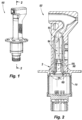
Fig. 1 is a perspective view of a system in accordance with this disclosure, showing an embodiment of a housing assembly; -
Fig. 2 is a cross sectional view of the system ofFig. 1 , showing an element assembly within the housing assembly, the element assembly including a component; -
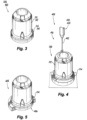
Fig. 3 is a perspective view of the component ofFig 2 ; -
Fig. 4 is a schematic view of a method of making an embodiment of the component ofFig. 3 , showing an additive manufacturing process; -
Fig. 5 is a schematic view of a method of making an embodiment of the component ofFig. 3 , showing a machining process; -
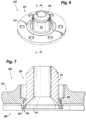
Fig. 6 is an elevational view of the embodiment of the component made by the processes ofFigs. 4 and 5 ; -
Fig. 7 is a schematic view of a method of installation of the component into the housing assembly; -
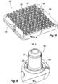
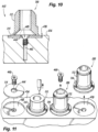
Figs. 8-11 show a schematic view of a method of making a plurality of the components ofFig. 3 ; -
Fig. 12 is a schematic view of a method of making an embodiment of the component ofFig. 3 ; -
Fig. 13 is a schematic view of a method of making an embodiment of the component ofFig. 3 , showing a machining process; -
Fig. 14 is an elevational view of the embodiment of the component made by the processes ofFigs. 12 and 13 ; and -
Fig. 15 is a schematic view of a method of installation of the component into the housing assembly. - Reference will now be made to the drawings wherein like reference numerals identify similar structural features or aspects of the subject disclosure. For purposes of explanation and illustration, and not limitation, an illustrative view of an embodiment of a system in accordance with the disclosure is shown in
Fig. 1 and is designated generally byreference character 100. Other embodiments and/or aspects of this disclosure are shown inFigs. 2-15 . - In accordance with at least one aspect of this disclosure, as shown in
Figs. 1 and 2 , a system 100 (e.g., a system for air data sensing) can include, ahousing assembly 102 and anelement assembly 104. Theelement assembly 104 can include a dual-material component element assembly 104 to thehousing assembly 102, theelement assembly 104 can be joined to and within thehousing assembly 102 via aweld joint 106 at aweld interface 108 between the dual-material component housing assembly 102. Thesystem 100 can also include abase assembly 110, where thebase assembly 110 is installed to thehousing assembly 102 after theelement assembly 104 is welded to thehousing assembly 102 via the dual-material component - In embodiments, such as shown in
Fig. 3 , the dual-material component can include an additively manufacturedcomponent portion base portion component portion housing assembly 102, and thebase portion housing assembly 102. In certain applications, the first material may not be compatible for welding with the material of thehousing assembly 102. - For example, in certain applications, the
component portion housing assembly 102. Therefore, the dual-material component base portion housing assembly 102 to ensure both thecomponent portion component housing assembly 102. In certain embodiments, the metallic properties of the first and second materials can include, among other things: the first material can have a higher thermal conductivity than the second material. Material properties may also be selected to promote welding and brazing between components or transitioning between varying coefficients of thermal expansion. - In certain embodiments, the dual-
material component 200 can be a nickel-stainless steel component, where the additively manufacturedcomponent portion 212 is of nickel (e.g., nickel 200) and thebase portion 214 is of stainless steel such that thebase portion 214 provides a similar metal for welding to thehousing assembly 102, which is of stainless steel, in embodiments. Amethod 400 of manufacturing thecomponent 200 is described herein with respect toFigs. 4-11 . - In certain embodiments, the dual-
material component 300 can be a nickel-Inconel component, where the additively manufacturedcomponent portion 312 is of nickel (e.g., nickel 200) and thebase portion 314 is of Inconel (e.g., Inconel 625), such that thebase portion 214 provides a compatible metal for welding to thehousing assembly 102, which is of stainless steel, in embodiments. The two dissimilar metals of stainless steel and Inconel 625 can be suitable for forming a compatible allow system at the weld interface. Amethod 500 of manufacturing thecomponent 300 is described herein with respect toFigs. 12-15 . - With reference now to
Figs. 4-11 , amethod 400 of making a dual-material component (e.g., component 200) includes, additively manufacturing 416 thecomponent portion 212 from the first material onto a baseplate (e.g., the base portion 214) manufactured from the second material.Additive manufacturing 416 can include additively manufacturing using anenergy source 418 to fuse metallic powder on a powder bed (e.g., laser powder bed fusion as shown inFig. 4 .), or powder or wire ejected from anozzle 420 with anenergy beam 422 from the energy source (e.g., directed energy deposition shown inFig. 12 .). Any suitable additive manufacturing technique is contemplated herein as would be appreciated by those having ordinary skill in the art in view of this disclosure. - In embodiments, as shown in
Fig. 5 , themethod 400 can further include machining 424 thebase plate 214 to apredetermined geometry 426 corresponding to acomponent seat 428 within the housing assembly 102 (the component seat shown inFig. 7 within a sensor base plate 431). After machining 424, thecomponent 200 can take the form shown inFig. 6 , where the diameter of thebaseplate 214 matches a diameter of thecomponent portion 212. Themethod 400 can further include, as shown inFig. 7 , installing 429 the dual-material component 200 into thecomponent seat 428 of thehousing assembly 102, and welding 430 thebase plate 214 of the dual-material component 200 to thehousing assembly 102 at theweld interface 106 to form the weld joint 108 to secure the dual-material component 200 to thehousing assembly 102. In embodiments, themethod 400 can include separately manufacturing thebase plate 214 from the second material, e.g., prior to additively manufacturing 416 thecomponent portion 212 to thebase plate 214. - In certain embodiments, as shown in
Figs. 8-11 , themethod 400 can include producing a plurality ofcomponents 200 at the same time. As shown, themethod 400 can also include manufacturing 432 abuild plate 434 configured to hold one ormore base plates 214 and installing the one ormore base plates 214 into thebuild plate 434. In certain such embodiments, manufacturing 432 the build plate can further include forming 436 a plurality of base plate recesses 438 in thebuild plate 434 and forming 440 a respective build plate bore 442 in eachbase plate recess 438 of the plurality of base plate recesses 438. In such embodiments, manufacturing thebase plate 214 can further include forming a respective base plate bore 444 in eachbase plate 214. - In embodiments, the one or
more base plates 214 can include a plurality ofbase plates 214, and themethod 400 can further include installing 446 the plurality ofbase plates 214 into thebuild plate 434 can include, placing arespective base plate 214 into a respectivebase plate recess 438, and securing eachrespective base plate 214 to thebuild plate 434 in the respectivebase plate recess 438 with arespective fastener 448 extending through the respective base plate bore 444 and into the respectivebuild plate bore 442. As such, themethod 400 can include additively manufacturing a plurality ofcomponents 200 of the first material onto each of therespective base plates 214 to manufacture a plurality of dual-material components 200 on thesame build plate 434. - Referring now to
Figs. 12-15 , amethod 500 of manufacturing a dual-material component (e.g., component 300) can include, additively manufacturing 516 thecomponent portion 312 from a first material. Additive manufacturing 516 can be similar toadditive manufacture 416, but additive manufacturing 516 can be remote to the rest of themethod 500 and thecomponent portion 312 can be manufactured on a conventional build plate, for example. Themethod 500 further includes cladding/directedenergy deposition 550 thebase portion 314 onto thecomponent portion 312 to form the dual-material component 300 for use in thehousing assembly 102. In embodiments, cladding 550 thebase portion 314 onto thecomponent portion 312 can include applying with acladding nozzle 552, the second material to thecomponent portion 312 to grow thebase portion 314 from thecomponent portion 312 to manufacture the dual-material component 300. - The
method 500 can further include, as shown inFig. 13 , machining 524 thebase portion 314 to apredetermined geometry 526 corresponding to acomponent seat 528 within the housing assembly 102 (the component seat shown inFig. 15 within a sensor base plate 531). After machining 524, thecomponent 300 can take the form shown inFig. 14 , where the diameter of thebaseplate 314 matches a diameter of thecomponent portion 312. In embodiments, as shown inFig. 15 , themethod 500 can include, installing 529 thecomponent 300 into the component seat 538 of thehousing assembly 102, and welding 530 thebase plate 314 of thecomponent 300 to thehousing assembly 102 at theweld interface 106 to form the weld joint 108 to secure thecomponent 300 to theassembly 102. -
Nickel 200 has proven to provide superior thermal management properties for given applications, for example in air data sensing systems. However thatsame nickel 200 component (e.g.,component 200, 300) needs to be laser welded to another stainless steel component (e.g., in the housing assembly 102).Nickel 200 and stainless steel are dissimilar metals that create a tricky weld which can be susceptible to hot cracking. Thedual material component component portion 212, 312) and one for weldability (e.g., thebase portion 214, 314), overcoming the noted challenges. - As described herein,
methods dual material component base portion 214, 314) could be stainless steel or Inconel. Both are described herein. - In certain embodiments, the
dual material component 200 can be created using a stainless steel base material was attached to an additive manufacturing build plate. Then anickel 200 component can be grown on top of the stainless steel base material. Next, the excess base material can be machined away creating thedual material component 200. This process is shown inFigs. 4-7 . Thiscomponent 200 can have all the thermal properties required to perform well in heat and has a weld flange (e.g., base portion 214) of similar metals so it can be assembled easily and of high quality. The best quality weld would be stainless-steel to stainless-steel, thus in this embodiment, the base portion weld flange can be stainless steel. Using certain additive manufacturing techniques, such as laser powder bed fusion, thenickel portion 212 of thecomponent 200 is built in an inert environment and using a very precise set of laser welds. This produces a high quality weld with improved weld adhesion to the stainless steel build plate. However, traditionally, when laser welding an all nickel component to theassembly 102, it may not be possible to get the same weld quality without the inert environment and precise laser placement, especially the component is being laser welded by hand. Thus, as described herein,nickel 200 component portion is able to be built onto the stainless steel base plate and allows provides for the similar metals (stainless to stainless) during the more difficult weld of welding thecomponent 200 to the assembly. - In certain embodiments of the
additive manufacturing method 400, to streamline the manufacturing process, special build plates (e.g., build plate 434) can be used with stainless steel blanks (e.g., base plates 214) to act as the base material. Each potting well (component 200) can be printed onto a blank which will limit the amount of wasted blank material and make post process machining easier and more consistent. This streamlined process is shown inFigs. 8-11 . - In certain embodiments, the
dual material component 300 can be created using am Inconel base material to for the weld flange so that the laser weld would be Inconel to stainless-steel when thecomponent 300 is installed into theassembly 102. - The
method 500 for creating thecomponent 300 using Inconel cladding can include first creating the main body of the component without the weld interface using any suitable method (e.g., additive manufacturing, casting). Next, Inconel material can be clad onto the main body and any excess cladded Inconel can be machined away. This can thus create the dual material potting well 300 that is ofnickel 200 with an Inconel weld interface. This process is shown inFig. 12-15 . - Using any embodiment of the
methods dual material components - In practice, most of the heat generated in the system 100 (e.g.,
Figures 1 and 2 ) is at the scoop of the sensor. That heat then flows down thehousing assembly 102, to thesensor baseplate element assembly 104. If the temperature sits for too long inelement assembly 104 and specifically the potting well (e.g.,component 200, 300), the electronics material within the inner diameter of the potting well can overheat and become damaged. Thus, embodiments allow for the element assembly to move the heat as fast as possible through that area of the assembly. Embodiments includenickel 200 for thecomponent portion 213, 312, as it has good thermal conductivity, anti-corrosion properties, it can be welded to Inconel 625 (which, in embodiments, is what the flow duct (the structure surrounding the potting well) is made from.Nickel 200 can also be additively manufactured, which is advantageous for manufacturing the complex design of thecomponent portion sensor baseplate 431, 531). A very high quality weld is required for that joint as it acts as a hermetic seal. - The articles "a", "an", and "the" as used herein and in the appended claims are used herein to refer to one or to more than one (i.e., to at least one) of the grammatical object of the article unless the context clearly indicates otherwise. By way of example, "an element" means one element or more than one element.
- The phrase "and/or," as used herein in the specification and in the claims, should be understood to mean "either or both" of the elements so conjoined, i.e., elements that are conjunctively present in some cases and disjunctively present in other cases. Multiple elements listed with "and/or" should be construed in the same fashion, i.e., "one or more" of the elements so conjoined. Other elements may optionally be present other than the elements specifically identified by the "and/or" clause, whether related or unrelated to those elements specifically identified. Thus, as a non-limiting example, a reference to "A and/or B", when used in conjunction with open-ended language such as "comprising" can refer, in one embodiment, to A only (optionally including elements other than B); in another embodiment, to B only (optionally including elements other than A); in yet another embodiment, to both A and B (optionally including other elements); etc.
- As used herein in the specification and in the claims, "or" should be understood to have the same meaning as "and/or" as defined above. For example, when separating items in a list, "or" or "and/or" shall be interpreted as being inclusive, i.e., the inclusion of at least one, but also including more than one, of a number or list of elements, and, optionally, additional unlisted items. Only terms clearly indicated to the contrary, such as "only one of" or "exactly one of," or, when used in the claims, "consisting of," will refer to the inclusion of exactly one element of a number or list of elements. In general, the term "or" as used herein shall only be interpreted as indicating exclusive alternatives (i.e., "one or the other but not both") when preceded by terms of exclusivity, such as "either," "one of," "only one of," or "exactly one of."
- Any suitable combination(s) of any disclosed embodiments and/or any suitable portion(s) thereof are contemplated herein as appreciated by those having ordinary skill in the art in view of this disclosure.
- The embodiments of the present disclosure, as described above and shown in the drawings, provide for improvement in the art to which they pertain. While the apparatus and methods of the subject disclosure have been shown and described, those skilled in the art will readily appreciate that changes and/or modifications may be made thereto without departing from the scope of the subject disclosure.
Claims (15)
- A method, comprising:
additively manufacturing a component (200, 300) from a first material onto a baseplate (214, 314) manufactured of a second material to form a dual-material component (200, 300) for use in an assembly, wherein the first material is configured to manage heat within the assembly and wherein the second material is configured to form a weld joint between the base plate of the dual-material component (200, 300) and the assembly for joining the dual-material component (200, 300) to the assembly. - The method of claim 1, further comprising, machining the base plate to a predetermined geometry corresponding to a component seat within the assembly.
- The method of any preceding claim, further comprising:installing the dual-material component (200, 300) into the component seat of the assembly; andwelding the base plate of the dual-material component (200, 300) to the assembly at the weld interface to form a weld joint to secure the dual-material component (200, 300) to the assembly.
- The method of any preceding claim, further comprising, manufacturing the base plate from the second material.
- The method of claim 4, further comprising, manufacturing a build plate configured to hold one or more base plates and installing the one or more base plates into the build plate.
- The method of claim 5, wherein manufacturing the build plate further comprises:forming a plurality of base plate recesses in the build plate; andforming a respective build plate bore in each base plate recess of the plurality of base plate recesses, and wherein manufacturing the base plate further comprises;forming a respective base plate bore in each base plate.
- The method of claim 6, wherein the one or more base plates includes a plurality of base plates, wherein installing the plurality of base plates into the build plate further comprises,placing a respective base plate into a respective base plate recess; andsecuring each respective base plate to the build plate in the respective base plate recess with a respective fastener extending through the respective base plate bore and into the respective build plate bore, and optionally . further comprising, additively manufacturing a plurality of components of the first material onto each of the respective base plates to manufacture a plurality of dual-material components on the same build plate.
- The method of any preceding claim, wherein the first material is different from the second material, and wherein the second material is the same as a material of the assembly at the weld interface, wherein the first material has a higher thermal conductivity than the second material, and optionally wherein the first material is nickel, wherein the second material is stainless steel, and wherein the material of the assembly at the weld interface is stainless steel.
- A method, comprising:additively manufacturing a component (200, 300) from a first material; andcladding a base portion of a second material onto the component (200, 300) to form a dual-material component (200, 300) for use in an assembly, wherein the first material is configured to manage heat within the assembly and wherein the second material is configured to form a weld joint between the base portion of the component (200, 300) and the assembly for joining the component (200, 300) to the assembly.
- The method of claim 9, wherein cladding the base portion onto the component (200, 300) further comprises, applying with a cladding nozzle, the second material to the first material to grow the base portion from the component (200, 300) to manufacture the dual-material component (200, 300).
- The method of claim 10, further comprising, machining the base portion to a predetermined geometry corresponding to a component seat within the assembly, and optionally further comprising:installing the component (200, 300) into the component seat of the assembly; andwelding the base plate of the component (200, 300) to the assembly at the weld interface to form a weld joint to secure the component (200, 300) to the assembly.
- The method of claim 9, wherein the first material is different from the second material, and wherein the second material is different than a material of the assembly at the weld interface and configured to form a compatible alloy with the assembly, wherein the first material has a higher thermal conductivity than the second material, and optionally . wherein the first material is nickel, wherein the second material is Inconel, and wherein the material of the assembly at the weld interface is stainless steel.
- A system, comprising:a housing assembly; andan element assembly having a dual-material component (200, 300) therein, the element assembly joined within the housing assembly via a weld joint at a weld interface between the dual-material component (200, 300) and the housing assembly.
- The system of claim 13, wherein the dual-material component (200, 300) comprises an additively manufactured component portion and a base portion, wherein the additively manufactured component portion is additively manufactured of a first material configured to manage heat within the housing assembly, and wherein the base portion is manufactured of a second material, different than the first material and compatible for welding and forming an alloy with a material of the housing assembly, wherein the first material has a higher thermal conductivity than the second material.
- The system of claim 14, wherein the additively manufactured component portion is of nickel, wherein the base portion is of stainless steel, and wherein the housing assembly is of stainless steel, or wherein the additively manufactured component portion is of nickel, wherein the base portion is of Inconel, and wherein the housing assembly is of stainless steel.
Applications Claiming Priority (1)
| Application Number | Priority Date | Filing Date | Title |
|---|---|---|---|
| US18/231,148 US20250050418A1 (en) | 2023-08-07 | 2023-08-07 | Dual-material components and methods of making therefor |
Publications (2)
| Publication Number | Publication Date |
|---|---|
| EP4506086A2 true EP4506086A2 (en) | 2025-02-12 |
| EP4506086A3 EP4506086A3 (en) | 2025-04-23 |
Family
ID=92264098
Family Applications (1)
| Application Number | Title | Priority Date | Filing Date |
|---|---|---|---|
| EP24193391.0A Pending EP4506086A3 (en) | 2023-08-07 | 2024-08-07 | Dual-material components and methods of making therefor |
Country Status (2)
| Country | Link |
|---|---|
| US (1) | US20250050418A1 (en) |
| EP (1) | EP4506086A3 (en) |
Cited By (1)
| Publication number | Priority date | Publication date | Assignee | Title |
|---|---|---|---|---|
| EP4703068A1 (en) * | 2024-08-30 | 2026-03-04 | Relativity Space, Inc. | Additive manufacturing of hybrid structures |
Families Citing this family (2)
| Publication number | Priority date | Publication date | Assignee | Title |
|---|---|---|---|---|
| USD1110868S1 (en) * | 2024-02-09 | 2026-02-03 | Rosemount Aerospace Inc. | Aircraft total air temperature sensor |
| USD1110867S1 (en) * | 2024-02-09 | 2026-02-03 | Rosemount Aerospace Inc. | Aircraft total air temperature sensor |
Family Cites Families (4)
| Publication number | Priority date | Publication date | Assignee | Title |
|---|---|---|---|---|
| FR2951971B1 (en) * | 2009-11-03 | 2011-12-09 | Michelin Soc Tech | SUPPORT PLATE FOR LASER SINTERING DEVICE AND IMPROVED SINKING METHOD |
| US10493532B2 (en) * | 2017-01-17 | 2019-12-03 | General Electric Company | Thermal expansion fit build plate for additive manufacturing |
| US11826831B2 (en) * | 2020-01-10 | 2023-11-28 | Ford Global Technologies, Llc | Methods for additive manufacturing a part and parts formed according to the methods |
| WO2021258192A1 (en) * | 2020-06-26 | 2021-12-30 | Safran Landing Systems Canada Inc. | Additive manufactured landing gear brace using preformed extruded metal as base material |
-
2023
- 2023-08-07 US US18/231,148 patent/US20250050418A1/en active Pending
-
2024
- 2024-08-07 EP EP24193391.0A patent/EP4506086A3/en active Pending
Cited By (1)
| Publication number | Priority date | Publication date | Assignee | Title |
|---|---|---|---|---|
| EP4703068A1 (en) * | 2024-08-30 | 2026-03-04 | Relativity Space, Inc. | Additive manufacturing of hybrid structures |
Also Published As
| Publication number | Publication date |
|---|---|
| US20250050418A1 (en) | 2025-02-13 |
| EP4506086A3 (en) | 2025-04-23 |
Similar Documents
| Publication | Publication Date | Title |
|---|---|---|
| US20250050418A1 (en) | Dual-material components and methods of making therefor | |
| JP5943958B2 (en) | Configuration for bonding ceramic insulation materials to metal structures | |
| Dawes | Laser welding: a practical guide | |
| US6129257A (en) | High temperature brazing fixture | |
| EP2098324A1 (en) | Welded butt joints on tubes having dissimilar end preparations | |
| EP3345708A1 (en) | Method, brazed article, and brazing assembly | |
| CN209811451U (en) | heat exchanger element | |
| CN109759789A (en) | The thrust chamber pressure resistance interlayer manufacturing method of liquid-propellant rocket engine | |
| EP2495065A2 (en) | Stainless steel joining method | |
| US20190201995A1 (en) | Deposition of braze preform | |
| JP3457289B2 (en) | Thick plate welding method by combination of laser welding and TIG welding or MIG welding | |
| US10478920B2 (en) | Dual wall components for gas turbine engines | |
| US11420280B2 (en) | Closed socket brazed joint assembly | |
| JP5372436B2 (en) | Use of active flux for TIG welding of metal parts | |
| US20080008898A1 (en) | System, method, and apparatus for three-dimensional woven metal preform structural joint | |
| US7767318B2 (en) | Laser fillet welding | |
| CN111163884A (en) | System and method for bridging components | |
| JP4897668B2 (en) | Manufacturing method of honeycomb seal | |
| CN116213866B (en) | Dissimilar metal joint welding method and dissimilar metal welded joint | |
| EP3144505B1 (en) | Gas turbine component and method of forming | |
| EP1925391A1 (en) | Laser fillet welding | |
| US12251769B2 (en) | Closed socket brazed joint assembly | |
| Naeem | High Power Fiber Laser Welding with Filler Material: Very good results for welding aluminium, titanium, and high strength nickel alloys achieved with wire or powder feed setups | |
| JP2017035721A (en) | Laser welded joint | |
| CN121576190A (en) | A composite manufacturing method for rapid prototyping of hollow cylindrical structures |
Legal Events
| Date | Code | Title | Description |
|---|---|---|---|
| PUAI | Public reference made under article 153(3) epc to a published international application that has entered the european phase |
Free format text: ORIGINAL CODE: 0009012 |
|
| STAA | Information on the status of an ep patent application or granted ep patent |
Free format text: STATUS: THE APPLICATION HAS BEEN PUBLISHED |
|
| AK | Designated contracting states |
Kind code of ref document: A2 Designated state(s): AL AT BE BG CH CY CZ DE DK EE ES FI FR GB GR HR HU IE IS IT LI LT LU LV MC ME MK MT NL NO PL PT RO RS SE SI SK SM TR |
|
| PUAL | Search report despatched |
Free format text: ORIGINAL CODE: 0009013 |
|
| AK | Designated contracting states |
Kind code of ref document: A3 Designated state(s): AL AT BE BG CH CY CZ DE DK EE ES FI FR GB GR HR HU IE IS IT LI LT LU LV MC ME MK MT NL NO PL PT RO RS SE SI SK SM TR |
|
| RIC1 | Information provided on ipc code assigned before grant |
Ipc: B22F 12/30 20210101ALI20250318BHEP Ipc: B22F 7/06 20060101ALI20250318BHEP Ipc: B23K 15/00 20060101ALI20250318BHEP Ipc: B33Y 80/00 20150101ALI20250318BHEP Ipc: B33Y 10/00 20150101ALI20250318BHEP Ipc: B23K 26/342 20140101ALI20250318BHEP Ipc: B22F 10/28 20210101ALI20250318BHEP Ipc: B22F 10/25 20210101ALI20250318BHEP Ipc: B22F 7/08 20060101AFI20250318BHEP |
|
| STAA | Information on the status of an ep patent application or granted ep patent |
Free format text: STATUS: REQUEST FOR EXAMINATION WAS MADE |
|
| 17P | Request for examination filed |
Effective date: 20251023 |