EP4506081A1 - Bottomed metal cylinder - Google Patents
Bottomed metal cylinder Download PDFInfo
- Publication number
- EP4506081A1 EP4506081A1 EP23784515.1A EP23784515A EP4506081A1 EP 4506081 A1 EP4506081 A1 EP 4506081A1 EP 23784515 A EP23784515 A EP 23784515A EP 4506081 A1 EP4506081 A1 EP 4506081A1
- Authority
- EP
- European Patent Office
- Prior art keywords
- dome
- doming
- die
- peripheral edge
- shaped bottom
- Prior art date
- Legal status (The legal status is an assumption and is not a legal conclusion. Google has not performed a legal analysis and makes no representation as to the accuracy of the status listed.)
- Pending
Links
Images




Classifications
-
- B—PERFORMING OPERATIONS; TRANSPORTING
- B65—CONVEYING; PACKING; STORING; HANDLING THIN OR FILAMENTARY MATERIAL
- B65D—CONTAINERS FOR STORAGE OR TRANSPORT OF ARTICLES OR MATERIALS, e.g. BAGS, BARRELS, BOTTLES, BOXES, CANS, CARTONS, CRATES, DRUMS, JARS, TANKS, HOPPERS, FORWARDING CONTAINERS; ACCESSORIES, CLOSURES, OR FITTINGS THEREFOR; PACKAGING ELEMENTS; PACKAGES
- B65D1/00—Rigid or semi-rigid containers having bodies formed in one piece, e.g. by casting metallic material, by moulding plastics, by blowing vitreous material, by throwing ceramic material, by moulding pulped fibrous material or by deep-drawing operations performed on sheet material
- B65D1/12—Cans, casks, barrels, or drums
- B65D1/14—Cans, casks, barrels, or drums characterised by shape
- B65D1/16—Cans, casks, barrels, or drums characterised by shape of curved cross-section, e.g. cylindrical
- B65D1/165—Cylindrical cans
-
- B—PERFORMING OPERATIONS; TRANSPORTING
- B21—MECHANICAL METAL-WORKING WITHOUT ESSENTIALLY REMOVING MATERIAL; PUNCHING METAL
- B21D—WORKING OR PROCESSING OF SHEET METAL OR METAL TUBES, RODS OR PROFILES WITHOUT ESSENTIALLY REMOVING MATERIAL; PUNCHING METAL
- B21D22/00—Shaping without cutting, by stamping, spinning, or deep-drawing
- B21D22/20—Deep-drawing
- B21D22/28—Deep-drawing of cylindrical articles using consecutive dies
-
- B—PERFORMING OPERATIONS; TRANSPORTING
- B21—MECHANICAL METAL-WORKING WITHOUT ESSENTIALLY REMOVING MATERIAL; PUNCHING METAL
- B21D—WORKING OR PROCESSING OF SHEET METAL OR METAL TUBES, RODS OR PROFILES WITHOUT ESSENTIALLY REMOVING MATERIAL; PUNCHING METAL
- B21D22/00—Shaping without cutting, by stamping, spinning, or deep-drawing
- B21D22/20—Deep-drawing
- B21D22/30—Deep-drawing to finish articles formed by deep-drawing
-
- B—PERFORMING OPERATIONS; TRANSPORTING
- B21—MECHANICAL METAL-WORKING WITHOUT ESSENTIALLY REMOVING MATERIAL; PUNCHING METAL
- B21D—WORKING OR PROCESSING OF SHEET METAL OR METAL TUBES, RODS OR PROFILES WITHOUT ESSENTIALLY REMOVING MATERIAL; PUNCHING METAL
- B21D24/00—Special deep-drawing arrangements in, or in connection with, presses
-
- B—PERFORMING OPERATIONS; TRANSPORTING
- B21—MECHANICAL METAL-WORKING WITHOUT ESSENTIALLY REMOVING MATERIAL; PUNCHING METAL
- B21D—WORKING OR PROCESSING OF SHEET METAL OR METAL TUBES, RODS OR PROFILES WITHOUT ESSENTIALLY REMOVING MATERIAL; PUNCHING METAL
- B21D37/00—Tools as parts of machines covered by this subclass
- B21D37/10—Die sets; Pillar guides
-
- B—PERFORMING OPERATIONS; TRANSPORTING
- B21—MECHANICAL METAL-WORKING WITHOUT ESSENTIALLY REMOVING MATERIAL; PUNCHING METAL
- B21D—WORKING OR PROCESSING OF SHEET METAL OR METAL TUBES, RODS OR PROFILES WITHOUT ESSENTIALLY REMOVING MATERIAL; PUNCHING METAL
- B21D51/00—Making hollow objects
- B21D51/16—Making hollow objects characterised by the use of the objects
- B21D51/26—Making hollow objects characterised by the use of the objects cans or tins; Closing same in a permanent manner
-
- B—PERFORMING OPERATIONS; TRANSPORTING
- B21—MECHANICAL METAL-WORKING WITHOUT ESSENTIALLY REMOVING MATERIAL; PUNCHING METAL
- B21D—WORKING OR PROCESSING OF SHEET METAL OR METAL TUBES, RODS OR PROFILES WITHOUT ESSENTIALLY REMOVING MATERIAL; PUNCHING METAL
- B21D51/00—Making hollow objects
- B21D51/16—Making hollow objects characterised by the use of the objects
- B21D51/26—Making hollow objects characterised by the use of the objects cans or tins; Closing same in a permanent manner
- B21D51/2669—Transforming the shape of formed can bodies; Forming can bodies from flattened tubular blanks; Flattening can bodies
Definitions
- the present invention relates to a bottomed metal cylinder having a dome-shaped bottom surface, such as a seamless metal can, for example, and further relates to a molding die used for molding the dome-shaped bottom surface and to a doming method using the molding die.
- a bottom portion is recessed into a dome shape to reduce weight, improve pressure resistance performance, and stabilize placement.
- the molding of such a bottom portion is called doming, and is performed by holding a bottom portion peripheral edge of the cylinder by an annular die called a hold ring and pushing up a doming die from within the annular mold, thereby recessing a bottom surface of the cylinder into a dome shape (refer to Patent Document 1).
- the dome-shaped bottom surface formed as described above has a problem in that wrinkling is likely to occur at a peripheral edge portion. Such wrinkling is particularly noticeable on aluminum cans. These wrinkles, being formed at a bottom surface, have not been significantly problematic in the past.
- beverage cans, such as aluminum seamless cans, nowadays are often placed and sold with the bottom portion of the can being visible, resulting in a recent demand for improvement.
- Patent Document 1 JP 2018-177289 A
- an object of the present invention is to provide a bottomed metal cylinder including a dome-shaped bottom portion that is wrinkle-free.
- Another object of the present invention is to provide a molding die used for dome molding (doming) a bottom portion of the bottomed metal cylinder described above and a dome molding method using the molding die.
- a bottomed metal cylinder including, at a bottom portion, a ground contact portion, a rising portion extending upward from an inner side of the ground contact portion, and a dome-shaped bottom surface extending to the rising portion.
- An annular line is observed at a peripheral edge portion of the dome-shaped bottom surface.
- a molding die used for dome-molding a bottom portion of a bottomed metal cylinder.
- the molding die includes an annular holding die for holding a bottom portion peripheral edge of the bottomed metal cylinder, and a doming die for defining a dome-shaped bottom surface.
- the doming die is divided into a doming ring for defining a peripheral edge portion of the dome-shaped bottom surface and a base die for defining a center portion of the dome-shaped bottom surface inward of the peripheral edge portion.
- the doming ring and the base die are each independently vertically movable.
- a method for doming a bottom portion of a bottomed metal cylinder includes preparing the molding die described above, lowering a punch sleeve from inside the bottomed metal cylinder and pressing a lower end peripheral edge portion of the cylinder against a working surface of the annular holding die, to form a chime portion and a ground contact portion at a bottom surface peripheral edge portion of the cylinder, raising the doming ring while holding the chime portion and the ground contact portion of the cylinder by the punch sleeve and the working surface of the annular holding die to form a rising portion and a peripheral edge portion of a dome-shaped bottom surface inside the ground contact portion, and arranging a base die to form a center portion of the dome-shaped bottom surface.
- a bottomed metal cylinder according to the present invention includes a dome-shaped bottom surface recessed into a dome shape, a dome-shaped peripheral edge portion thereof being free of wrinkles and, instead, observed as including an annular line.
- a die used for molding that is, dome-molding
- a cylinder bottom portion is divided into a doming ring for defining a peripheral edge portion of a dome-shaped bottom surface and a base die for defining a center portion of the dome-shaped bottom surface inward of the peripheral edge portion, and a surface of the peripheral edge portion of the dome-shaped bottom surface is formed by a dedicated die called a doming ring.
- the annular line is observed in the peripheral edge portion of the dome-shaped bottom surface instead of wrinkles, thereby making it possible to not impair appearance and secure a high commercial value when the metal cylinder is used as a beverage can, for example.
- a bottomed metal cylinder according to the present invention is obtained by, for example, punching, drawing, and redrawing-ironing a thin element plate made of metal, then doming a bottom portion thereof and, lastly, subsequently performing post-processing such as washing and drying, outer surface printing, finishing varnish application and baking, inner surface coating application and baking, neck-in processing, and flange processing.
- the final form is typically, as a whole, as illustrated in FIG. 1 .
- the bottomed metal cylinder according to the present invention denoted by 10 as a whole includes a body portion 1 provided with an outer surface having a straight cylindrical shape, a ground contact portion 5 formed from a lower end of the body portion 1 with a chime portion 3, inclined inwardly, interposed therebetween, and a dome-shaped bottom surface 7 positioned in a region surrounded by the ground contact portion 5. Further, an upper portion of the body portion 1 extends to a neck-in portion 8 formed by post-processing, and a flange portion 9 is formed on an upper end of the neck-in portion 8.
- the dome-shaped bottom surface 7 is composed of a peripheral edge portion 7a extending to an upper end of a rising portion 6 rising inwardly from the ground contact portion 5, and a center portion 7b surrounded by the peripheral edge portion 7a.
- the peripheral edge portion 7a corresponds to a portion with which a doming ring used at the time of doming described below comes into contact, and has a length of about 2 to 30 mm in a side cross-sectional view.
- Such a dome-shaped bottom surface 7 composed of the peripheral edge portion 7a and the center portion 7b has a large, substantially constant radius of curvature as a whole in a side cross-sectional view and, with formation of the bottom surface 7 in such a form at the bottom portion, it is possible to stably place this bottomed cylinder 10 and further increase a load strength thereof in an axial direction.
- the metal constituting the bottomed cylinder 10 described above is not particularly limited and may be various metals or alloys, but aluminum or an aluminum alloy is preferable from viewpoints such as weight reduction and thin-wall workability, and a seamless can coated on an inner surface with an organic resin is preferable from the viewpoint of taking advantage of the merits of the present invention.
- an important feature of the present invention is that an annular line 11 is observed at a boundary portion between the peripheral edge portion 7a and the center portion 7b of the dome-shaped bottom surface 7 described above.
- a thickness t 0 at this annular line 11 originating from a local thin portion is a thickness reduced by about 3 to 5% relative to a thickness t 1 at a position approximately 0.5 mm inward of the peripheral edge portion 7a, and the wrinkles X are eliminated by stretching. That is, in the present invention, the annular line 11 is formed instead of the wrinkles X.
- a thickness of the dome-shaped top surface 7 at a center portion O typically corresponds to a thickness of the thin element material plate used for this molding, and a thickness of the body portion 1 is determined in accordance with a degree of ironing (ironing rate).
- a thickness of the element plate is about 0.180 to 0.350 mm, and a thickness of the thinnest area of the body portion 1 is 30 to 50% of that of the element plate.
- the bottomed metal cylinder 10 according to the present invention having a form such as described above is manufactured by molding using the metal element plate described above (organic resin coating may be provided on the side corresponding to the inner surface).
- the bottomed cylinder 10 including the dome-shaped bottom surface 7 is obtained by punching, drawing, ironing, and doming as usual.
- This process from punching to doming is illustrated in FIG. 5 .
- an element plate 21 is punched by a punching punch 23 and a punching die 25 to obtain a circular plate 27 (punching process).
- a drawn cup (bottomed cylinder) 35 is obtained by a drawing die 31 and a drawing punch 33 (drawing process).
- the obtained drawn cup 35 may be subjected to a doming process described below, but typically a re-drawing process and an ironing process are continuously performed as needed.
- the drawn cup 35 held in a redraw die 43 by a presser 41 is pushed downward using an ironing punch 45, ironing is then performed through a plurality of ironing dies 47a to 47c, and subsequently doming is performed at the lowermost position.
- This doming is performed using a hold-down ring 51 and a doming die 61 described below.
- the dome-shaped bottom surface 7 is formed simultaneously with the chime portion 3 and the ground contact portion 5 described above.
- a stripper finger 53 is used to pull out the molded seamless can (bottomed metal cylinder) 10 from the punch 45, thereby completing this process. Subsequent post-processing, such as washing and drying and neck-in processing, is then performed.
- the number of the ironing dies is not limited to three, and may be set to an appropriate number in accordance with a degree of intended thinning, and one die may be used for ironing in one stage, or two or more dies may be arranged for ironing in a plurality of stages. It is obvious that, in the case of a plurality of ironing dies being arranged in a processing direction and ironing being performed in a plurality stages, an inner diameter (working diameter) becomes smaller downstream in the processing direction.
- the molding die used for doming includes the hold-down ring (annular holding die) 51 and a doming die 60, and doming is performed by a cooperative action of these molding dies and the punch 45.
- the doming die 60 is divided into the base die 61 and a doming ring 63, and these are each provided independently vertically movable, which is an important feature.
- a working surface 51a at an upper end is inclined inwardly downward, the chime portion 3 extending to the lower end of the body portion 1 is formed by this working surface 51a, and the ground contact surface 5 is formed at a lower end of the working surface 51a.
- the base die 61 is a die that defines the center portion 7b of the dome-shaped bottom surface 7, and a working surface 61a at an upper end thereof is a surface that corresponds to the center portion 7b of the dome-shaped bottom surface 7.
- the doming ring 63 is a die that defines the peripheral edge portion 7a of the dome-shaped bottom surface 7, and a working surface 63a at an upper end thereof is a surface that corresponds to the peripheral edge portion 7a of the dome-shaped bottom surface 7.
- the peripheral edge portion 7a of the dome-shaped bottom surface 7 is a portion where wrinkles are likely to occur and, with the die surface defining this portion made separate from the die surface defining the center portion 7b, stresses applied to the peripheral edge portion 7a of the dome-shaped bottom surface 7 are concentrated, thereby stretching the wrinkles that would thereby occur, avoiding the occurrence of wrinkles, and causing the annular line 11 to appear at a position corresponding to an inner end portion of the working surface 63a of the doming ring 63. That is, a length of this working surface 63a corresponds to a length of the peripheral edge portion 7a of the dome-shaped bottom surface 7 in a side cross-sectional view.
- Doming using the molding die described above is carried out by the process illustrated in FIG. 7 .
- the hold-down ring 51 is urged upward by air (not illustrated) and, in the initial stage, as illustrated in FIG. 7(a) , the working surface 63a of the doming ring 63 is positioned downward of the working surface 51a of the hold-down ring 51, and the working surface 61a of the base die 61 is positioned further downward of the working surface 63a of the doming ring 63.
- the ground contact portion 5 is defined, an inner side of the ground contact portion 5 is pulled up, defining the rising portion 6, and the working surface 63a of the doming ring 63 pushes up the surface inward of the rising portion 6, thereby defining the peripheral edge portion 7a of the dome-shaped bottom surface 7, as illustrated in FIG. 7(c) .
- the base die 61 is arranged after a delay and the working surface 61a thereof is pressed against the bottom portion of the cylinder 10, thereby forming the center portion 7b of the dome-shaped bottom surface 7, which defines the domed-shaped bottom surface 7 and, in the area corresponding to an end portion of the working surface of the doming ring 63, the annular line 11 illustrated in FIGS. 2 and 3 , and the like is observed.
- the occurrence of wrinkles is effectively prevented by the doming ring 63.
- the punch 45 is pulled out, the obtained molded body is separated from the punch 45 by the stripper finger 53, and subsequent processes, such as washing, drying, neck-in processing, flange processing, and coating, are performed as described above to obtain a bottomed cylinder (seamless can) free of the occurrence of wrinkles on the bottom surface and having a high commercial value.
Landscapes
- Engineering & Computer Science (AREA)
- Mechanical Engineering (AREA)
- Ceramic Engineering (AREA)
- Containers Having Bodies Formed In One Piece (AREA)
- Shaping Metal By Deep-Drawing, Or The Like (AREA)
- Pens And Brushes (AREA)
Abstract
Description
- The present invention relates to a bottomed metal cylinder having a dome-shaped bottom surface, such as a seamless metal can, for example, and further relates to a molding die used for molding the dome-shaped bottom surface and to a doming method using the molding die.
- Typically, for a bottomed metal cylinder, such as a seamless can, for example, obtained by a metal molding process (punching, drawing, and ironing), a bottom portion is recessed into a dome shape to reduce weight, improve pressure resistance performance, and stabilize placement. The molding of such a bottom portion is called doming, and is performed by holding a bottom portion peripheral edge of the cylinder by an annular die called a hold ring and pushing up a doming die from within the annular mold, thereby recessing a bottom surface of the cylinder into a dome shape (refer to Patent Document 1).
- The dome-shaped bottom surface formed as described above has a problem in that wrinkling is likely to occur at a peripheral edge portion. Such wrinkling is particularly noticeable on aluminum cans. These wrinkles, being formed at a bottom surface, have not been significantly problematic in the past. However, beverage cans, such as aluminum seamless cans, nowadays are often placed and sold with the bottom portion of the can being visible, resulting in a recent demand for improvement.
- Patent Document 1:
JP 2018-177289 A - Accordingly, an object of the present invention is to provide a bottomed metal cylinder including a dome-shaped bottom portion that is wrinkle-free.
- Another object of the present invention is to provide a molding die used for dome molding (doming) a bottom portion of the bottomed metal cylinder described above and a dome molding method using the molding die.
- According to the present invention, provided is a bottomed metal cylinder including, at a bottom portion, a ground contact portion, a rising portion extending upward from an inner side of the ground contact portion, and a dome-shaped bottom surface extending to the rising portion. An annular line is observed at a peripheral edge portion of the dome-shaped bottom surface.
- In the bottomed metal cylinder according to the present invention, preferably
- (1) the bottomed metal cylinder is an aluminum seamless can.
- According to the present invention, further provided is a molding die used for dome-molding a bottom portion of a bottomed metal cylinder. The molding die includes an annular holding die for holding a bottom portion peripheral edge of the bottomed metal cylinder, and a doming die for defining a dome-shaped bottom surface. The doming die is divided into a doming ring for defining a peripheral edge portion of the dome-shaped bottom surface and a base die for defining a center portion of the dome-shaped bottom surface inward of the peripheral edge portion. The doming ring and the base die are each independently vertically movable.
- According to the present invention, yet further provided is a method for doming a bottom portion of a bottomed metal cylinder. The method includes preparing the molding die described above, lowering a punch sleeve from inside the bottomed metal cylinder and pressing a lower end peripheral edge portion of the cylinder against a working surface of the annular holding die, to form a chime portion and a ground contact portion at a bottom surface peripheral edge portion of the cylinder, raising the doming ring while holding the chime portion and the ground contact portion of the cylinder by the punch sleeve and the working surface of the annular holding die to form a rising portion and a peripheral edge portion of a dome-shaped bottom surface inside the ground contact portion, and arranging a base die to form a center portion of the dome-shaped bottom surface.
- A bottomed metal cylinder according to the present invention includes a dome-shaped bottom surface recessed into a dome shape, a dome-shaped peripheral edge portion thereof being free of wrinkles and, instead, observed as including an annular line.
- In the present invention, a die used for molding, that is, dome-molding, a cylinder bottom portion is divided into a doming ring for defining a peripheral edge portion of a dome-shaped bottom surface and a base die for defining a center portion of the dome-shaped bottom surface inward of the peripheral edge portion, and a surface of the peripheral edge portion of the dome-shaped bottom surface is formed by a dedicated die called a doming ring. As a result, the surface of the peripheral edge portion of the dome-shaped bottom surface is stretched and thinned, thereby preventing the occurrence of wrinkles with this thinning. In short, because doming is performed by using a dedicated doming ring that determines the peripheral edge portion of the dome-shaped bottom surface, the portion thinned by this doming ring has a dent, and the trace of an inner end portion of the doming ring is observed as an annular line.
- Thus, in the metal cylinder according to the present invention, the annular line is observed in the peripheral edge portion of the dome-shaped bottom surface instead of wrinkles, thereby making it possible to not impair appearance and secure a high commercial value when the metal cylinder is used as a beverage can, for example.
-
-
FIG. 1 is a schematic side cross-sectional view illustrating a bottomed metal cylinder according to the present invention in its entirety. -
FIG. 2 is an enlarged partial side cross-sectional view of a bottom portion of the bottomed metal cylinder inFIG. 1 . -
FIG. 3 is a bottom surface photograph of the bottomed metal cylinder inFIG. 1 . -
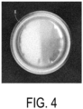
FIG. 4 is a bottom surface photograph of a known bottomed metal cylinder in the related art. -
FIG. 5 is a view illustrating an overview of a process for manufacturing the bottomed metal cylinder inFIG. 1 . -
FIG. 6 is a view illustrating a molding die used in a doming process inFIG. 5 . -
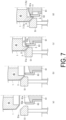
FIG. 7 is a view for describing the doming process ofFIG. 5 . - A bottomed metal cylinder according to the present invention is obtained by, for example, punching, drawing, and redrawing-ironing a thin element plate made of metal, then doming a bottom portion thereof and, lastly, subsequently performing post-processing such as washing and drying, outer surface printing, finishing varnish application and baking, inner surface coating application and baking, neck-in processing, and flange processing. The final form is typically, as a whole, as illustrated in
FIG. 1 . - With reference to
FIG. 1 , the bottomed metal cylinder according to the present invention denoted by 10 as a whole includes abody portion 1 provided with an outer surface having a straight cylindrical shape, aground contact portion 5 formed from a lower end of thebody portion 1 with achime portion 3, inclined inwardly, interposed therebetween, and a dome-shaped bottom surface 7 positioned in a region surrounded by theground contact portion 5. Further, an upper portion of thebody portion 1 extends to a neck-inportion 8 formed by post-processing, and a flange portion 9 is formed on an upper end of the neck-inportion 8. - The dome-
shaped bottom surface 7 is composed of aperipheral edge portion 7a extending to an upper end of a risingportion 6 rising inwardly from theground contact portion 5, and acenter portion 7b surrounded by theperipheral edge portion 7a. Theperipheral edge portion 7a corresponds to a portion with which a doming ring used at the time of doming described below comes into contact, and has a length of about 2 to 30 mm in a side cross-sectional view. Such a dome-shaped bottom surface 7 composed of theperipheral edge portion 7a and thecenter portion 7b has a large, substantially constant radius of curvature as a whole in a side cross-sectional view and, with formation of thebottom surface 7 in such a form at the bottom portion, it is possible to stably place this bottomedcylinder 10 and further increase a load strength thereof in an axial direction. - In the present invention, the metal constituting the bottomed
cylinder 10 described above is not particularly limited and may be various metals or alloys, but aluminum or an aluminum alloy is preferable from viewpoints such as weight reduction and thin-wall workability, and a seamless can coated on an inner surface with an organic resin is preferable from the viewpoint of taking advantage of the merits of the present invention. - With reference to
FIG. 1 as well as to an enlarged partial side cross-sectional view of the bottom portion inFIG. 2 and a bottom surface photograph inFIG. 3 , an important feature of the present invention is that anannular line 11 is observed at a boundary portion between theperipheral edge portion 7a and thecenter portion 7b of the dome-shaped bottom surface 7 described above. - That is, such a dome-
shaped bottom surface 7 is obtained by doming. However, in known bottomed metal cylinders in the related art, wrinkles X are present in a region corresponding to theperipheral edge portion 7a of the dome-shaped bottom surface 7 as illustrated in a bottom surface photograph inFIG. 4 . In the present invention, however, as is understood from the bottom surface photograph inFIG. 3 , theannular line 11 is formed instead of the wrinkles X. As understood from the fact that theperipheral edge portion 7a originates from the doming ring used in doming as described above, thisannular line 11 originates from an indentation of the doming ring, and a region outside and a region inside thisannular line 11 is theperipheral edge portion 7a and thecenter portion 7b, respectively. Further, a thickness t0 at thisannular line 11 originating from a local thin portion is a thickness reduced by about 3 to 5% relative to a thickness t1 at a position approximately 0.5 mm inward of theperipheral edge portion 7a, and the wrinkles X are eliminated by stretching. That is, in the present invention, theannular line 11 is formed instead of the wrinkles X. - In such a bottomed
metal cylinder 10, a thickness of the dome-shapedtop surface 7 at a center portion O typically corresponds to a thickness of the thin element material plate used for this molding, and a thickness of thebody portion 1 is determined in accordance with a degree of ironing (ironing rate). - For example, in the case of an aluminum seamless can used as a beverage can, a thickness of the element plate is about 0.180 to 0.350 mm, and a thickness of the thinnest area of the
body portion 1 is 30 to 50% of that of the element plate. - The bottomed
metal cylinder 10 according to the present invention having a form such as described above is manufactured by molding using the metal element plate described above (organic resin coating may be provided on the side corresponding to the inner surface). - As for the molding process using a metal element plate such as described above, the bottomed
cylinder 10 including the dome-shaped bottom surface 7 is obtained by punching, drawing, ironing, and doming as usual. - This process from punching to doming is illustrated in
FIG. 5 . - That is, as illustrated in
FIG. 5(a) , anelement plate 21 is punched by apunching punch 23 and apunching die 25 to obtain a circular plate 27 (punching process). Next, as illustrated inFIG. 5(b) , a drawn cup (bottomed cylinder) 35 is obtained by a drawing die 31 and a drawing punch 33 (drawing process). Here, the obtained drawncup 35 may be subjected to a doming process described below, but typically a re-drawing process and an ironing process are continuously performed as needed. - That is, as illustrated in
FIG. 5(c) , the drawncup 35 held in aredraw die 43 by apresser 41 is pushed downward using anironing punch 45, ironing is then performed through a plurality of ironing dies 47a to 47c, and subsequently doming is performed at the lowermost position. This doming is performed using a hold-down ring 51 and a doming die 61 described below. By this doming, the dome-shapedbottom surface 7 is formed simultaneously with thechime portion 3 and theground contact portion 5 described above. - After doming, a
stripper finger 53 is used to pull out the molded seamless can (bottomed metal cylinder) 10 from thepunch 45, thereby completing this process. Subsequent post-processing, such as washing and drying and neck-in processing, is then performed. - In an ironing process such as described above, although three ironing dies are disposed in
FIG. 5(c) and ironing is performed in three stages herein, the number of the ironing dies is not limited to three, and may be set to an appropriate number in accordance with a degree of intended thinning, and one die may be used for ironing in one stage, or two or more dies may be arranged for ironing in a plurality of stages. It is obvious that, in the case of a plurality of ironing dies being arranged in a processing direction and ironing being performed in a plurality stages, an inner diameter (working diameter) becomes smaller downstream in the processing direction. - In any case, after such ironing, doming is performed, forming the dome-shaped
bottom surface 7. - As illustrated in
FIG. 6 , the molding die used for doming includes the hold-down ring (annular holding die) 51 and adoming die 60, and doming is performed by a cooperative action of these molding dies and thepunch 45. In the present invention, the doming die 60 is divided into the base die 61 and adoming ring 63, and these are each provided independently vertically movable, which is an important feature. - That is, as understood from
FIG. 6 , in the hold-down ring (annular holding die) 51, a workingsurface 51a at an upper end is inclined inwardly downward, thechime portion 3 extending to the lower end of thebody portion 1 is formed by this workingsurface 51a, and theground contact surface 5 is formed at a lower end of the workingsurface 51a. - Further, the base die 61 is a die that defines the
center portion 7b of the dome-shapedbottom surface 7, and a workingsurface 61a at an upper end thereof is a surface that corresponds to thecenter portion 7b of the dome-shapedbottom surface 7. Further, thedoming ring 63 is a die that defines theperipheral edge portion 7a of the dome-shapedbottom surface 7, and a workingsurface 63a at an upper end thereof is a surface that corresponds to theperipheral edge portion 7a of the dome-shapedbottom surface 7. These workingsurfaces bottom surface 7. - As described above, the
peripheral edge portion 7a of the dome-shapedbottom surface 7 is a portion where wrinkles are likely to occur and, with the die surface defining this portion made separate from the die surface defining thecenter portion 7b, stresses applied to theperipheral edge portion 7a of the dome-shapedbottom surface 7 are concentrated, thereby stretching the wrinkles that would thereby occur, avoiding the occurrence of wrinkles, and causing theannular line 11 to appear at a position corresponding to an inner end portion of the workingsurface 63a of thedoming ring 63. That is, a length of this workingsurface 63a corresponds to a length of theperipheral edge portion 7a of the dome-shapedbottom surface 7 in a side cross-sectional view. - Doming using the molding die described above is carried out by the process illustrated in
FIG. 7 . - The hold-
down ring 51 is urged upward by air (not illustrated) and, in the initial stage, as illustrated inFIG. 7(a) , the workingsurface 63a of thedoming ring 63 is positioned downward of the workingsurface 51a of the hold-down ring 51, and the workingsurface 61a of the base die 61 is positioned further downward of the workingsurface 63a of thedoming ring 63. - When the
punch 45 is lowered in the state described above and thebody portion 1 of thecylinder 10 is pushed downward, a lower end portion of thebody portion 1 is pressed against the workingsurface 51a of the hold-down ring 51, forming thechime portion 3 at the lower end of thebody portion 1, as illustrated inFIG. 7(b) . - Next, when the
doming ring 63 is raised, theground contact portion 5 is defined, an inner side of theground contact portion 5 is pulled up, defining the risingportion 6, and the workingsurface 63a of thedoming ring 63 pushes up the surface inward of the risingportion 6, thereby defining theperipheral edge portion 7a of the dome-shapedbottom surface 7, as illustrated inFIG. 7(c) . - When the
peripheral edge portion 7a of the dome-shapedbottom surface 7 is formed as described above, as illustrated inFIG. 7(d) , the base die 61 is arranged after a delay and the workingsurface 61a thereof is pressed against the bottom portion of thecylinder 10, thereby forming thecenter portion 7b of the dome-shapedbottom surface 7, which defines the domed-shapedbottom surface 7 and, in the area corresponding to an end portion of the working surface of thedoming ring 63, theannular line 11 illustrated inFIGS. 2 and 3 , and the like is observed. Thus, the occurrence of wrinkles is effectively prevented by thedoming ring 63. - After doming is completed in this way, the
punch 45 is pulled out, the obtained molded body is separated from thepunch 45 by thestripper finger 53, and subsequent processes, such as washing, drying, neck-in processing, flange processing, and coating, are performed as described above to obtain a bottomed cylinder (seamless can) free of the occurrence of wrinkles on the bottom surface and having a high commercial value. -
- 1 Body portion
- 3 Chime portion
- 5 Ground contact portion
- 6 Rising portion
- 7 Dome-shaped bottom surface
- 7a Peripheral edge portion
- 7b Center portion
- 10 Bottomed cylinder
- 51 Hold-down ring (annular holding die)
- 60 Doming die
- 61 Base die
- 63 Doming ring
Claims (4)
- A bottomed metal cylinder comprising, at a bottom portion:a ground contact portion;a rising portion extending upward from an inner side of the ground contact portion; anda dome-shaped bottom surface extending to the rising portion, whereinan annular line is observed at a peripheral edge portion of the dome-shaped bottom surface.
- The bottomed metal cylinder according to claim 1, wherein
the bottomed metal cylinder is an aluminum seamless can. - A molding die used for dome-molding a bottom portion of a bottomed metal cylinder, the molding die comprising:an annular holding die for holding a bottom portion peripheral edge of the bottomed metal cylinder; anda doming die for defining a dome-shaped bottom surface, whereinthe doming die is divided intoa doming ring for defining a peripheral edge portion of the dome-shaped bottom surface, anda base die for defining a center portion of the dome-shaped bottom surface inward of the peripheral edge portion, andthe doming ring and the base die are each independently vertically movable.
- A method for dome-molding a bottom portion of a bottomed metal cylinder, the method comprising:preparing the molding die according to claim 3;lowering a punch sleeve from inside the bottomed metal cylinder and pressing a lower end peripheral edge portion of the cylinder against a working surface of the annular holding die, to form a chime portion and a ground contact portion at a bottom surface peripheral edge portion of the cylinder;raising the doming ring while holding the chime portion and the ground contact portion of the cylinder by the punch sleeve and the working surface of the annular holding die to form a rising portion and a peripheral edge portion of a dome-shaped bottom surface inside the ground contact portion; andarranging a base die to form a center portion of the dome-shaped bottom surface.
Applications Claiming Priority (2)
| Application Number | Priority Date | Filing Date | Title |
|---|---|---|---|
| JP2022062300A JP2023152358A (en) | 2022-04-04 | 2022-04-04 | Metal cylinder with bottom |
| PCT/JP2023/003216 WO2023195220A1 (en) | 2022-04-04 | 2023-02-01 | Bottomed metal cylinder |
Publications (2)
| Publication Number | Publication Date |
|---|---|
| EP4506081A1 true EP4506081A1 (en) | 2025-02-12 |
| EP4506081A4 EP4506081A4 (en) | 2026-07-08 |
Family
ID=88242781
Family Applications (1)
| Application Number | Title | Priority Date | Filing Date |
|---|---|---|---|
| EP23784515.1A Pending EP4506081A4 (en) | 2022-04-04 | 2023-02-01 | METAL CYLINDER WITH A END |
Country Status (6)
| Country | Link |
|---|---|
| US (1) | US20250026526A1 (en) |
| EP (1) | EP4506081A4 (en) |
| JP (1) | JP2023152358A (en) |
| CN (1) | CN118900807A (en) |
| TW (1) | TW202402629A (en) |
| WO (1) | WO2023195220A1 (en) |
Family Cites Families (13)
| Publication number | Priority date | Publication date | Assignee | Title |
|---|---|---|---|---|
| GB2119743B (en) * | 1982-04-19 | 1986-02-12 | American Can Co | Buckle-resistant cans and a method of making them |
| EP0196327A4 (en) * | 1984-10-03 | 1988-06-27 | Nat Can Corp | Domer assembly for forming container end wall. |
| US4723433A (en) * | 1986-01-28 | 1988-02-09 | Adolph Coors Company | Method and apparatus for doming can bottoms |
| US4790169A (en) * | 1986-01-28 | 1988-12-13 | Adolph Coors Company | Apparatus for doming can bottoms |
| JPH0675737B2 (en) * | 1989-06-27 | 1994-09-28 | 東洋製罐株式会社 | Molding method for can bodies for two-piece cans |
| JPH0796138B2 (en) * | 1991-06-19 | 1995-10-18 | 東洋製罐株式会社 | Seamless can manufacturing method |
| JPH11104764A (en) * | 1997-09-30 | 1999-04-20 | Mitsubishi Materials Corp | Can manufacturing method and can manufacturing apparatus |
| JP4112137B2 (en) * | 1998-11-20 | 2008-07-02 | ユニバーサル製缶株式会社 | Can and manufacturing method thereof |
| JP2009078303A (en) * | 2009-01-21 | 2009-04-16 | Toyo Seikan Kaisha Ltd | Apparatus for manufacturing resin coated metallic seamless can body |
| US10525519B2 (en) * | 2009-10-21 | 2020-01-07 | Stolle Machinery Company, Llc | Container, and selectively formed cup, tooling and associated method for providing same |
| DE102015215590A1 (en) * | 2015-08-14 | 2017-02-16 | Ball Europe Gmbh | Cans for beverage cans |
| JP6977302B2 (en) * | 2017-04-12 | 2021-12-08 | 東洋製罐株式会社 | Aluminum seamless can |
| RU2019137481A (en) * | 2017-04-21 | 2021-05-21 | КЕН ФОРМИНГ ТЕКНОЛОДЖИС, ЭлЭлСи | LIGHTWEIGHT CONTAINER ARCH PROFILE AND ITS MANUFACTURING METHOD |
-
2022
- 2022-04-04 JP JP2022062300A patent/JP2023152358A/en active Pending
-
2023
- 2023-02-01 WO PCT/JP2023/003216 patent/WO2023195220A1/en not_active Ceased
- 2023-02-01 EP EP23784515.1A patent/EP4506081A4/en active Pending
- 2023-02-01 CN CN202380028603.XA patent/CN118900807A/en active Pending
- 2023-03-15 TW TW112109479A patent/TW202402629A/en unknown
-
2024
- 2024-10-03 US US18/905,314 patent/US20250026526A1/en active Pending
Also Published As
| Publication number | Publication date |
|---|---|
| TW202402629A (en) | 2024-01-16 |
| CN118900807A (en) | 2024-11-05 |
| EP4506081A4 (en) | 2026-07-08 |
| US20250026526A1 (en) | 2025-01-23 |
| JP2023152358A (en) | 2023-10-17 |
| WO2023195220A1 (en) | 2023-10-12 |
Similar Documents
| Publication | Publication Date | Title |
|---|---|---|
| EP2739412B1 (en) | Can manufacture | |
| JP3621129B2 (en) | Method for forming metal container body | |
| CN102858643B (en) | Can body | |
| CN104302420B (en) | Vessel, selectively formed shell, tooling for providing shell, and related methods | |
| WO2000010751A1 (en) | Method and apparatus for forming a can end having an anti-peaking bead | |
| US6290447B1 (en) | Single station blanked, formed and curled can end with outward formed curl | |
| CN110099760B (en) | Method and apparatus for forming a seamed can end | |
| JP2013523460A5 (en) | ||
| JP5908762B2 (en) | Cage manufacturing method and cage | |
| CN118891114A (en) | Method for manufacturing a conical metal object made of sheet metal | |
| CN115740205A (en) | Continuous stamping method for manufacturing thin-wall conical barrel part | |
| JP6977302B2 (en) | Aluminum seamless can | |
| US20250026526A1 (en) | Bottomed metal cylinder | |
| JPH04274834A (en) | Method and device for forming single body type rivet on end of container | |
| CN114007776A (en) | A method for forming a deep drawn closure cap | |
| US20230256500A1 (en) | Can lid and manufacturing method therefor | |
| JP2025062937A (en) | Seamless Metal Can | |
| GB2092932A (en) | Improved tooling for making container bodies | |
| WO2025074752A1 (en) | Seamless metal can | |
| JP2025064600A (en) | Ultra-light seamless aluminum can | |
| RU2791478C1 (en) | Method for producing thin-walled spherical shells | |
| JP2000254735A (en) | Press forming method of cup-shaped molded product by progressive press | |
| JP2013223878A (en) | Method for manufacturing beverage can |
Legal Events
| Date | Code | Title | Description |
|---|---|---|---|
| STAA | Information on the status of an ep patent application or granted ep patent |
Free format text: STATUS: THE INTERNATIONAL PUBLICATION HAS BEEN MADE |
|
| PUAI | Public reference made under article 153(3) epc to a published international application that has entered the european phase |
Free format text: ORIGINAL CODE: 0009012 |
|
| STAA | Information on the status of an ep patent application or granted ep patent |
Free format text: STATUS: REQUEST FOR EXAMINATION WAS MADE |
|
| 17P | Request for examination filed |
Effective date: 20240917 |
|
| AK | Designated contracting states |
Kind code of ref document: A1 Designated state(s): AL AT BE BG CH CY CZ DE DK EE ES FI FR GB GR HR HU IE IS IT LI LT LU LV MC ME MK MT NL NO PL PT RO RS SE SI SK SM TR |
|
| DAV | Request for validation of the european patent (deleted) | ||
| DAX | Request for extension of the european patent (deleted) | ||
| RIC1 | Information provided on ipc code assigned before grant |
Ipc: B21D 22/28 20060101AFI20260313BHEP Ipc: B21D 22/30 20060101ALI20260313BHEP Ipc: B21D 24/00 20060101ALI20260313BHEP Ipc: B21D 51/26 20060101ALI20260313BHEP Ipc: B65D 1/16 20060101ALI20260313BHEP |
|
| A4 | Supplementary search report drawn up and despatched |
Effective date: 20260610 |
|
| RIC1 | Information provided on ipc code assigned before grant |
Ipc: B21D 22/28 20060101AFI20260603BHEP Ipc: B21D 22/30 20060101ALI20260603BHEP Ipc: B21D 24/00 20060101ALI20260603BHEP Ipc: B21D 51/26 20060101ALI20260603BHEP Ipc: B65D 1/16 20060101ALI20260603BHEP |