EP4506058A1 - Aromatic compound reactor - Google Patents
Aromatic compound reactor Download PDFInfo
- Publication number
- EP4506058A1 EP4506058A1 EP23781373.8A EP23781373A EP4506058A1 EP 4506058 A1 EP4506058 A1 EP 4506058A1 EP 23781373 A EP23781373 A EP 23781373A EP 4506058 A1 EP4506058 A1 EP 4506058A1
- Authority
- EP
- European Patent Office
- Prior art keywords
- reactor
- reactant
- reaction solution
- aromatic compound
- mixing member
- Prior art date
- Legal status (The legal status is an assumption and is not a legal conclusion. Google has not performed a legal analysis and makes no representation as to the accuracy of the status listed.)
- Pending
Links
Images


Classifications
-
- B—PERFORMING OPERATIONS; TRANSPORTING
- B01—PHYSICAL OR CHEMICAL PROCESSES OR APPARATUS IN GENERAL
- B01J—CHEMICAL OR PHYSICAL PROCESSES, e.g. CATALYSIS OR COLLOID CHEMISTRY; THEIR RELEVANT APPARATUS
- B01J4/00—Feed or outlet devices; Feed or outlet control devices
- B01J4/001—Feed or outlet devices as such, e.g. feeding tubes
- B01J4/002—Nozzle-type elements
-
- B—PERFORMING OPERATIONS; TRANSPORTING
- B01—PHYSICAL OR CHEMICAL PROCESSES OR APPARATUS IN GENERAL
- B01J—CHEMICAL OR PHYSICAL PROCESSES, e.g. CATALYSIS OR COLLOID CHEMISTRY; THEIR RELEVANT APPARATUS
- B01J19/00—Chemical, physical or physico-chemical processes in general; Their relevant apparatus
-
- B—PERFORMING OPERATIONS; TRANSPORTING
- B01—PHYSICAL OR CHEMICAL PROCESSES OR APPARATUS IN GENERAL
- B01J—CHEMICAL OR PHYSICAL PROCESSES, e.g. CATALYSIS OR COLLOID CHEMISTRY; THEIR RELEVANT APPARATUS
- B01J19/00—Chemical, physical or physico-chemical processes in general; Their relevant apparatus
- B01J19/0053—Details of the reactor
- B01J19/0066—Stirrers
-
- B—PERFORMING OPERATIONS; TRANSPORTING
- B01—PHYSICAL OR CHEMICAL PROCESSES OR APPARATUS IN GENERAL
- B01J—CHEMICAL OR PHYSICAL PROCESSES, e.g. CATALYSIS OR COLLOID CHEMISTRY; THEIR RELEVANT APPARATUS
- B01J19/00—Chemical, physical or physico-chemical processes in general; Their relevant apparatus
- B01J19/18—Stationary reactors having moving elements inside
- B01J19/1806—Stationary reactors having moving elements inside resulting in a turbulent flow of the reactants, such as in centrifugal-type reactors, or having a high Reynolds-number
-
- B—PERFORMING OPERATIONS; TRANSPORTING
- B01—PHYSICAL OR CHEMICAL PROCESSES OR APPARATUS IN GENERAL
- B01J—CHEMICAL OR PHYSICAL PROCESSES, e.g. CATALYSIS OR COLLOID CHEMISTRY; THEIR RELEVANT APPARATUS
- B01J4/00—Feed or outlet devices; Feed or outlet control devices
-
- B—PERFORMING OPERATIONS; TRANSPORTING
- B01—PHYSICAL OR CHEMICAL PROCESSES OR APPARATUS IN GENERAL
- B01J—CHEMICAL OR PHYSICAL PROCESSES, e.g. CATALYSIS OR COLLOID CHEMISTRY; THEIR RELEVANT APPARATUS
- B01J2204/00—Aspects relating to feed or outlet devices; Regulating devices for feed or outlet devices
- B01J2204/002—Aspects relating to feed or outlet devices; Regulating devices for feed or outlet devices the feeding side being of particular interest
Definitions
- the present invention relates to a device for improving the reactivity of an aromatic compound, and more particularly, to an aromatic compound reactor capable of increasing the mixing efficiency of reactants and improving the selectivity of reactants.
- Toluene a type of aromatic compound, may have a chlorination reaction through a reaction with chlorine to be manufactured into o-chlorotoluene and p-chlorotoluene.
- gaseous chlorine is injected through a sparger disposed inside the reactor, and a portion of a reaction solution including toluene is injected through a nozzle at the bottom of the reactor to cause a reaction.
- the reactor having such a structure has a problem in that a channeling phenomenon occurs while the reaction solution including toluene, an aromatic compound, reacts with chlorine, or the mixing degree between substances deteriorates significantly, thereby lowering the efficiency of the reaction.
- An object of the present invention is to provide an aromatic compound reactor including a mixing member mounted therein so that a reactant may be evenly distributed, rather than supplying the reactant through a nozzle at the bottom of the aromatic compound reactor of the related art.
- an aromatic compound reactor includes: a reactor having a reaction space formed therein; a plurality of reactant distributors disposed to be spaced apart from each other in a lower portion of the reactor and formed as a flow path to supply a reactant to the reaction space through both ends thereof; at least one reaction solution injection portion formed as a through-hole between the plurality of reactant distributor and supplying a reaction solution to the reaction space; and a mixing member provided in the reaction solution injection portion and dispersing the reaction solution in the reaction space using a rotational flow induced therein.
- an average flow rate of the reactant injected into the reactor may be increased, thereby minimizing back mixing of the reactant.
- the flow rate of the reactant may be strengthened, thereby improving the mixing degree between substances and increasing the mixing efficiency between reactants.
- an unreacted section at the bottom of the reactor may be weakened, thereby improving the selectivity of the reactant.
- an aromatic compound reactor of the present invention includes a reactor 100 having a reaction space formed therein; a plurality of reactant distributors 200 disposed to be spaced apart from each other in a lower portion of the reactor 100 and formed as a flow path to supply a reactant to the reaction space through both ends thereof; at least one reaction solution injection portion 300 formed as a through-hole between the plurality of reactant distributors 200 and supplying a reaction solution to the reaction space; and a mixing member 400 provided in the reaction solution injection portion 300 and dispersing the reaction solution in the reaction space using a rotational flow induced therein.
- reaction solution supplied to the reaction solution injection portion and the reactant of the reactant distributor may be dispersed by the mixing member.
- the reactant supplied to the reactant distributor 200 may be a gas or a liquid.
- the mixing member 400 may be formed such that a distance from a lower bottom surface of the reactor 100 to a lower bottom surface of the mixing member 400 is within a range of 0.008 to 0.02h when a height of the reactor 100 is h.
- the reactant distributor 200 may be formed such that a distance from an upper portion of the mixing member 400 to the center of the reactant distributor 200 is within a range of 0.1 to 0.4h when the height of the reactor 100 is h.
- the mixing member 400 may include: a hub 410 coupled to the center of the mixing member 400; a fan 420 including a plurality of blades 421 formed on an outer circumferential surface of the hub 410; a circumferential portion 430 surrounding an outer circumferential portion 430 of the fan 420; and an impact portion 440 formed at the center of the circumferential portion 430 and with which the injected reaction solution collides.
- the blade 421 may be configured so that a reaction solution injected from the reaction solution injection portion 300 and colliding with the impact portion 440 may be dispersed in the reaction space by a rotational flow by the blade 421.
- a thickness of the blade 421 may be 0.6 to 1.0t when a thickness of the mixing member 400 is t.
- reaction solution injection portion 300 may be connected to an external reaction solution supply portion in the form of a nozzle.
- the plurality of reactant distributors 200 may be connected to an external reactant liquid supply portion.
- the present invention relates to an aromatic compound reactor, and the present invention will be described in detail through the accompanying drawings and examples and comparative examples.
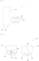
- FIG. 1 is a schematic diagram 1 illustrating a front view and a bottom view of the aromatic compound reactor of the related art.
- a mixing member 400 is configured above a nozzle at the bottom of the reactor 100, and through optimization design, the mixing member 400 is configured to reduce the channeling phenomenon inside the reactor 100 and increase an average flow rate to minimize back mixing in the reactor 100.
- FIG. 2 is a schematic diagram 1000 illustrating a side view and a bottom view of an aromatic compound reactor of the present invention.
- the reactor 100 may have a reaction space formed therein.
- a plurality of reactant distributors 200 may be formed to be spaced apart from each other in a lower portion of the reactor 100 and formed in a flow path shape so that reactants may be supplied to the reaction space through both ends.
- the plurality of reactant distributors 200 may be connected to an external reactant supply unit.
- the reactant distributor 200 may be formed such that the distance from the top of the mixing member 400 to the center of the reactant distributor 200 is within a range of 0.1 to 0.4 h.
- At least one reaction solution injection portion 300 may be disposed between the plurality of the reactant distributors 200 and may supply a reaction solution to the reaction space.
- reaction solution injection portion 300 may be connected to an external reaction solution supply unit in the form of a nozzle.
- the mixing member 400 may be provided in the reaction solution injection portion 300, and the reaction solution may be dispersed in the reaction space by using a rotational flow formed by the blade 421 provided in the mixing member 400.
- the aromatic compound reactor 100 having such a structure has the effect that the reaction solution supplied to the reaction solution injection portion 300 and the reactant of the reactant distributor 200 may be dispersed in the reaction space by the rotational flow by the blade 421 provided in the mixing member 400.
- reaction solution supplied to the reaction solution injection portion 300 and the reactant of the reactant distributor 200 may be dispersed by the mixing member 400, so that the reaction solution may be dispersed.
- the reactant supplied to the reactant distributor 200 may be supplied in the form of a gas or a liquid.
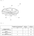
- FIG. 3 illustrates a shape and structure of the mixing member installed in the aromatic compound reactor according to Example 2 of the present invention.
- the hub 410 may be coupled to the center of the mixing member 400.
- the fan 420 may include a plurality of blades 421 formed on the outer circumferential surface of the hub.
- an outer side of the fan 420 may be surrounded by the circumferential portion 430.
- the impact portion 440 is formed at the center of the circumferential portion 430, so that the injected reaction solution may collide therewith, thereby dispersing the reactant.
- the blade 421 may be disposed toward the bottom of the reaction solution injection portion 300. Therefore, the reaction solution injected from the reaction solution injection portion 300 may collide with the impact portion 440 to be dispersed by the rotational flow by the blade 421.
- the thickness of the blade 421 may be 0.6 to 1.0t when the thickness of the mixing member is t.
- the mixing member may be formed such that the distance from the lower bottom surface of the reactor 100 to the lower bottom surface of the mixing member 400 is within a range of 0.008 to 0.02h when the height of the reactor is h.
- FIG. 4 is a table illustrating the effect of dispersing a flow direction and increasing a linear velocity of toluene introduced from the bottom of the reactor by installing the mixing member 400 of the present invention and the effect of improving the catalyst mixing degree accordingly.
- the reaction solution was injected through the nozzle of the reaction solution injection portion 300.
- the reaction solution was injected by mounting the mixing member 400 without the blade 421 at an upper portion thereof on the reaction solution injection portion 300.
- the arrangement distance from the bottom of the reactor to the top of the mixing member 400 was 35 mm, and the height of the mixing member 400 was 5 mm.
- the reaction solution was injected by mounting the mixing member 400 with the blade 421 formed on the outer circumferential surface of the hub 410 on the reaction solution injection portion 300.
- the arrangement distance from the bottom of the reactor to the top of the mixing member 400 was 35 mm, and the height of the mixing member 400 was 5 mm.
- Comparative Example 1 had 100% of unreacted catalyst, indicating that no reaction occurred at all, Example 1 had 89.2%, and Example 2 had 87.4%, indicating that the unreacted catalyst amount of Example 2 was significantly reduced compared to Comparative Example 1 and Example 1.
- FIG. 5 is a table illustrating a simulation of an unreacted section at the bottom of the reactor of the present invention, illustrating a simulation of the unreacted section at the bottom of the reactor through a flow analysis (CFD) .
- CFD flow analysis
- the mixing member 400 including a plurality of blades 421 may be included, and the arrangement distance from the bottom of the reactor to the top of the mixing member 400 was 35 mm, and the height of the mixing member 400 was 5 mm.
- the flow model used in the analysis used the mixing member 400 including nine blades 421, and a section in which the actual chlorination reaction occurs is expected to be a section of 30 to 70 cm above the reactant distributor 200, so in the simulation of the present invention, the section up to 30 cm from the tangent of the reactor was set as the analysis section.
- iron chloride (FeCl 3 ) is dissolved in toluene and does not precipitate in a solid state, but in order to identify the unreacted section in the flow analysis, a flow analysis was conducted by performing a simulation based on the assumption that iron chloride (FeCl 3 ) precipitates in a solid state.
- the structure of the mixing member 400 was designed so that the flow in the lower portion of the reactor can be dispersed, and in order to additionally conduct a detailed simulation therefor, the mixing member 400 that does not include the blade 421 and the mixing member 400 that includes a plurality of blades 421 were designed and an example was conducted.
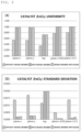
- FIG. 6(a) is a graph illustrating the uniformity of a catalyst (FeCl 3 ) of the present invention
- FIG. 6(b) is a graph illustrating a standard deviation of the catalyst (FeCl 3 ) of the present invention.
- FIG. 6(a) and FIG. 6(b) when the uniformity of distribution of iron chloride (FeCl 3 ) was compared by designating five planes in a height direction of the reactor, it was confirmed that the uniformity of catalyst dispersion was also improved by 20% or more.
- the mixing member 400 including a plurality of or more blades 421 was confirmed as an improvement plan and additional simulation was conducted.
- FIG. 7 is a table illustrating a simulation of the catalyst deposition phenomenon of the present invention, illustrating a simulation of the catalyst deposition phenomenon at the bottom of the reactor through a flow analysis (CFD).
- CFD flow analysis
- the catalyst was set as particles with a certain diameter and the simulation was performed using a two-phase analysis.
- the catalyst is dissolved in the actual reaction and is in one phase, but it was configured as two phases for performing the simulation and analysis.
- the mixing member 400 that does not include the blade 421 was simulated such that the introduced iron chloride (FeCl 3 ) catalyst flows upward in a strong flow formed along the flow of toluene toward the center of the reactor, is then transferred from the upper portion of the reactor to a wall side flow, and is mostly deposited at the bottom of the reactor and the upper portion of the reactant distributor.
- FeCl 3 iron chloride
- the improvement through the configuration of the mixing member 400 that includes a plurality of blades 421 was simulated such that the iron chloride (FeCl 3 ) catalyst formed an even flow with toluene inside the reactor without a deposited form due to the dispersion effect of the flow at the bottom of the reactor, and thus, it can be seen that the amount of unreacted catalyst was improved.
- FeCl 3 iron chloride
- the aromatic compound reactor of the present invention provides a technology that may increase the mixing efficiency of the reactant, increase the selectivity of the reactants, and reduce the amount of catalyst deposition added to the reactant by installing the mixing member inside the aromatic compound reactor so that the reactant may be evenly dispersed, thereby improving the productivity and yield of the reactant.
Landscapes
- Chemical & Material Sciences (AREA)
- Chemical Kinetics & Catalysis (AREA)
- Organic Chemistry (AREA)
- Organic Low-Molecular-Weight Compounds And Preparation Thereof (AREA)
- Physical Or Chemical Processes And Apparatus (AREA)
Abstract
Description
- The present invention relates to a device for improving the reactivity of an aromatic compound, and more particularly, to an aromatic compound reactor capable of increasing the mixing efficiency of reactants and improving the selectivity of reactants.
- Toluene, a type of aromatic compound, may have a chlorination reaction through a reaction with chlorine to be manufactured into o-chlorotoluene and p-chlorotoluene.
- In a reactor in which the chlorination reaction takes place, gaseous chlorine is injected through a sparger disposed inside the reactor, and a portion of a reaction solution including toluene is injected through a nozzle at the bottom of the reactor to cause a reaction.
- The reactor having such a structure has a problem in that a channeling phenomenon occurs while the reaction solution including toluene, an aromatic compound, reacts with chlorine, or the mixing degree between substances deteriorates significantly, thereby lowering the efficiency of the reaction.
- In the
Korean Application Publication No. 10-1196278 - An object of the present invention is to provide an aromatic compound reactor including a mixing member mounted therein so that a reactant may be evenly distributed, rather than supplying the reactant through a nozzle at the bottom of the aromatic compound reactor of the related art.
- In one general aspect, an aromatic compound reactor includes: a reactor having a reaction space formed therein; a plurality of reactant distributors disposed to be spaced apart from each other in a lower portion of the reactor and formed as a flow path to supply a reactant to the reaction space through both ends thereof; at least one reaction solution injection portion formed as a through-hole between the plurality of reactant distributor and supplying a reaction solution to the reaction space; and a mixing member provided in the reaction solution injection portion and dispersing the reaction solution in the reaction space using a rotational flow induced therein.
- According to the present invention, by configuring the mixing member in the reactor, an average flow rate of the reactant injected into the reactor may be increased, thereby minimizing back mixing of the reactant.
- In addition, by configuring the mixing member in the reactor, the flow rate of the reactant may be strengthened, thereby improving the mixing degree between substances and increasing the mixing efficiency between reactants.
- In addition, by configuring the mixing member in the reactor, an unreacted section at the bottom of the reactor may be weakened, thereby improving the selectivity of the reactant.
-
-
FIG. 1 is a schematic diagram illustrating a front view and a bottom view of an aromatic compound reactor of the related art. -
FIG. 2 is a schematic diagram illustrating a side view and a bottom view of an aromatic compound reactor of the present invention. -
FIG. 3 illustrates a shape and structure of a mixing member installed in an aromatic compound reactor according to Example 2 of the present invention. -
FIG. 4 is a table illustrating the effect of dispersing a flow direction and increasing a linear velocity of toluene introduced from the bottom of the reactor by installing a mixing member of the present invention and the effect of improving the catalyst mixing degree accordingly. -
FIG. 5 is a table illustrating a simulation of an unreacted section at the bottom of the reactor of the present invention. -
FIG. 6(a) is a graph illustrating the uniformity of a catalyst (FeCl3) of the present invention. -
FIG. 6(b) is a graph illustrating a standard deviation of the catalyst (FeCl3) of the present invention. -
FIG. 7 is a table illustrating the simulation of a catalyst deposition phenomenon of the present invention. - In order to achieve the purpose, an aromatic compound reactor of the present invention includes a
reactor 100 having a reaction space formed therein; a plurality ofreactant distributors 200 disposed to be spaced apart from each other in a lower portion of thereactor 100 and formed as a flow path to supply a reactant to the reaction space through both ends thereof; at least one reactionsolution injection portion 300 formed as a through-hole between the plurality ofreactant distributors 200 and supplying a reaction solution to the reaction space; and amixing member 400 provided in the reactionsolution injection portion 300 and dispersing the reaction solution in the reaction space using a rotational flow induced therein. - In addition, in the aromatic compound reactor, the reaction solution supplied to the reaction solution injection portion and the reactant of the reactant distributor may be dispersed by the mixing member.
- In addition, the reactant supplied to the
reactant distributor 200 may be a gas or a liquid. - In addition, the
mixing member 400 may be formed such that a distance from a lower bottom surface of thereactor 100 to a lower bottom surface of themixing member 400 is within a range of 0.008 to 0.02h when a height of thereactor 100 is h. - In addition, the
reactant distributor 200 may be formed such that a distance from an upper portion of themixing member 400 to the center of thereactant distributor 200 is within a range of 0.1 to 0.4h when the height of thereactor 100 is h. - In addition, the
mixing member 400 may include: ahub 410 coupled to the center of themixing member 400; afan 420 including a plurality ofblades 421 formed on an outer circumferential surface of thehub 410; acircumferential portion 430 surrounding an outercircumferential portion 430 of thefan 420; and animpact portion 440 formed at the center of thecircumferential portion 430 and with which the injected reaction solution collides. - In addition, the
blade 421 may be configured so that a reaction solution injected from the reactionsolution injection portion 300 and colliding with theimpact portion 440 may be dispersed in the reaction space by a rotational flow by theblade 421. - In addition, a thickness of the
blade 421 may be 0.6 to 1.0t when a thickness of themixing member 400 is t. - In addition, the reaction
solution injection portion 300 may be connected to an external reaction solution supply portion in the form of a nozzle. - In addition, the plurality of
reactant distributors 200 may be connected to an external reactant liquid supply portion. - The present invention relates to an aromatic compound reactor, and the present invention will be described in detail through the accompanying drawings and examples and comparative examples.
-
FIG. 1 is a schematic diagram 1 illustrating a front view and a bottom view of the aromatic compound reactor of the related art. - As shown in
FIG. 1 , in the aromatic compound reactor of the related art, a portion of a reaction solution including an aromatic compound was injected through a nozzle at the bottom of the reactor. However, there was a problem that the reaction solution was not mixed with a reaction gas and exhibited a channeling phenomenon, which significantly worsened the mixing degree between materials. - Therefore, in the present invention, as shown in
FIG. 2 , amixing member 400 is configured above a nozzle at the bottom of thereactor 100, and through optimization design, themixing member 400 is configured to reduce the channeling phenomenon inside thereactor 100 and increase an average flow rate to minimize back mixing in thereactor 100. -
FIG. 2 is a schematic diagram 1000 illustrating a side view and a bottom view of an aromatic compound reactor of the present invention. - The
reactor 100 may have a reaction space formed therein. - In addition, a plurality of
reactant distributors 200 may be formed to be spaced apart from each other in a lower portion of thereactor 100 and formed in a flow path shape so that reactants may be supplied to the reaction space through both ends. - Here, the plurality of
reactant distributors 200 may be connected to an external reactant supply unit. - In addition, here, when the height of the
reactor 100 is h, thereactant distributor 200 may be formed such that the distance from the top of themixing member 400 to the center of thereactant distributor 200 is within a range of 0.1 to 0.4 h. - In addition, at least one reaction
solution injection portion 300 may be disposed between the plurality of thereactant distributors 200 and may supply a reaction solution to the reaction space. - Here, the reaction
solution injection portion 300 may be connected to an external reaction solution supply unit in the form of a nozzle. - In addition, the
mixing member 400 may be provided in the reactionsolution injection portion 300, and the reaction solution may be dispersed in the reaction space by using a rotational flow formed by theblade 421 provided in themixing member 400. - Therefore, the
aromatic compound reactor 100 having such a structure has the effect that the reaction solution supplied to the reactionsolution injection portion 300 and the reactant of thereactant distributor 200 may be dispersed in the reaction space by the rotational flow by theblade 421 provided in themixing member 400. - In addition, the reaction solution supplied to the reaction
solution injection portion 300 and the reactant of thereactant distributor 200 may be dispersed by themixing member 400, so that the reaction solution may be dispersed. - At this time, the reactant supplied to the
reactant distributor 200 may be supplied in the form of a gas or a liquid. -
FIG. 3 illustrates a shape and structure of the mixing member installed in the aromatic compound reactor according to Example 2 of the present invention. - The
hub 410 may be coupled to the center of themixing member 400. - The
fan 420 may include a plurality ofblades 421 formed on the outer circumferential surface of the hub. - In addition, an outer side of the
fan 420 may be surrounded by thecircumferential portion 430. - The
impact portion 440 is formed at the center of thecircumferential portion 430, so that the injected reaction solution may collide therewith, thereby dispersing the reactant. - In addition, the
blade 421 may be disposed toward the bottom of the reactionsolution injection portion 300. Therefore, the reaction solution injected from the reactionsolution injection portion 300 may collide with theimpact portion 440 to be dispersed by the rotational flow by theblade 421. - In addition, here, the thickness of the
blade 421 may be 0.6 to 1.0t when the thickness of the mixing member is t. - In addition, here, the mixing member may be formed such that the distance from the lower bottom surface of the
reactor 100 to the lower bottom surface of themixing member 400 is within a range of 0.008 to 0.02h when the height of the reactor is h. -
FIG. 4 is a table illustrating the effect of dispersing a flow direction and increasing a linear velocity of toluene introduced from the bottom of the reactor by installing themixing member 400 of the present invention and the effect of improving the catalyst mixing degree accordingly. - As shown in
FIG. 4 , the results of the unreacted catalyst amount according to the arrangement length from the bottom of the reactor to the top of themixing member 400 and the height of themixing member 400 of a comparative example and experimental examples are shown. - The reaction solution was injected through the nozzle of the reaction
solution injection portion 300. - The reaction solution was injected by mounting the mixing
member 400 without theblade 421 at an upper portion thereof on the reactionsolution injection portion 300. - In addition, the arrangement distance from the bottom of the reactor to the top of the mixing
member 400 was 35 mm, and the height of the mixingmember 400 was 5 mm. - The reaction solution was injected by mounting the mixing
member 400 with theblade 421 formed on the outer circumferential surface of thehub 410 on the reactionsolution injection portion 300. - In addition, the arrangement distance from the bottom of the reactor to the top of the mixing
member 400 was 35 mm, and the height of the mixingmember 400 was 5 mm. - As shown in
FIG. 4 , it can be seen that Comparative Example 1 had 100% of unreacted catalyst, indicating that no reaction occurred at all, Example 1 had 89.2%, and Example 2 had 87.4%, indicating that the unreacted catalyst amount of Example 2 was significantly reduced compared to Comparative Example 1 and Example 1. -
FIG. 5 is a table illustrating a simulation of an unreacted section at the bottom of the reactor of the present invention, illustrating a simulation of the unreacted section at the bottom of the reactor through a flow analysis (CFD) . - In the simulation of the unreacted section at the bottom of the reactor of
FIG. 5 , the mixingmember 400 including a plurality ofblades 421 may be included, and the arrangement distance from the bottom of the reactor to the top of the mixingmember 400 was 35 mm, and the height of the mixingmember 400 was 5 mm. - In general, an experiment of a reaction of aromatic compounds is conducted in two phases of toluene and chlorine gas, but in the present invention, a flow analysis was conducted through simulation by changing to one phase for detailed simulation of the lower portion of the reactor.
- The flow model used in the analysis used the mixing
member 400 including nineblades 421, and a section in which the actual chlorination reaction occurs is expected to be a section of 30 to 70 cm above thereactant distributor 200, so in the simulation of the present invention, the section up to 30 cm from the tangent of the reactor was set as the analysis section. - In the analysis model of the lower portion of the reactor, a form in which toluene and the catalyst iron chloride (FeCl3) were introduced from the nozzle of the reaction
solution injection portion 300 and were mixed and settled at the bottom of the lower portion of the reactor was simulated. - In reality, iron chloride (FeCl3) is dissolved in toluene and does not precipitate in a solid state, but in order to identify the unreacted section in the flow analysis, a flow analysis was conducted by performing a simulation based on the assumption that iron chloride (FeCl3) precipitates in a solid state.
- As shown in the comparative example of
FIG. 5 , it can be seen that a channeling phenomenon was confirmed in the existing reactor. - In order to improve this channeling phenomenon, the structure of the mixing
member 400 was designed so that the flow in the lower portion of the reactor can be dispersed, and in order to additionally conduct a detailed simulation therefor, the mixingmember 400 that does not include theblade 421 and the mixingmember 400 that includes a plurality ofblades 421 were designed and an example was conducted. - As shown in Examples 1 and 2 of
FIG. 5 , it can be seen that the channeling phenomenon was completely resolved when compared to the existing reactor regardless of the shape of the mixingmember 400. This phenomenon may be determined to be due to the influence of the dispersion effect of the flow in the lower portion of the reactor according to a result of the velocity vector analysis. - In addition,
FIG. 6(a) is a graph illustrating the uniformity of a catalyst (FeCl3) of the present invention, andFIG. 6(b) is a graph illustrating a standard deviation of the catalyst (FeCl3) of the present invention. As shown inFIG. 6(a) and FIG. 6(b) , when the uniformity of distribution of iron chloride (FeCl3) was compared by designating five planes in a height direction of the reactor, it was confirmed that the uniformity of catalyst dispersion was also improved by 20% or more. - In addition, depending on the shape of the mixing
member 400, in the case of the mixingmember 400 not including theblade 421, a differential pressure of the fluid increased by 32% compared to the existing reactor, and in the case of the mixingmember 400 including a plurality of ormore blades 421, the differential pressure of the fluid increased by 8%. Reflecting these results, the mixingmember 400 including a plurality of ormore blades 421 was confirmed as an improvement plan and additional simulation was conducted. -
FIG. 7 is a table illustrating a simulation of the catalyst deposition phenomenon of the present invention, illustrating a simulation of the catalyst deposition phenomenon at the bottom of the reactor through a flow analysis (CFD). - In order to examine the dispersion of the catalyst and the possibility of local stagnation of the catalyst that does not participate in the actual reaction locally in the reactor, the catalyst was set as particles with a certain diameter and the simulation was performed using a two-phase analysis. Here, the catalyst is dissolved in the actual reaction and is in one phase, but it was configured as two phases for performing the simulation and analysis.
- Since the actual amount of catalyst injected into the reactor is 300 ppm, a volume fraction of the initial condition was assumed to be 0.0001, and the diameter of iron chloride (FeCl3) was set to approximately 50 µm.
- In addition, the flow rate conditions of an inlet reactant were changed to check a deposition pattern according to the change in the flow rate conditions.
- Referring to the comparative example of
FIG. 7 , the mixingmember 400 that does not include theblade 421 was simulated such that the introduced iron chloride (FeCl3) catalyst flows upward in a strong flow formed along the flow of toluene toward the center of the reactor, is then transferred from the upper portion of the reactor to a wall side flow, and is mostly deposited at the bottom of the reactor and the upper portion of the reactant distributor. - Referring to Examples 1 to 3 of
FIG. 7 , the improvement through the configuration of the mixingmember 400 that includes a plurality ofblades 421 was simulated such that the iron chloride (FeCl3) catalyst formed an even flow with toluene inside the reactor without a deposited form due to the dispersion effect of the flow at the bottom of the reactor, and thus, it can be seen that the amount of unreacted catalyst was improved. - Therefore, by installing the mixing member inside the aromatic compound reactor so that the reactant is evenly distributed in the aromatic compound reactor of the present invention, there is an effect of increasing the catalyst circulation flow rate at the bottom of the reactor.
- In addition, by installing the mixing member inside the aromatic compound reactor so that the reactant is evenly dispersed in the aromatic compound reactor of the present invention, there is an effect of reducing the amount of catalyst deposition added to the reactant.
- The aromatic compound reactor of the present invention provides a technology that may increase the mixing efficiency of the reactant, increase the selectivity of the reactants, and reduce the amount of catalyst deposition added to the reactant by installing the mixing member inside the aromatic compound reactor so that the reactant may be evenly dispersed, thereby improving the productivity and yield of the reactant.
Claims (10)
- An aromatic compound reactor comprising:a reactor having a reaction space formed therein;a plurality of reactant distributors disposed to be spaced apart from each other in a lower portion of the reactor and formed as a flow path to supply a reactant to the reaction space through both ends thereof;at least one reaction solution injection portion formed as a through-hole between the plurality of reactant distributors and supplying a reaction solution to the reaction space; anda mixing member provided in the reaction solution injection portion and dispersing the reaction solution in the reaction space using a rotational flow induced therein.
- The aromatic compound reactor of claim 1, wherein the reaction solution supplied to the reaction solution injection portion and the reactant of the reactant distributor are dispersed by the mixing member.
- The aromatic compound reactor of claim 2, wherein the reactant supplied to the reactant distributor is a gas or a liquid.
- The aromatic compound reactor of claim 1, wherein the mixing member is formed such that a distance from a lower bottom surface of the reactor to a lower bottom surface of the mixing member is within a range of 0.008 to 0.02h when a height of the reactor is h.
- The aromatic compound reactor of claim 1, wherein the reactant distributor is formed such that a distance from an upper portion of the mixing member to the center of the reactant distributor is within a range of 0.1 to 0.4h when the height of the reactor is h.
- The aromatic compound reactor of claim 1, wherein
the mixing member includes:a hub coupled to a rotational axis of the mixing member;a fan including a plurality of blades formed on an outer circumferential surface of the hub;a circumferential portion surrounding an outer circumferential portion of the fan; andan impact portion formed at the center of the circumferential portion and with which the injected reaction solution collides. - The aromatic compound reactor of claim 6, wherein the blade is configured so that a reaction solution injected from the reaction solution injection portion and colliding with the impact portion may be dispersed in the reaction space by a rotational flow by the blade.
- The aromatic compound reactor of claim 7, wherein a thickness of the blade is 0.6 to 1.0t when a thickness of the mixing member is t.
- The aromatic compound reactor of claim 2, wherein the reaction solution injection portion is connected to an external reaction solution supply portion in the form of a nozzle.
- The aromatic compound reactor of claim 2, wherein the plurality of reactant distributors are connected to the external reaction solution supply portion.
Applications Claiming Priority (2)
| Application Number | Priority Date | Filing Date | Title |
|---|---|---|---|
| KR1020220041141A KR102880783B1 (en) | 2022-04-01 | 2022-04-01 | Aromatic Compounds Reactor |
| PCT/KR2023/004228 WO2023191520A1 (en) | 2022-04-01 | 2023-03-30 | Aromatic compound reactor |
Publications (2)
| Publication Number | Publication Date |
|---|---|
| EP4506058A1 true EP4506058A1 (en) | 2025-02-12 |
| EP4506058A4 EP4506058A4 (en) | 2026-04-08 |
Family
ID=88203131
Family Applications (1)
| Application Number | Title | Priority Date | Filing Date |
|---|---|---|---|
| EP23781373.8A Pending EP4506058A4 (en) | 2022-04-01 | 2023-03-30 | AROMATIC COMPOUND REACTOR |
Country Status (6)
| Country | Link |
|---|---|
| US (1) | US20250269347A1 (en) |
| EP (1) | EP4506058A4 (en) |
| JP (1) | JP2025511117A (en) |
| KR (1) | KR102880783B1 (en) |
| CN (1) | CN119136903A (en) |
| WO (1) | WO2023191520A1 (en) |
Family Cites Families (13)
| Publication number | Priority date | Publication date | Assignee | Title |
|---|---|---|---|---|
| US4134734A (en) * | 1977-12-06 | 1979-01-16 | Uop Inc. | Detergent alkylation reactor |
| FR2700714A1 (en) * | 1993-01-28 | 1994-07-29 | Atochem Elf Sa | New photochemical reactors and processes using them in particular halogenation process of alkylbenzenes. |
| KR970000935A (en) * | 1995-06-29 | 1997-01-21 | 김주용 | Voice alert for car maintenance |
| US7153480B2 (en) * | 2003-05-22 | 2006-12-26 | David Robert Bickham | Apparatus for and method of producing aromatic carboxylic acids |
| JP2007527793A (en) | 2004-03-08 | 2007-10-04 | シエル・インターナシヨネイル・リサーチ・マーチヤツピイ・ベー・ウイ | Gas distributor for reactor |
| FR3050658B1 (en) * | 2016-04-29 | 2018-04-20 | IFP Energies Nouvelles | DEVICE FOR MIXING AND DISPENSING WITH MIXING AND EXCHANGE ZONES AND DEFLECTORS. |
| CN106311096A (en) * | 2016-08-19 | 2017-01-11 | 甘培嘉 | Reactor |
| CN206868228U (en) * | 2017-06-28 | 2018-01-12 | 天津市鑫泽精细化工有限责任公司 | Modified form chlorination reactor |
| CN107649076A (en) * | 2017-11-09 | 2018-02-02 | 大丰鑫源达化工有限公司 | A kind of device for improving gas liquid reaction speed |
| CN208356496U (en) * | 2018-05-12 | 2019-01-11 | 宁波复卿环保科技有限公司 | A kind of spray column Double layer spiral flow plate |
| KR102101290B1 (en) * | 2019-04-29 | 2020-04-16 | (주)클린에어스 | Liquid Spraying Disc for maximizing liquid-gas contact |
| JP2021084077A (en) * | 2019-11-28 | 2021-06-03 | 住友金属鉱山株式会社 | Stirring device and gas-liquid mixing method |
| KR102592435B1 (en) * | 2020-01-14 | 2023-10-20 | 주식회사 엘지화학 | Apparatus for preparing oligomer |
-
2022
- 2022-04-01 KR KR1020220041141A patent/KR102880783B1/en active Active
-
2023
- 2023-03-30 WO PCT/KR2023/004228 patent/WO2023191520A1/en not_active Ceased
- 2023-03-30 EP EP23781373.8A patent/EP4506058A4/en active Pending
- 2023-03-30 US US18/853,124 patent/US20250269347A1/en active Pending
- 2023-03-30 CN CN202380037357.4A patent/CN119136903A/en active Pending
- 2023-03-30 JP JP2024557906A patent/JP2025511117A/en active Pending
Also Published As
| Publication number | Publication date |
|---|---|
| WO2023191520A1 (en) | 2023-10-05 |
| JP2025511117A (en) | 2025-04-15 |
| US20250269347A1 (en) | 2025-08-28 |
| KR102880783B1 (en) | 2025-11-03 |
| EP4506058A4 (en) | 2026-04-08 |
| CN119136903A (en) | 2024-12-13 |
| KR20230142199A (en) | 2023-10-11 |
Similar Documents
| Publication | Publication Date | Title |
|---|---|---|
| Baldyga et al. | Interactions between mixing on various scales in stirred tank reactors | |
| US10843992B2 (en) | Hydroformylation reaction process | |
| KR102055314B1 (en) | Vortex-type mixing device for a down-flow hydroprocessing reactor | |
| KR101769311B1 (en) | Process for ethylene polymerization with improved ethylene feed system | |
| EP4506058A1 (en) | Aromatic compound reactor | |
| WO2007121419A1 (en) | A fluid distribution tray and method for the distribution of a highly dispersed fluid across a bed of contact material | |
| JP2024546244A (en) | Inner Loop Reactor | |
| EP3483190A2 (en) | Reactor for metallocene-based solution polymerization process of polyolefins | |
| CN104030900B (en) | Method for low-carbon alkene hydroformylation | |
| US10900507B2 (en) | Distribution of a multi-phase fluid mixture | |
| JP2019531882A (en) | Improved mixing device for downflow hydrotreating reactors | |
| SA519410484B1 (en) | Novel device for distributing a polyphase mixture in a chamber containing a fluidized medium | |
| KR20150097128A (en) | Agitator of polyketon high pressure reactor | |
| CN106794440A (en) | Reactor with baffle arrange-ment | |
| EP4059599A1 (en) | Polymerization reactor | |
| EP3747536A1 (en) | Inlet diffuser for fixed-bed reactors | |
| US7122162B2 (en) | Reaction chamber that is elongated along an axis that contains at least one solid catalyst bed and at least one box for contact, mixing and quenching | |
| Kochbeck et al. | Hydrodynamics and local parameters in three-phase-flow in airlift-loop reactors of different scale | |
| JP4556289B2 (en) | Method for producing chlorohydrin | |
| US20230406802A1 (en) | Hydroformylation reaction processes | |
| KR102593920B1 (en) | Nitrogen reactor and method | |
| US11471847B2 (en) | Process for providing a homogenous slurry containing particles | |
| KR20220102305A (en) | Batch reactor and method for preparing aliphatic isocyanate | |
| KR102880781B1 (en) | Continuous stirred tank reactor for aldol condensation | |
| CN121964205A (en) | Pressure vessel |
Legal Events
| Date | Code | Title | Description |
|---|---|---|---|
| STAA | Information on the status of an ep patent application or granted ep patent |
Free format text: STATUS: THE INTERNATIONAL PUBLICATION HAS BEEN MADE |
|
| PUAI | Public reference made under article 153(3) epc to a published international application that has entered the european phase |
Free format text: ORIGINAL CODE: 0009012 |
|
| STAA | Information on the status of an ep patent application or granted ep patent |
Free format text: STATUS: REQUEST FOR EXAMINATION WAS MADE |
|
| 17P | Request for examination filed |
Effective date: 20241031 |
|
| AK | Designated contracting states |
Kind code of ref document: A1 Designated state(s): AL AT BE BG CH CY CZ DE DK EE ES FI FR GB GR HR HU IE IS IT LI LT LU LV MC ME MK MT NL NO PL PT RO RS SE SI SK SM TR |
|
| DAV | Request for validation of the european patent (deleted) | ||
| DAX | Request for extension of the european patent (deleted) | ||
| A4 | Supplementary search report drawn up and despatched |
Effective date: 20260305 |
|
| RIC1 | Information provided on ipc code assigned before grant |
Ipc: B01J 19/00 20060101AFI20260227BHEP Ipc: B01J 4/00 20060101ALI20260227BHEP Ipc: B01J 19/18 20060101ALI20260227BHEP |