EP4505930A1 - Cleaning robot - Google Patents
Cleaning robot Download PDFInfo
- Publication number
- EP4505930A1 EP4505930A1 EP23784153.1A EP23784153A EP4505930A1 EP 4505930 A1 EP4505930 A1 EP 4505930A1 EP 23784153 A EP23784153 A EP 23784153A EP 4505930 A1 EP4505930 A1 EP 4505930A1
- Authority
- EP
- European Patent Office
- Prior art keywords
- cleaning
- cleaning head
- disposed
- robot
- auxiliary
- Prior art date
- Legal status (The legal status is an assumption and is not a legal conclusion. Google has not performed a legal analysis and makes no representation as to the accuracy of the status listed.)
- Pending
Links
Images








Classifications
-
- A—HUMAN NECESSITIES
- A47—FURNITURE; DOMESTIC ARTICLES OR APPLIANCES; COFFEE MILLS; SPICE MILLS; SUCTION CLEANERS IN GENERAL
- A47L—DOMESTIC WASHING OR CLEANING; SUCTION CLEANERS IN GENERAL
- A47L11/00—Machines for cleaning floors, carpets, furniture, walls, or wall coverings
- A47L11/40—Parts or details of machines not provided for in groups A47L11/02 - A47L11/38, or not restricted to one of these groups, e.g. handles, arrangements of switches, skirts, buffers, levers
- A47L11/4002—Installations of electric equipment
- A47L11/4008—Arrangements of switches, indicators or the like
-
- A—HUMAN NECESSITIES
- A47—FURNITURE; DOMESTIC ARTICLES OR APPLIANCES; COFFEE MILLS; SPICE MILLS; SUCTION CLEANERS IN GENERAL
- A47L—DOMESTIC WASHING OR CLEANING; SUCTION CLEANERS IN GENERAL
- A47L11/00—Machines for cleaning floors, carpets, furniture, walls, or wall coverings
- A47L11/29—Floor-scrubbing machines characterised by means for taking-up dirty liquid
- A47L11/30—Floor-scrubbing machines characterised by means for taking-up dirty liquid by suction
- A47L11/302—Floor-scrubbing machines characterised by means for taking-up dirty liquid by suction having rotary tools
-
- A—HUMAN NECESSITIES
- A47—FURNITURE; DOMESTIC ARTICLES OR APPLIANCES; COFFEE MILLS; SPICE MILLS; SUCTION CLEANERS IN GENERAL
- A47L—DOMESTIC WASHING OR CLEANING; SUCTION CLEANERS IN GENERAL
- A47L11/00—Machines for cleaning floors, carpets, furniture, walls, or wall coverings
- A47L11/24—Floor-sweeping machines, motor-driven
-
- A—HUMAN NECESSITIES
- A47—FURNITURE; DOMESTIC ARTICLES OR APPLIANCES; COFFEE MILLS; SPICE MILLS; SUCTION CLEANERS IN GENERAL
- A47L—DOMESTIC WASHING OR CLEANING; SUCTION CLEANERS IN GENERAL
- A47L11/00—Machines for cleaning floors, carpets, furniture, walls, or wall coverings
- A47L11/29—Floor-scrubbing machines characterised by means for taking-up dirty liquid
- A47L11/30—Floor-scrubbing machines characterised by means for taking-up dirty liquid by suction
-
- A—HUMAN NECESSITIES
- A47—FURNITURE; DOMESTIC ARTICLES OR APPLIANCES; COFFEE MILLS; SPICE MILLS; SUCTION CLEANERS IN GENERAL
- A47L—DOMESTIC WASHING OR CLEANING; SUCTION CLEANERS IN GENERAL
- A47L11/00—Machines for cleaning floors, carpets, furniture, walls, or wall coverings
- A47L11/32—Carpet-sweepers
-
- A—HUMAN NECESSITIES
- A47—FURNITURE; DOMESTIC ARTICLES OR APPLIANCES; COFFEE MILLS; SPICE MILLS; SUCTION CLEANERS IN GENERAL
- A47L—DOMESTIC WASHING OR CLEANING; SUCTION CLEANERS IN GENERAL
- A47L11/00—Machines for cleaning floors, carpets, furniture, walls, or wall coverings
- A47L11/32—Carpet-sweepers
- A47L11/325—Shampoo devices for carpet-sweepers
-
- A—HUMAN NECESSITIES
- A47—FURNITURE; DOMESTIC ARTICLES OR APPLIANCES; COFFEE MILLS; SPICE MILLS; SUCTION CLEANERS IN GENERAL
- A47L—DOMESTIC WASHING OR CLEANING; SUCTION CLEANERS IN GENERAL
- A47L11/00—Machines for cleaning floors, carpets, furniture, walls, or wall coverings
- A47L11/32—Carpet-sweepers
- A47L11/33—Carpet-sweepers having means for storing dirt
-
- A—HUMAN NECESSITIES
- A47—FURNITURE; DOMESTIC ARTICLES OR APPLIANCES; COFFEE MILLS; SPICE MILLS; SUCTION CLEANERS IN GENERAL
- A47L—DOMESTIC WASHING OR CLEANING; SUCTION CLEANERS IN GENERAL
- A47L11/00—Machines for cleaning floors, carpets, furniture, walls, or wall coverings
- A47L11/40—Parts or details of machines not provided for in groups A47L11/02 - A47L11/38, or not restricted to one of these groups, e.g. handles, arrangements of switches, skirts, buffers, levers
-
- A—HUMAN NECESSITIES
- A47—FURNITURE; DOMESTIC ARTICLES OR APPLIANCES; COFFEE MILLS; SPICE MILLS; SUCTION CLEANERS IN GENERAL
- A47L—DOMESTIC WASHING OR CLEANING; SUCTION CLEANERS IN GENERAL
- A47L11/00—Machines for cleaning floors, carpets, furniture, walls, or wall coverings
- A47L11/40—Parts or details of machines not provided for in groups A47L11/02 - A47L11/38, or not restricted to one of these groups, e.g. handles, arrangements of switches, skirts, buffers, levers
- A47L11/4002—Installations of electric equipment
-
- A—HUMAN NECESSITIES
- A47—FURNITURE; DOMESTIC ARTICLES OR APPLIANCES; COFFEE MILLS; SPICE MILLS; SUCTION CLEANERS IN GENERAL
- A47L—DOMESTIC WASHING OR CLEANING; SUCTION CLEANERS IN GENERAL
- A47L11/00—Machines for cleaning floors, carpets, furniture, walls, or wall coverings
- A47L11/40—Parts or details of machines not provided for in groups A47L11/02 - A47L11/38, or not restricted to one of these groups, e.g. handles, arrangements of switches, skirts, buffers, levers
- A47L11/4002—Installations of electric equipment
- A47L11/4005—Arrangements of batteries or cells; Electric power supply arrangements
-
- A—HUMAN NECESSITIES
- A47—FURNITURE; DOMESTIC ARTICLES OR APPLIANCES; COFFEE MILLS; SPICE MILLS; SUCTION CLEANERS IN GENERAL
- A47L—DOMESTIC WASHING OR CLEANING; SUCTION CLEANERS IN GENERAL
- A47L11/00—Machines for cleaning floors, carpets, furniture, walls, or wall coverings
- A47L11/40—Parts or details of machines not provided for in groups A47L11/02 - A47L11/38, or not restricted to one of these groups, e.g. handles, arrangements of switches, skirts, buffers, levers
- A47L11/4011—Regulation of the cleaning machine by electric means; Control systems and remote control systems therefor
-
- A—HUMAN NECESSITIES
- A47—FURNITURE; DOMESTIC ARTICLES OR APPLIANCES; COFFEE MILLS; SPICE MILLS; SUCTION CLEANERS IN GENERAL
- A47L—DOMESTIC WASHING OR CLEANING; SUCTION CLEANERS IN GENERAL
- A47L11/00—Machines for cleaning floors, carpets, furniture, walls, or wall coverings
- A47L11/40—Parts or details of machines not provided for in groups A47L11/02 - A47L11/38, or not restricted to one of these groups, e.g. handles, arrangements of switches, skirts, buffers, levers
- A47L11/4013—Contaminants collecting devices, i.e. hoppers, tanks or the like
- A47L11/4016—Contaminants collecting devices, i.e. hoppers, tanks or the like specially adapted for collecting fluids
-
- A—HUMAN NECESSITIES
- A47—FURNITURE; DOMESTIC ARTICLES OR APPLIANCES; COFFEE MILLS; SPICE MILLS; SUCTION CLEANERS IN GENERAL
- A47L—DOMESTIC WASHING OR CLEANING; SUCTION CLEANERS IN GENERAL
- A47L11/00—Machines for cleaning floors, carpets, furniture, walls, or wall coverings
- A47L11/40—Parts or details of machines not provided for in groups A47L11/02 - A47L11/38, or not restricted to one of these groups, e.g. handles, arrangements of switches, skirts, buffers, levers
- A47L11/4036—Parts or details of the surface treating tools
- A47L11/4038—Disk shaped surface treating tools
-
- A—HUMAN NECESSITIES
- A47—FURNITURE; DOMESTIC ARTICLES OR APPLIANCES; COFFEE MILLS; SPICE MILLS; SUCTION CLEANERS IN GENERAL
- A47L—DOMESTIC WASHING OR CLEANING; SUCTION CLEANERS IN GENERAL
- A47L11/00—Machines for cleaning floors, carpets, furniture, walls, or wall coverings
- A47L11/40—Parts or details of machines not provided for in groups A47L11/02 - A47L11/38, or not restricted to one of these groups, e.g. handles, arrangements of switches, skirts, buffers, levers
- A47L11/4036—Parts or details of the surface treating tools
- A47L11/4044—Vacuuming or pick-up tools; Squeegees
-
- A—HUMAN NECESSITIES
- A47—FURNITURE; DOMESTIC ARTICLES OR APPLIANCES; COFFEE MILLS; SPICE MILLS; SUCTION CLEANERS IN GENERAL
- A47L—DOMESTIC WASHING OR CLEANING; SUCTION CLEANERS IN GENERAL
- A47L11/00—Machines for cleaning floors, carpets, furniture, walls, or wall coverings
- A47L11/40—Parts or details of machines not provided for in groups A47L11/02 - A47L11/38, or not restricted to one of these groups, e.g. handles, arrangements of switches, skirts, buffers, levers
- A47L11/4061—Steering means; Means for avoiding obstacles; Details related to the place where the driver is accommodated
-
- A—HUMAN NECESSITIES
- A47—FURNITURE; DOMESTIC ARTICLES OR APPLIANCES; COFFEE MILLS; SPICE MILLS; SUCTION CLEANERS IN GENERAL
- A47L—DOMESTIC WASHING OR CLEANING; SUCTION CLEANERS IN GENERAL
- A47L11/00—Machines for cleaning floors, carpets, furniture, walls, or wall coverings
- A47L11/40—Parts or details of machines not provided for in groups A47L11/02 - A47L11/38, or not restricted to one of these groups, e.g. handles, arrangements of switches, skirts, buffers, levers
- A47L11/4072—Arrangement of castors or wheels
-
- A—HUMAN NECESSITIES
- A47—FURNITURE; DOMESTIC ARTICLES OR APPLIANCES; COFFEE MILLS; SPICE MILLS; SUCTION CLEANERS IN GENERAL
- A47L—DOMESTIC WASHING OR CLEANING; SUCTION CLEANERS IN GENERAL
- A47L11/00—Machines for cleaning floors, carpets, furniture, walls, or wall coverings
- A47L11/40—Parts or details of machines not provided for in groups A47L11/02 - A47L11/38, or not restricted to one of these groups, e.g. handles, arrangements of switches, skirts, buffers, levers
- A47L11/408—Means for supplying cleaning or surface treating agents
-
- A—HUMAN NECESSITIES
- A47—FURNITURE; DOMESTIC ARTICLES OR APPLIANCES; COFFEE MILLS; SPICE MILLS; SUCTION CLEANERS IN GENERAL
- A47L—DOMESTIC WASHING OR CLEANING; SUCTION CLEANERS IN GENERAL
- A47L11/00—Machines for cleaning floors, carpets, furniture, walls, or wall coverings
- A47L11/40—Parts or details of machines not provided for in groups A47L11/02 - A47L11/38, or not restricted to one of these groups, e.g. handles, arrangements of switches, skirts, buffers, levers
- A47L11/408—Means for supplying cleaning or surface treating agents
- A47L11/4083—Liquid supply reservoirs; Preparation of the agents, e.g. mixing devices
-
- A—HUMAN NECESSITIES
- A47—FURNITURE; DOMESTIC ARTICLES OR APPLIANCES; COFFEE MILLS; SPICE MILLS; SUCTION CLEANERS IN GENERAL
- A47L—DOMESTIC WASHING OR CLEANING; SUCTION CLEANERS IN GENERAL
- A47L11/00—Machines for cleaning floors, carpets, furniture, walls, or wall coverings
- A47L11/40—Parts or details of machines not provided for in groups A47L11/02 - A47L11/38, or not restricted to one of these groups, e.g. handles, arrangements of switches, skirts, buffers, levers
- A47L11/408—Means for supplying cleaning or surface treating agents
- A47L11/4088—Supply pumps; Spraying devices; Supply conduits
-
- A—HUMAN NECESSITIES
- A47—FURNITURE; DOMESTIC ARTICLES OR APPLIANCES; COFFEE MILLS; SPICE MILLS; SUCTION CLEANERS IN GENERAL
- A47L—DOMESTIC WASHING OR CLEANING; SUCTION CLEANERS IN GENERAL
- A47L11/00—Machines for cleaning floors, carpets, furniture, walls, or wall coverings
- A47L11/40—Parts or details of machines not provided for in groups A47L11/02 - A47L11/38, or not restricted to one of these groups, e.g. handles, arrangements of switches, skirts, buffers, levers
- A47L11/4094—Accessories to be used in combination with conventional vacuum-cleaning devices
-
- A—HUMAN NECESSITIES
- A47—FURNITURE; DOMESTIC ARTICLES OR APPLIANCES; COFFEE MILLS; SPICE MILLS; SUCTION CLEANERS IN GENERAL
- A47L—DOMESTIC WASHING OR CLEANING; SUCTION CLEANERS IN GENERAL
- A47L2201/00—Robotic cleaning machines, i.e. with automatic control of the travelling movement or the cleaning operation
-
- A—HUMAN NECESSITIES
- A47—FURNITURE; DOMESTIC ARTICLES OR APPLIANCES; COFFEE MILLS; SPICE MILLS; SUCTION CLEANERS IN GENERAL
- A47L—DOMESTIC WASHING OR CLEANING; SUCTION CLEANERS IN GENERAL
- A47L2201/00—Robotic cleaning machines, i.e. with automatic control of the travelling movement or the cleaning operation
- A47L2201/04—Automatic control of the travelling movement; Automatic obstacle detection
-
- A—HUMAN NECESSITIES
- A47—FURNITURE; DOMESTIC ARTICLES OR APPLIANCES; COFFEE MILLS; SPICE MILLS; SUCTION CLEANERS IN GENERAL
- A47L—DOMESTIC WASHING OR CLEANING; SUCTION CLEANERS IN GENERAL
- A47L2201/00—Robotic cleaning machines, i.e. with automatic control of the travelling movement or the cleaning operation
- A47L2201/06—Control of the cleaning action for autonomous devices; Automatic detection of the surface condition before, during or after cleaning
Definitions
- the present disclosure relates to the field of smart home technologies and in particular, to a cleaning robot.
- cleaning robots are sweeping robots, and when the cleaning robots perform cleaning tasks, cleaning heads of the cleaning robots effectively clean the floor.
- the present disclosure provides a cleaning robot to improve the use performance of the cleaning robot.
- the present disclosure provides a cleaning robot.
- the cleaning robot includes:
- the robot body includes a forward portion which is substantially rectangular in shape; the auxiliary cleaning head is disposed at a corner position of the forward portion; and a part of the wet auxiliary cleaning head extending beyond the robot body is less than a part of the wet auxiliary cleaning head disposed below the robot body.
- the cleaning robot further includes a driving system, the driving system including a first driving wheel module and a second driving wheel module disposed along a transverse axis of the robot body, the transverse axis being perpendicular to a movement direction of the cleaning robot, a preset included angel being formed between the cleaning head and the transverse axis.
- a driving system including a first driving wheel module and a second driving wheel module disposed along a transverse axis of the robot body, the transverse axis being perpendicular to a movement direction of the cleaning robot, a preset included angel being formed between the cleaning head and the transverse axis.
- the auxiliary cleaning head is disposed on a side of the cleaning head inclined backwards.
- the cleaning head is rotatably disposed around a first axis
- the auxiliary cleaning head is rotatably disposed around a second axis
- the first axis is perpendicular to the second axis.
- the cleaning system further includes: a liquid supply part configured to feed a washing liquid to at least one of the cleaning head and the auxiliary cleaning head.
- the cleaning system further includes: a water pump communicated with the liquid supply part to feed the washing liquid from the liquid supply part onto at least one of the cleaning head and the auxiliary cleaning head.
- the robot body includes a fixed bracket; the cleaning head is disposed in the fixed bracket; the fixed bracket is provided with a liquid supply channel; and the liquid supply part feeds the washing liquid to the cleaning head through the liquid supply channel.
- the liquid supply channel includes a liquid inlet and a liquid outlet, wherein the liquid inlet is communicated with the liquid supply part, and the liquid outlet is configured to feed the washing liquid to the cleaning head; and a plurality of liquid outlets are provided, and the plurality of liquid outlets is disposed at intervals in a direction parallel to the cleaning head.
- the cleaning robot further includes: a recovery system disposed on the robot body and including a collecting part, the collecting part being configured to collect residues on at least one of the cleaning head, the auxiliary cleaning head and a surface to be cleaned.
- the recovery system further includes: a squeegee strip configured to be in contact with the cleaning head and remove the residues from the cleaning head by interfering with the cleaning head such that the residues are collected by the collecting part.
- the squeegee strip is parallel to the cleaning head.
- the squeegee strip is provided with a water suction port and the water suction port is communicated with the collecting part.
- the recovery system further includes: a power part in pneumatic communication with the collecting part to collect the residues to the collecting part.
- the collecting part includes an inlet and an outlet; and the cleaning robot further includes: a blocking assembly disposed on the robot body, at least a part of the blocking assembly being adjustably arranged so as to close or release the inlet and the outlet of the collecting part.
- the blocking assembly includes:
- the cleaning robot further includes: a detection system disposed on the robot body, at least a part of the detection system extending from an outer edge of the robot body.
- At least a part of the detection system is movably disposed relative to the robot body.
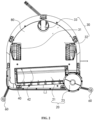
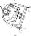
- a cleaning robot includes a robot body 10, a cleaning system 20, a driving system 30, a recovery system 40, a blocking assembly 50, a detection system 60, a perception system 70, a control system 80, an energy system 90, and a human-machine interaction system 100.
- the robot body 10 includes a forward portion 12 and a backward portion 13, and the robot body 10 is approximately in a circular shape (both the forward portion and the backward portion are circular), or other shapes, including but not limited to an approximate D-shape with a square forward portion and a circular backward portion, and a rectangular or square shape with a square forward portion and a square backward portion.
- the perception system 70 includes a position determination device 71 disposed on the robot body 10, and sensing devices such as a collision sensor disposed on a buffer 72 on the forward portion 12 of the robot body 10, a proximity sensor disposed on the robot body 10, a cliff sensor disposed at a lower part of the robot body, and a magnetometer, an accelerometer, a gyroscope, and an odometer disposed in the robot body 10, which are configured to provide various position information and motion state information of the cleaning robot to the control system 80.
- the position determination device 71 includes but is not limited to a camera and a laser distance sensor (LDS).
- the forward portion 12 of the robot body 10 may carry the buffer 72.
- the buffer 72 detects one or more events in a travelling path of the cleaning robot via the collision sensor disposed thereon.
- the cleaning robot may respond to events detected by the buffer 72, such as an obstacles or a wall, by controlling the driving system 30, such that the cleaning robot performs a response to the event, such as moving away from the obstacle.
- the control system 80 is disposed on a main circuit board in the robot body 10, and includes a computing processor, such as a central processing unit or an application processor, which communicates with non-temporary memories, such as a hard disk, a flash memory, and a random access memory.
- the application processor draws, by using a positioning algorithm (for example, simultaneous localization and mapping (SLAM)) according to obstacle information fed back by the laser distance sensor, a simultaneous map of an environment where the cleaning robot is disposed.
- a positioning algorithm for example, simultaneous localization and mapping (SLAM)
- the control system 80 comprehensively determines, according to distance information and speed information fed back by the sensing devices such as the sensor disposed on the buffer 72, the cliff sensor, the magnetometer, the accelerometer, the gyroscope, and the odometer, a current working state, a current position, and a current posture of the cleaning robot, such as crossing a threshold, crawling onto a carpet, being at a cliff, being stuck from above or below, having a full dust box or being picked up, etc., and may also provide specific next action strategies for different situations, such that the cleaning robot has better sweeping performance and provides better user experience.
- the sensing devices such as the sensor disposed on the buffer 72, the cliff sensor, the magnetometer, the accelerometer, the gyroscope, and the odometer, a current working state, a current position, and a current posture of the cleaning robot, such as crossing a threshold, crawling onto a carpet, being at a cliff, being stuck from above or below, having a full dust box or
- the driving system 30 may control the robot body 10 to travel across the floor based on a driving command with distance and angle information (such as x, y and ⁇ components).
- the driving system 30 may include a first driving wheel module 31 and a second driving wheel module 32.
- the first driving wheel module 31 and the second driving wheel module 32 are disposed along a transverse axis defined by the robot body 10.
- the cleaning robot may include one or more driven wheels 33, and the driven wheels include but are not limited to a universal wheel.
- the driving wheel module includes a walking wheel, a driving motor, and a control circuit for controlling the driving motor.
- the driving wheel module may also be connected to a circuit for measuring a driving current and an odometer.
- the driving wheel module may be detachably connected onto the robot body 10 in order to be dismounted, mounted and maintained conveniently.
- the driving wheel may be provided with an offset drop suspension system, which is movably fastened, for example, rotatably attached, to the robot body 10 to receive spring biases that are biased downwards and away from the robot body 10.
- the spring biases allow the driving wheel to maintain contact and traction with the floor with certain floor attachment force, and a cleaning element of the cleaning robot is also in contact with the floor with a certain pressure.
- the robot body 10 defines the transverse axis and a longitudinal axis.
- the transverse axis and the longitudinal axis are perpendicular to each other, and the transverse axis and the longitudinal axis may be understood as a transverse centerline and a longitudinal centerline of the robot body 10, respectively.
- the energy system 90 includes a rechargeable battery, such as a nickel-hydrogen battery and a lithium battery.
- the rechargeable battery may be connected to a charging control circuit, a battery pack charging temperature detecting circuit, and a battery undervoltage monitoring circuit which are connected to a single-chip microcomputer control circuit.
- the cleaning robot may be connected to a charging pile for charging via a charging electrode disposed on the robot body, such as disposed on the side, the bottom or the top of the robot body.
- the human-machine interaction system 100 may include buttons on a host panel for a user to select functions, and may further include a display screen and/or an indicator light and/or a speaker which show the current state or function options of the cleaning robot to the user, and also include a mobile phone client program.
- the mobile phone client may show the user a map of the environment where the cleaning robot is disposed, and also the location of the cleaning robot, thereby providing the user with richer and more user-friendly function items.
- the cleaning system 20 is disposed on the robot body 10, and includes a cleaning head 21.
- the transverse axis of the robot body 10 is set at a preset included angle with the cleaning head 21, to reduce the probability of the cleaning head 21 being stuck by floor joints when the cleaning robot passes through floor environments such as tile joints in an advancing process, thereby improving the cleaning efficiency and the use performance of the cleaning robot.
- the preset included angle between the transverse axis and the cleaning head 21 may be an acute angle, and may range from 5 degrees to 70 degrees.
- the cleaning system 20 may be a dry cleaning system.
- the dry cleaning system may include the cleaning head 21, a dust box, a fan, an air outlet, etc.
- the cleaning head 21 may be a roller brush rotatable around a shaft that is parallel to the floor. The roller brush with certain interference with the floor sweeps up garbage on the floor, and rolls up it to the front of a dust suction inlet between the roller brush and the dust box, and then the garbage is sucked into the dust box by air with a suction force, where the air is generated by the fan and passes through the dust box.
- the dust removal capacity of the cleaning robot may be characterized by the dust pickup (DPU) efficiency of the garbage.
- the DUP is affected by a structure and a material of the roller brush, an air utilization rate of an air duct, and a type and a power of the fan, which is a complex problem of system design
- the air duct is formed by the dust suction inlet, the dust box, the fan, the air outlet, and connecting parts among them.
- the cleaning system 20 may be a wet cleaning system.
- the cleaning head 21 includes a wet cleaning head.
- the cleaning system 20 further includes a liquid supply part 22, and the liquid supply part 22 feeds a washing liquid into the wet cleaning head.
- the cleaning head 21 may be disposed below the liquid supply part 22, and the cleaning liquid inside the liquid supply part 22 is delivered to the cleaning head 21 through a water delivery mechanism, such that the cleaning head 21 performs the wet cleaning on a surface to be cleaned.
- the cleaning liquid inside the liquid supply part 22 may also be directly sprayed onto the surface to be cleaned, and the cleaning head 21 cleans the surface by evenly applying the cleaning liquid.
- the cleaning head 21 may be disposed at the bottom of the robot body 10.
- the cleaning head 21 may be a cleaning pad disposed parallel to the surface to be cleaned.
- the cleaning head 21 is configured to clean the surface to be cleaned.
- the driving system 30 is configured to drive the cleaning head 21 to basically reciprocate along a target surface.
- the target surface is a part of the surface to be cleaned.
- the cleaning head 21 reciprocates along the surface to be cleaned.
- a cleaning cloth or a cleaning plate is provided on a surface of the cleaning head 21 in contact with the surface to be cleaned, and generates high-frequency friction with the surface to be cleaned through reciprocating motion to remove stains on the surface to be cleaned.
- the high-frequency reciprocating motion also known as reciprocating vibration, has a cleaning capability much higher than that of ordinary reciprocating motion, such as rotational friction cleaning.
- the friction frequency is approximate to the frequency of sound waves, and the cleaning effect may be much higher than that of rotational friction cleaning with dozens of revolutions per minute.
- bristle tufts on the surface of the cleaning head 21 may spread more neatly in the same direction under shaking of high-frequency vibration, such that the overall cleaning effect is more uniform, rather than that under the condition of low-frequency rotation, only a downward pressure is applied to increase the friction force to improve the cleaning effect.
- the downward pressure alone may not make the bristle tufts spread in approximately the same direction.
- the cleaning head 21 may also be of a strip-shaped structure, etc.
- the cleaning head 21 may be a roller brush rotatable around an axis parallel to the surface to be cleaned, as shown in FIG. 16 .
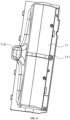
- the robot body 10 includes a fixed bracket 11 in which the cleaning head 21 is disposed, the fixed bracket 11 is provided with a liquid supply channel through which the liquid supply part 22 feeds the washing liquid into the wet cleaning head.
- the liquid supply channel may be constituted by a chamber formed inside the fixed bracket 11, for example, a part of the fixed bracket 11 is hollow so as to form the liquid supply channel for circulating the washing liquid.
- the liquid supply channel may be formed by a pipe body so as to feed the washing liquid from the liquid supply part 22 to the wet cleaning head, thereby ensuring that the cleaning head 21 effectively cleans the surface to be cleaned.
- the liquid supply channel includes a liquid inlet 111 and a liquid outlet 112.
- the liquid inlet 111 is communicated with the liquid supply part 22, and the liquid outlet 112 is configured to feed the washing liquid into the cleaning head 21.
- the fixed bracket 11 is provided with the liquid inlet 111 and the liquid outlet 112, an end of the liquid inlet 111 is disposed on an outer surface of the fixed bracket 11, the liquid outlet 112 is disposed on an inner surface of the fixed bracket 11, a main body portion of the liquid supply channel may be disposed between the liquid inlet 111 and the liquid outlet 112, and the main body portion may be communicated with a plurality of liquid outlets 112, such that the liquid outlets 112 feed the washing liquid into the cleaning head 21.
- an accommodating chamber 113 is formed in the fixed bracket 11, the liquid outlet 112 is disposed on a chamber wall of the accommodating chamber 113, and the liquid outlet 112 may be arranged on a top portion or a side portion of the accommodating chamber 113.
- the liquid supply channel may have one liquid inlet 111, and the one liquid inlet 111 corresponds to all of the liquid outlets 112.
- the liquid supply channel may have at least two liquid inlets 111, and each of the liquid inlets 111 may respectively correspond to the plurality of liquid outlets 112, so as to reliably feed the washing liquid to the wet cleaning head.
- the liquid inlet 111 may be formed by a columnar structure to be connected to a pipe-shaped structure which feeds the washing liquid.
- the liquid outlet 112 may be a rectangular port, a circular port or other polygonal structure, which is not limited herein.
- the plurality of liquid outlets 112 are disposed sequentially in the direction parallel to the cleaning head 21.
- the recovery system 40 is disposed on the robot body 10, and includes a collecting part 41.
- the collecting part 41 collects residues on the cleaning head 21 and/or residues on the surface to be cleaned, thereby effectively clean the surface to be cleaned and ensuring the cleanliness of the surface to be cleaned.
- the cleaning robot cleans the surface to be cleaned by rotating the cleaning head 21.
- the residues on the surface to be cleaned may be adsorbed onto the cleaning head 21, and the collecting part 41 may collect these residues to ensure the cleanliness of the cleaning head 21.
- the collecting part 41 may also collect the residues on the surface to be cleaned, and thus cooperates with the cleaning head 21 to achieve reliable cleaning of the surface to be cleaned.
- the residues may be water, debris, etc., which is not limited herein.
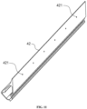
- the recovery system 42 further includes a squeegee strip 42.
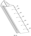
- the squeegee strip 42 is in contact with the cleaning head 21, and removes the residues from the cleaning head 21 by interfering with the cleaning head 21, such that the residues are collected by the collecting part 41.
- the cleanliness of the cleaning head 21 is ensured, thereby ensuring that the surface to be cleaned is effectively cleaned.
- the squeegee strip 42 may be of a plate-like structure, and the plate-like structure interferes with the cleaning head 21.
- the plate-like structure may remove the residues from the cleaning head 21 during rotation of the cleaning head 21, such that the residues are collected by the collecting part 41, thereby ensuring that the residues adsorbed from the surface to be cleaned may be collected by the collecting part 41 in a timely manner.
- the squeegee strip 42 may be disposed on the robot body 10.
- the squeegee strip 42 is detachably disposed on the robot body 10.
- the squeegee strip 42 is parallel to the cleaning head 21, such that the squeegee strip 42 may remove the residues from the cleaning head 21 reliably and the structure may be mounted conveniently.
- a length of the squeegee strip 42 may be equal to a length of the cleaning head 21.
- the squeegee strip 42 may be avoided from occupying the space in the length direction, thereby ensuring the compactness of the structure.
- the transverse axis of the robot body 10 is parallel to both the cleaning head 21 and the squeegee strip 42.
- the squeegee strip 42 is provided with a water suction port 421, and the water suction port 421 is communicated with the collecting part 41, such that the recovery system 40 reliably collects the sewage into the collecting part 41 through the water suction port 421.
- the water suction port 421 may face towards the cleaning head 21. After the sewage on the cleaning head 21 is scraped off by the squeegee strip 42, the sewage may flow along the squeegee strip 42 and flow towards the water suction port 421, such that the sewage may be pumped into the collecting part 41 via the water suction port 421 by the recovery system 40.
- the water suction port 421 may be disposed on a side of the squeegee strip 42 away from the cleaning head 21, a part of the squeegee strip 42 may gather the sewage together, and the water suction port 421 pumps the gathered sewage into the collecting part 41.
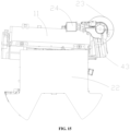
- the recovery system 40 further includes a power part 43 in pneumatic communication with the collecting part 41 to collect the residues to the collecting part 41.
- a negative pressure may be generated between the power part 43 and the collecting part 41, such that the residues on the surface to be cleaned and the residues on the cleaning head 21 may be sucked into the collecting part 41.
- the negative pressure generated between the power part 43 and the collecting part 41 may suck the sewage into the collecting part 41 through the water suction port 421.
- the power part 43 may be a fan.
- the accommodating chamber 113 is formed in the fixed bracket 11.
- the cleaning head 21 is disposed in the accommodating chamber 113, and the collecting part 41 is communicated with the accommodating chamber 113, such that the residues enter the collecting part 41 after passing through the accommodating chamber 113.
- the fixed bracket 11 is defined with a through hole 114, and the through hole 114 is communicated with the collecting part 41 and the accommodating chamber 113.
- the residues scraped off from the cleaning head 21 by the squeegee strip 42 are disposed in the accommodating chamber 113 of the fixed bracket 11, such that the negative pressure generated between the power part 43 and the collecting part 41 may suck the residues in the accommodating chamber 113 into the collecting part 41 via the through hole 114.
- the accommodating chamber 113 of the fixed bracket 11 may form a relatively sealed space with the surface to be cleaned. Thus, the negative pressure generated between the power part 43 and the collecting part 41 may suck the residues on the surface to be cleaned into the collecting part 41 via the through hole 114.
- the collecting part 41 includes an inlet 411 and an outlet 412.
- the inlet 411 may be communicated with the accommodating chamber 113. Further, the inlet 411 may be communicated with the through hole 114, and the outlet 412 may be communicated with the power part 43, such that the power part 43 provides power through the outlet 412 of the collecting part 41 to suck the residues into the inlet 411 of the collecting part 41 from the through hole 114 of the accommodating chamber 113, and thus, the residues enter the collecting part 41.
- the sewage, debris, etc. carried in the airflow remain in the collecting part 41 under the action of gravity. Therefore, when the airflow has a relatively long flow path in the collecting part 41, the sewage, debris, etc. may be effectively separated from the airflow.
- the inlet 411 and the outlet 412 of the collecting part 41 may be disposed on the same side of the collecting part 41.
- the inlet 411 and the outlet 412 of the collecting part 41 are both disposed on a front side of the collecting part 41.
- Such an arrangement may effectively extend the flow path of the airflow in the collecting part 41, such that sewage, debris, etc. may be separated from the airflow more effectively.
- the blocking assembly 50 of the cleaning robot is disposed on the robot body 10. At least a part of the blocking assembly 50 is adjustably arranged so as to close or release the inlet 411 and the outlet 412 of the collecting part 41, thereby avoiding the debris in the collecting part 41 from being poured out from the inlet 411 or avoiding the debris in the collecting part 41 from entering the power part 43 from the outlet 412.
- the blocking assembly 50 may close the inlet 411 and the outlet 412 of the collecting part 41 when the cleaning robot is not in operation, and thus, the problem that the residues are poured out incidentally due to manual movement of the cleaning robot may be avoided.
- the blocking assembly 50 may release the inlet 411 and the outlet 412 of the collecting part 41, such that the residues may be pumped into the collecting part 41 from the inlet 411.
- the blocking assembly 50 may be controlled by an independent motor, and may achieve the closing control of the inlet 411 and the outlet 412 of the collecting part 41 at any time, and for example, the blocking assembly 50 may be closed when the cleaning robot is not in operation.
- the motor of the blocking assembly 50 may be electrically connected to the control system 80 of the cleaning robot, such that the blocking assembly 50 is controlled according to the motion state of the cleaning robot fed back by the control system 80.
- the control system 80 controls the cleaning robot to stop operating, it may control the blocking assembly 50 to close the inlet 411 and the outlet 412 of the collecting part 41.
- control system 80 when the control system 80 detects that the cleaning robot is in an inclined state, it may control the blocking assembly 50 to close the inlet 411 and the outlet 412 of the collecting part 41.
- the control system 80 when the control system 80 detects that the cleaning robot is in an idle state for a long period of time, for example, the cleaning robot is stuck in a fixed position during cleaning and thus cannot advance, it may control the blocking assembly 50 to close the inlet 411 and the outlet 412 of the collecting part 41.
- the control system 80 when the control system 80 detects that the garbage in the collecting part 41 reaches a certain height, the control system 80may control the blocking assembly 50 to close the inlet 411 and the outlet 412 of the collecting part 41.
- the user may use an application software (app) to control the blocking assembly 50, and the like, so as to meet use requirements, in addition, the closing of the inlet 411 and the outlet 412 of the collecting part 41 may be flexibly controlled.
- app application software
- the blocking assembly 50 includes a connecting rod 51, a first blocking member 52 disposed on the connecting rod 51, and a second blocking member 53 disposed on the connecting rod 51.
- the connecting rod 51 is movably disposed relative to the robot body 10, such that the first blocking member 52 and the second blocking member 53 close or release the inlet 411 and the outlet 412, respectively. That is, the first blocking member 52 and the second blocking member 53 may close or release the inlet 411 and the outlet 412 synchronously, in order to improve the operating performance of the cleaning robot and ensure that the residues are sucked into the collecting part 41 in a timely manner.
- the blocking assembly 50 may include a driving part 54.
- the driving part 54 may be a motor.
- the driving part 54 is in driving connection to the connecting rod 51, so as to drive the connecting rod 51 to rotate, and thus drive the first blocking member 52 and the second blocking member 53 to rotate, thereby closing or releasing the inlet 411 and the outlet 412.
- the first blocking member 52 and the second blocking member 53 are spaced apart from each other on the connecting rod 51, the first blocking member 52 and the second blocking member 53 are located on the middle of the connecting rod 51.
- One end of the connecting rod 51 is connected to the driving part 54, the other end of the connecting rod 51 extends beyond the second blocking member 53, and the first blocking member 52 is disposed between the driving part 54 and the second blocking member 53.
- the first blocking member 52 and the second blocking member 53 are disposed at positions of the connecting rod 51 close to two opposite ends of the connecting rod 51, respectively.
- the first blocking member 52 and the second blocking member 53 are detachably disposed on the connecting rod 51, or both integrally formed on the connecting rod 51.
- the driving part 54 may be a cylinder, an oil cylinder or a telescopic motor.
- the driving part 54 is connected to the connecting rod 51, and performs telescopic motion through a telescopic link of the driving part 54, and that is, the connecting rod 51 may perform telescopic motion.
- the connecting rod 51 may move forward and backward, such that the first blocking member 52 and the second blocking member 53 may move forward and backward, i.e., moving along a direction parallel to a plane where the inlet 411 and the outlet 412 of the collecting part 41 are disposed, so as to close or release the inlet and 411 and the outlet 412 of the collecting part 41.
- the driving part 54 may be a cylinder, an oil cylinder or a telescopic motor.
- the driving part 54 is connected to the connecting rod 51 and performs telescopic motion through a telescopic link of the driving part 54, and that is, the connecting rod 51 may perform telescopic motion.
- the connecting rod 51 may move up and down.
- the first blocking member 52 and the second blocking member 53 may move up and down, i.e., moving along a direction perpendicular to a plane where the inlet 411 and the outlet 412 of the collecting part 41 are disposed, so as to close or release the inlet and 411 and the outlet 412 of the collecting part 41.
- the first blocking member 52 and the second blocking member 53 of the blocking assembly 50 may be independently disposed on a first driving part and a second driving part.
- the first driving part and the second driving part drive the first blocking member 52 and the second blocking member 53 respectively to move, so as to close or release the inlet 411 and the outlet 412.
- the first driving part and the second driving part may operate synchronously, such that the first blocking member 52 and the second blocking member 53 operate synchronously, so as to synchronously close or release the inlet 411 and the outlet 412.
- Each of the first driving part and the second driving part may be a motor, a cylinder, an oil cylinder or other power mechanism.
- the blocking assembly 50 may include a connecting rod 51, a first blocking member 52, a second blocking member 53, a driving part 54, and an ejector pin 55.
- the first blocking member 52 and the second blocking member 53 are connected onto the connecting rod 51.
- the ejector pin 55 may be connected to the first blocking member 52.
- the driving part 54 is in driving connection to the ejector pin 55, such that the driving part 54 may drive the ejector pin 55 to move up and down. In this way, the first blocking member 52 and the second blocking member 53 move up and down, or the connecting rod 51 drives the first blocking member 52 and the second blocking member 53 to rotate, so as to synchronously close or release the inlet 411 and the outlet 412.
- the blocking assembly 50 may further include an elastic member 56.
- the elastic member 56 may drive the ejector pin 55 to return to its original position, such that the first blocking member 52 and the second blocking member 53 are moved from a position where the inlet 411 and the outlet 412 are released to a position where the inlet 411 and the outlet 412 are closed.
- the elastic member 56 may be a spring.
- the spring may be fitted over the connecting rod 51. One end of the spring abuts against the first blocking member 52, and the other end of the spring may be supported on other components of the cleaning robot.
- the other end of the spring may abut against the robot body 10, such that the spring may be pressed tightly when the ejector pin 55 moves upward, and after the ejector pin 55 loses power, the spring returns to its original position.
- the first blocking member 52 and the second blocking member 53 are driven to move from a position where the inlet 411 and the outlet 412 are released to a position where the inlet 411 and the outlet 412 are closed.
- the other end of the connecting rod 51 may be passively rotated.
- the spring may abut against the first blocking member 52 or the second blocking member 53.
- At least two springs may be provided. The two springs are disposed at two ends of the connecting rod 51, respectively, and may abut against the first blocking member 52 and the second blocking member 53, respectively.
- the connecting rod 51 may rotate in a first direction, such that the first blocking member 52 and the second blocking member 53 release the inlet 411 and the outlet 412.
- the elastic member 56 is pressed tightly, after the driving part 54 releases the power or after the driving part 54 operates reversely, for example, the ejector pin 55 moves upward when the motor rotates forward, while when the motor rotates reversely, the driving part 54 may not be fixedly connected to the ejector pin 55, the connecting rod 51 is driven to rotate in a second direction by a driving force, the driving force is generated by restoring the elastic member 56 to its original state, such that the ejector pin 55 is pressed to move downward.
- the driving part 54 may include a cam mechanism, through which the ejector pin 55 is driven to move upward.
- the ejector pin 55 may be in contact with the cam mechanism, but not fixed.
- the driving part 54 may include an electric push rod, the electric push rod may only be in insertable connection to the ejector pin 55, and the electric push rod and the ejector pin are not fixed axially.
- it is not excluded that the driving part 54 may be fixedly connected to the connecting rod 51, and thus, the elastic member 56 may be cancelled.
- the driving part 54 drives the ejector pin 55 to move upward.
- the driving part 54 may include a cam mechanism, a gear mechanism, etc. as long as the driving part 54 may achieve rectilinear motion to push the ejector pin 55 to perform rectilinear motion.
- the blocking assembly 50 may further include a sealing member 57, the sealing member 57 may be disposed on the collecting part 41, and that is, the collecting part 41 may be defined with a through hole.
- the ejector pin 55 may pass through the through hole to be connected to the driving part 54, and the sealing member 57 is configured to block a gap between a hole wall of the through hole and the ejector pin 55, so as to avoid the sewage flowing out of the collecting part 41.
- the ejector pin 55 may move up and down inside the sealing member 57.
- the sealing member 57 may be a sealing ring.
- the collecting part 41 may include at least two sub-chambers, a first sub-chamber is configured to store sewage and a second sub-chamber is an empty chamber in a normal state. Only after a water level in the first sub-chamber reaches a certain value, the sewage flows into the second sub-chamber. The ejector pin 55 passes through the second sub-chamber, and thus, in the normal state, there is no liquid leakage in the second sub-chamber. However, the arrangement of the sealing member 57 may effectively prevent liquid leakage in a case that there is liquid in the second sub-chamber.
- the ejector pin 55 may prop open the first blocking member 52 and the second blocking member 53.
- the first blocking member 52 and the second blocking member 53 lose the support from the ejector pin 55, and are closed under the action of the spring force.
- a program controls the ejector pin 55 to move, such that the ejector pin 55 cannot support the first blocking member 52 and the second blocking member 53, and under the action of the spring force, the first blocking member 52 and the second blocking member 53 are closed.
- the cleaning system 20 may be disposed on the forward portion 12 of the robot body 10, and at least a part of the driving system 30 may be disposed on the backward portion 13 of the robot body 10.
- the driven wheel 33 of the driving system 30 may be disposed at an edge of the backward portion 13.
- the forward portion 12 may be substantially rectangular in shape, and the backward portion 13 may be substantially of a semi-circle shape.
- substantially rectangular means that in addition to a rectangle, it may also be a shape that looks like a rectangle but is actually different from a perfect rectangle.
- this shape may have rounded corners or include a special-shaped shape around the edges resulting from some structural avoidance, or the included angle of the shape has an angle deviations of up to ⁇ 5 degrees from a right angle, and the like.
- the cleaning system 20 further includes an auxiliary cleaning head 23, and the auxiliary cleaning head 23 is disposed on the robot body 10.
- the cleaning robot may better clean wall edges, wall corners and other regions, thereby improving the cleaning effect of the cleaning system 20.
- the auxiliary cleaning head 23 is disposed at a corner position of the robot body 10, and a part of the auxiliary cleaning head 23 extends beyond the robot body 10.
- the part of the auxiliary cleaning head 23 extending beyond the robot body 10 is less than a part of the auxiliary cleaning head 23 disposed below the robot body 10, so as to prevent the auxiliary cleaning head 23 from excessively increasing the occupied area of the cleaning robot on the basis of ensuring a cleaning range of the auxiliary cleaning head 23.
- the robot body 10 includes the forward portion 12 and the backward portion 13.
- the forward portion 12 is substantially rectangular body. That is, in the case of ignoring fabrication errors, installation errors, etc., a circumferential outer surface of the rectangular body may include corner regions with rounded transitions.
- the rectangular body here only emphasizes a general structure of the forward portion 12.
- the auxiliary cleaning head 23 is disposed at a corner position of the forward portion 12.
- the auxiliary cleaning head 23 is disposed at a position of the robot body 10 close to the forward portion 12, and a part of the auxiliary cleaning head 23 extends beyond the carried buffer 72. In a case that the cleaning robot is blocked by an obstacle in front, the auxiliary cleaning head 23 may also clean the gap and other parts in front, thereby improving the cleaning capability of the cleaning robot.
- a preset included angle is formed between the transverse axis of the robot body 10 and the cleaning head 21. That is, the cleaning head 21 is disposed in an inclined manner.
- the auxiliary cleaning head 23 is disposed on a side of the cleaning head 21 which is inclined backward, such that the area of the auxiliary cleaning head 23 may be increased. That is, without excessively increasing the part of the auxiliary cleaning head 23 that extends beyond the robot body 10, the auxiliary cleaning head 23 may have a relatively great area, thereby ensuring that the cleaning system 20 has an enough cleaning area.
- the outer edge of the auxiliary cleaning head 23 is substantially circular.
- the part of the auxiliary cleaning head 23 overlaps with the cleaning head 21. In this way, on the basis of ensuring that a combination of the auxiliary cleaning head 23 and the cleaning head 21 may increase the cleaning area, the problem of missing cleaning between the auxiliary cleaning head 23 and the cleaning head 21 may be avoided, thereby improving the cleaning effect of the cleaning system 20.
- the outer edge of the auxiliary cleaning head 23 extends beyond the outer edge of the robot body 10. That is, the auxiliary cleaning head 23 may clean positions at outer edges of the robot body 10, such as wall edges, wall corners, and other regions, thereby increasing the cleaning area of the cleaning system 20 and improving the cleaning performance of the cleaning robot.
- the auxiliary cleaning head 23 includes a wet auxiliary cleaning head 231.
- the liquid supply part 22 feeds the washing liquid into the wet auxiliary cleaning head 231.
- the auxiliary cleaning head 23 may be disposed below the liquid supply part 22.
- the cleaning liquid inside the liquid supply part 22 is delivered to the auxiliary cleaning head 23 through a water delivery mechanism, such that the auxiliary cleaning head 23 performs wet cleaning on the surface to be cleaned.
- the cleaning system 20 may further include an auxiliary liquid supply channel, through which the liquid supply channel 22 feeds the washing liquid into the wet auxiliary cleaning head 231.
- the auxiliary liquid supply channel may be a space formed inside the auxiliary cleaning head 23.
- the washing liquid is fed into the wet auxiliary cleaning head 231 through the liquid outlet.
- the auxiliary liquid supply channel may be a liquid feed pipe to feed the washing liquid to the wet auxiliary cleaning head 231.
- the cleaning system 20 further includes a water pump 24.
- the water pump 24 is communicated with the liquid supply part 22, so as to feed the washing liquid from the liquid supply part 22 onto at least one of the cleaning head 21 and the auxiliary cleaning head 23.
- the water pump 24 may feed the washing liquid from the liquid supply part 22 to the cleaning head 21 through the liquid supply channel, and/or feed the washing liquid from the liquid supply part 22 to the auxiliary cleaning head 23 through the auxiliary liquid supply channel.
- the one water pump 24 may be communicated with both the liquid supply channel and the auxiliary liquid supply channel.
- the water pump 24 may be a gear pump, a vane pump, a piston pump, a peristaltic pump or the like.
- the power/flow of the water pump 24 is adjustable.
- the water pump 24 may cooperate with a valve and other devices to control the supply of the washing liquid from the liquid supply part 22 to the cleaning head 21 and the auxiliary cleaning head 23.
- the cleaning head 21 is rotatably disposed around a first axis
- the auxiliary cleaning head 23 is rotatably disposed around a second axis.
- a certain included angle is formed between the first axis and the second axis.
- the cleaning head 21 may be a roller brush for mopping.
- the auxiliary cleaning head 23 may include cloth or wool.
- the washing liquid in the liquid supply part 22 is evenly distributed on the auxiliary cleaning head 23 through the penetration and centrifugal force of the cloth or wool.
- the auxiliary cleaning head 23 may float in an up-down direction to a certain extent.
- the first axis is perpendicular to the second axis. That is, the first axis may be parallel to the surface to be cleaned, and the second axis may be perpendicular to the surface to be cleaned.
- the auxiliary cleaning head 23 may be a side brush.
- the rotation axis of the side brush is at a certain angle relative to the floor, so as to move the residues on the surface to be cleaned into the cleaning region of the cleaning head 21.
- the auxiliary cleaning head 23 may be in the form of a disc brush, a roller brush or the like.
- the auxiliary cleaning head 23 may further include a main body part 232, the wet auxiliary cleaning head 231 is connected onto the main body part 232, and the main body part 232 is disposed on the robot body 10.
- the main body part 232 may include a driving motor.
- the driving motor may drive the wet auxiliary cleaning head 231 to rotate.
- the wet auxiliary cleaning head 231 may include cloth or wool.
- the main body part 232 may include a support structure.
- the support structure may be a tapered soft rubber support, so as to transfer a relatively large torque, and allow the wet auxiliary cleaning head 231 to float in an up-down direction to a certain extent, thereby improving the cleaning capability.
- the liquid supply part 22 and the collecting part 41 are stacked, such that the space utilization ratio of the cleaning robot may be increased, and the cleaning robot may be prevented from being too large.
- the liquid supply part 22 is disposed above the collecting part 41.
- the liquid supply part 22 may be a clean water tank.
- the collecting part 41 may be a sewage tank.
- the arrangement that the clean water tank is disposed above may facilitate the liquid supply to the cleaning head 21 and the auxiliary cleaning head 23.
- the arrangement that the sewage tank is disposed below may facilitate the recovery of the residues.
- the clean water tank and the sewage tank may be vertically stacked. That is, as shown in FIG. 15 and FIG. 16 , the liquid supply part 22 and the collecting part 41 are vertically stacked.
- the clean water tank may be disposed above the sewage tank. The arrangement that the clean water tank is disposed above may facilitate the liquid supply to the cleaning head 21 and the auxiliary cleaning head 23. The arrangement that the sewage tank is disposed below may facilitate the recovery of the residues.
- the clean water tank and the sewage tank are vertically stacked, such that the center of gravity of the cleaning robot does not change much in the horizontal direction, thereby ensuring the stability of the cleaning robot and avoiding significant shaking during cleaning.
- the collecting part 41 may be disposed in the middle position of the robot body 10. That is, the collecting part 41 may be disposed on a side of the cleaning system 20 away from the born buffer 72. In this way, the center of gravity of the cleaning robot will not change much when the amount of water in the collecting part 41 changes. Thus, it is ensured that the cleaning robot may stably clean the surface to be cleaned, and the center of gravity is stable during use.
- the liquid supply part 22 and the collecting part 41 are vertically stacked.
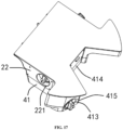
- the liquid supply part 22 is provided with a water inlet 221.
- the collecting part 41 is provided with a drainage port 413.
- the water inlet 221 in the liquid supply part 22 is configured to inject clean water into the liquid supply part 22.
- the drainage port 413 in the collecting part 41 is configured to discharge sewage in the collecting part 41 from the collecting part 41.
- the water inlet 221 may be disposed on a side of the liquid supply part 22.
- the drainage port 413 may be disposed on a side of the collecting part 41.
- two ports may be disposed on the bottom or the side of the robot body 10, and the two ports may be configured to be connected to a clean water injection structure and a sewage discharge structure.
- the two ports need to be in a blocked state, so as to avoid water leakage.
- the water inlet 221 and the drainage port 413 may be sealed with a sealing member.
- the liquid supply part 22 and the collecting part 41 may be simultaneously removed from the robot body 10.
- the liquid supply part 22 is connected to the collecting part 41, such that the liquid supply part 22 and the collecting part 41 may be removed from the robot body 10 synchronously.
- the liquid supply part 22 and the collecting part 41 may be removed from the robot body 10, so as to achieve the liquid injection of the liquid supply part 22 and the sewage discharge of the collecting part 41.
- the collecting part 41 may be a special-shaped structure, and may include a main body 414 and an extension part 415 connected to the main body 414.
- the main body 414 and the extension part 415 together form a chamber for collecting the sewage.
- the main body 414 may be substantially a rectangular body.
- the extension part 415 is an irregular special-shaped structure.
- the extension part 415 may be substantially divided into a triangle and a rectangle, or a semicircle and a rectangle, etc., which is not limited here.
- the space of the extension part 415 for accommodating the sewage is less than the space of the main body 414 for accommodating the sewage.
- the drainage port 413 is arranged on the extension part 415, and thus, when the sewage is discharged, the sewage may be gathered in the extension part 415 by tilting the collecting part 41, so as to ensure that the sewage is discharged smoothly, thereby avoiding the sewage which cannot be discharged from accumulating in the collecting part 41.
- a plurality of cliff sensors may be disposed around circumferential edge positions of the robot body 10.
- the auxiliary cleaning head 23 is disposed at the corner position of the robot body 10.
- the cliff sensor may be disposed at a position of the robot body 10 close to the auxiliary cleaning head 23.
- At least two cliff sensors may be disposed at the position of the robot body 10 close to the auxiliary cleaning head 23.
- the cliff sensors may identify the surface to be cleaned to determine physical characteristics of the surface to be cleaned, including the surface material, the degree of cleanliness, etc.
- the control system 80 may control an operating state of the auxiliary cleaning head 23 according to an identification result of the cliff sensor, so as to ensure the cleaning function of the auxiliary cleaning head 23.
- the auxiliary cleaning head 23 may be controlled to increase humidity, so as to ensure the cleaning effect.
- the auxiliary cleaning head 23 may be controlled to reduce humidity, so as to avoid from wetting the carpet.
- the detection system 60 of the cleaning robot is disposed on the robot body 10. At least a part of the detection system 60 extends from the outer edge of the robot body 10, so as to increase the detection range of the detection system 60 and thereby increase the flexible adjustment capability of the cleaning robot.
- the detection system 60 may be an ultrasonic sensor, an infrared sensor or other sensors, and the detection system 60 is configured to detect changes in the material of the surface to be cleaned, changes in the level of the surface to be cleaned or perform dirt detection and the like.
- the detection system 60 is movably disposed relative to the robot body 10, such that the position of the detection system 60 may be reliably adjusted to adapt to different application environments.
- the detection system 60 may achieve position adjustment under the driving of the driving mechanism.
- the detection system 60 may include a flexible mechanism, and the position adjustment is performed by deforming the flexible mechanism.
- the detection system 60 is retractably disposed on the robot body 10, and has an extended state and a retracted state.
- the detection system When the detection system is extended to the front of the cleaning robot, it may detect the floor condition in front of the cleaning robot.
- the detection system 60 may be disposed near the corner of the cleaning robot, such that it is convenient for the detection system 60 to detect the floor condition in front or at the side in the retracted state.
- the detection system 60 When the cleaning robot is a circular cleaning robot, the detection system 60 may be disposed at the front of the cleaning robot.
- the detection system 60 may extend from the outer edge of the robot body 10, such that the detection system 60 has a retracted state in which the detection system 60 is retracted in the robot body 10 and an extended state in which the detection system 60 extends from the robot body 10.
- the control system 80 may control the motion of the detection system 60 between the retracted state and the extended state. In this way, the detection system 60 may be adjusted in real time according to the operating state or the operating path of the cleaning robot, thereby ensuring that the detection system 60 may accurately determine the state of the surface to be cleaned.
- the driving system 30 may drive the cleaning robot to operate on a working surface
- the control system 80 may drive the detection system 60 to move from the retracted state to the extended state, such that the detection system 60 may monitor the state of the working surface in real time.
- the detection system 60 has a detection view angle towards the working surface, and thus may precisely detect the state of the working surface, for example, changes in the material of the working surface, changes in the level of the working surface, or dirt detection and the like.
- the detection system 60 may be connected to the corner position of the robot body 10.
- the auxiliary cleaning head 23 may be disposed at a position of the robot body 10 close to the detection system 60.
- the detection system 60 may identify the surface to be cleaned in advance, so as to determine the physical characteristics of the surface to be cleaned, including the surface material, the degree of cleanliness, etc.
- the control system 80 may control the operating state of the auxiliary cleaning head 23 according to the identification result of the detection system 60, so as to ensure the cleaning function of the auxiliary cleaning head 23.
- the auxiliary cleaning head 23 may be controlled to increase humidity, so as to ensure the cleaning effect.
- the auxiliary cleaning head 23 may be controlled to reduce humidity, so as to avoid wetting the carpet.
- the detection system 60 is retractably disposed on the forward portion 12 of the robot body 10, such that the detection system 60 may determine the state of the surface to be cleaned earlier, and feed it back to the control system 80. In this way, the control system 80 may adjust the walking route and the cleaning mode of the cleaning robot according to the information fed back by the detection system 60.
- the detection system 60 is disposed at the corner position of the forward portion 12, such that the detection system 60 may be arranged reasonably and is avoided from occupying a relatively large area, and the detection system 60 may reliably monitor the state of the working surface at the corner of the robot body 10, thereby ensuring that the cleaning robot may clean the working surface more efficiently.
- At least one detection system 60 is disposed adjacent to the auxiliary cleaning head 23, and at least a part of the detection system 60 is disposed directly above the auxiliary cleaning head 23. In this way, the detection system 60 may be prevented from interfering with the auxiliary cleaning head 23, and the corner position of the robot body 10 may be utilized to a greater extent. Thus, the mounting positions of the detection system 60 and the auxiliary cleaning head 23 may be reasonably arranged.
- the control system 80 may be connected to the detection system 60.
- the control system 80 may control the extended state and the retracted state of the detection system 60.
- the control system 80 may control the detection system 60 to move from the retracted state to the extended state.
- the control system 80 may control the detection system 60 to move from the extended state to the retracted state.
- the control system 80 controls the working state of the cleaning system 20 or the driving system 30 to change, where the working surface is the surface to be cleaned.
- the control system 80 may control the driving system 30 to decelerate, and the control system 80 may also control the cleaning system 20 to decelerate its rotation.
- the control system 810 may control the driving system 30 to accelerate, and the control system 80 may also control the cleaning system 20 to increase its rotation.
- the detection system 60 may be configured to detect the changes in the material of the surface to be cleaned, the changes in the level of the surface to be cleaned or perform the dirt detection, and the like, and feed it back to the control system 80 to control the operating sate of the cleaning robot. For example, when the detection system 60 detects that an area of the surface to be cleaned is relatively large, the control system 80 may control the cleaning robot to slow down, so as to ensure that the cleaning system 20 may better clean the surface to be cleaned. Alternatively, when the detection system 60 detects that the surface to be cleaned is a floor board, the control system 80 may control the water pump 24 to increase the flow of the washing liquid fed from the liquid supply part 22 to the cleaning head 21 and the auxiliary cleaning head 23, so as to ensure reliable cleaning of the floor.
- the control system 80 may adjust the walking route and the cleaning mode of the cleaning robot according to the information fed back by the detection system 60.
- the detection system 60 may be disposed in front of the robot body 10. In this way, the detection system 60 may determine the state of the surface to be cleaned earlier, and feed it back to the control system 80, such that the control system 80 may adjust the walking route and the cleaning mode of the cleaning robot according to the information fed back by the detection system 60.
- the detection system 60 may detect the change of the floor material earlier.
- the detection system 60 may provide relevant information to the control system 81 in a timely manner, such that the control system 80 may control the walking direction or the cleaning mode of the cleaning robot in a timely manner.
- the cleaning robot is controlled to slow down when the floor material changes from the floor board to the carpet, or the cleaning robot is controlled to reduce the liquid amount supplied to the cleaning head 21 and the auxiliary cleaning head 23 when the floor material changes from the floor board to the carpet.
- a plurality of detection systems 60 may be provided, such that the detection range of the detection system 60 may be enlarged. Thus, the working state of the cleaning system 20 or the driving system 30 may be assisted precisely.
- Two detection systems 60 may be provided, as shown in FIG. 1 , and the two detection systems 60 are disposed at two corner positions of the forward portion 12, respectively.
- the cleaning system is disposed on a robot body and includes a cleaning head and an auxiliary cleaning head
- the auxiliary cleaning head includes a wet auxiliary cleaning head
- an outer edge of the wet auxiliary cleaning head extends beyond an outer edge of the robot body, such that the cleaning range of the cleaning system may be increased, thereby improving the cleaning efficiency and the use performance of the cleaning robot.
Landscapes
- Cleaning In General (AREA)
- Manipulator (AREA)
- Electric Vacuum Cleaner (AREA)
Abstract
Description
- The present disclosure claims the priority of
Chinese Patent Application No. 202210369898.4, filed on April 8, 2022 - The present disclosure relates to the field of smart home technologies and in particular, to a cleaning robot.
- In the related art, most of cleaning robots are sweeping robots, and when the cleaning robots perform cleaning tasks, cleaning heads of the cleaning robots effectively clean the floor.
- The present disclosure provides a cleaning robot to improve the use performance of the cleaning robot.
- The present disclosure provides a cleaning robot. The cleaning robot includes:
- a robot body; and
- a cleaning system disposed on the robot body and including a cleaning head and an auxiliary cleaning head, the auxiliary cleaning head including a wet auxiliary cleaning head, an outer edge of the wet auxiliary cleaning head extending beyond an outer edge of the robot body.
- In an embodiment of the present disclosure, the robot body includes a forward portion which is substantially rectangular in shape; the auxiliary cleaning head is disposed at a corner position of the forward portion; and a part of the wet auxiliary cleaning head extending beyond the robot body is less than a part of the wet auxiliary cleaning head disposed below the robot body.
- In an embodiment of the present disclosure, the cleaning robot further includes a driving system, the driving system including a first driving wheel module and a second driving wheel module disposed along a transverse axis of the robot body, the transverse axis being perpendicular to a movement direction of the cleaning robot, a preset included angel being formed between the cleaning head and the transverse axis.
- In an embodiment of the present disclosure, the auxiliary cleaning head is disposed on a side of the cleaning head inclined backwards.
- In an embodiment of the present disclosure, the cleaning head is rotatably disposed around a first axis, and the auxiliary cleaning head is rotatably disposed around a second axis; and
the first axis is perpendicular to the second axis. - In an embodiment of the present disclosure, the cleaning system further includes:
a liquid supply part configured to feed a washing liquid to at least one of the cleaning head and the auxiliary cleaning head. - In an embodiment of the present disclosure, the cleaning system further includes:
a water pump communicated with the liquid supply part to feed the washing liquid from the liquid supply part onto at least one of the cleaning head and the auxiliary cleaning head. - In an embodiment of the present disclosure, the robot body includes a fixed bracket; the cleaning head is disposed in the fixed bracket; the fixed bracket is provided with a liquid supply channel; and the liquid supply part feeds the washing liquid to the cleaning head through the liquid supply channel.
- In an embodiment of the present disclosure, the liquid supply channel includes a liquid inlet and a liquid outlet, wherein the liquid inlet is communicated with the liquid supply part, and the liquid outlet is configured to feed the washing liquid to the cleaning head; and
a plurality of liquid outlets are provided, and the plurality of liquid outlets is disposed at intervals in a direction parallel to the cleaning head. - In an embodiment of the present disclosure, the cleaning robot further includes:
a recovery system disposed on the robot body and including a collecting part, the collecting part being configured to collect residues on at least one of the cleaning head, the auxiliary cleaning head and a surface to be cleaned. - In an embodiment of the present disclosure, the recovery system further includes:
a squeegee strip configured to be in contact with the cleaning head and remove the residues from the cleaning head by interfering with the cleaning head such that the residues are collected by the collecting part. - In an embodiment of the present disclosure, the squeegee strip is parallel to the cleaning head.
- In an embodiment of the present disclosure, the squeegee strip is provided with a water suction port and the water suction port is communicated with the collecting part.
- In an embodiment of the present disclosure, the recovery system further includes:
a power part in pneumatic communication with the collecting part to collect the residues to the collecting part. - In an embodiment of the present disclosure, the collecting part includes an inlet and an outlet; and the cleaning robot further includes:
a blocking assembly disposed on the robot body, at least a part of the blocking assembly being adjustably arranged so as to close or release the inlet and the outlet of the collecting part. - In an embodiment of the present disclosure, the blocking assembly includes:
- a connecting rod;
- a first blocking member disposed on the connecting rod; and
- a second blocking member disposed on the connecting rod,
- wherein the connecting rod is movably disposed relative to the robot body, such that the first blocking member and the second blocking member close or release the inlet and the outlet of the collecting part respectively.
- In an embodiment of the present disclosure, the cleaning robot further includes:
a detection system disposed on the robot body, at least a part of the detection system extending from an outer edge of the robot body. - In an embodiment of the present disclosure, at least a part of the detection system is movably disposed relative to the robot body.
- The various objects, features, and advantages of the present disclosure will become more apparent from the detailed description of the exemplary embodiments by referring to the accompanying drawings. The accompanying drawings are only illustrative of the present disclosure and are not necessarily to scale. The same reference numerals in the drawings denote same or similar components. In the drawings:
-
FIG. 1 is a structural schematic diagram of a cleaning robot from a first perspective according to an exemplary embodiment; -
FIG. 2 is a structural schematic diagram of the cleaning robot from a second perspective according to an exemplary embodiment; -
FIG. 3 is a structural schematic diagram of the cleaning robot from another second perspective according to an exemplary embodiment; -
FIG. 4 is a structural schematic diagram of a liquid supply part of the cleaning robot according to an exemplary embodiment; -
FIG. 5 is a structural schematic diagram of a collecting part of the cleaning robot according to an exemplary embodiment; -
FIG. 6 is a structural schematic diagram of a blocking assembly of the cleaning robot according to an exemplary embodiment; -
FIG. 7 is a structural schematic diagram of an inlet and an outlet of the collecting part of the cleaning robot according to an exemplary embodiment; -
FIG. 8 is a structural schematic diagram of a fixed bracket of the cleaning robot from a perspective according to an exemplary embodiment; -
FIG. 9 is a structural schematic diagram of the fixed bracket of the cleaning robot from another perspective according to an exemplary embodiment; -
FIG. 10 is a structural schematic diagram of a squeegee strip of the cleaning robot from a perspective according to an exemplary embodiment; -
FIG. 11 is a structural schematic diagram of the squeegee strip of the cleaning robot from another perspective according to an exemplary embodiment; -
FIG. 12 is a structural schematic diagram of the collecting part of the cleaning robot according to another exemplary embodiment; -
FIG. 13 is a structural schematic diagram of the blocking assembly of the cleaning robot according to another exemplary embodiment; -
FIG. 14 is a structural schematic diagram of the blocking assembly of the cleaning robot according to still another exemplary embodiment; -
FIG. 15 is a schematic diagram of a partial structure of the cleaning robot from a perspective according to another exemplary embodiment; -
FIG. 16 is a schematic diagram of the partial structure of the cleaning robot from another perspective according to another exemplary embodiment; and -
FIG. 17 is a structural schematic diagram of the liquid supply part and the collecting part of the cleaning robot according to an exemplary embodiment. - Reference signs in the accompanying drawings:
10, robot body; 11, fixed bracket; 111, liquid inlet; 112, liquid outlet; 113, accommodating chamber; 114, through hole; 12, forward portion; 13, backward portion; 20, cleaning system; 21, cleaning head; 22, liquid supply part; 221, water inlet; 23, auxiliary cleaning head; 231, wet auxiliary cleaning head; 232, main body part; 24, water pump; 30, driving system; 31, first driving wheel module; 32, second driving wheel module; 33, driven wheel; 40, recovery system; 41, collecting part; 411, inlet; 412, outlet; 413, drainage port; 414, main body; 415, extension part; 42, squeegee strip; 421, water suction port; 43, power part; 50, blocking assembly; 51, connecting rod; 52, first blocking member; 53, second blocking member; 54, driving part; 55, ejector pin; 56, elastic member; 57, sealing member; 60, detection system; 70, perception system; 71, position determination device; 72, buffer; 80, control system; 90, energy system; and 100, human-machine interaction system. - Typical embodiments embodying features and advantages of the present disclosure will be described in detail in the following description. It should be understood that the present disclosure may have various changes in different embodiments, which do not depart from the scope of the present disclosure, and the description and drawings therein are essentially for illustrative purposes, rather than limiting the present disclosure.
- Different exemplary embodiments of the present disclosure are described below with reference to the accompanying drawings, which form a part of the present disclosure, and in which different exemplary structures, systems and steps that may implement various aspects of the present disclosure are shown by way of example. It should be understood that other specific solutions of components, structures, exemplary devices, systems, and steps may be used, and structural and functional modifications may be made without departing from the scope of the present disclosure. Moreover, although the terms "above", "between", "within", etc. may be used in this specification to describe different exemplary features and elements of the present disclosure, these terms are used herein for convenience only, for example, according to an exemplary direction shown in the drawings. Nothing in this specification should be understood as requiring a specific three-dimensional direction of the structure to fall within the scope of the present disclosure.
- As shown in
FIG. 1 to FIG. 17 , a cleaning robot includes arobot body 10, acleaning system 20, a drivingsystem 30, arecovery system 40, a blockingassembly 50, adetection system 60, aperception system 70, acontrol system 80, anenergy system 90, and a human-machine interaction system 100. - As shown in
FIG. 1 , therobot body 10 includes aforward portion 12 and abackward portion 13, and therobot body 10 is approximately in a circular shape (both the forward portion and the backward portion are circular), or other shapes, including but not limited to an approximate D-shape with a square forward portion and a circular backward portion, and a rectangular or square shape with a square forward portion and a square backward portion. - As shown in
FIG. 1 , theperception system 70 includes aposition determination device 71 disposed on therobot body 10, and sensing devices such as a collision sensor disposed on abuffer 72 on theforward portion 12 of therobot body 10, a proximity sensor disposed on therobot body 10, a cliff sensor disposed at a lower part of the robot body, and a magnetometer, an accelerometer, a gyroscope, and an odometer disposed in therobot body 10, which are configured to provide various position information and motion state information of the cleaning robot to thecontrol system 80. Theposition determination device 71 includes but is not limited to a camera and a laser distance sensor (LDS). - As shown in
FIG. 1 , theforward portion 12 of therobot body 10 may carry thebuffer 72. During cleaning, when the drivingsystem 30 propels the cleaning robot to walk on the floor, thebuffer 72 detects one or more events in a travelling path of the cleaning robot via the collision sensor disposed thereon. The cleaning robot may respond to events detected by thebuffer 72, such as an obstacles or a wall, by controlling the drivingsystem 30, such that the cleaning robot performs a response to the event, such as moving away from the obstacle. - The
control system 80 is disposed on a main circuit board in therobot body 10, and includes a computing processor, such as a central processing unit or an application processor, which communicates with non-temporary memories, such as a hard disk, a flash memory, and a random access memory. The application processor draws, by using a positioning algorithm (for example, simultaneous localization and mapping (SLAM)) according to obstacle information fed back by the laser distance sensor, a simultaneous map of an environment where the cleaning robot is disposed. Thecontrol system 80 comprehensively determines, according to distance information and speed information fed back by the sensing devices such as the sensor disposed on thebuffer 72, the cliff sensor, the magnetometer, the accelerometer, the gyroscope, and the odometer, a current working state, a current position, and a current posture of the cleaning robot, such as crossing a threshold, crawling onto a carpet, being at a cliff, being stuck from above or below, having a full dust box or being picked up, etc., and may also provide specific next action strategies for different situations, such that the cleaning robot has better sweeping performance and provides better user experience. - As shown in
FIG. 2 andFIG. 3 , the drivingsystem 30 may control therobot body 10 to travel across the floor based on a driving command with distance and angle information (such as x, y and θ components). The drivingsystem 30 may include a firstdriving wheel module 31 and a seconddriving wheel module 32. The firstdriving wheel module 31 and the seconddriving wheel module 32 are disposed along a transverse axis defined by therobot body 10. In order that the cleaning robot may move on the floor more stably or possess higher movement capability, the cleaning robot may include one or more drivenwheels 33, and the driven wheels include but are not limited to a universal wheel. The driving wheel module includes a walking wheel, a driving motor, and a control circuit for controlling the driving motor. The driving wheel module may also be connected to a circuit for measuring a driving current and an odometer. The driving wheel module may be detachably connected onto therobot body 10 in order to be dismounted, mounted and maintained conveniently. The driving wheel may be provided with an offset drop suspension system, which is movably fastened, for example, rotatably attached, to therobot body 10 to receive spring biases that are biased downwards and away from therobot body 10. The spring biases allow the driving wheel to maintain contact and traction with the floor with certain floor attachment force, and a cleaning element of the cleaning robot is also in contact with the floor with a certain pressure. - The
robot body 10 defines the transverse axis and a longitudinal axis. The transverse axis and the longitudinal axis are perpendicular to each other, and the transverse axis and the longitudinal axis may be understood as a transverse centerline and a longitudinal centerline of therobot body 10, respectively. - The
energy system 90 includes a rechargeable battery, such as a nickel-hydrogen battery and a lithium battery. The rechargeable battery may be connected to a charging control circuit, a battery pack charging temperature detecting circuit, and a battery undervoltage monitoring circuit which are connected to a single-chip microcomputer control circuit. The cleaning robot may be connected to a charging pile for charging via a charging electrode disposed on the robot body, such as disposed on the side, the bottom or the top of the robot body. - The human-
machine interaction system 100 may include buttons on a host panel for a user to select functions, and may further include a display screen and/or an indicator light and/or a speaker which show the current state or function options of the cleaning robot to the user, and also include a mobile phone client program. For a route navigation type cleaning device, the mobile phone client may show the user a map of the environment where the cleaning robot is disposed, and also the location of the cleaning robot, thereby providing the user with richer and more user-friendly function items. - In the cleaning robot according to the embodiments of the present disclosure, the
cleaning system 20 is disposed on therobot body 10, and includes a cleaninghead 21. The transverse axis of therobot body 10 is set at a preset included angle with the cleaninghead 21, to reduce the probability of the cleaninghead 21 being stuck by floor joints when the cleaning robot passes through floor environments such as tile joints in an advancing process, thereby improving the cleaning efficiency and the use performance of the cleaning robot. The preset included angle between the transverse axis and the cleaninghead 21 may be an acute angle, and may range from 5 degrees to 70 degrees. - In the embodiments of the present disclosure, the
cleaning system 20 may be a dry cleaning system. The dry cleaning system may include the cleaninghead 21, a dust box, a fan, an air outlet, etc. In the embodiments of the present disclosure, the cleaninghead 21 may be a roller brush rotatable around a shaft that is parallel to the floor. The roller brush with certain interference with the floor sweeps up garbage on the floor, and rolls up it to the front of a dust suction inlet between the roller brush and the dust box, and then the garbage is sucked into the dust box by air with a suction force, where the air is generated by the fan and passes through the dust box. The dust removal capacity of the cleaning robot may be characterized by the dust pickup (DPU) efficiency of the garbage. DUP is affected by a structure and a material of the roller brush, an air utilization rate of an air duct, and a type and a power of the fan, which is a complex problem of system design, the air duct is formed by the dust suction inlet, the dust box, the fan, the air outlet, and connecting parts among them. - In the embodiments of the present disclosure, the
cleaning system 20 may be a wet cleaning system. The cleaninghead 21 includes a wet cleaning head. As shown inFIG. 4 , thecleaning system 20 further includes aliquid supply part 22, and theliquid supply part 22 feeds a washing liquid into the wet cleaning head. The cleaninghead 21 may be disposed below theliquid supply part 22, and the cleaning liquid inside theliquid supply part 22 is delivered to the cleaninghead 21 through a water delivery mechanism, such that the cleaninghead 21 performs the wet cleaning on a surface to be cleaned. In other embodiments of the present disclosure, the cleaning liquid inside theliquid supply part 22 may also be directly sprayed onto the surface to be cleaned, and the cleaninghead 21 cleans the surface by evenly applying the cleaning liquid. - In the embodiments of the present disclosure, the cleaning
head 21 may be disposed at the bottom of therobot body 10. For example, the cleaninghead 21 may be a cleaning pad disposed parallel to the surface to be cleaned. In this embodiment, the cleaninghead 21 is configured to clean the surface to be cleaned. The drivingsystem 30 is configured to drive the cleaninghead 21 to basically reciprocate along a target surface. The target surface is a part of the surface to be cleaned. The cleaninghead 21 reciprocates along the surface to be cleaned. A cleaning cloth or a cleaning plate is provided on a surface of the cleaninghead 21 in contact with the surface to be cleaned, and generates high-frequency friction with the surface to be cleaned through reciprocating motion to remove stains on the surface to be cleaned. - The higher the friction frequency is, the larger the number of frictions per unit time is. The high-frequency reciprocating motion, also known as reciprocating vibration, has a cleaning capability much higher than that of ordinary reciprocating motion, such as rotational friction cleaning. Optionally, the friction frequency is approximate to the frequency of sound waves, and the cleaning effect may be much higher than that of rotational friction cleaning with dozens of revolutions per minute. On the other hand, bristle tufts on the surface of the cleaning
head 21 may spread more neatly in the same direction under shaking of high-frequency vibration, such that the overall cleaning effect is more uniform, rather than that under the condition of low-frequency rotation, only a downward pressure is applied to increase the friction force to improve the cleaning effect. The downward pressure alone may not make the bristle tufts spread in approximately the same direction. Therefore, in terms of effect, water marks on the surface to be cleaned after the high-frequency vibration cleaning are more uniform without chaotic water stains being left. In other embodiments of the present disclosure, the cleaninghead 21 may also be of a strip-shaped structure, etc. In the embodiments of the present disclosure, the cleaninghead 21 may be a roller brush rotatable around an axis parallel to the surface to be cleaned, as shown inFIG. 16 . Therobot body 10 includes a fixedbracket 11 in which thecleaning head 21 is disposed, the fixedbracket 11 is provided with a liquid supply channel through which theliquid supply part 22 feeds the washing liquid into the wet cleaning head. - The liquid supply channel may be constituted by a chamber formed inside the fixed
bracket 11, for example, a part of the fixedbracket 11 is hollow so as to form the liquid supply channel for circulating the washing liquid. The liquid supply channel may be formed by a pipe body so as to feed the washing liquid from theliquid supply part 22 to the wet cleaning head, thereby ensuring that the cleaninghead 21 effectively cleans the surface to be cleaned. - In the embodiments of the present disclosure, as shown in
FIGS. 8 and9 , the liquid supply channel includes aliquid inlet 111 and aliquid outlet 112. Theliquid inlet 111 is communicated with theliquid supply part 22, and theliquid outlet 112 is configured to feed the washing liquid into the cleaninghead 21. - In the embodiments of the present disclosure, as shown in
FIGS. 8 and9 , the fixedbracket 11 is provided with theliquid inlet 111 and theliquid outlet 112, an end of theliquid inlet 111 is disposed on an outer surface of the fixedbracket 11, theliquid outlet 112 is disposed on an inner surface of the fixedbracket 11, a main body portion of the liquid supply channel may be disposed between theliquid inlet 111 and theliquid outlet 112, and the main body portion may be communicated with a plurality ofliquid outlets 112, such that theliquid outlets 112 feed the washing liquid into the cleaninghead 21. - In the embodiments of the present disclosure, an
accommodating chamber 113 is formed in the fixedbracket 11, theliquid outlet 112 is disposed on a chamber wall of theaccommodating chamber 113, and theliquid outlet 112 may be arranged on a top portion or a side portion of theaccommodating chamber 113. Thus, it is convenient for the washing liquid discharged from theliquid outlet 112 to be reliably delivered to the cleaninghead 21. - In the embodiments of the present disclosure, there may be a plurality of
liquid outlets 112, and the plurality ofliquid outlets 112 is disposed at intervals in a direction parallel to the cleaninghead 21, so as to ensure that the washing liquid may be uniformly fed to various positions of the wet cleaning head, thereby ensuring that the wet cleaning head reliably cleans the surface to be cleaned. - The liquid supply channel may have one
liquid inlet 111, and the oneliquid inlet 111 corresponds to all of theliquid outlets 112. - As an alternative embodiment of the present disclosure, the liquid supply channel may have at least two
liquid inlets 111, and each of theliquid inlets 111 may respectively correspond to the plurality ofliquid outlets 112, so as to reliably feed the washing liquid to the wet cleaning head. Theliquid inlet 111 may be formed by a columnar structure to be connected to a pipe-shaped structure which feeds the washing liquid. Theliquid outlet 112 may be a rectangular port, a circular port or other polygonal structure, which is not limited herein. The plurality ofliquid outlets 112 are disposed sequentially in the direction parallel to the cleaninghead 21. - In the embodiments of the present disclosure, as shown in
FIG. 5 andFIG. 6 , therecovery system 40 is disposed on therobot body 10, and includes a collectingpart 41. The collectingpart 41 collects residues on the cleaninghead 21 and/or residues on the surface to be cleaned, thereby effectively clean the surface to be cleaned and ensuring the cleanliness of the surface to be cleaned. - During movement, the cleaning robot cleans the surface to be cleaned by rotating the cleaning
head 21. In this process, the residues on the surface to be cleaned may be adsorbed onto the cleaninghead 21, and the collectingpart 41 may collect these residues to ensure the cleanliness of the cleaninghead 21. In addition, the collectingpart 41 may also collect the residues on the surface to be cleaned, and thus cooperates with the cleaninghead 21 to achieve reliable cleaning of the surface to be cleaned. The residues may be water, debris, etc., which is not limited herein. - In the embodiments of the present disclosure, as shown in
FIG. 3 , therecovery system 42 further includes asqueegee strip 42. Thesqueegee strip 42 is in contact with the cleaninghead 21, and removes the residues from the cleaninghead 21 by interfering with the cleaninghead 21, such that the residues are collected by the collectingpart 41. Thus, the cleanliness of the cleaninghead 21 is ensured, thereby ensuring that the surface to be cleaned is effectively cleaned. - Specifically, the
squeegee strip 42 may be of a plate-like structure, and the plate-like structure interferes with the cleaninghead 21. The plate-like structure may remove the residues from the cleaninghead 21 during rotation of the cleaninghead 21, such that the residues are collected by the collectingpart 41, thereby ensuring that the residues adsorbed from the surface to be cleaned may be collected by the collectingpart 41 in a timely manner. Thesqueegee strip 42 may be disposed on therobot body 10. Thesqueegee strip 42 is detachably disposed on therobot body 10. - In the embodiments of the present disclosure, the
squeegee strip 42 is parallel to the cleaninghead 21, such that thesqueegee strip 42 may remove the residues from the cleaninghead 21 reliably and the structure may be mounted conveniently. - Specifically, a length of the
squeegee strip 42 may be equal to a length of the cleaninghead 21. Thus, on the basis of ensuring that thesqueegee strip 42 may completely interfere with the cleaninghead 21, thesqueegee strip 42 may be avoided from occupying the space in the length direction, thereby ensuring the compactness of the structure. - As an alternative embodiment of the present disclosure, the transverse axis of the
robot body 10 is parallel to both the cleaninghead 21 and thesqueegee strip 42. - As an alternative embodiment of the present disclosure, as shown in
FIG. 10 andFIG. 11 , thesqueegee strip 42 is provided with awater suction port 421, and thewater suction port 421 is communicated with the collectingpart 41, such that therecovery system 40 reliably collects the sewage into the collectingpart 41 through thewater suction port 421. - Specifically, the
water suction port 421 may face towards the cleaninghead 21. After the sewage on the cleaninghead 21 is scraped off by thesqueegee strip 42, the sewage may flow along thesqueegee strip 42 and flow towards thewater suction port 421, such that the sewage may be pumped into the collectingpart 41 via thewater suction port 421 by therecovery system 40. - As an alternative embodiment of the present disclosure, the
water suction port 421 may be disposed on a side of thesqueegee strip 42 away from the cleaninghead 21, a part of thesqueegee strip 42 may gather the sewage together, and thewater suction port 421 pumps the gathered sewage into the collectingpart 41. - In the embodiments of the present disclosure, as shown in
FIG. 7 , therecovery system 40 further includes apower part 43 in pneumatic communication with the collectingpart 41 to collect the residues to the collectingpart 41. A negative pressure may be generated between thepower part 43 and the collectingpart 41, such that the residues on the surface to be cleaned and the residues on the cleaninghead 21 may be sucked into the collectingpart 41. Specifically, the negative pressure generated between thepower part 43 and the collectingpart 41 may suck the sewage into the collectingpart 41 through thewater suction port 421. Thepower part 43 may be a fan. - In the embodiments of the present disclosure, as shown in
FIG. 9 , theaccommodating chamber 113 is formed in the fixedbracket 11. The cleaninghead 21 is disposed in theaccommodating chamber 113, and the collectingpart 41 is communicated with theaccommodating chamber 113, such that the residues enter the collectingpart 41 after passing through theaccommodating chamber 113. - Specifically, the fixed
bracket 11 is defined with a throughhole 114, and the throughhole 114 is communicated with the collectingpart 41 and theaccommodating chamber 113. The residues scraped off from the cleaninghead 21 by thesqueegee strip 42 are disposed in theaccommodating chamber 113 of the fixedbracket 11, such that the negative pressure generated between thepower part 43 and the collectingpart 41 may suck the residues in theaccommodating chamber 113 into the collectingpart 41 via the throughhole 114. As an alternative embodiment of the present disclosure, theaccommodating chamber 113 of the fixedbracket 11 may form a relatively sealed space with the surface to be cleaned. Thus, the negative pressure generated between thepower part 43 and the collectingpart 41 may suck the residues on the surface to be cleaned into the collectingpart 41 via the throughhole 114. - In the embodiments of the present disclosure, as shown in
FIG. 7 , the collectingpart 41 includes aninlet 411 and anoutlet 412. Theinlet 411 may be communicated with theaccommodating chamber 113. Further, theinlet 411 may be communicated with the throughhole 114, and theoutlet 412 may be communicated with thepower part 43, such that thepower part 43 provides power through theoutlet 412 of the collectingpart 41 to suck the residues into theinlet 411 of the collectingpart 41 from the throughhole 114 of theaccommodating chamber 113, and thus, the residues enter the collectingpart 41. When an airflow flows in the collectingpart 41, the sewage, debris, etc. carried in the airflow remain in the collectingpart 41 under the action of gravity. Therefore, when the airflow has a relatively long flow path in the collectingpart 41, the sewage, debris, etc. may be effectively separated from the airflow. - In the embodiments of the present disclosure, as shown in
FIG. 12 , theinlet 411 and theoutlet 412 of the collectingpart 41 may be disposed on the same side of the collectingpart 41. For example, theinlet 411 and theoutlet 412 of the collectingpart 41 are both disposed on a front side of the collectingpart 41. Such an arrangement may effectively extend the flow path of the airflow in the collectingpart 41, such that sewage, debris, etc. may be separated from the airflow more effectively. - In the embodiments of the present disclosure, as shown in
FIG. 5 andFIG. 6 , the blockingassembly 50 of the cleaning robot is disposed on therobot body 10. At least a part of the blockingassembly 50 is adjustably arranged so as to close or release theinlet 411 and theoutlet 412 of the collectingpart 41, thereby avoiding the debris in the collectingpart 41 from being poured out from theinlet 411 or avoiding the debris in the collectingpart 41 from entering thepower part 43 from theoutlet 412. - Specifically, the blocking
assembly 50 may close theinlet 411 and theoutlet 412 of the collectingpart 41 when the cleaning robot is not in operation, and thus, the problem that the residues are poured out incidentally due to manual movement of the cleaning robot may be avoided. When the cleaning robot starts to operate, the blockingassembly 50 may release theinlet 411 and theoutlet 412 of the collectingpart 41, such that the residues may be pumped into the collectingpart 41 from theinlet 411. - In the embodiments of the present disclosure, the blocking
assembly 50 may be controlled by an independent motor, and may achieve the closing control of theinlet 411 and theoutlet 412 of the collectingpart 41 at any time, and for example, the blockingassembly 50 may be closed when the cleaning robot is not in operation. For example, the motor of the blockingassembly 50 may be electrically connected to thecontrol system 80 of the cleaning robot, such that the blockingassembly 50 is controlled according to the motion state of the cleaning robot fed back by thecontrol system 80. For example, when thecontrol system 80 controls the cleaning robot to stop operating, it may control the blockingassembly 50 to close theinlet 411 and theoutlet 412 of the collectingpart 41. Alternatively, when thecontrol system 80 detects that the cleaning robot is in an inclined state, it may control the blockingassembly 50 to close theinlet 411 and theoutlet 412 of the collectingpart 41. Alternatively, when thecontrol system 80 detects that the cleaning robot is in an idle state for a long period of time, for example, the cleaning robot is stuck in a fixed position during cleaning and thus cannot advance, it may control the blockingassembly 50 to close theinlet 411 and theoutlet 412 of the collectingpart 41. Alternatively, when thecontrol system 80 detects that the garbage in the collectingpart 41 reaches a certain height, the control system 80may control the blockingassembly 50 to close theinlet 411 and theoutlet 412 of the collectingpart 41. - In addition, the user may use an application software (app) to control the blocking
assembly 50, and the like, so as to meet use requirements, in addition, the closing of theinlet 411 and theoutlet 412 of the collectingpart 41 may be flexibly controlled. - In the embodiments of the present disclosure, as shown in
FIG. 6 andFIG. 13 , the blockingassembly 50 includes a connectingrod 51, a first blockingmember 52 disposed on the connectingrod 51, and asecond blocking member 53 disposed on the connectingrod 51. The connectingrod 51 is movably disposed relative to therobot body 10, such that the first blockingmember 52 and the second blockingmember 53 close or release theinlet 411 and theoutlet 412, respectively. That is, the first blockingmember 52 and the second blockingmember 53 may close or release theinlet 411 and theoutlet 412 synchronously, in order to improve the operating performance of the cleaning robot and ensure that the residues are sucked into the collectingpart 41 in a timely manner. - In the embodiments of the present disclosure, as shown in
FIG. 6 andFIG. 13 , the blockingassembly 50 may include a drivingpart 54. The drivingpart 54 may be a motor. The drivingpart 54 is in driving connection to the connectingrod 51, so as to drive the connectingrod 51 to rotate, and thus drive the first blockingmember 52 and the second blockingmember 53 to rotate, thereby closing or releasing theinlet 411 and theoutlet 412. - As shown in
FIG. 13 , the first blockingmember 52 and the second blockingmember 53 are spaced apart from each other on the connectingrod 51, the first blockingmember 52 and the second blockingmember 53 are located on the middle of the connectingrod 51. One end of the connectingrod 51 is connected to the drivingpart 54, the other end of the connectingrod 51 extends beyond the second blockingmember 53, and the first blockingmember 52 is disposed between the drivingpart 54 and the second blockingmember 53. Thefirst blocking member 52 and the second blockingmember 53 are disposed at positions of the connectingrod 51 close to two opposite ends of the connectingrod 51, respectively. Thefirst blocking member 52 and the second blockingmember 53 are detachably disposed on the connectingrod 51, or both integrally formed on the connectingrod 51. - As an alternative embodiment of the present disclosure, the driving
part 54 may be a cylinder, an oil cylinder or a telescopic motor. The drivingpart 54 is connected to the connectingrod 51, and performs telescopic motion through a telescopic link of the drivingpart 54, and that is, the connectingrod 51 may perform telescopic motion. The connectingrod 51 may move forward and backward, such that the first blockingmember 52 and the second blockingmember 53 may move forward and backward, i.e., moving along a direction parallel to a plane where theinlet 411 and theoutlet 412 of the collectingpart 41 are disposed, so as to close or release the inlet and 411 and theoutlet 412 of the collectingpart 41. - As an alternative embodiment of the present disclosure, the driving
part 54 may be a cylinder, an oil cylinder or a telescopic motor. The drivingpart 54 is connected to the connectingrod 51 and performs telescopic motion through a telescopic link of the drivingpart 54, and that is, the connectingrod 51 may perform telescopic motion. The connectingrod 51 may move up and down. Thus, the first blockingmember 52 and the second blockingmember 53 may move up and down, i.e., moving along a direction perpendicular to a plane where theinlet 411 and theoutlet 412 of the collectingpart 41 are disposed, so as to close or release the inlet and 411 and theoutlet 412 of the collectingpart 41. - As an alternative embodiment of the present disclosure, the first blocking
member 52 and the second blockingmember 53 of the blockingassembly 50 may be independently disposed on a first driving part and a second driving part. The first driving part and the second driving part drive the first blockingmember 52 and the second blockingmember 53 respectively to move, so as to close or release theinlet 411 and theoutlet 412. The first driving part and the second driving part may operate synchronously, such that the first blockingmember 52 and the second blockingmember 53 operate synchronously, so as to synchronously close or release theinlet 411 and theoutlet 412. Each of the first driving part and the second driving part may be a motor, a cylinder, an oil cylinder or other power mechanism. - As an alternative embodiment of the present disclosure, as shown in
FIG. 14 , the blockingassembly 50 may include a connectingrod 51, a first blockingmember 52, asecond blocking member 53, a drivingpart 54, and anejector pin 55. Thefirst blocking member 52 and the second blockingmember 53 are connected onto the connectingrod 51. Theejector pin 55 may be connected to the first blockingmember 52. The drivingpart 54 is in driving connection to theejector pin 55, such that the drivingpart 54 may drive theejector pin 55 to move up and down. In this way, the first blockingmember 52 and the second blockingmember 53 move up and down, or the connectingrod 51 drives the first blockingmember 52 and the second blockingmember 53 to rotate, so as to synchronously close or release theinlet 411 and theoutlet 412. - Alternatively, the blocking
assembly 50 may further include anelastic member 56. After the drivingpart 54 releases the power, theelastic member 56 may drive theejector pin 55 to return to its original position, such that the first blockingmember 52 and the second blockingmember 53 are moved from a position where theinlet 411 and theoutlet 412 are released to a position where theinlet 411 and theoutlet 412 are closed. Theelastic member 56 may be a spring. For example, the spring may be fitted over the connectingrod 51. One end of the spring abuts against the first blockingmember 52, and the other end of the spring may be supported on other components of the cleaning robot. For example, the other end of the spring may abut against therobot body 10, such that the spring may be pressed tightly when theejector pin 55 moves upward, and after theejector pin 55 loses power, the spring returns to its original position. In this way, the first blockingmember 52 and the second blockingmember 53 are driven to move from a position where theinlet 411 and theoutlet 412 are released to a position where theinlet 411 and theoutlet 412 are closed. There may be one spring provided, and the spring may be fitted over one end of the connectingrod 51. Thus, the other end of the connectingrod 51 may be passively rotated. For example, the spring may abut against the first blockingmember 52 or the second blockingmember 53. At least two springs may be provided. The two springs are disposed at two ends of the connectingrod 51, respectively, and may abut against the first blockingmember 52 and the second blockingmember 53, respectively. - When the driving
part 54 drives theejector pin 55 to move upward, the connectingrod 51 may rotate in a first direction, such that the first blockingmember 52 and the second blockingmember 53 release theinlet 411 and theoutlet 412. Thus, theelastic member 56 is pressed tightly, after the drivingpart 54 releases the power or after the drivingpart 54 operates reversely, for example, theejector pin 55 moves upward when the motor rotates forward, while when the motor rotates reversely, the drivingpart 54 may not be fixedly connected to theejector pin 55, the connectingrod 51 is driven to rotate in a second direction by a driving force, the driving force is generated by restoring theelastic member 56 to its original state, such that theejector pin 55 is pressed to move downward. In this way, the first blockingmember 52 and the second blockingmember 53 may block theinlet 411 and theoutlet 412. The drivingpart 54 may include a cam mechanism, through which theejector pin 55 is driven to move upward. Thus, theejector pin 55 may be in contact with the cam mechanism, but not fixed. Alternatively, the drivingpart 54 may include an electric push rod, the electric push rod may only be in insertable connection to theejector pin 55, and the electric push rod and the ejector pin are not fixed axially. In some embodiments, it is not excluded that the drivingpart 54 may be fixedly connected to the connectingrod 51, and thus, theelastic member 56 may be cancelled. The drivingpart 54 drives theejector pin 55 to move upward. The drivingpart 54 may include a cam mechanism, a gear mechanism, etc. as long as the drivingpart 54 may achieve rectilinear motion to push theejector pin 55 to perform rectilinear motion. - In the embodiments of the present disclosure, as shown in
FIG. 14 , the blockingassembly 50 may further include a sealingmember 57, the sealingmember 57 may be disposed on the collectingpart 41, and that is, the collectingpart 41 may be defined with a through hole. Theejector pin 55 may pass through the through hole to be connected to the drivingpart 54, and the sealingmember 57 is configured to block a gap between a hole wall of the through hole and theejector pin 55, so as to avoid the sewage flowing out of the collectingpart 41. Theejector pin 55 may move up and down inside the sealingmember 57. The sealingmember 57 may be a sealing ring. - The collecting
part 41 may include at least two sub-chambers, a first sub-chamber is configured to store sewage and a second sub-chamber is an empty chamber in a normal state. Only after a water level in the first sub-chamber reaches a certain value, the sewage flows into the second sub-chamber. Theejector pin 55 passes through the second sub-chamber, and thus, in the normal state, there is no liquid leakage in the second sub-chamber. However, the arrangement of the sealingmember 57 may effectively prevent liquid leakage in a case that there is liquid in the second sub-chamber. - In the embodiments of the present disclosure, when the collecting
part 41 is mounted in the cleaning robot, theejector pin 55 may prop open the first blockingmember 52 and the second blockingmember 53. When the collectingpart 41 is taken out, the first blockingmember 52 and the second blockingmember 53 lose the support from theejector pin 55, and are closed under the action of the spring force. - When it is detected, using the sensor, that the user turns over the cleaning robot or the cleaning robot leans, etc., a program controls the
ejector pin 55 to move, such that theejector pin 55 cannot support the first blockingmember 52 and the second blockingmember 53, and under the action of the spring force, the first blockingmember 52 and the second blockingmember 53 are closed. - In the embodiments of the present disclosure, as shown in
FIG. 1 andFIG. 2 , thecleaning system 20 may be disposed on theforward portion 12 of therobot body 10, and at least a part of the drivingsystem 30 may be disposed on thebackward portion 13 of therobot body 10. For example, the drivenwheel 33 of the drivingsystem 30 may be disposed at an edge of thebackward portion 13. Theforward portion 12 may be substantially rectangular in shape, and thebackward portion 13 may be substantially of a semi-circle shape. - It should be noted that the expression "substantially rectangular" means that in addition to a rectangle, it may also be a shape that looks like a rectangle but is actually different from a perfect rectangle. For example, this shape may have rounded corners or include a special-shaped shape around the edges resulting from some structural avoidance, or the included angle of the shape has an angle deviations of up to ±5 degrees from a right angle, and the like.
- In the embodiments of the present disclosure, as shown in
FIG. 2 andFIG. 3 , thecleaning system 20 further includes anauxiliary cleaning head 23, and theauxiliary cleaning head 23 is disposed on therobot body 10. With theauxiliary cleaning head 23, the cleaning robot may better clean wall edges, wall corners and other regions, thereby improving the cleaning effect of thecleaning system 20. - In the embodiments of the present disclosure, as shown in
FIG. 1 andFIG. 2 , theauxiliary cleaning head 23 is disposed at a corner position of therobot body 10, and a part of theauxiliary cleaning head 23 extends beyond therobot body 10. The part of theauxiliary cleaning head 23 extending beyond therobot body 10 is less than a part of theauxiliary cleaning head 23 disposed below therobot body 10, so as to prevent theauxiliary cleaning head 23 from excessively increasing the occupied area of the cleaning robot on the basis of ensuring a cleaning range of theauxiliary cleaning head 23. - The
robot body 10 includes theforward portion 12 and thebackward portion 13. Theforward portion 12 is substantially rectangular body. That is, in the case of ignoring fabrication errors, installation errors, etc., a circumferential outer surface of the rectangular body may include corner regions with rounded transitions. The rectangular body here only emphasizes a general structure of theforward portion 12. Theauxiliary cleaning head 23 is disposed at a corner position of theforward portion 12. - In the embodiments of the present disclosure, as shown in
FIG. 1 andFIG. 2 , theauxiliary cleaning head 23 is disposed at a position of therobot body 10 close to theforward portion 12, and a part of theauxiliary cleaning head 23 extends beyond the carriedbuffer 72. In a case that the cleaning robot is blocked by an obstacle in front, theauxiliary cleaning head 23 may also clean the gap and other parts in front, thereby improving the cleaning capability of the cleaning robot. - In the embodiments of the present disclosure, a preset included angle is formed between the transverse axis of the
robot body 10 and the cleaninghead 21. That is, the cleaninghead 21 is disposed in an inclined manner. Theauxiliary cleaning head 23 is disposed on a side of the cleaninghead 21 which is inclined backward, such that the area of theauxiliary cleaning head 23 may be increased. That is, without excessively increasing the part of theauxiliary cleaning head 23 that extends beyond therobot body 10, theauxiliary cleaning head 23 may have a relatively great area, thereby ensuring that thecleaning system 20 has an enough cleaning area. The outer edge of theauxiliary cleaning head 23 is substantially circular. Through the arrangement that theauxiliary cleaning head 23 is disposed on the side of the cleaninghead 21 which is inclined backward, theauxiliary cleaning head 23 may have a relatively large cleaning area, and the part of theauxiliary cleaning head 23 may overlap with the cleaninghead 21. - In the embodiments of the present disclosure, the part of the
auxiliary cleaning head 23 overlaps with the cleaninghead 21. In this way, on the basis of ensuring that a combination of theauxiliary cleaning head 23 and the cleaninghead 21 may increase the cleaning area, the problem of missing cleaning between theauxiliary cleaning head 23 and the cleaninghead 21 may be avoided, thereby improving the cleaning effect of thecleaning system 20. - In the embodiments of the present disclosure, the outer edge of the
auxiliary cleaning head 23 extends beyond the outer edge of therobot body 10. That is, theauxiliary cleaning head 23 may clean positions at outer edges of therobot body 10, such as wall edges, wall corners, and other regions, thereby increasing the cleaning area of thecleaning system 20 and improving the cleaning performance of the cleaning robot. - In the embodiments of the present disclosure, the
auxiliary cleaning head 23 includes a wetauxiliary cleaning head 231. Theliquid supply part 22 feeds the washing liquid into the wetauxiliary cleaning head 231. Theauxiliary cleaning head 23 may be disposed below theliquid supply part 22. The cleaning liquid inside theliquid supply part 22 is delivered to theauxiliary cleaning head 23 through a water delivery mechanism, such that theauxiliary cleaning head 23 performs wet cleaning on the surface to be cleaned. - Specifically, the
cleaning system 20 may further include an auxiliary liquid supply channel, through which theliquid supply channel 22 feeds the washing liquid into the wetauxiliary cleaning head 231. The auxiliary liquid supply channel may be a space formed inside theauxiliary cleaning head 23. The washing liquid is fed into the wetauxiliary cleaning head 231 through the liquid outlet. The auxiliary liquid supply channel may be a liquid feed pipe to feed the washing liquid to the wetauxiliary cleaning head 231. - In the embodiments of the present disclosure, as shown in
FIG. 15 andFIG. 16 , thecleaning system 20 further includes awater pump 24. Thewater pump 24 is communicated with theliquid supply part 22, so as to feed the washing liquid from theliquid supply part 22 onto at least one of the cleaninghead 21 and theauxiliary cleaning head 23. Thewater pump 24 may feed the washing liquid from theliquid supply part 22 to the cleaninghead 21 through the liquid supply channel, and/or feed the washing liquid from theliquid supply part 22 to theauxiliary cleaning head 23 through the auxiliary liquid supply channel. - Specifically, there may be one
water pump 24, and the onewater pump 24 is communicated with both the liquid supply channel and the auxiliary liquid supply channel. There may be two water pumps 24, and the two water pumps 24 are communicated with both the liquid supply channel and the auxiliary liquid supply channel, respectively. Thewater pump 24 may be a gear pump, a vane pump, a piston pump, a peristaltic pump or the like. The power/flow of thewater pump 24 is adjustable. Thewater pump 24 may cooperate with a valve and other devices to control the supply of the washing liquid from theliquid supply part 22 to the cleaninghead 21 and theauxiliary cleaning head 23. - In the embodiments of the present disclosure, the cleaning
head 21 is rotatably disposed around a first axis, and theauxiliary cleaning head 23 is rotatably disposed around a second axis. A certain included angle is formed between the first axis and the second axis. The cleaninghead 21 may be a roller brush for mopping. Theauxiliary cleaning head 23 may include cloth or wool. The washing liquid in theliquid supply part 22 is evenly distributed on theauxiliary cleaning head 23 through the penetration and centrifugal force of the cloth or wool. Theauxiliary cleaning head 23 may float in an up-down direction to a certain extent. - In the embodiments of the present disclosure, the first axis is perpendicular to the second axis. That is, the first axis may be parallel to the surface to be cleaned, and the second axis may be perpendicular to the surface to be cleaned.
- As an alternative embodiment of the present disclosure, the
auxiliary cleaning head 23 may be a side brush. The rotation axis of the side brush is at a certain angle relative to the floor, so as to move the residues on the surface to be cleaned into the cleaning region of the cleaninghead 21. - As an alternative embodiment of the present disclosure, the
auxiliary cleaning head 23 may be in the form of a disc brush, a roller brush or the like. - As shown in
FIG. 4 , theauxiliary cleaning head 23 may further include amain body part 232, the wetauxiliary cleaning head 231 is connected onto themain body part 232, and themain body part 232 is disposed on therobot body 10. Themain body part 232 may include a driving motor. The driving motor may drive the wetauxiliary cleaning head 231 to rotate. The wetauxiliary cleaning head 231 may include cloth or wool. Themain body part 232 may include a support structure. The support structure may be a tapered soft rubber support, so as to transfer a relatively large torque, and allow the wetauxiliary cleaning head 231 to float in an up-down direction to a certain extent, thereby improving the cleaning capability. - In the embodiments of the present disclosure, the
liquid supply part 22 and the collectingpart 41 are stacked, such that the space utilization ratio of the cleaning robot may be increased, and the cleaning robot may be prevented from being too large. - In the embodiments of the present disclosure, as shown in
FIG. 15 andFIG. 16 , theliquid supply part 22 is disposed above the collectingpart 41. Theliquid supply part 22 may be a clean water tank. The collectingpart 41 may be a sewage tank. The arrangement that the clean water tank is disposed above may facilitate the liquid supply to the cleaninghead 21 and theauxiliary cleaning head 23. The arrangement that the sewage tank is disposed below may facilitate the recovery of the residues. - The clean water tank and the sewage tank may be vertically stacked. That is, as shown in
FIG. 15 andFIG. 16 , theliquid supply part 22 and the collectingpart 41 are vertically stacked. The clean water tank may be disposed above the sewage tank. The arrangement that the clean water tank is disposed above may facilitate the liquid supply to the cleaninghead 21 and theauxiliary cleaning head 23. The arrangement that the sewage tank is disposed below may facilitate the recovery of the residues. Moreover, the clean water tank and the sewage tank are vertically stacked, such that the center of gravity of the cleaning robot does not change much in the horizontal direction, thereby ensuring the stability of the cleaning robot and avoiding significant shaking during cleaning. - The collecting
part 41 may be disposed in the middle position of therobot body 10. That is, the collectingpart 41 may be disposed on a side of thecleaning system 20 away from the bornbuffer 72. In this way, the center of gravity of the cleaning robot will not change much when the amount of water in the collectingpart 41 changes. Thus, it is ensured that the cleaning robot may stably clean the surface to be cleaned, and the center of gravity is stable during use. - In the embodiments of the present disclosure, as shown in
FIG. 17 , theliquid supply part 22 and the collectingpart 41 are vertically stacked. Theliquid supply part 22 is provided with awater inlet 221. The collectingpart 41 is provided with adrainage port 413. Thewater inlet 221 in theliquid supply part 22 is configured to inject clean water into theliquid supply part 22. Thedrainage port 413 in the collectingpart 41 is configured to discharge sewage in the collectingpart 41 from the collectingpart 41. Thewater inlet 221 may be disposed on a side of theliquid supply part 22. Thedrainage port 413 may be disposed on a side of the collectingpart 41. For example, two ports may be disposed on the bottom or the side of therobot body 10, and the two ports may be configured to be connected to a clean water injection structure and a sewage discharge structure. When the cleaning robot is in normal use operation, the two ports need to be in a blocked state, so as to avoid water leakage. Alternatively, thewater inlet 221 and thedrainage port 413 may be sealed with a sealing member. During the water injection or drainage, theliquid supply part 22 and the collectingpart 41 may be simultaneously removed from therobot body 10. Theliquid supply part 22 is connected to the collectingpart 41, such that theliquid supply part 22 and the collectingpart 41 may be removed from therobot body 10 synchronously. - The
liquid supply part 22 and the collectingpart 41 may be removed from therobot body 10, so as to achieve the liquid injection of theliquid supply part 22 and the sewage discharge of the collectingpart 41. As shown inFIG. 17 , the collectingpart 41 may be a special-shaped structure, and may include amain body 414 and anextension part 415 connected to themain body 414. Themain body 414 and theextension part 415 together form a chamber for collecting the sewage. Themain body 414 may be substantially a rectangular body. Theextension part 415 is an irregular special-shaped structure. For example, theextension part 415 may be substantially divided into a triangle and a rectangle, or a semicircle and a rectangle, etc., which is not limited here. The space of theextension part 415 for accommodating the sewage is less than the space of themain body 414 for accommodating the sewage. Thedrainage port 413 is arranged on theextension part 415, and thus, when the sewage is discharged, the sewage may be gathered in theextension part 415 by tilting the collectingpart 41, so as to ensure that the sewage is discharged smoothly, thereby avoiding the sewage which cannot be discharged from accumulating in the collectingpart 41. - In the embodiments of the present disclosure, a plurality of cliff sensors may be disposed around circumferential edge positions of the
robot body 10. Theauxiliary cleaning head 23 is disposed at the corner position of therobot body 10. The cliff sensor may be disposed at a position of therobot body 10 close to theauxiliary cleaning head 23. At least two cliff sensors may be disposed at the position of therobot body 10 close to theauxiliary cleaning head 23. The cliff sensors may identify the surface to be cleaned to determine physical characteristics of the surface to be cleaned, including the surface material, the degree of cleanliness, etc. Thecontrol system 80 may control an operating state of theauxiliary cleaning head 23 according to an identification result of the cliff sensor, so as to ensure the cleaning function of theauxiliary cleaning head 23. For example, when the surface to be cleaned identified by the cliff sensor is a floor board, theauxiliary cleaning head 23 may be controlled to increase humidity, so as to ensure the cleaning effect. Alternatively, when the surface to be cleaned identified by the cliff sensor is a carpet, theauxiliary cleaning head 23 may be controlled to reduce humidity, so as to avoid from wetting the carpet. - In the embodiments of the present disclosure, as shown in
FIG. 1 , thedetection system 60 of the cleaning robot is disposed on therobot body 10. At least a part of thedetection system 60 extends from the outer edge of therobot body 10, so as to increase the detection range of thedetection system 60 and thereby increase the flexible adjustment capability of the cleaning robot. Thedetection system 60 may be an ultrasonic sensor, an infrared sensor or other sensors, and thedetection system 60 is configured to detect changes in the material of the surface to be cleaned, changes in the level of the surface to be cleaned or perform dirt detection and the like. - In the embodiments of the present disclosure, at least a part of the
detection system 60 is movably disposed relative to therobot body 10, such that the position of thedetection system 60 may be reliably adjusted to adapt to different application environments. Thedetection system 60 may achieve position adjustment under the driving of the driving mechanism. Alternatively, thedetection system 60 may include a flexible mechanism, and the position adjustment is performed by deforming the flexible mechanism. - Specifically, the
detection system 60 is retractably disposed on therobot body 10, and has an extended state and a retracted state. When the detection system is extended to the front of the cleaning robot, it may detect the floor condition in front of the cleaning robot. For example, when the cleaning robot is a D-shaped cleaning robot, thedetection system 60 may be disposed near the corner of the cleaning robot, such that it is convenient for thedetection system 60 to detect the floor condition in front or at the side in the retracted state. When the cleaning robot is a circular cleaning robot, thedetection system 60 may be disposed at the front of the cleaning robot. - In the embodiments of the present disclosure, at least a part of the
detection system 60 may extend from the outer edge of therobot body 10, such that thedetection system 60 has a retracted state in which thedetection system 60 is retracted in therobot body 10 and an extended state in which thedetection system 60 extends from therobot body 10. Thecontrol system 80 may control the motion of thedetection system 60 between the retracted state and the extended state. In this way, thedetection system 60 may be adjusted in real time according to the operating state or the operating path of the cleaning robot, thereby ensuring that thedetection system 60 may accurately determine the state of the surface to be cleaned. - Specifically, the driving
system 30 may drive the cleaning robot to operate on a working surface, and thecontrol system 80 may drive thedetection system 60 to move from the retracted state to the extended state, such that thedetection system 60 may monitor the state of the working surface in real time. In addition, thedetection system 60 has a detection view angle towards the working surface, and thus may precisely detect the state of the working surface, for example, changes in the material of the working surface, changes in the level of the working surface, or dirt detection and the like. - In the embodiments of the present disclosure, as shown in
FIG. 1 to FIG. 3 , thedetection system 60 may be connected to the corner position of therobot body 10. Theauxiliary cleaning head 23 may be disposed at a position of therobot body 10 close to thedetection system 60. Thedetection system 60 may identify the surface to be cleaned in advance, so as to determine the physical characteristics of the surface to be cleaned, including the surface material, the degree of cleanliness, etc. Thecontrol system 80 may control the operating state of theauxiliary cleaning head 23 according to the identification result of thedetection system 60, so as to ensure the cleaning function of theauxiliary cleaning head 23. For example, when the surface to be cleaned identified by the cliff sensor is a floor board, theauxiliary cleaning head 23 may be controlled to increase humidity, so as to ensure the cleaning effect. Alternatively, when the surface to be cleaned identified by the cliff sensor is a carpet, theauxiliary cleaning head 23 may be controlled to reduce humidity, so as to avoid wetting the carpet. - In the embodiments of the present disclosure, the
detection system 60 is retractably disposed on theforward portion 12 of therobot body 10, such that thedetection system 60 may determine the state of the surface to be cleaned earlier, and feed it back to thecontrol system 80. In this way, thecontrol system 80 may adjust the walking route and the cleaning mode of the cleaning robot according to the information fed back by thedetection system 60. Thedetection system 60 is disposed at the corner position of theforward portion 12, such that thedetection system 60 may be arranged reasonably and is avoided from occupying a relatively large area, and thedetection system 60 may reliably monitor the state of the working surface at the corner of therobot body 10, thereby ensuring that the cleaning robot may clean the working surface more efficiently. - In the embodiments of the present disclosure, as shown in
FIG. 1 andFIG. 4 , at least onedetection system 60 is disposed adjacent to theauxiliary cleaning head 23, and at least a part of thedetection system 60 is disposed directly above theauxiliary cleaning head 23. In this way, thedetection system 60 may be prevented from interfering with theauxiliary cleaning head 23, and the corner position of therobot body 10 may be utilized to a greater extent. Thus, the mounting positions of thedetection system 60 and theauxiliary cleaning head 23 may be reasonably arranged. - In the embodiments of the present disclosure, the
control system 80 may be connected to thedetection system 60. Thecontrol system 80 may control the extended state and the retracted state of thedetection system 60. For example, when the cleaning robot operates, thecontrol system 80 may control thedetection system 60 to move from the retracted state to the extended state. Alternatively, when the cleaning robot stops operating, thecontrol system 80 may control thedetection system 60 to move from the extended state to the retracted state. Alternatively, when thedetection system 60 detects that the working surface has a recess or when thedetection system 60 detects that the material of the working surface changes, thecontrol system 80 controls the working state of thecleaning system 20 or the drivingsystem 30 to change, where the working surface is the surface to be cleaned. For example, when thedetection system 60 detects that the working surface has a recess, thecontrol system 80 may control the drivingsystem 30 to decelerate, and thecontrol system 80 may also control thecleaning system 20 to decelerate its rotation. For example, when thedetection system 60 detects that the material of the working surface changes, for example, changing from carpet to tile, the control system 810 may control the drivingsystem 30 to accelerate, and thecontrol system 80 may also control thecleaning system 20 to increase its rotation. - The
detection system 60 may be configured to detect the changes in the material of the surface to be cleaned, the changes in the level of the surface to be cleaned or perform the dirt detection, and the like, and feed it back to thecontrol system 80 to control the operating sate of the cleaning robot. For example, when thedetection system 60 detects that an area of the surface to be cleaned is relatively large, thecontrol system 80 may control the cleaning robot to slow down, so as to ensure that thecleaning system 20 may better clean the surface to be cleaned. Alternatively, when thedetection system 60 detects that the surface to be cleaned is a floor board, thecontrol system 80 may control thewater pump 24 to increase the flow of the washing liquid fed from theliquid supply part 22 to the cleaninghead 21 and theauxiliary cleaning head 23, so as to ensure reliable cleaning of the floor. Alternatively, thecontrol system 80 may adjust the walking route and the cleaning mode of the cleaning robot according to the information fed back by thedetection system 60. For example, when thedetection system 60 is in an extended state, thedetection system 60 may be disposed in front of therobot body 10. In this way, thedetection system 60 may determine the state of the surface to be cleaned earlier, and feed it back to thecontrol system 80, such that thecontrol system 80 may adjust the walking route and the cleaning mode of the cleaning robot according to the information fed back by thedetection system 60. Thedetection system 60 may detect the change of the floor material earlier. For example, when the floor material changes from floor board to carpet, thedetection system 60 may provide relevant information to the control system 81 in a timely manner, such that thecontrol system 80 may control the walking direction or the cleaning mode of the cleaning robot in a timely manner. For example, the cleaning robot is controlled to slow down when the floor material changes from the floor board to the carpet, or the cleaning robot is controlled to reduce the liquid amount supplied to the cleaninghead 21 and theauxiliary cleaning head 23 when the floor material changes from the floor board to the carpet. - In the embodiments of the present disclosure, a plurality of
detection systems 60 may be provided, such that the detection range of thedetection system 60 may be enlarged. Thus, the working state of thecleaning system 20 or the drivingsystem 30 may be assisted precisely. Twodetection systems 60 may be provided, as shown inFIG. 1 , and the twodetection systems 60 are disposed at two corner positions of theforward portion 12, respectively. - In the cleaning robot according to the embodiments of the present disclosure, the cleaning system is disposed on a robot body and includes a cleaning head and an auxiliary cleaning head, the auxiliary cleaning head includes a wet auxiliary cleaning head, and an outer edge of the wet auxiliary cleaning head extends beyond an outer edge of the robot body, such that the cleaning range of the cleaning system may be increased, thereby improving the cleaning efficiency and the use performance of the cleaning robot.
- Other embodiments of the present disclosure will be apparent to those skilled in the art from consideration of the description and practice of the present disclosure. The present disclosure is intended to cover any variations, uses, or adaptations of the present disclosure which follow general principles of the present disclosure and include the common general knowledge or customary technical means in the art which is not disclosed in the present disclosure. The description and exemplary embodiments are to be considered as being exemplary only, and the true scope and spirit of the present disclosure are indicated by the appended claims.
- It should be understood that the present disclosure is not limited to the exact structures that have been described above and shown in the accompanying drawings, and that various modifications and changes may be made without departing from the scope thereof. The scope of the present disclosure is only defined by the appended claims.
Claims (18)
- A cleaning robot, comprising:a robot body (10); anda cleaning system (20) disposed on the robot body (10) and comprising a cleaning head (21) and an auxiliary cleaning head (23), wherein the auxiliary cleaning head (23) comprises a wet auxiliary cleaning head (231), and an outer edge of the wet auxiliary cleaning head (231) extends beyond an outer edge of the robot body (10).
- The cleaning robot according to claim 1, wherein the robot body (10) comprises a forward portion (12), the forward portion (12) is substantially rectangular in shape; the auxiliary cleaning head (23) is disposed at a corner position of the forward portion (12); and a part of the wet auxiliary cleaning head (231) extending beyond the robot body (10) is less than a part of the wet auxiliary cleaning head (231) disposed below the robot body (10).
- The cleaning robot according to claim 1 or 2, further comprising a driving system (30), wherein the driving system (30) comprises a first driving wheel module (31) and a second driving wheel module (32) disposed along a transverse axis of the robot body (10), the transverse axis is perpendicular to a movement direction of the cleaning robot, and a preset included angel is formed between the cleaning head (21) and the transverse axis.
- The cleaning robot according to claim 3, wherein the auxiliary cleaning head (23) is disposed on a side of the cleaning head (21) inclined backwards.
- The cleaning robot according to any one of claims 1 to 4, wherein the cleaning head (21) is rotatably disposed around a first axis, and the auxiliary cleaning head (23) is rotatably disposed around a second axis; and
the first axis is perpendicular to the second axis. - The cleaning robot according to any one of claims 1 to 5, wherein the cleaning system (20) further comprises:
a liquid supply part (22) configured to feed a washing liquid to at least one of the cleaning head (21) or the auxiliary cleaning head (23). - The cleaning robot according to claim 6, wherein the cleaning system (20) further comprises:
a water pump (24) communicated with the liquid supply part (22) to feed the washing liquid from the liquid supply part (22) to at least one of the cleaning head (21) or the auxiliary cleaning head (23). - The cleaning robot according to claim 6 or 7, wherein the robot body (10) comprises a fixed bracket (11); the cleaning head (21) is disposed in the fixed bracket (11); the fixed bracket (11) is defined with a liquid supply channel; and the liquid supply part (22) feeds the washing liquid to the cleaning head (21) through the liquid supply channel.
- The cleaning robot according to claim 8, wherein the liquid supply channel comprises a liquid inlet (111) and a liquid outlet (112), wherein the liquid inlet (111) is communicated with the liquid supply part (22), and the liquid outlet (112) is configured to feed the washing liquid to the cleaning head (21); and
a plurality of liquid outlets (112) are provided, and the plurality of liquid outlets (112) are disposed at intervals in a direction parallel to the cleaning head (21). - The cleaning robot according to any one of claims 1 to 9, further comprising:
a recovery system (40) disposed on the robot body (10) and comprising a collecting part (41), wherein the collecting part (41) is configured to collect residues on at least one of the cleaning head (21), the auxiliary cleaning head (23) or a surface to be cleaned. - The cleaning robot according to claim 10, wherein the recovery system (40) further comprises:
a squeegee strip (42) configured to be in contact with the cleaning head (21), wherein the squeegee strip (42) is configured to remove the residues from the cleaning head (21) by interfering with the cleaning head (21), and the residues are collected by the collecting part (41). - The cleaning robot according to claim 11, wherein the squeegee strip (42) is parallel to the cleaning head (21).
- The cleaning robot according to claim 11 or 12, wherein the squeegee strip (42) is defined with a water suction port (421), and the water suction port (421) is communicated with the collecting part (41).
- The cleaning robot according to any one of claims 10 to 13, wherein the recovery system (40) further comprises:
a power part (43) in pneumatic communication with the collecting part (41) to collect the residues to the collecting part (41). - The cleaning robot according to any one of claims 10 to 14, wherein the collecting part (41) comprises an inlet (411) and an outlet (412); and the cleaning robot further comprises:
a blocking assembly (50) disposed on the robot body (10), wherein at least a part of the blocking assembly (50) is adjustably arranged to close or release the inlet (411) and the outlet (412). - The cleaning robot according to claim 15, wherein the blocking assembly (50) comprises:a connecting rod (51);a first blocking member (52) disposed on the connecting rod (51); anda second blocking member (53) disposed on the connecting rod (51),wherein the connecting rod (51) is movably disposed relative to the robot body (10), such that the first blocking member (52) and the second blocking member (53) close or release the inlet (411) and the outlet (412) respectively.
- The cleaning robot according to any one of claims 1 to 16, further comprising:
a detection system (60) disposed on the robot body (10), wherein at least a part of the detection system (60) extends from the outer edge of the robot body (10). - The cleaning robot according to claim 17, wherein at least a part of the detection system (60) is movably disposed relative to the robot body (10).
Applications Claiming Priority (2)
| Application Number | Priority Date | Filing Date | Title |
|---|---|---|---|
| CN202210369898.4A CN116919259A (en) | 2022-04-08 | 2022-04-08 | Cleaning robot |
| PCT/CN2023/081971 WO2023193589A1 (en) | 2022-04-08 | 2023-03-16 | Cleaning robot |
Publications (2)
| Publication Number | Publication Date |
|---|---|
| EP4505930A1 true EP4505930A1 (en) | 2025-02-12 |
| EP4505930A4 EP4505930A4 (en) | 2026-03-25 |
Family
ID=88243956
Family Applications (1)
| Application Number | Title | Priority Date | Filing Date |
|---|---|---|---|
| EP23784153.1A Pending EP4505930A4 (en) | 2022-04-08 | 2023-03-16 | CLEANING ROBOT |
Country Status (7)
| Country | Link |
|---|---|
| US (1) | US20250221595A1 (en) |
| EP (1) | EP4505930A4 (en) |
| JP (1) | JP7808710B2 (en) |
| KR (1) | KR20240170942A (en) |
| CN (1) | CN116919259A (en) |
| AU (1) | AU2023249703B2 (en) |
| WO (1) | WO2023193589A1 (en) |
Families Citing this family (2)
| Publication number | Priority date | Publication date | Assignee | Title |
|---|---|---|---|---|
| DE202024102349U1 (en) | 2024-02-09 | 2024-05-16 | Dreame Innovation Technology (Suzhou) Co., Ltd. | Cleaning device, base station and cleaning system |
| DE102024109736A1 (en) | 2024-04-08 | 2025-10-09 | Alfred Kärcher SE & Co. KG | Surface cleaning device with driven side cleaning tool and method for operating a surface cleaning device |
Family Cites Families (17)
| Publication number | Priority date | Publication date | Assignee | Title |
|---|---|---|---|---|
| CN103829877B (en) * | 2012-11-20 | 2017-01-18 | 深圳市恒润晖光电科技有限公司 | Self-walking dust collector with elastic lifting rolling brush and rolling brush support unit thereof |
| KR101578887B1 (en) * | 2014-09-05 | 2015-12-21 | 에브리봇 주식회사 | Wet cleaning apparatus, robot cleaner and control method thereof |
| KR102324204B1 (en) * | 2015-01-23 | 2021-11-10 | 삼성전자주식회사 | Robot cleaner and control method thereof |
| CN109688884B (en) * | 2016-07-14 | 2022-05-03 | Lg 电子株式会社 | Robot cleaner |
| JP7071798B2 (en) | 2016-11-18 | 2022-05-19 | 日立グローバルライフソリューションズ株式会社 | Vacuum cleaner |
| CN207979621U (en) * | 2017-01-17 | 2018-10-19 | 美国iRobot公司 | Mobile clean robot |
| KR102000068B1 (en) * | 2017-08-07 | 2019-07-15 | 엘지전자 주식회사 | Cleaner |
| JP2019217208A (en) * | 2018-06-22 | 2019-12-26 | 東芝ライフスタイル株式会社 | Autonomous travel type vacuum cleaner |
| AU2020100432A4 (en) * | 2019-03-28 | 2020-04-23 | Bissell Inc. | Surface cleaning apparatus with two-stage collection |
| KR102858592B1 (en) * | 2019-08-27 | 2025-09-15 | 엘지전자 주식회사 | AI Robot Cleaner And Robot system having the same |
| US11589670B2 (en) * | 2019-09-06 | 2023-02-28 | Bissell Inc. | Edge cleaning brushes for floor cleaner |
| CN113558540A (en) * | 2021-07-20 | 2021-10-29 | 成都全景智能科技有限公司 | Recovery device, cleaning robot, and cleaning system |
| CN218186633U (en) * | 2021-09-03 | 2023-01-03 | 北京顺造科技有限公司 | Cleaning device of automatic cleaning equipment and automatic cleaning equipment |
| CN217365717U (en) * | 2022-04-08 | 2022-09-06 | 北京石头世纪科技股份有限公司 | Cleaning robot |
| CN217365718U (en) * | 2022-04-08 | 2022-09-06 | 北京石头世纪科技股份有限公司 | Cleaning robot |
| CN217365716U (en) * | 2022-04-08 | 2022-09-06 | 北京石头世纪科技股份有限公司 | Cleaning robot |
| CN218044978U (en) * | 2022-04-08 | 2022-12-16 | 北京石头世纪科技股份有限公司 | cleaning robot |
-
2022
- 2022-04-08 CN CN202210369898.4A patent/CN116919259A/en active Pending
-
2023
- 2023-03-16 AU AU2023249703A patent/AU2023249703B2/en active Active
- 2023-03-16 JP JP2024558157A patent/JP7808710B2/en active Active
- 2023-03-16 EP EP23784153.1A patent/EP4505930A4/en active Pending
- 2023-03-16 KR KR1020247036448A patent/KR20240170942A/en active Pending
- 2023-03-16 WO PCT/CN2023/081971 patent/WO2023193589A1/en not_active Ceased
- 2023-03-16 US US18/853,759 patent/US20250221595A1/en active Pending
Also Published As
| Publication number | Publication date |
|---|---|
| AU2023249703A1 (en) | 2024-11-21 |
| KR20240170942A (en) | 2024-12-05 |
| JP2025511251A (en) | 2025-04-15 |
| US20250221595A1 (en) | 2025-07-10 |
| EP4505930A4 (en) | 2026-03-25 |
| JP7808710B2 (en) | 2026-01-29 |
| CN116919259A (en) | 2023-10-24 |
| AU2023249703B2 (en) | 2026-04-02 |
| WO2023193589A1 (en) | 2023-10-12 |
Similar Documents
| Publication | Publication Date | Title |
|---|---|---|
| EP4011266B1 (en) | Sealing structure and smart cleaning apparatus | |
| JP7842198B2 (en) | Base station and cleaning robot system | |
| EP4505929A1 (en) | Cleaning robot | |
| CN218044978U (en) | cleaning robot | |
| CN217365716U (en) | Cleaning robot | |
| CN217365718U (en) | Cleaning robot | |
| AU2023249703B2 (en) | Cleaning robot | |
| US20250248576A1 (en) | Cleaning robot | |
| IL324648A (en) | Cleaning robot | |
| CN217365717U (en) | Cleaning robot | |
| CN217338454U (en) | Cleaning robot | |
| CN215272471U (en) | Vibratile mop and automatic cleaning equipment | |
| EP4505931A1 (en) | Cleaning robot | |
| EP4505928A1 (en) | Cleaning robot |
Legal Events
| Date | Code | Title | Description |
|---|---|---|---|
| STAA | Information on the status of an ep patent application or granted ep patent |
Free format text: STATUS: THE INTERNATIONAL PUBLICATION HAS BEEN MADE |
|
| PUAI | Public reference made under article 153(3) epc to a published international application that has entered the european phase |
Free format text: ORIGINAL CODE: 0009012 |
|
| STAA | Information on the status of an ep patent application or granted ep patent |
Free format text: STATUS: REQUEST FOR EXAMINATION WAS MADE |
|
| 17P | Request for examination filed |
Effective date: 20241106 |
|
| AK | Designated contracting states |
Kind code of ref document: A1 Designated state(s): AL AT BE BG CH CY CZ DE DK EE ES FI FR GB GR HR HU IE IS IT LI LT LU LV MC ME MK MT NL NO PL PT RO RS SE SI SK SM TR |
|
| DAV | Request for validation of the european patent (deleted) | ||
| DAX | Request for extension of the european patent (deleted) | ||
| A4 | Supplementary search report drawn up and despatched |
Effective date: 20260220 |
|
| RIC1 | Information provided on ipc code assigned before grant |
Ipc: A47L 11/30 20060101AFI20260216BHEP Ipc: A47L 11/24 20060101ALI20260216BHEP Ipc: A47L 11/32 20060101ALI20260216BHEP Ipc: A47L 11/33 20060101ALI20260216BHEP Ipc: A47L 11/40 20060101ALI20260216BHEP |