EP4505886A1 - Aerosol generation device - Google Patents
Aerosol generation device Download PDFInfo
- Publication number
- EP4505886A1 EP4505886A1 EP24193175.7A EP24193175A EP4505886A1 EP 4505886 A1 EP4505886 A1 EP 4505886A1 EP 24193175 A EP24193175 A EP 24193175A EP 4505886 A1 EP4505886 A1 EP 4505886A1
- Authority
- EP
- European Patent Office
- Prior art keywords
- pod
- assembly
- power supply
- electrode set
- generation device
- Prior art date
- Legal status (The legal status is an assumption and is not a legal conclusion. Google has not performed a legal analysis and makes no representation as to the accuracy of the status listed.)
- Pending
Links
Images





Classifications
-
- A—HUMAN NECESSITIES
- A24—TOBACCO; CIGARS; CIGARETTES; SIMULATED SMOKING DEVICES; SMOKERS' REQUISITES
- A24F—SMOKERS' REQUISITES; MATCH BOXES; SIMULATED SMOKING DEVICES
- A24F40/00—Electrically operated smoking devices; Component parts thereof; Manufacture thereof; Maintenance or testing thereof; Charging means specially adapted therefor
- A24F40/30—Devices using two or more structurally separated inhalable precursors, e.g. using two liquid precursors in two cartridges
-
- A—HUMAN NECESSITIES
- A24—TOBACCO; CIGARS; CIGARETTES; SIMULATED SMOKING DEVICES; SMOKERS' REQUISITES
- A24F—SMOKERS' REQUISITES; MATCH BOXES; SIMULATED SMOKING DEVICES
- A24F40/00—Electrically operated smoking devices; Component parts thereof; Manufacture thereof; Maintenance or testing thereof; Charging means specially adapted therefor
- A24F40/40—Constructional details, e.g. connection of cartridges and battery parts
-
- A—HUMAN NECESSITIES
- A24—TOBACCO; CIGARS; CIGARETTES; SIMULATED SMOKING DEVICES; SMOKERS' REQUISITES
- A24F—SMOKERS' REQUISITES; MATCH BOXES; SIMULATED SMOKING DEVICES
- A24F40/00—Electrically operated smoking devices; Component parts thereof; Manufacture thereof; Maintenance or testing thereof; Charging means specially adapted therefor
- A24F40/10—Devices using liquid inhalable precursors
Definitions
- Embodiments of this application relate to the field of aerosol generation technologies, and in particular, to an aerosol generation device.
- An aerosol generation device is a device capable of atomizing liquid preparations into aerosols.
- the aerosol generation device usually includes only one pod for storing liquid preparations. Due to the limitation of the volume of the single pod, the capacity and type of a liquid substrate stored in the aerosol generation device are limited, which affects user experience.
- An objective of this application is to provide an aerosol generation device having a large liquid substrate storage capacity.
- An embodiment of this application provides an aerosol generation device, including:
- only one second electrode set is provided.
- the mouth piece includes a base plate rotatably connected to the pod assembly, a suction nozzle on one side of the base plate, and a connecting member on another side of the base plate, and the connecting member extends toward the power supply assembly and is connected to the power supply assembly.
- the connecting member and the base plate are integrally formed; or the suction nozzle, the base plate, and the connecting member are integrally formed.
- the pod assembly is configured to rotate around a central axis of the connecting member, and the plurality of pods are arranged around the connecting member.
- the power supply assembly includes a holder rotatably connected to the pod assembly, and the connecting member runs through the pod assembly to be connected to the holder.
- At least one of the holder and the pod assembly is provided with a stop member, and the stop member is configured to provide resistance to rotation of the pod assembly relative to the power supply assembly.
- the stop member is elastic, and the stop member is arranged between the holder and the pod assembly and is pressed by the holder and the pod assembly, so that the stop member provides friction to the pod assembly when the power supply assembly and the pod assembly rotate relative to each other.
- the pod further includes a flexible member having a first air channel, the first air channel is in fluid communication with the atomizer in the pod, and the base plate in sealed abutment against the flexible member.
- At least part of the flexible member protrudes beyond an end surface of the pod.
- the suction nozzle is arranged offset from a center of the base plate.
- an arrangement position of the second electrode set corresponds to a suction opening of the suction nozzle in a longitudinal direction.
- the aerosol generation device further includes a prompt mechanism, and the prompt mechanism is configured to provide an indication when the mouth piece is in fluid communication with the atomizer of any one of the pods.
- the prompt mechanism includes a ball and a recessed portion, one of the ball and the recessed portion is arranged on the power supply assembly and the other is arranged on the pod assembly, and when the power supply assembly and the pod assembly rotate relative to each other, the indication is provided when the ball enters or exits the recessed portion.
- the foregoing aerosol generation device includes a pod assembly including a plurality of pods.
- Each pod has an accommodating cavity for accommodating a liquid substrate and an atomizer configured to atomize the liquid substrate.
- the pod assembly is rotatable relative to a mouth piece and a power supply assembly simultaneously, can simultaneously switch the atomizer in fluid communication with a suction nozzle and a first electrode set electrically connected to a second electrode set through rotation.
- the atomizer electrically connected to the second electrode set through the corresponding first electrode set is also in fluid communication with the mouth piece, which can not only break through the limitation of the volume of the single pod, allowing the aerosol generation device to accommodate more liquid substrates, but also select the pod in the aerosol generation device through one rotation, so that the selected pod is in fluid communication with the nozzle member while being electrically connected to the second electrode set, which helps to simplify the use of the aerosol generation device and is user-friendly.
- first”, “second”, and “third” in this application are merely intended for a purpose of description, and shall not be understood as indicating or implying relative significance or implicitly indicating a quantity or sequence of indicated technical features.
- All directional indications (for example, upper, lower, left, right, front, and rear) in the embodiments of this application are merely used for explaining relative position relationships, movement situations, or the like between the various components in a specific posture (as shown in the accompanying drawings). If the specific posture changes, the directional indications change accordingly.
- terms “include”, “have”, and any variations thereof are intended to indicate non-exclusive inclusion.
- a process, method, system, product, or device that includes a series of steps or units is not limited to the listed steps or units, but further optionally includes a step or unit that is not listed, or further optionally includes another step or component that is intrinsic to the process, method, product, or device.
- an embodiment of this application provides an aerosol generation device.
- the aerosol generation device includes a mouth piece 1, a power supply assembly 3, and a pod assembly 2 having a plurality of pods 21.
- the mouth piece 1 includes a base plate 12 and a suction nozzle 11 connected to the base plate 12.
- the suction nozzle 11 may be held in a mouth by a user.
- the user may inhale an aerosol generated by the aerosol generation device by inhaling the suction nozzle 11.
- the base plate 12 is used for supporting the suction nozzle 11.
- the base plate 12 may be integrally formed with the suction nozzle 11.
- Each pod 21 may have an accommodating cavity 211.
- the accommodating cavity 211 is used for accommodating a liquid substrate that can be atomized to generate the aerosol.
- a volume of the accommodating cavity 211 may not exceed 5 ml, for example, the volume of the accommodating cavity 211 may be approximately 2 ml.
- the liquid substrate may include a liquid including tobacco substances containing volatile tobacco flavor components, or may be a liquid including non-tobacco substances.
- the liquid substrate may include water, medical solution, solvent, ethanol, plant extract, spice, fragrance, vitamin mixture, and the like.
- the spice may include areca nut extract, menthol, peppermint, spearmint oil, various fruity aroma ingredients, and the like, but is not limited thereto.
- the fragrance may include components that can provide various aromas or flavors to the user.
- the vitamin mixture may be a mixture of at least one of vitamin A, vitamin B, vitamin C, and vitamin E, but is not limited thereto.
- the aerosol generation device may be used in different fields, such as medical treatment and electronic aerosol atomization.
- the "a plurality of" means two or more. In the embodiment shown in FIG. 4 , four pods 21 are provided, but this is not limited thereto. At least two of the plurality of pods 21 may be used for accommodating different liquid substrates.
- the different liquid substrates include liquid substrates with different tastes or liquid substrates with different ingredients and ratios, so that the user may be provided with different inhalation experience by switching the pods 21 in communication with the mouth piece 1.
- the liquid substrates accommodated in all the pods 21 may be the same.
- Each pod 21 may further include an atomizer 212.
- the atomizer 212 is in fluid communication with the accommodating cavity 211.
- the atomizer 212 is configured to atomize the liquid substrate.
- the atomizer 212 may include a liquid absorbing element and a heating element.
- the liquid absorbing element may be a porous body or a fiber, and can absorb the liquid substrate and guide the liquid substrate into an atomization range of the heating element; and the heating element is configured to atomize at least part of the liquid substrate on the liquid absorbing element into the aerosol.
- the heating element may be combined on the liquid absorbing element, so that the heating element can be integrally formed with the liquid absorbing element.
- Each pod 21 may further have an air channel tube 213.
- the air channel tube 213 provides at least part of an airflow channel in which the atomizer 212 is in fluid communication with the mouth piece 1.
- the aerosol generated by the atomizer 212 enters the mouth piece 1 through the airflow channel.
- the accommodating cavity 211 may be arranged around the air channel tube 213, or the air channel tube 213 may be arranged on one side of the accommodating cavity 211.
- the pod 21 may include an atomization compartment in fluid communication with the accommodating cavity 211, the atomizer 212 is accommodated in the atomization compartment, the air channel tube 213 is in fluid communication with the atomization compartment, the mouth piece 1 is located above the accommodating cavity 211, and the atomization compartment is located below the accommodating cavity 211.
- the atomizer 212 is arranged in the air channel tube 213.
- the air channel tube 213 is provided with a liquid guiding hole.
- the atomizer 212 is in fluid communication with the accommodating cavity 211 through the liquid guiding hole.
- the liquid substrate in the accommodating cavity 211 may run through the liquid guiding hole to be absorbed by the liquid absorbing element and atomized by the heating element, or part of the liquid absorbing element may run through the liquid guiding hole into the accommodating cavity 211 to absorb and guide the liquid substrate.
- each pod 21 further includes a flexible member 214 having a first air channel.
- the first air channel is in fluid communication with the atomizer 212 in the pod 21, that is, the first air channel provides at least part of the airflow channel in which the atomizer 212 is in communication with the mouth piece 1.
- the first air channel is in fluid communication with the air channel tube 213, and the first air channel is in fluid communication with the atomizer 212 through the air channel tube 213.
- an upper end of the air channel tube 213 is fixed by the flexible member 214.
- the air channel tube 213 is in communication with the first air channel while the upper end of the air channel tube 213 is embedded and fixed in the flexible member 214.
- the flexible member 214 is made of a flexible material.
- the flexible material includes, but is not limited to, silica gel, rubber, or the like. Therefore, the flexible member 214 can seal an upper end of the accommodating cavity 211 to prevent the liquid substrate from leaking from above the accommodating cavity 211.
- the flexible member 214 may further be in sealed connection with the air channel tube 213 to help to prevent the liquid substrate from entering the airflow channel.
- the flexible member 214 can further prevent external air from entering the accommodating cavity 211, which is beneficial to preventing oxidization and deterioration of the liquid substrate, and extending a shelf life of the liquid substrate.
- the pod assembly 2 is arranged between the mouth piece 1 and the power supply assembly 3.
- the pod assembly 2 and the suction nozzle 11 are located on opposite sides of the base plate 12, and the pod assembly 2 supports the base plate 12.
- the flexible member 214 of each pod 21 may in resilient abutment against the base plate 12, and at least part of the flexible member 214 may protrude beyond an end surface of the pod 21.
- each flexible member 214 and the mouth piece 1 may be sealed abutment, so that when the atomizer 212 in one or more of the pods 21 is not in fluid communication with the suction nozzle 11 in the mouth piece 1, airflow channels that are not in fluid communication with the suction nozzle 11 are closed by the base plate 12, which helps to prevent the external air from entering the airflow channels that are not in fluid communication with the suction nozzle 11 and then entering the accommodating cavity 211 through the atomizer 213 in communication with the airflow channels, which is not conducive to preservation of the liquid substrate.
- the airflow channels that are not in fluid communication with the suction nozzle 11 are closed by the base plate 12, which can reduce natural evaporation of the liquid substrate, and help to reduce loss of the liquid substrate.
- the sealed abutment between the base plate 11 and the flexible member 214 can prevent the aerosol generated by the atomizer 213 from leaking.
- the pod assembly 2 may further include a housing 22.
- the plurality of pods 21 are all accommodated in the housing 22.
- At least part of the housing 22 arranged around the plurality of pods 21 may be transparent, so that the pods 21 in the housing 22 may be visually observed through the housing 22.
- At least part of a wall defining the accommodating cavity 211 in the pod 21 may also be transparent, so that an interior of the pod 21 may be visually observed through the housing 22 and the wall defining the accommodating cavity 211 in sequence. For example, a remaining amount of the liquid substrate in the pod 21 may be observed, to provide a basis for the user to switch the pod 21 in communication with the mouth piece 1. It should be noted that, it is optional rather than compulsory that at least part of the housing 22 arranged around the plurality of pods 21 is transparent.
- the pod assembly 2 may further include a divider 23 arranged inside the housing 22.
- the divider 23 may divide an inner space of the housing 22 into a plurality of positioning spaces. Each positioning space may accommodate at least part of at least one pod 21.
- a quantity of dividers 23 may be consistent with a quantity of pods 21, so that a quantity of positioning spaces formed is consistent with the quantity of pods 21.
- Two adjacent dividers 23 and the housing 22 may jointly clamp a pod 21, thereby helping to maintain the pod 21 in the positioning space.
- the divider 23 may be integrally formed with the housing 22. Alternatively, the divider 23 may be formed separately from the housing 22, and then the divider 23 is combined into the housing 22 in a combination manner.
- each positioning space receives one pod 21.
- the power supply assembly 3 may include any suitable battery cell 31.
- the battery cell 31 is a lithium-ion battery.
- the battery cell 31 may be a nickel-metal hydride battery, a nickel-cadmium battery, or a lithium-based battery, for example, a lithium cobalt battery, a lithium iron phosphate battery, a lithium titanate battery, or a lithium polymer battery.
- the power supply assembly 3 may include a circuit board and one or more control circuits arranged on the circuit board. The control circuit may control output of the battery cell 31, for example, enable the battery cell 31 to output an alternating current or a direct current, or enable the battery cell 31 to output a current or a voltage in the form of a pulse.
- the control circuit may include one or more controllers.
- the controller may control an overall operation of the aerosol generation device. Specifically, the controller controls operations of the battery cell and the pod, and the controller can further control operations of other elements of the aerosol generation device. In addition, the controller may determine whether the aerosol generation device is operable by checking a status of the elements of the aerosol generation device.
- the power supply assembly 3 is configured to provide power support for the atomizer 212 to atomize the liquid substrate. Based on this, referring to FIG. 6 , FIG. 7 , and FIG. 10 , the pod assembly 2 further includes a first electrode set 24. A second electrode set 32 is arranged on the power supply assembly 3. The power supply assembly 3 can provide power to the first electrode set 24 electrically connected to the second electrode set 32, thereby providing power to the corresponding atomizer 212 for atomizing the liquid substrate to generate the aerosol. A plurality of first electrode sets 24 are provided, and the atomizer 212 in each pod 21 is electrically connected to one of the first electrode sets 24 exclusively.
- one atomizer 212 is electrically connected to only one first electrode set 24, and one first electrode set 24 is electrically connected to only one atomizer 212, so that a plurality of atomizers 212 are electrically connected to different first electrode sets 24 respectively.
- a quantity of second electrode sets 32 is less than a quantity of first electrode sets 24, so that the power supply assembly 3 cannot provide power to all atomizers 212 in the pod assembly 2 simultaneously.
- the power supply assembly 3 is configured to rotate relative to the pod assembly 2.
- the first electrode set 24 rotates relative to the second electrode set 32, and at least one second electrode set 32 may be configured to electrically abut against different first electrode sets 24 in turn during 360° rotation of the pod assembly 2 relative to the power supply assembly 3. Therefore, the first electrode set 24 electrically connected to the second electrode set 32 may be switched by relatively rotating the pod assembly 2 and the power supply assembly 3.
- only one second electrode set 32 is provided.
- the second electrode set 32 is configured to be electrically connected to the first electrode set 24 rotated to abut against the second electrode set 32, so that the power supply assembly 3 can only provide power to the atomizer 212 in one of the pods 21 at a same moment, that is, only one pod 21 can generate the aerosol at the same moment.
- the mouth piece 1 may be configured to be rotatable relative to the pod assembly 2, so that through rotation of the mouth piece 1 relative to the pod assembly 2, the mouth piece 1 may select to be in fluid communication with the atomizer 212 in the pod 21 that can generate the aerosol, that is, the pod 21 in fluid communication with the mouth piece 1 may be switched through the rotation of the mouth piece 1 relative to the pod assembly 2.
- a plurality of second electrode sets 32 may be provided, and the mouth piece 1 can also be in airflow communication with the atomizers 212 in the plurality of pods 21 simultaneously, so that the power supply assembly 3 can provide power to the atomizers 212 in the plurality of pods 21 simultaneously, and the user can inhale a mixed aerosol provided by the plurality of pods 21 from the mouth piece 1 simultaneously.
- the two second electrode sets 32 may electrically abut against two first electrode sets 24 respectively, so that the power supply assembly 3 provides power to the atomizers 212 in two pods 21 simultaneously, and the mouth piece 1 can be in airflow communication with the atomizers 212 in the two pods 21 that can generate the aerosol simultaneously. In this way, the user can inhale the aerosols generated by the two pods 21 from the mouth piece 1 simultaneously.
- the first electrode set 24 and the second electrode set 32 each include at least two electrodes, for example, each may include at least an anode electrode and a cathode electrode.
- the pod assembly 2 may further include a plurality of mounting bases 25.
- a quantity of mounting bases 25 may be consistent with the quantity of first electrode sets 24.
- One first electrode set 24 may be arranged on one mounting base 25.
- the first electrode set 24 may be combined on a corresponding pod 21 through the mounting base 25, so that the first electrode set 24 and the corresponding pod 21 are integrally formed
- each mounting base 25 is provided with a first air hole 251.
- the first air hole 251 is in airflow communication with the air channel tube 213 in the pod 21.
- the user inhales the suction nozzle 11, air enters the pod assembly 2 through the first air hole 251, further enters the air channel tube 213, then enters the suction nozzle 11, and finally enters a mouth of the user.
- the pod assembly 2 may further include a bottom plate 26.
- the bottom plate 26 is used for supporting the pods 21 accommodated in the housing 22.
- the bottom plate 26 may be integrally formed with the housing 22.
- the bottom plate 26 may be provided with a plurality of through holes 261.
- a quantity of through holes 261 may be consistent with the quantity of mounting bases 25. At least some of the mounting bases 25 may be embedded in corresponding through holes 261, thereby helping to maintain the pods 21 in the housing 22 more stably.
- the first electrode set 24 arranged on the mounting base 25 can be exposed through the corresponding through hole 261, helping to electrically connect the first electrode set 24 to the second electrode set 32.
- an edge of the through hole 261 can limit the mounting base 25, thereby preventing position offsetting of the first electrode set 24 and shaking of the pod 21 during the process in which the second electrode set 32 switches the first electrode set 24 to which the second electrode set 32 is electrically connected.
- the power supply assembly 3 and the mouth piece 1 are configured to rotate relative to the pod assembly 2 simultaneously.
- the mouth piece 1 rotates relative to the pod assembly 2. Therefore, the first electrode set 24 electrically connected to the second electrode set 32 may be switched through one rotation, so that the second electrode set 32 on the power supply assembly 3 is switched to be electrically connected to one or more selected first electrode sets 24, and one or more selected pods 21 can generate the aerosol.
- the mouth piece 1 may switch the pod 21 in fluid communication or airflow communication with the mouth piece 1, so that the mouth piece 1 can be switched to be in fluid communication with the atomizer 212 in the one or more selected pods 21 while the second electrode set 32 is switched to the first electrode set 24.
- the one or more selected pods 21 can be electrically connected to the power supply assembly 3 and in fluid communication with the mouth piece 1 simultaneously without performing two operations or performing two independent rotations.
- the aerosol generation device may further include a connecting member 13 connected to the base plate 12.
- the connecting member 13 is connected to the power supply assembly 3.
- the mouth piece 1 and the power supply assembly 3 may simultaneously rotate relative to the pod assembly 2 under the action of the connecting member 13.
- the connecting member 13 may be a component of the mouth piece 1.
- the connecting member 13 may be integrally formed with the base plate 12. By integrally forming the connecting member 13 and the base plate 12, a manner of combining the connecting member 13 and the base plate 12 can be simplified, which helps to reduce a thickness of the base plate 12, and is beneficial to miniaturization of the aerosol generation device.
- the connecting member 13 may be integrally formed with the holder 33 of the power supply assembly 3.
- the pod assembly 2 may be arranged between the mouth piece 1 and the power supply assembly 3.
- the connecting member 13 connected to the mouth piece 1 may run through the pod assembly 2 to be connected to the power supply assembly 3, that is, the pod assembly 2 may rotate around the connecting member 13.
- the suction nozzle 11 on the mouth piece 1 may be arranged offset from a center of the base plate 12.
- the air channel and the air channel tube 213 in the suction nozzle 11 may share a central axis, which helps to shorten an airflow path in which the aerosol is inhaled into the mouth by the user, and further helps to reduce a condensation amount of the aerosol before the aerosol is inhaled into the mouth by the user.
- the mouth piece 1 is arranged above the pod assembly 2.
- An upper end of the air channel in the suction nozzle 11 is an inhalation port, and the aerosol generated by the pod 21 enters the mouth of the user through the inhalation port.
- An arrangement position of the second electrode set 32 that electrically abuts against the first electrode set 24 of the selected pod 21 may correspond to the inhalation port of the suction nozzle 11 in the longitudinal direction. In other words, when the second electrode set 32 electrically abuts against the selected pod 21, at least part of the second electrode set 32 is located longitudinally below the pod 21.
- the power supply assembly 3 may include a holder 33.
- the holder 33 is rotatably connected to the pod assembly 2.
- the connecting member 13 is connected to the holder 33.
- the second electrode set 32 may be fixed on the holder 33.
- a blocking member 14 is arranged on the connecting member 13, and the blocking member 14 is configured to prevent the connecting member 13 from disengaging from the holder 33 by abutting against the holder 33, so that the blocking member 14 can maintain the connection between the connecting member 13 and the holder 33.
- a receiving tube 331 extending in the longitudinal direction is formed on the holder 33.
- the mouth piece 1 is located above the power supply assembly 3.
- a lower end of the connecting member 13 is embedded in the receiving tube 331.
- the blocking member 14 is arranged below the receiving tube 331. A distance between at least part of an edge of the blocking member 14 and a central axis of the receiving tube 331 is greater than an inner diameter of the receiving tube 331, or the blocking member 14 can abut against a lower end of the receiving tube 331, so that the blocking member 14 cannot enter the receiving tube 331, and therefore the connecting member 13 cannot be moved upward to disengage from the holder 33.
- the blocking member 14 may remain against the holder 33.
- the blocking member 14 is a sheet plate, and a screw 15 runs through the blocking member 14, then is inserted into the connecting member 13, and is threadedly connected to the connecting member 13.
- the holder 33 has a cavity. The cavity is located below the receiving tube 331. A lower end of the cavity is open to allow the screw 15 to enter the cavity, thereby facilitating insertion of the screw 15 into the connecting member 13 through the blocking member 14.
- a hole 3311 in the receiving tube 331 for receiving the connecting member 13 is a non-circular hole; in an example, a lower end 131 of the connecting member 13 for being received by the receiving tube 331 is non-circular; in an example, the blocking member 14 is non-circular in a radial plane, and a radial edge of the blocking member 14 is in contact with a wall of the holder 33; and in an example, the wall on the holder 33 that defines the cavity is non-circular, and the radial edge of the blocking member 14 is in contact with the non-circular wall on the holder 33.
- the holder 33 is provided with a second air hole 332.
- the second air hole may be provided adjacent to the second electrode set 32, so that when the second electrode set 32 is rotated to be electrically connected to the selected first electrode set 24, the second air hole 332 can be in fluid communication with the corresponding first air hole 251 on the mounting base 25. During inhalation, air may enter the first air hole 251 through the second air hole 332.
- the base plate 12 is rotatably connected to the pod assembly 2, and the base plate 12 elastically abuts against the flexible member 214 of the pod 21.
- the flexible member 214 rubs against a lower surface of the base plate 12, so that the flexible member 214 can provide resistance to the rotation of the mouth piece 1 relative to the pod assembly 2, thereby preventing the mouth piece 1 from switching the pod 21 in fluid communication with the mouth piece 1 in an unexpected case, or preventing the mouth piece 1 from rotating in an unexpected case to be out of alignment with the first air channel that needs to be in fluid communication with the mouth piece 1.
- the abutment between the holder 33 and the blocking member 14 can maintain the connection between the mouth piece 1 and the pod assembly 2. Further, an abutment force when the blocking member 14 and the holder 33 abut against each other pulls the base plate 12 downward, causing the base plate 12 to press the flexible member 214 of the pod 21 downward, so that the abutment between the holder 33 and the blocking member 14 provides a force to bring the base plate 12 into resilient abutment against the flexible member 214 of the pod 21 or provides a force to bring the base plate 12 into sealed abutment against the flexible member 214 of the pod 21.
- a stop member 4 may be fixed to at least one of the holder 33 and the pod assembly 2.
- the stop member 4 is configured to provide resistance to the rotation of the pod assembly 2 relative to the power supply assembly 3, to prevent rotation of the power supply assembly 3 relative to the pod assembly 2 in an unexpected case, help to prevent the second electrode set 32 from switching the first electrode set 24 to which the second electrode set 32 is electrically connected in an unexpected case, and help to ensure that the second electrode set 32 and the selected first electrode set 24 maintain a stable electrical connection.
- the stop member 4 is arranged between the holder 33 and the pod assembly 2, and is pressed by the holder 33 and the pod assembly 2. Specifically, the stop member 4 may be pressed by the holder 33 and the bottom plate 26, so that when the power supply assembly 3 and the pod assembly 2 rotate relative to each other, the stop member 4 can rub against the power supply assembly 3, or against the pod assembly 2, or against another stop member fixed to the power supply assembly 3/pod assembly 2, to generate friction that hinders the rotation of the power supply assembly 3 relative to the pod assembly 2.
- the friction generated by the rubbing of the stop member 4 is at least part of the resistance to the rotation of the pod assembly 2 relative to the power supply assembly 3.
- the friction between the flexible member 214 and the base plate 12 and/or the friction provided by the rubbing of the stop member 4 forms the resistance to the rotation of the pod assembly 2 relative to the power supply assembly 3. Therefore, an operation on the aerosol generation device by the user may be simplified.
- the mouth piece 1 and/or the power supply assembly 3 needs to rotate relative to the pod assembly 2
- the user only needs to perform an action of overcoming against the friction to rotate the mouth piece 1 and/or the power supply assembly 3 relative to the pod assembly 2.
- the abutment between the holder 33 and the blocking member 14 can maintain the connection between the power supply assembly 3 and the pod assembly 2. Further, the abutment force when the blocking member 14 and the holder 33 abut against each other enables the holder 33 and the bottom plate 26 to approach each other, so that the bottom plate 26 and the holder 33 jointly press the stop member 4. Therefore, the abutment between the holder 33 and the blocking member 14 provides a force for the holder 33 and the pod assembly 2 to press the stop member 4, so that the stop member 4 can rub to generate friction. That is, the abutment between the holder 33 and the blocking member 14 can provide resistance to the rotation of the pod assembly 2 relative to the power supply assembly 3.
- the stop member 4 is elastic. Therefore, the stop member 4 may include silica gel, rubber, sponge, or another elastic material.
- the elastic stop member 4 may be in an elastic compression state under the press of the power supply assembly 3 and the pod assembly 2, to increase the friction generated by the rubbing of the stop member 4.
- the elastic stop member 4 can protect the bottom plate 26 of the pod assembly 2 and the holder 33 of the power supply assembly 3, and prevent the bottom plate 26 and the holder 33 from being worn by direct frictional contact, which helps to maintain the stable resistance to the rotation of the pod assembly 2 relative to the power supply assembly 3 during long-term use of the aerosol generation device.
- a convex rib 41 may be formed on the stop member 4, and the convex rib 41 abuts against the bottom plate 26.
- the convex rib 41 can reduce an area of a friction surface on which the stop member 4 rubs.
- the stop member 4 is fixed to the holder 33.
- the convex rib 41 on a surface of the stop member 4 facing the bottom plate 26 contacts and rubs against the bottom plate 26, generating friction that hinders the rotation of the power supply assembly 3 relative to the pod assembly 2.
- the stop member 4 is elastic.
- the aerosol generation device may further include a prompt mechanism 5.
- a prompt mechanism 5 During rotation, when the second electrode set 32 is rotated to be electrically connected to any one of the first electrode sets 24 in the pod assembly 2, or when the mouth piece 1 is rotated to be in airflow communication with any one of the pods 21 in the pod assembly 2, the prompt mechanism 5 sends a prompt signal.
- the prompt mechanism 5 can provide a haptic feedback.
- the prompt signal may include a sound signal, a light signal, a vibration signal, or the like. After sensing the prompt signal, the user may stop the power supply assembly 3 and/or the mouth piece 1 from continuing to rotate relative to the pod assembly 2.
- the prompt mechanism 5 includes a first prompt member 51 and a second prompt member 52.
- the second prompt member 52 is arranged on the pod assembly 2. More specifically, referring to FIG. 6 and FIG. 7 , the second prompt member 52 may be arranged on the housing 22 or the bottom plate 26, and the first prompt member 51 may be arranged on the base plate 12 of the mouth piece 1 or may be arranged on the holder 33 of the power supply assembly 3. During rotation, when the first prompt member 51 and the second prompt member 52 are combined or facing each other, the prompt mechanism 5 sends the prompt signal.
- a quantity of at least one of the first prompt members 51 and the second prompt members 52 may be consistent with the quantity of pods 21 or the quantity of first electrode sets 24.
- a quantity of the other may be not less than 1 and not greater than the quantity of pods 21 or not greater than the quantity of first electrode sets 24.
- the first prompt member 51 includes a ball 511 arranged on the holder 33
- the ball 511 may be rollably combined with the holder 33 and is partially exposed outside the holder 33
- the second prompt member 52 includes a recessed portion arranged on the bottom plate 26, and the ball 511 may remain in contact with the bottom plate 26, so that when the power supply assembly 3 and the pod assembly 2 rotate relative to each other, the ball 511 can roll.
- the prompt mechanism 5 When the ball 511 rolls to enter the recessed portion, the prompt mechanism 5 generates the prompt signal.
- the prompt signal may be a vibration generated when the ball 511 enters the recessed portion, a click sound generated when the ball 511 enters the recessed portion, or the like.
- the ball 511 may be arranged on the housing 22 or the bottom plate 26, and the recessed portion may be correspondingly arranged on the holder 33.
- the ball 511 can roll.
- the prompt mechanism 5 generates the prompt signal.
- the quantity of first prompt members 51 is the same as the quantity of second prompt members 52, or a quantity of balls 511 is the same as a quantity of recessed portions.
- the first prompt member 51 may further include an elastic piece 512 supporting the ball 511.
- the elastic piece 512 may be an elastic member such as a spring, silica gel, or rubber. During rolling of the ball 511, the elastic piece 512 is in the elastic compression state. Therefore, when the ball 511 rolls to enter the recessed portion, the prompt mechanism 5 can generate a greater vibration or generate a greater click sound.
- the first prompt member 51 may further include a fixing cylinder 513 with a closed bottom portion. An opening of the fixing cylinder 513 arranged opposite to the closed bottom portion of the fixing cylinder 513 has an aperture less than a sphere diameter of the ball 511.
- the elastic piece 512 is arranged between the bottom portion of the fixing cylinder 513 and the ball 511. Under the support of the elastic piece 512, part of the ball 511 protrudes out of the opening of the fixing cylinder 513.
- Amounting groove 333 is provided on the holder 33 of the power supply assembly 3, and the fixing cylinder 513 is embedded and fixed in the mounting groove 333.
- the elastic piece 512 may be always in the elastic compression state.
- the prompt mechanism 5 can generate a change in an electrical parameter or a magnetic parameter.
- the circuit board controls an indication element such as a buzzer, a player, an LED light, or a vibrator to send a prompt.
- the aerosol generation device may further include a control switch electrically connected to the power supply assembly 3.
- the control switch is configured to control the power supply assembly 3 to be electrically connected to the atomizer 212 in the selected pod 21, so that the atomizer 212 in the pod 21 that is electrically connected to the power supply assembly 3 can work to atomize the aerosol generated by the liquid substrate in the pod 21.
- the other unselected pods 21 in the pod assembly 2 are in a state of being electrically disconnected from the power supply assembly 3.
- the control switch includes a manual switch. Specifically, after the second electrode set 32 is electrically connected to the selected first electrode set 24, the user may operate the control switch, so that the battery cell 31 in the power supply assembly 3 provides power to the first electrode set 24 through the second electrode set 32.
- the control switch may be a key switch, a slide switch, a touch switch, a touch screen, a remote control switch, or the like. Certainly, the user may operate the control switch, so that when the second electrode set 32 remains electrically connected to the selected first electrode set 24, the power supply assembly 3 is not electrically conductive to the atomizer 212 of the selected pod 21 or a circuit between the power supply assembly 3 and the atomizer 212 of the selected pod 21 is cut off.
- control switch includes a first electrode set 24 and a second electrode set 32.
- the control switch formed by the second electrode set 32 and the selected first electrode set 24 is turned on, and the battery cell 31 in the power supply assembly 3 automatically provides power to the first electrode set 24 through the second electrode set 32.
- an air inlet channel communicating the outside and the second air hole 332 is arranged in the power supply assembly 3.
- the control switch includes a pneumatic switch.
- the pneumatic switch is arranged in the air inlet channel, or a mounting chamber of the pneumatic switch is in airflow communication with the air inlet channel.
- the pneumatic switch can detect a speed of an airflow in the air inlet channel or the mounting chamber, or detect an air pressure in the air inlet channel or the mounting chamber, and determine whether the user is inhaling the suction nozzle 11 based on the speed of airflow and the air pressure. If it is determined that the user is inhaling the suction nozzle 11, the pneumatic switch sends a control signal to the circuit board.
- the control circuit in the circuit board receives the control signal to control the battery cell 31 to provide power to the second electrode set 32. Therefore, the battery cell 31 can provide, through the second electrode set and the selected first electrode set 24, power to the atomizer 212 in the selected pod 21 to atomize the liquid substrate.
- the pneumatic switch is an air pressure sensor or an airflow sensor.
- a plurality of, for example, four, first air holes 251 in airflow communication with the second air hole 332 and the air channel tube 213 are provided, and only one second air hole 332 is provided.
- the convex rib 41 on the stop member 4 defines one or more annular regions, and the second air hole 332 is provided in one of the annular regions.
- the abutment between the convex rib 41 and the bottom plate 26 is sealed abutment. Therefore, when the second electrode set 32 is rotated to be electrically connected to the selected first electrode set 24, the air passing from the air inlet channel through the second air hole 332 can only or mainly enter the first air hole 251 on the mounting base 25 of the selected first electrode set 24. It is helpful to increase detection sensitivity of the pneumatic switch.
Landscapes
- Containers And Packaging Bodies Having A Special Means To Remove Contents (AREA)
Abstract
This application relates to an aerosol generation device, including: a mouth piece; a pod assembly, including a plurality of pods independent of each other, each pod including an accommodating cavity for accommodating a liquid substrate, an atomizer configured to atomize the liquid substrate, and a first electrode set electrically connected to the atomizer; and a power supply assembly, provided with a second electrode set, the second electrode set being selectively conductive to the first electrode set, where the mouth piece is fixedly connected to the power supply assembly, the pod assembly is located between the mouth piece and the power supply assembly, and the pod assembly is configured to simultaneously rotate relative to the mouth piece and the power supply assembly, to select at least one of the pods though rotation, so that the atomizer in the pod is in fluid communication with the mouth piece and the first electrode set in the pod is conductive to the second electrode set.
Description
- Embodiments of this application relate to the field of aerosol generation technologies, and in particular, to an aerosol generation device.
- An aerosol generation device is a device capable of atomizing liquid preparations into aerosols. However, in some exemplary existing technologies, the aerosol generation device usually includes only one pod for storing liquid preparations. Due to the limitation of the volume of the single pod, the capacity and type of a liquid substrate stored in the aerosol generation device are limited, which affects user experience.
- An objective of this application is to provide an aerosol generation device having a large liquid substrate storage capacity.
- An embodiment of this application provides an aerosol generation device, including:
- a mouth piece;
- a pod assembly, including a plurality of pods independent of each other, each pod including an accommodating cavity for accommodating a liquid substrate, an atomizer configured to atomize the liquid substrate, and a first electrode set electrically connected to the atomizer; and
- a power supply assembly, on which a second electrode set is arranged, the second electrode set being selectively conductive to the first electrode set, where
- the mouth piece is fixedly connected to the power supply assembly, the pod assembly is located between the mouth piece and the power supply assembly, and the pod assembly is configured to be rotatable relative to the mouth piece and the power supply assembly simultaneously, to select at least one of the pods though rotation, so that the atomizer in the pod is in fluid communication with the mouth piece and the first electrode set in the pod is conductive to the second electrode set.
- In an example, only one second electrode set is provided.
- In an example, the mouth piece includes a base plate rotatably connected to the pod assembly, a suction nozzle on one side of the base plate, and a connecting member on another side of the base plate, and the connecting member extends toward the power supply assembly and is connected to the power supply assembly.
- In an example, the connecting member and the base plate are integrally formed; or the suction nozzle, the base plate, and the connecting member are integrally formed.
- In an example, the pod assembly is configured to rotate around a central axis of the connecting member, and the plurality of pods are arranged around the connecting member.
- In an example, the power supply assembly includes a holder rotatably connected to the pod assembly, and the connecting member runs through the pod assembly to be connected to the holder.
- In an example, at least one of the holder and the pod assembly is provided with a stop member, and the stop member is configured to provide resistance to rotation of the pod assembly relative to the power supply assembly.
- In an example, the stop member is elastic, and the stop member is arranged between the holder and the pod assembly and is pressed by the holder and the pod assembly, so that the stop member provides friction to the pod assembly when the power supply assembly and the pod assembly rotate relative to each other.
- In an example, the pod further includes a flexible member having a first air channel, the first air channel is in fluid communication with the atomizer in the pod, and the base plate in sealed abutment against the flexible member.
- In an example, at least part of the flexible member protrudes beyond an end surface of the pod.
- In an example, the suction nozzle is arranged offset from a center of the base plate.
- In an example, an arrangement position of the second electrode set corresponds to a suction opening of the suction nozzle in a longitudinal direction.
- In an example, the aerosol generation device further includes a prompt mechanism, and the prompt mechanism is configured to provide an indication when the mouth piece is in fluid communication with the atomizer of any one of the pods.
- In an example, the prompt mechanism includes a ball and a recessed portion, one of the ball and the recessed portion is arranged on the power supply assembly and the other is arranged on the pod assembly, and when the power supply assembly and the pod assembly rotate relative to each other, the indication is provided when the ball enters or exits the recessed portion.
- The foregoing aerosol generation device includes a pod assembly including a plurality of pods. Each pod has an accommodating cavity for accommodating a liquid substrate and an atomizer configured to atomize the liquid substrate. The pod assembly is rotatable relative to a mouth piece and a power supply assembly simultaneously, can simultaneously switch the atomizer in fluid communication with a suction nozzle and a first electrode set electrically connected to a second electrode set through rotation. In addition, the atomizer electrically connected to the second electrode set through the corresponding first electrode set is also in fluid communication with the mouth piece, which can not only break through the limitation of the volume of the single pod, allowing the aerosol generation device to accommodate more liquid substrates, but also select the pod in the aerosol generation device through one rotation, so that the selected pod is in fluid communication with the nozzle member while being electrically connected to the second electrode set, which helps to simplify the use of the aerosol generation device and is user-friendly.
- To describe technical solutions of the embodiments of this application or the prior art more clearly, the following briefly introduces accompanying drawings required for describing the embodiments or the prior art. In all the accompanying drawings, similar elements or parts are generally identified by similar reference numerals. In the accompanying drawings, the elements or parts are not necessarily drawn to actual scale.
-
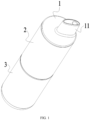
FIG. 1 is a schematic diagram of an aerosol generation device according to an embodiment of this application; -
FIG. 2 is a cross-sectional view of an aerosol generation device according to an embodiment of this application; -
FIG. 3 is another cross-sectional view of an aerosol generation device according to an embodiment of this application; -
FIG. 4 is a schematic diagram of a pod assembly according to another embodiment of this application; -
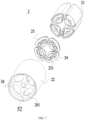
FIG. 5 is a schematic exploded view of a pod assembly according to an embodiment of this application; -
FIG. 6 is another schematic diagram of a pod assembly according to an embodiment of this application; -
FIG. 7 is another schematic exploded view of a pod assembly according to an embodiment of this application; -
FIG. 8 is a schematic diagram of a mouth piece according to an embodiment of this application; -
FIG. 9 is another schematic diagram of a mouth piece according to an embodiment of this application; -
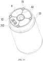
FIG. 10 is a schematic diagram of a power supply assembly according to an embodiment of this application; and -
FIG. 11 is another schematic diagram of a power supply assembly according to an embodiment of this application. - In the accompanying drawings:
- 1. Mouth piece; 11. Suction nozzle; 12. Base plate; 13. Connecting member; 14. Blocking member; 15. Screw;
- 2. Pod assembly; 21. Pod; 211. Accommodating cavity; 212. Atomizer; 213. Air channel tube; 214. Flexible member; 22. Housing; 23. Divider; 24. First electrode set; 25. Mounting base; 251. First air hole; 26. Bottom plate; 261. Through hole;
- 3. Power supply assembly; 31. Battery cell; 32. Second electrode set; 33. Holder; 331. Receiving tube; 332. Second air hole; 333. Mounting groove;
- 4. Stop member; 41. Convex rib;
- 5. Prompt mechanism; 51. First prompt member; 511. Ball; 512. Elastic piece; 513. Fixing cylinder; and 52. Second prompt member.
- The technical solutions in the embodiments of this application are clearly and completely described below with reference to the accompanying drawings in the embodiments of this application. Apparently, the described embodiments are merely some rather than all of the embodiments of this application. Based on the embodiments of this application, all other embodiments obtained by a person of ordinary skill in the art without creative efforts shall fall within the protection scope of this application.
- The terms "first", "second", and "third" in this application are merely intended for a purpose of description, and shall not be understood as indicating or implying relative significance or implicitly indicating a quantity or sequence of indicated technical features. All directional indications (for example, upper, lower, left, right, front, and rear) in the embodiments of this application are merely used for explaining relative position relationships, movement situations, or the like between the various components in a specific posture (as shown in the accompanying drawings). If the specific posture changes, the directional indications change accordingly. In addition, terms "include", "have", and any variations thereof are intended to indicate non-exclusive inclusion. For example, a process, method, system, product, or device that includes a series of steps or units is not limited to the listed steps or units, but further optionally includes a step or unit that is not listed, or further optionally includes another step or component that is intrinsic to the process, method, product, or device.
- "Embodiment" mentioned in this specification means that particular features, structures, or characteristics described with reference to the embodiment may be included in at least one embodiment of this application. The term appearing at different positions of the specification may not refer to the same embodiment or an independent or alternative embodiment that is mutually exclusive with another embodiment. A person skilled in the art explicitly or implicitly understands that the embodiments described in the specification may be combined with other embodiments.
- It should be noted that, when a component is referred to as "being fixed to" another component, the component may be directly on the other component, or an intervening component may be present. When a component is considered to be "connected to" another component, the component may be directly connected to the another component, or one or more intervening component may also be present between them. The terms "vertical", "horizontal", "left", "right", and similar expressions used in this specification are only for purposes of illustration but not indicate a unique implementation.
- Referring to
FIG. 1 to FIG. 3 , an embodiment of this application provides an aerosol generation device. The aerosol generation device includes amouth piece 1, apower supply assembly 3, and apod assembly 2 having a plurality ofpods 21. - The
mouth piece 1 includes abase plate 12 and asuction nozzle 11 connected to thebase plate 12. Thesuction nozzle 11 may be held in a mouth by a user. The user may inhale an aerosol generated by the aerosol generation device by inhaling thesuction nozzle 11. Thebase plate 12 is used for supporting thesuction nozzle 11. Thebase plate 12 may be integrally formed with thesuction nozzle 11. - Each
pod 21 may have anaccommodating cavity 211. Theaccommodating cavity 211 is used for accommodating a liquid substrate that can be atomized to generate the aerosol. A volume of theaccommodating cavity 211 may not exceed 5 ml, for example, the volume of theaccommodating cavity 211 may be approximately 2 ml. - The liquid substrate may include a liquid including tobacco substances containing volatile tobacco flavor components, or may be a liquid including non-tobacco substances. The liquid substrate may include water, medical solution, solvent, ethanol, plant extract, spice, fragrance, vitamin mixture, and the like. The spice may include areca nut extract, menthol, peppermint, spearmint oil, various fruity aroma ingredients, and the like, but is not limited thereto. The fragrance may include components that can provide various aromas or flavors to the user. The vitamin mixture may be a mixture of at least one of vitamin A, vitamin B, vitamin C, and vitamin E, but is not limited thereto. Based on different attributes of the liquid substrate, the aerosol generation device may be used in different fields, such as medical treatment and electronic aerosol atomization.
- The "a plurality of" means two or more. In the embodiment shown in
FIG. 4 , fourpods 21 are provided, but this is not limited thereto. At least two of the plurality ofpods 21 may be used for accommodating different liquid substrates. The different liquid substrates include liquid substrates with different tastes or liquid substrates with different ingredients and ratios, so that the user may be provided with different inhalation experience by switching thepods 21 in communication with themouth piece 1. Certainly, in an embodiment, the liquid substrates accommodated in all thepods 21 may be the same. - Each
pod 21 may further include anatomizer 212. Theatomizer 212 is in fluid communication with theaccommodating cavity 211. Theatomizer 212 is configured to atomize the liquid substrate. Theatomizer 212 may include a liquid absorbing element and a heating element. The liquid absorbing element may be a porous body or a fiber, and can absorb the liquid substrate and guide the liquid substrate into an atomization range of the heating element; and the heating element is configured to atomize at least part of the liquid substrate on the liquid absorbing element into the aerosol. The heating element may be combined on the liquid absorbing element, so that the heating element can be integrally formed with the liquid absorbing element. - Each
pod 21 may further have anair channel tube 213. Theair channel tube 213 provides at least part of an airflow channel in which theatomizer 212 is in fluid communication with themouth piece 1. The aerosol generated by theatomizer 212 enters themouth piece 1 through the airflow channel. Theaccommodating cavity 211 may be arranged around theair channel tube 213, or theair channel tube 213 may be arranged on one side of theaccommodating cavity 211. - In an example, the
pod 21 may include an atomization compartment in fluid communication with theaccommodating cavity 211, theatomizer 212 is accommodated in the atomization compartment, theair channel tube 213 is in fluid communication with the atomization compartment, themouth piece 1 is located above theaccommodating cavity 211, and the atomization compartment is located below theaccommodating cavity 211. - Alternatively, in another example, referring to
FIG. 2 , at least part of theatomizer 212 is arranged in theair channel tube 213. Theair channel tube 213 is provided with a liquid guiding hole. Theatomizer 212 is in fluid communication with theaccommodating cavity 211 through the liquid guiding hole. The liquid substrate in theaccommodating cavity 211 may run through the liquid guiding hole to be absorbed by the liquid absorbing element and atomized by the heating element, or part of the liquid absorbing element may run through the liquid guiding hole into theaccommodating cavity 211 to absorb and guide the liquid substrate. - Referring to
FIG. 2 , eachpod 21 further includes aflexible member 214 having a first air channel. The first air channel is in fluid communication with theatomizer 212 in thepod 21, that is, the first air channel provides at least part of the airflow channel in which theatomizer 212 is in communication with themouth piece 1. In an example, the first air channel is in fluid communication with theair channel tube 213, and the first air channel is in fluid communication with theatomizer 212 through theair channel tube 213. In addition, an upper end of theair channel tube 213 is fixed by theflexible member 214. For example, theair channel tube 213 is in communication with the first air channel while the upper end of theair channel tube 213 is embedded and fixed in theflexible member 214. - At least part of the
flexible member 214 is made of a flexible material. The flexible material includes, but is not limited to, silica gel, rubber, or the like. Therefore, theflexible member 214 can seal an upper end of theaccommodating cavity 211 to prevent the liquid substrate from leaking from above theaccommodating cavity 211. In addition, theflexible member 214 may further be in sealed connection with theair channel tube 213 to help to prevent the liquid substrate from entering the airflow channel. In addition, theflexible member 214 can further prevent external air from entering theaccommodating cavity 211, which is beneficial to preventing oxidization and deterioration of the liquid substrate, and extending a shelf life of the liquid substrate. - In an embodiment, referring to
FIG. 1 andFIG. 2 , thepod assembly 2 is arranged between themouth piece 1 and thepower supply assembly 3. Thepod assembly 2 and thesuction nozzle 11 are located on opposite sides of thebase plate 12, and thepod assembly 2 supports thebase plate 12. Theflexible member 214 of eachpod 21 may in resilient abutment against thebase plate 12, and at least part of theflexible member 214 may protrude beyond an end surface of thepod 21. Therefore, the connection between eachflexible member 214 and themouth piece 1 may be sealed abutment, so that when theatomizer 212 in one or more of thepods 21 is not in fluid communication with thesuction nozzle 11 in themouth piece 1, airflow channels that are not in fluid communication with thesuction nozzle 11 are closed by thebase plate 12, which helps to prevent the external air from entering the airflow channels that are not in fluid communication with thesuction nozzle 11 and then entering theaccommodating cavity 211 through theatomizer 213 in communication with the airflow channels, which is not conducive to preservation of the liquid substrate. In addition, the airflow channels that are not in fluid communication with thesuction nozzle 11 are closed by thebase plate 12, which can reduce natural evaporation of the liquid substrate, and help to reduce loss of the liquid substrate. - When the
atomizer 212 in the one or more of thepods 21 is in fluid communication with thesuction nozzle 11 in themouth piece 1, the sealed abutment between thebase plate 11 and theflexible member 214 can prevent the aerosol generated by theatomizer 213 from leaking. - Referring to
FIG. 4 andFIG. 5 , thepod assembly 2 may further include ahousing 22. The plurality ofpods 21 are all accommodated in thehousing 22. - At least part of the
housing 22 arranged around the plurality ofpods 21 may be transparent, so that thepods 21 in thehousing 22 may be visually observed through thehousing 22. At least part of a wall defining theaccommodating cavity 211 in thepod 21 may also be transparent, so that an interior of thepod 21 may be visually observed through thehousing 22 and the wall defining theaccommodating cavity 211 in sequence. For example, a remaining amount of the liquid substrate in thepod 21 may be observed, to provide a basis for the user to switch thepod 21 in communication with themouth piece 1. It should be noted that, it is optional rather than compulsory that at least part of thehousing 22 arranged around the plurality ofpods 21 is transparent. - Referring to
FIG. 5 , thepod assembly 2 may further include adivider 23 arranged inside thehousing 22. Thedivider 23 may divide an inner space of thehousing 22 into a plurality of positioning spaces. Each positioning space may accommodate at least part of at least onepod 21. A quantity ofdividers 23 may be consistent with a quantity ofpods 21, so that a quantity of positioning spaces formed is consistent with the quantity ofpods 21. Twoadjacent dividers 23 and thehousing 22 may jointly clamp apod 21, thereby helping to maintain thepod 21 in the positioning space. Thedivider 23 may be integrally formed with thehousing 22. Alternatively, thedivider 23 may be formed separately from thehousing 22, and then thedivider 23 is combined into thehousing 22 in a combination manner. - In the embodiment shown in
FIG. 5 , fourdividers 23 are provided, so that four positioning spaces are provided. Fourpods 21 are provided, and each positioning space receives onepod 21. - The
power supply assembly 3 may include anysuitable battery cell 31. In an embodiment, thebattery cell 31 is a lithium-ion battery. Alternatively, thebattery cell 31 may be a nickel-metal hydride battery, a nickel-cadmium battery, or a lithium-based battery, for example, a lithium cobalt battery, a lithium iron phosphate battery, a lithium titanate battery, or a lithium polymer battery. Thepower supply assembly 3 may include a circuit board and one or more control circuits arranged on the circuit board. The control circuit may control output of thebattery cell 31, for example, enable thebattery cell 31 to output an alternating current or a direct current, or enable thebattery cell 31 to output a current or a voltage in the form of a pulse. - The control circuit may include one or more controllers. The controller may control an overall operation of the aerosol generation device. Specifically, the controller controls operations of the battery cell and the pod, and the controller can further control operations of other elements of the aerosol generation device. In addition, the controller may determine whether the aerosol generation device is operable by checking a status of the elements of the aerosol generation device.
- The
power supply assembly 3 is configured to provide power support for theatomizer 212 to atomize the liquid substrate. Based on this, referring toFIG. 6 ,FIG. 7 , andFIG. 10 , thepod assembly 2 further includes a first electrode set 24. A second electrode set 32 is arranged on thepower supply assembly 3. Thepower supply assembly 3 can provide power to the first electrode set 24 electrically connected to the second electrode set 32, thereby providing power to thecorresponding atomizer 212 for atomizing the liquid substrate to generate the aerosol. A plurality of first electrode sets 24 are provided, and theatomizer 212 in eachpod 21 is electrically connected to one of the first electrode sets 24 exclusively. That is, oneatomizer 212 is electrically connected to only one first electrode set 24, and one first electrode set 24 is electrically connected to only oneatomizer 212, so that a plurality ofatomizers 212 are electrically connected to different first electrode sets 24 respectively. A quantity of second electrode sets 32 is less than a quantity of first electrode sets 24, so that thepower supply assembly 3 cannot provide power to allatomizers 212 in thepod assembly 2 simultaneously. - In an embodiment, the
power supply assembly 3 is configured to rotate relative to thepod assembly 2. When thepod assembly 2 rotates relative to thepower supply assembly 3, the first electrode set 24 rotates relative to the second electrode set 32, and at least one second electrode set 32 may be configured to electrically abut against different first electrode sets 24 in turn during 360° rotation of thepod assembly 2 relative to thepower supply assembly 3. Therefore, the first electrode set 24 electrically connected to the second electrode set 32 may be switched by relatively rotating thepod assembly 2 and thepower supply assembly 3. - In an example, referring to
FIG. 10 , only one second electrode set 32 is provided. The second electrode set 32 is configured to be electrically connected to the first electrode set 24 rotated to abut against the second electrode set 32, so that thepower supply assembly 3 can only provide power to theatomizer 212 in one of thepods 21 at a same moment, that is, only onepod 21 can generate the aerosol at the same moment. In this example, themouth piece 1 may be configured to be rotatable relative to thepod assembly 2, so that through rotation of themouth piece 1 relative to thepod assembly 2, themouth piece 1 may select to be in fluid communication with theatomizer 212 in thepod 21 that can generate the aerosol, that is, thepod 21 in fluid communication with themouth piece 1 may be switched through the rotation of themouth piece 1 relative to thepod assembly 2. - It should be noted that, in another example, a plurality of second electrode sets 32 may be provided, and the
mouth piece 1 can also be in airflow communication with theatomizers 212 in the plurality ofpods 21 simultaneously, so that thepower supply assembly 3 can provide power to theatomizers 212 in the plurality ofpods 21 simultaneously, and the user can inhale a mixed aerosol provided by the plurality ofpods 21 from themouth piece 1 simultaneously. For example, when two second electrode sets 32 are provided, the two second electrode sets 32 may electrically abut against two first electrode sets 24 respectively, so that thepower supply assembly 3 provides power to theatomizers 212 in twopods 21 simultaneously, and themouth piece 1 can be in airflow communication with theatomizers 212 in the twopods 21 that can generate the aerosol simultaneously. In this way, the user can inhale the aerosols generated by the twopods 21 from themouth piece 1 simultaneously. - The first electrode set 24 and the second electrode set 32 each include at least two electrodes, for example, each may include at least an anode electrode and a cathode electrode.
- Referring to
FIG. 5 andFIG. 7 , thepod assembly 2 may further include a plurality of mountingbases 25. A quantity of mountingbases 25 may be consistent with the quantity of first electrode sets 24. One first electrode set 24 may be arranged on one mountingbase 25. The first electrode set 24 may be combined on a correspondingpod 21 through the mountingbase 25, so that the first electrode set 24 and the correspondingpod 21 are integrally formed - In the embodiments shown in
FIG. 4 to FIG. 7 , each mountingbase 25 is provided with afirst air hole 251. When the mountingbase 25 is combined on the correspondingpod 21, thefirst air hole 251 is in airflow communication with theair channel tube 213 in thepod 21. When the user inhales thesuction nozzle 11, air enters thepod assembly 2 through thefirst air hole 251, further enters theair channel tube 213, then enters thesuction nozzle 11, and finally enters a mouth of the user. - The
pod assembly 2 may further include abottom plate 26. Thebottom plate 26 is used for supporting thepods 21 accommodated in thehousing 22. Thebottom plate 26 may be integrally formed with thehousing 22. Thebottom plate 26 may be provided with a plurality of throughholes 261. A quantity of throughholes 261 may be consistent with the quantity of mountingbases 25. At least some of the mountingbases 25 may be embedded in corresponding throughholes 261, thereby helping to maintain thepods 21 in thehousing 22 more stably. In addition, the first electrode set 24 arranged on the mountingbase 25 can be exposed through the corresponding throughhole 261, helping to electrically connect the first electrode set 24 to the second electrode set 32. In addition, an edge of the throughhole 261 can limit the mountingbase 25, thereby preventing position offsetting of the first electrode set 24 and shaking of thepod 21 during the process in which the second electrode set 32 switches the first electrode set 24 to which the second electrode set 32 is electrically connected. - In an embodiment, the
power supply assembly 3 and themouth piece 1 are configured to rotate relative to thepod assembly 2 simultaneously. When thepower supply assembly 3 rotates relative to thepod assembly 2, themouth piece 1 rotates relative to thepod assembly 2. Therefore, the first electrode set 24 electrically connected to the second electrode set 32 may be switched through one rotation, so that the second electrode set 32 on thepower supply assembly 3 is switched to be electrically connected to one or more selected first electrode sets 24, and one or moreselected pods 21 can generate the aerosol. Meanwhile, themouth piece 1 may switch thepod 21 in fluid communication or airflow communication with themouth piece 1, so that themouth piece 1 can be switched to be in fluid communication with theatomizer 212 in the one or moreselected pods 21 while the second electrode set 32 is switched to the first electrode set 24. In other words, the one or moreselected pods 21 can be electrically connected to thepower supply assembly 3 and in fluid communication with themouth piece 1 simultaneously without performing two operations or performing two independent rotations. - Based on this, in an example, the aerosol generation device may further include a connecting
member 13 connected to thebase plate 12. The connectingmember 13 is connected to thepower supply assembly 3. Themouth piece 1 and thepower supply assembly 3 may simultaneously rotate relative to thepod assembly 2 under the action of the connectingmember 13. The connectingmember 13 may be a component of themouth piece 1. The connectingmember 13 may be integrally formed with thebase plate 12. By integrally forming the connectingmember 13 and thebase plate 12, a manner of combining the connectingmember 13 and thebase plate 12 can be simplified, which helps to reduce a thickness of thebase plate 12, and is beneficial to miniaturization of the aerosol generation device. Certainly, in another example, the connectingmember 13 may be integrally formed with theholder 33 of thepower supply assembly 3. - To shorten a length of the airflow channel communicating the
atomizer 212 with themouth piece 1, thepod assembly 2 may be arranged between themouth piece 1 and thepower supply assembly 3. In the embodiment shown inFIG. 3 , the connectingmember 13 connected to themouth piece 1 may run through thepod assembly 2 to be connected to thepower supply assembly 3, that is, thepod assembly 2 may rotate around the connectingmember 13. - Referring to
FIG. 2 , thesuction nozzle 11 on themouth piece 1 may be arranged offset from a center of thebase plate 12. When themouth piece 1 is rotated to be in fluid communication with theair channel tube 213 in the selectedpod 21, the air channel and theair channel tube 213 in thesuction nozzle 11 may share a central axis, which helps to shorten an airflow path in which the aerosol is inhaled into the mouth by the user, and further helps to reduce a condensation amount of the aerosol before the aerosol is inhaled into the mouth by the user. - In a longitudinal direction, the
mouth piece 1 is arranged above thepod assembly 2. An upper end of the air channel in thesuction nozzle 11 is an inhalation port, and the aerosol generated by thepod 21 enters the mouth of the user through the inhalation port. An arrangement position of the second electrode set 32 that electrically abuts against the first electrode set 24 of the selectedpod 21 may correspond to the inhalation port of thesuction nozzle 11 in the longitudinal direction. In other words, when the second electrode set 32 electrically abuts against the selectedpod 21, at least part of the second electrode set 32 is located longitudinally below thepod 21. - The
power supply assembly 3 may include aholder 33. Theholder 33 is rotatably connected to thepod assembly 2. The connectingmember 13 is connected to theholder 33. The second electrode set 32 may be fixed on theholder 33. A blockingmember 14 is arranged on the connectingmember 13, and the blockingmember 14 is configured to prevent the connectingmember 13 from disengaging from theholder 33 by abutting against theholder 33, so that the blockingmember 14 can maintain the connection between the connectingmember 13 and theholder 33. - In an embodiment, referring to
FIG. 3 , a receivingtube 331 extending in the longitudinal direction is formed on theholder 33. Themouth piece 1 is located above thepower supply assembly 3. A lower end of the connectingmember 13 is embedded in the receivingtube 331. The blockingmember 14 is arranged below the receivingtube 331. A distance between at least part of an edge of the blockingmember 14 and a central axis of the receivingtube 331 is greater than an inner diameter of the receivingtube 331, or the blockingmember 14 can abut against a lower end of the receivingtube 331, so that the blockingmember 14 cannot enter the receivingtube 331, and therefore the connectingmember 13 cannot be moved upward to disengage from theholder 33. - When the
power supply assembly 3 and thepod assembly 2 are relatively stationary, or when themouth piece 1 and thepod assembly 2 are relatively stationary, the blockingmember 14 may remain against theholder 33. - In the embodiment shown in
FIG. 3 , the blockingmember 14 is a sheet plate, and ascrew 15 runs through the blockingmember 14, then is inserted into the connectingmember 13, and is threadedly connected to the connectingmember 13. Theholder 33 has a cavity. The cavity is located below the receivingtube 331. A lower end of the cavity is open to allow thescrew 15 to enter the cavity, thereby facilitating insertion of thescrew 15 into the connectingmember 13 through the blockingmember 14. - To prevent the connecting
member 13 from rotating relative to the receivingtube 331, in an example, ahole 3311 in the receivingtube 331 for receiving the connectingmember 13 is a non-circular hole; in an example, alower end 131 of the connectingmember 13 for being received by the receivingtube 331 is non-circular; in an example, the blockingmember 14 is non-circular in a radial plane, and a radial edge of the blockingmember 14 is in contact with a wall of theholder 33; and in an example, the wall on theholder 33 that defines the cavity is non-circular, and the radial edge of the blockingmember 14 is in contact with the non-circular wall on theholder 33. - In the embodiment shown in
FIG. 10 , theholder 33 is provided with asecond air hole 332. The second air hole may be provided adjacent to the second electrode set 32, so that when the second electrode set 32 is rotated to be electrically connected to the selected first electrode set 24, thesecond air hole 332 can be in fluid communication with the correspondingfirst air hole 251 on the mountingbase 25. During inhalation, air may enter thefirst air hole 251 through thesecond air hole 332. - Referring to
FIG. 2 andFIG. 3 , thebase plate 12 is rotatably connected to thepod assembly 2, and thebase plate 12 elastically abuts against theflexible member 214 of thepod 21. When themouth piece 1 rotates relative to thepod assembly 2, theflexible member 214 rubs against a lower surface of thebase plate 12, so that theflexible member 214 can provide resistance to the rotation of themouth piece 1 relative to thepod assembly 2, thereby preventing themouth piece 1 from switching thepod 21 in fluid communication with themouth piece 1 in an unexpected case, or preventing themouth piece 1 from rotating in an unexpected case to be out of alignment with the first air channel that needs to be in fluid communication with themouth piece 1. - In an embodiment, under the action of the connecting
member 13, the abutment between theholder 33 and the blockingmember 14 can maintain the connection between themouth piece 1 and thepod assembly 2. Further, an abutment force when the blockingmember 14 and theholder 33 abut against each other pulls thebase plate 12 downward, causing thebase plate 12 to press theflexible member 214 of thepod 21 downward, so that the abutment between theholder 33 and the blockingmember 14 provides a force to bring thebase plate 12 into resilient abutment against theflexible member 214 of thepod 21 or provides a force to bring thebase plate 12 into sealed abutment against theflexible member 214 of thepod 21. - A
stop member 4 may be fixed to at least one of theholder 33 and thepod assembly 2. Thestop member 4 is configured to provide resistance to the rotation of thepod assembly 2 relative to thepower supply assembly 3, to prevent rotation of thepower supply assembly 3 relative to thepod assembly 2 in an unexpected case, help to prevent the second electrode set 32 from switching the first electrode set 24 to which the second electrode set 32 is electrically connected in an unexpected case, and help to ensure that the second electrode set 32 and the selected first electrode set 24 maintain a stable electrical connection. - In an embodiment, referring to
FIG. 2 andFIG. 3 , thestop member 4 is arranged between theholder 33 and thepod assembly 2, and is pressed by theholder 33 and thepod assembly 2. Specifically, thestop member 4 may be pressed by theholder 33 and thebottom plate 26, so that when thepower supply assembly 3 and thepod assembly 2 rotate relative to each other, thestop member 4 can rub against thepower supply assembly 3, or against thepod assembly 2, or against another stop member fixed to thepower supply assembly 3/pod assembly 2, to generate friction that hinders the rotation of thepower supply assembly 3 relative to thepod assembly 2. The friction generated by the rubbing of thestop member 4 is at least part of the resistance to the rotation of thepod assembly 2 relative to thepower supply assembly 3. - In an example, the friction between the
flexible member 214 and thebase plate 12 and/or the friction provided by the rubbing of thestop member 4 forms the resistance to the rotation of thepod assembly 2 relative to thepower supply assembly 3. Therefore, an operation on the aerosol generation device by the user may be simplified. When themouth piece 1 and/or thepower supply assembly 3 needs to rotate relative to thepod assembly 2, the user only needs to perform an action of overcoming against the friction to rotate themouth piece 1 and/or thepower supply assembly 3 relative to thepod assembly 2. There is no need for the user to perform an action of driving themouth piece 1 and/or thepower supply assembly 3 to rotate relative to thepod assembly 2 after performing the action of unlocking themouth piece 1 and/or thepower supply assembly 3 from thepod assembly 2. - In an example, under the action of the connecting
member 13, the abutment between theholder 33 and the blockingmember 14 can maintain the connection between thepower supply assembly 3 and thepod assembly 2. Further, the abutment force when the blockingmember 14 and theholder 33 abut against each other enables theholder 33 and thebottom plate 26 to approach each other, so that thebottom plate 26 and theholder 33 jointly press thestop member 4. Therefore, the abutment between theholder 33 and the blockingmember 14 provides a force for theholder 33 and thepod assembly 2 to press thestop member 4, so that thestop member 4 can rub to generate friction. That is, the abutment between theholder 33 and the blockingmember 14 can provide resistance to the rotation of thepod assembly 2 relative to thepower supply assembly 3. - In an example, the
stop member 4 is elastic. Therefore, thestop member 4 may include silica gel, rubber, sponge, or another elastic material. Theelastic stop member 4 may be in an elastic compression state under the press of thepower supply assembly 3 and thepod assembly 2, to increase the friction generated by the rubbing of thestop member 4. In addition, theelastic stop member 4 can protect thebottom plate 26 of thepod assembly 2 and theholder 33 of thepower supply assembly 3, and prevent thebottom plate 26 and theholder 33 from being worn by direct frictional contact, which helps to maintain the stable resistance to the rotation of thepod assembly 2 relative to thepower supply assembly 3 during long-term use of the aerosol generation device. - In an example, to prevent excessive resistance when the
power supply assembly 3 rotates relative to thepod assembly 2, aconvex rib 41 may be formed on thestop member 4, and theconvex rib 41 abuts against thebottom plate 26. Theconvex rib 41 can reduce an area of a friction surface on which thestop member 4 rubs. In the embodiments shown inFIG. 10 andFIG. 11 , thestop member 4 is fixed to theholder 33. During the rotation of thepower supply assembly 3 relative to thepod assembly 2, theconvex rib 41 on a surface of thestop member 4 facing thebottom plate 26 contacts and rubs against thebottom plate 26, generating friction that hinders the rotation of thepower supply assembly 3 relative to thepod assembly 2. In this embodiment, preferably, thestop member 4 is elastic. - Referring to
FIG. 3 ,FIG. 10 , andFIG. 11 , the aerosol generation device may further include a prompt mechanism 5. During rotation, when the second electrode set 32 is rotated to be electrically connected to any one of the first electrode sets 24 in thepod assembly 2, or when themouth piece 1 is rotated to be in airflow communication with any one of thepods 21 in thepod assembly 2, the prompt mechanism 5 sends a prompt signal. The prompt mechanism 5 can provide a haptic feedback. The prompt signal may include a sound signal, a light signal, a vibration signal, or the like. After sensing the prompt signal, the user may stop thepower supply assembly 3 and/or themouth piece 1 from continuing to rotate relative to thepod assembly 2. - In an embodiment, the prompt mechanism 5 includes a first
prompt member 51 and a secondprompt member 52. The secondprompt member 52 is arranged on thepod assembly 2. More specifically, referring toFIG. 6 andFIG. 7 , the secondprompt member 52 may be arranged on thehousing 22 or thebottom plate 26, and the firstprompt member 51 may be arranged on thebase plate 12 of themouth piece 1 or may be arranged on theholder 33 of thepower supply assembly 3. During rotation, when the firstprompt member 51 and the secondprompt member 52 are combined or facing each other, the prompt mechanism 5 sends the prompt signal. - A quantity of at least one of the first
prompt members 51 and the secondprompt members 52 may be consistent with the quantity ofpods 21 or the quantity of first electrode sets 24. A quantity of the other may be not less than 1 and not greater than the quantity ofpods 21 or not greater than the quantity of first electrode sets 24. - In the embodiment shown in
FIG. 3 , the firstprompt member 51 includes aball 511 arranged on theholder 33, theball 511 may be rollably combined with theholder 33 and is partially exposed outside theholder 33, the secondprompt member 52 includes a recessed portion arranged on thebottom plate 26, and theball 511 may remain in contact with thebottom plate 26, so that when thepower supply assembly 3 and thepod assembly 2 rotate relative to each other, theball 511 can roll. When theball 511 rolls to enter the recessed portion, the prompt mechanism 5 generates the prompt signal. The prompt signal may be a vibration generated when theball 511 enters the recessed portion, a click sound generated when theball 511 enters the recessed portion, or the like. It should be noted that, in other embodiments, theball 511 may be arranged on thehousing 22 or thebottom plate 26, and the recessed portion may be correspondingly arranged on theholder 33. When thepower supply assembly 3 and thepod assembly 2 rotate relative to each other, theball 511 can roll. When theball 511 rolls to enter the recessed portion, the prompt mechanism 5 generates the prompt signal. - In the embodiments shown in
FIG. 6 andFIG. 10 , the quantity of firstprompt members 51 is the same as the quantity of secondprompt members 52, or a quantity ofballs 511 is the same as a quantity of recessed portions. - To enhance the prompt signal, in an embodiment, referring to
FIG. 3 , the firstprompt member 51 may further include anelastic piece 512 supporting theball 511. Theelastic piece 512 may be an elastic member such as a spring, silica gel, or rubber. During rolling of theball 511, theelastic piece 512 is in the elastic compression state. Therefore, when theball 511 rolls to enter the recessed portion, the prompt mechanism 5 can generate a greater vibration or generate a greater click sound. More specifically, referring toFIG. 3 , the firstprompt member 51 may further include a fixingcylinder 513 with a closed bottom portion. An opening of the fixingcylinder 513 arranged opposite to the closed bottom portion of the fixingcylinder 513 has an aperture less than a sphere diameter of theball 511. Theelastic piece 512 is arranged between the bottom portion of the fixingcylinder 513 and theball 511. Under the support of theelastic piece 512, part of theball 511 protrudes out of the opening of the fixingcylinder 513. Amountinggroove 333 is provided on theholder 33 of thepower supply assembly 3, and the fixingcylinder 513 is embedded and fixed in the mountinggroove 333. Theelastic piece 512 may be always in the elastic compression state. - It may be understood that in other embodiments, during rotation, when the second electrode set 32 is rotated to be electrically connected to any one of the first electrode sets 24 in the
pod assembly 2, or when themouth piece 1 is rotated to be in airflow communication with any one of thepods 21 in thepod assembly 2, the prompt mechanism 5 can generate a change in an electrical parameter or a magnetic parameter. When detecting the change in the electrical parameter or the magnetic parameter, the circuit board controls an indication element such as a buzzer, a player, an LED light, or a vibrator to send a prompt. - The aerosol generation device may further include a control switch electrically connected to the
power supply assembly 3. The control switch is configured to control thepower supply assembly 3 to be electrically connected to theatomizer 212 in the selectedpod 21, so that theatomizer 212 in thepod 21 that is electrically connected to thepower supply assembly 3 can work to atomize the aerosol generated by the liquid substrate in thepod 21. The otherunselected pods 21 in thepod assembly 2 are in a state of being electrically disconnected from thepower supply assembly 3. - In an embodiment, the control switch includes a manual switch. Specifically, after the second electrode set 32 is electrically connected to the selected first electrode set 24, the user may operate the control switch, so that the
battery cell 31 in thepower supply assembly 3 provides power to the first electrode set 24 through the second electrode set 32. The control switch may be a key switch, a slide switch, a touch switch, a touch screen, a remote control switch, or the like. Certainly, the user may operate the control switch, so that when the second electrode set 32 remains electrically connected to the selected first electrode set 24, thepower supply assembly 3 is not electrically conductive to theatomizer 212 of the selectedpod 21 or a circuit between thepower supply assembly 3 and theatomizer 212 of the selectedpod 21 is cut off. - In an embodiment, the control switch includes a first electrode set 24 and a second electrode set 32. When the second electrode set 32 is electrically connected to the selected first electrode set 24, the control switch formed by the second electrode set 32 and the selected first electrode set 24 is turned on, and the
battery cell 31 in thepower supply assembly 3 automatically provides power to the first electrode set 24 through the second electrode set 32. - In an embodiment, an air inlet channel communicating the outside and the
second air hole 332 is arranged in thepower supply assembly 3. The control switch includes a pneumatic switch. The pneumatic switch is arranged in the air inlet channel, or a mounting chamber of the pneumatic switch is in airflow communication with the air inlet channel. The pneumatic switch can detect a speed of an airflow in the air inlet channel or the mounting chamber, or detect an air pressure in the air inlet channel or the mounting chamber, and determine whether the user is inhaling thesuction nozzle 11 based on the speed of airflow and the air pressure. If it is determined that the user is inhaling thesuction nozzle 11, the pneumatic switch sends a control signal to the circuit board. The control circuit in the circuit board receives the control signal to control thebattery cell 31 to provide power to the second electrode set 32. Therefore, thebattery cell 31 can provide, through the second electrode set and the selected first electrode set 24, power to theatomizer 212 in the selectedpod 21 to atomize the liquid substrate. For example, the pneumatic switch is an air pressure sensor or an airflow sensor. - Based on this, in an example, a plurality of, for example, four,
first air holes 251 in airflow communication with thesecond air hole 332 and theair channel tube 213 are provided, and only onesecond air hole 332 is provided. Theconvex rib 41 on thestop member 4 defines one or more annular regions, and thesecond air hole 332 is provided in one of the annular regions. The abutment between theconvex rib 41 and thebottom plate 26 is sealed abutment. Therefore, when the second electrode set 32 is rotated to be electrically connected to the selected first electrode set 24, the air passing from the air inlet channel through thesecond air hole 332 can only or mainly enter thefirst air hole 251 on the mountingbase 25 of the selected first electrode set 24. It is helpful to increase detection sensitivity of the pneumatic switch. - It should be noted that, the specification of this application and the accompanying drawings thereof illustrate preferred embodiments of this application, but are not limited to the embodiments described in this specification, furthermore, a person of ordinary skill in the art may make improvements or modifications according to the foregoing description, and all the improvements and modifications shall fall within the protection scope of the attached claims of this application.
Claims (14)
- An aerosol generation device, comprising:a mouth piece (1);a pod assembly (2), comprising a plurality of pods (21) independent of each other, each pod (21) comprising an accommodating cavity (211) for accommodating a liquid substrate, an atomizer (212) configured to atomize the liquid substrate, and a first electrode set (24) electrically connected to the atomizer (212); anda power supply assembly (3), on which a second electrode set (32) is arranged, the second electrode set (32) being selectively conductive to the first electrode set (24), wherein:the mouth piece (1) is fixedly connected to the power supply assembly (3),the pod assembly (2) is located between the mouth piece (1) and the power supply assembly (3), andthe pod assembly (2) is configured to be rotatable relative to the mouth piece (1) and the power supply assembly (3) simultaneously, to select at least one of the pods (21) though rotation, so that the atomizer (212) in the pod (21) is in fluid communication with the mouth piece (1) and the first electrode set (24) in the pod (21) is conductive to the second electrode set (32).
- The aerosol generation device according to claim 1, wherein only one second electrode set (32) is provided.
- The aerosol generation device according to claim 1, wherein:the mouth piece (1) comprises a base plate (12) rotatably connected to the pod assembly (2), a suction nozzle (11) on one side of the base plate (12), and a connecting member (13) on another side of the base plate (12), andthe connecting member (13) extends toward the power supply assembly (3) and is connected to the power supply assembly (3).
- The aerosol generation device according to claim 3, wherein:the connecting member (13) and the base plate (12) are integrally formed; orthe suction nozzle (11), the base plate (12), and the connecting member (13) are integrally formed.
- The aerosol generation device according to claim 3, wherein:the pod assembly (2) is configured to rotate around a central axis of the connecting member (13); andthe plurality of pods (21) are arranged around the connecting member (13).
- The aerosol generation device according to claim 3, wherein:the power supply assembly (3) comprises a holder (33) rotatably connected to the pod assembly (2); andthe connecting member (13) runs through the pod assembly (2) to be connected to the holder (33).
- The aerosol generation device according to claim 6, wherein:at least one of the holder (33) and the pod assembly (2) is provided with a stop member; andthe stop member is configured to provide resistance to rotation of the pod assembly (2) relative to the power supply assembly (3).
- The aerosol generation device according to claim 7, wherein:the stop member is elastic; andthe stop member is arranged between the holder (33) and the pod assembly (2) and is pressed by the holder (33) and the pod assembly (2), so that the stop member provides friction to the pod assembly (2) when the power supply assembly (3) and the pod assembly (2) rotate relative to each other.
- The aerosol generation device according to claim 6, wherein:the pod (21) further comprises a flexible member (214) having a first air channel;the first air channel is in fluid communication with the atomizer (212) in the pod (21); andthe base plate (12) in sealed abutment against the flexible member (214).
- The aerosol generation device according to claim 9, wherein at least part of the flexible member (214) protrudes beyond an end surface of the pod (21).
- The aerosol generation device according to claim 3, wherein the suction nozzle (11) is arranged offset from a center of the base plate (12).
- The aerosol generation device according to claim 11, wherein an arrangement position of the second electrode set (32) corresponds to a suction opening of the suction nozzle (11) in a longitudinal direction.
- The aerosol generation device according to claim 1, wherein:the aerosol generation device further comprises a prompt mechanism (5); andthe prompt mechanism (5) is configured to provide an indication when the mouth piece (1) is in fluid communication with the atomizer (212) of any one of the pods (21).
- The aerosol generation device according to claim 13, wherein:the prompt mechanism (5) comprises a ball (511) and a recessed portion;one of the ball (511) and the recessed portion is arranged on the power supply assembly (3) and the other is arranged on the pod assembly (2); andwhen the power supply assembly (3) and the pod assembly (2) rotate relative to each other, the indication is provided when the ball (511) enters or exits the recessed portion.
Applications Claiming Priority (1)
| Application Number | Priority Date | Filing Date | Title |
|---|---|---|---|
| CN202322138076.8U CN221284669U (en) | 2023-08-09 | 2023-08-09 | Aerosol generating device |
Publications (1)
| Publication Number | Publication Date |
|---|---|
| EP4505886A1 true EP4505886A1 (en) | 2025-02-12 |
Family
ID=91736549
Family Applications (1)
| Application Number | Title | Priority Date | Filing Date |
|---|---|---|---|
| EP24193175.7A Pending EP4505886A1 (en) | 2023-08-09 | 2024-08-06 | Aerosol generation device |
Country Status (2)
| Country | Link |
|---|---|
| EP (1) | EP4505886A1 (en) |
| CN (1) | CN221284669U (en) |
Citations (4)
| Publication number | Priority date | Publication date | Assignee | Title |
|---|---|---|---|---|
| US20160366940A1 (en) * | 2014-02-28 | 2016-12-22 | Kimree Hi-Tech Inc. | Electronic cigarette and electronic cigarette atomization control method |
| US20200329779A1 (en) * | 2019-04-19 | 2020-10-22 | Frank Gatski | Multi-chamber cartridge for vaping device and vaping device configured to operate with multi-chamber cartridge |
| US20210177057A1 (en) * | 2019-12-12 | 2021-06-17 | Tuanfang Liu | Electronic cigarette |
| US20230143680A1 (en) * | 2020-09-02 | 2023-05-11 | Kt&G Corporation | Aerosol delivering device and aerosol generating device including the same |
-
2023
- 2023-08-09 CN CN202322138076.8U patent/CN221284669U/en active Active
-
2024
- 2024-08-06 EP EP24193175.7A patent/EP4505886A1/en active Pending
Patent Citations (4)
| Publication number | Priority date | Publication date | Assignee | Title |
|---|---|---|---|---|
| US20160366940A1 (en) * | 2014-02-28 | 2016-12-22 | Kimree Hi-Tech Inc. | Electronic cigarette and electronic cigarette atomization control method |
| US20200329779A1 (en) * | 2019-04-19 | 2020-10-22 | Frank Gatski | Multi-chamber cartridge for vaping device and vaping device configured to operate with multi-chamber cartridge |
| US20210177057A1 (en) * | 2019-12-12 | 2021-06-17 | Tuanfang Liu | Electronic cigarette |
| US20230143680A1 (en) * | 2020-09-02 | 2023-05-11 | Kt&G Corporation | Aerosol delivering device and aerosol generating device including the same |
Also Published As
| Publication number | Publication date |
|---|---|
| CN221284669U (en) | 2024-07-09 |
Similar Documents
| Publication | Publication Date | Title |
|---|---|---|
| CN220274894U (en) | aerosol generating device | |
| CN220109154U (en) | Aerosol generating device | |
| CN113507854B (en) | Aerosol delivery device and aerosol generating device having an aerosol delivery device | |
| EP4527218A2 (en) | Aerosol generation device | |
| US20190307974A1 (en) | Cartridge, atomizer and electronic cigarette having the same | |
| US20230143680A1 (en) | Aerosol delivering device and aerosol generating device including the same | |
| KR102631935B1 (en) | Aerosol generating device comprising a cartridge | |
| CN217826790U (en) | Press rotary type aerial fog generating device | |
| CN222109279U (en) | Aerosol generating device | |
| CN221670983U (en) | Aerosol generating device | |
| CN221284669U (en) | Aerosol generating device | |
| WO2025161930A1 (en) | Aerosol generation apparatus and atomizer | |
| CN220875920U (en) | Aerosol generating device | |
| CN222303089U (en) | Aerosol generating device | |
| CN223968670U (en) | Electronic atomizing device | |
| CN223298563U (en) | Aerosol generating device | |
| CN223968636U (en) | Aerosol generating device and battery assembly for use in combination with a nebulizer | |
| CN223968638U (en) | Aerosol generating device and battery assembly for an aerosol generating device | |
| CN221284670U (en) | Electronic atomization device | |
| CN120419709A (en) | Aerosol generating device | |
| WO2025103354A1 (en) | Aerosol-generating device | |
| CN223873287U (en) | Atomizer and aerosol-generating device | |
| CN223585259U (en) | Atomizing device | |
| CN223515763U (en) | Electronic atomizing device | |
| CN221284687U (en) | Aerosol generating device |
Legal Events
| Date | Code | Title | Description |
|---|---|---|---|
| PUAI | Public reference made under article 153(3) epc to a published international application that has entered the european phase |
Free format text: ORIGINAL CODE: 0009012 |
|
| STAA | Information on the status of an ep patent application or granted ep patent |
Free format text: STATUS: REQUEST FOR EXAMINATION WAS MADE |
|
| 17P | Request for examination filed |
Effective date: 20240806 |
|
| AK | Designated contracting states |
Kind code of ref document: A1 Designated state(s): AL AT BE BG CH CY CZ DE DK EE ES FI FR GB GR HR HU IE IS IT LI LT LU LV MC ME MK MT NL NO PL PT RO RS SE SI SK SM TR |