EP4504469B1 - A dry-forming mould system and a method for manufacturing a cellulose product in a dry-forming mould system - Google Patents
A dry-forming mould system and a method for manufacturing a cellulose product in a dry-forming mould system Download PDFInfo
- Publication number
- EP4504469B1 EP4504469B1 EP23710851.9A EP23710851A EP4504469B1 EP 4504469 B1 EP4504469 B1 EP 4504469B1 EP 23710851 A EP23710851 A EP 23710851A EP 4504469 B1 EP4504469 B1 EP 4504469B1
- Authority
- EP
- European Patent Office
- Prior art keywords
- mould part
- forming
- mould
- cellulose
- dry
- Prior art date
- Legal status (The legal status is an assumption and is not a legal conclusion. Google has not performed a legal analysis and makes no representation as to the accuracy of the status listed.)
- Active
Links
Images








Classifications
-
- B—PERFORMING OPERATIONS; TRANSPORTING
- B26—HAND CUTTING TOOLS; CUTTING; SEVERING
- B26F—PERFORATING; PUNCHING; CUTTING-OUT; STAMPING-OUT; SEVERING BY MEANS OTHER THAN CUTTING
- B26F1/00—Perforating; Punching; Cutting-out; Stamping-out; Apparatus therefor
- B26F1/38—Cutting-out; Stamping-out
- B26F1/44—Cutters therefor; Dies therefor
-
- B—PERFORMING OPERATIONS; TRANSPORTING
- B26—HAND CUTTING TOOLS; CUTTING; SEVERING
- B26D—CUTTING; DETAILS COMMON TO MACHINES FOR PERFORATING, PUNCHING, CUTTING-OUT, STAMPING-OUT OR SEVERING
- B26D7/00—Details of apparatus for cutting, cutting-out, stamping-out, punching, perforating, or severing by means other than cutting
- B26D7/26—Means for mounting or adjusting the cutting member; Means for adjusting the stroke of the cutting member
-
- B—PERFORMING OPERATIONS; TRANSPORTING
- B27—WORKING OR PRESERVING WOOD OR SIMILAR MATERIAL; NAILING OR STAPLING MACHINES IN GENERAL
- B27N—MANUFACTURE BY DRY PROCESSES OF ARTICLES, WITH OR WITHOUT ORGANIC BINDING AGENTS, MADE FROM PARTICLES OR FIBRES CONSISTING OF WOOD OR OTHER LIGNOCELLULOSIC OR LIKE ORGANIC MATERIAL
- B27N3/00—Manufacture of substantially flat articles, e.g. boards, from particles or fibres
- B27N3/08—Moulding or pressing
-
- B—PERFORMING OPERATIONS; TRANSPORTING
- B27—WORKING OR PRESERVING WOOD OR SIMILAR MATERIAL; NAILING OR STAPLING MACHINES IN GENERAL
- B27N—MANUFACTURE BY DRY PROCESSES OF ARTICLES, WITH OR WITHOUT ORGANIC BINDING AGENTS, MADE FROM PARTICLES OR FIBRES CONSISTING OF WOOD OR OTHER LIGNOCELLULOSIC OR LIKE ORGANIC MATERIAL
- B27N3/00—Manufacture of substantially flat articles, e.g. boards, from particles or fibres
- B27N3/08—Moulding or pressing
- B27N3/10—Moulding of mats
- B27N3/14—Distributing or orienting the particles or fibres
-
- B—PERFORMING OPERATIONS; TRANSPORTING
- B27—WORKING OR PRESERVING WOOD OR SIMILAR MATERIAL; NAILING OR STAPLING MACHINES IN GENERAL
- B27N—MANUFACTURE BY DRY PROCESSES OF ARTICLES, WITH OR WITHOUT ORGANIC BINDING AGENTS, MADE FROM PARTICLES OR FIBRES CONSISTING OF WOOD OR OTHER LIGNOCELLULOSIC OR LIKE ORGANIC MATERIAL
- B27N5/00—Manufacture of non-flat articles
-
- B—PERFORMING OPERATIONS; TRANSPORTING
- B29—WORKING OF PLASTICS; WORKING OF SUBSTANCES IN A PLASTIC STATE IN GENERAL
- B29C—SHAPING OR JOINING OF PLASTICS; SHAPING OF MATERIAL IN A PLASTIC STATE, NOT OTHERWISE PROVIDED FOR; AFTER-TREATMENT OF THE SHAPED PRODUCTS, e.g. REPAIRING
- B29C39/00—Shaping by casting, i.e. introducing the moulding material into a mould or between confining surfaces without significant moulding pressure; Apparatus therefor
- B29C39/22—Component parts, details or accessories; Auxiliary operations
- B29C39/26—Moulds or cores
- B29C39/30—Moulds or cores with means for cutting the article
-
- B—PERFORMING OPERATIONS; TRANSPORTING
- B29—WORKING OF PLASTICS; WORKING OF SUBSTANCES IN A PLASTIC STATE IN GENERAL
- B29C—SHAPING OR JOINING OF PLASTICS; SHAPING OF MATERIAL IN A PLASTIC STATE, NOT OTHERWISE PROVIDED FOR; AFTER-TREATMENT OF THE SHAPED PRODUCTS, e.g. REPAIRING
- B29C51/00—Shaping by thermoforming, i.e. shaping sheets or sheet like preforms after heating, e.g. shaping sheets in matched moulds or by deep-drawing; Apparatus therefor
- B29C51/26—Component parts, details or accessories; Auxiliary operations
- B29C51/30—Moulds
- B29C51/32—Moulds having cutting means
-
- B—PERFORMING OPERATIONS; TRANSPORTING
- B29—WORKING OF PLASTICS; WORKING OF SUBSTANCES IN A PLASTIC STATE IN GENERAL
- B29C—SHAPING OR JOINING OF PLASTICS; SHAPING OF MATERIAL IN A PLASTIC STATE, NOT OTHERWISE PROVIDED FOR; AFTER-TREATMENT OF THE SHAPED PRODUCTS, e.g. REPAIRING
- B29C70/00—Shaping composites, i.e. plastics material comprising reinforcements, fillers or preformed parts, e.g. inserts
- B29C70/68—Shaping composites, i.e. plastics material comprising reinforcements, fillers or preformed parts, e.g. inserts by incorporating or moulding on preformed parts, e.g. inserts or layers, e.g. foam blocks
- B29C70/74—Moulding material on a relatively small portion of the preformed part, e.g. outsert moulding
- B29C70/742—Forming a hollow body around the preformed part
-
- B—PERFORMING OPERATIONS; TRANSPORTING
- B29—WORKING OF PLASTICS; WORKING OF SUBSTANCES IN A PLASTIC STATE IN GENERAL
- B29C—SHAPING OR JOINING OF PLASTICS; SHAPING OF MATERIAL IN A PLASTIC STATE, NOT OTHERWISE PROVIDED FOR; AFTER-TREATMENT OF THE SHAPED PRODUCTS, e.g. REPAIRING
- B29C70/00—Shaping composites, i.e. plastics material comprising reinforcements, fillers or preformed parts, e.g. inserts
- B29C70/68—Shaping composites, i.e. plastics material comprising reinforcements, fillers or preformed parts, e.g. inserts by incorporating or moulding on preformed parts, e.g. inserts or layers, e.g. foam blocks
- B29C70/74—Moulding material on a relatively small portion of the preformed part, e.g. outsert moulding
- B29C70/76—Moulding on edges or extremities of the preformed part
- B29C70/763—Moulding on edges or extremities of the preformed part the edges being disposed in a substantial flat plane
-
- B—PERFORMING OPERATIONS; TRANSPORTING
- B30—PRESSES
- B30B—PRESSES IN GENERAL
- B30B9/00—Presses specially adapted for particular purposes
- B30B9/28—Presses specially adapted for particular purposes for forming shaped articles
-
- B—PERFORMING OPERATIONS; TRANSPORTING
- B31—MAKING ARTICLES OF PAPER, CARDBOARD OR MATERIAL WORKED IN A MANNER ANALOGOUS TO PAPER; WORKING PAPER, CARDBOARD OR MATERIAL WORKED IN A MANNER ANALOGOUS TO PAPER
- B31B—MAKING CONTAINERS OF PAPER, CARDBOARD OR MATERIAL WORKED IN A MANNER ANALOGOUS TO PAPER
- B31B50/00—Making rigid or semi-rigid containers, e.g. boxes or cartons
- B31B50/14—Cutting, e.g. perforating, punching, slitting or trimming
- B31B50/20—Cutting sheets or blanks
-
- B—PERFORMING OPERATIONS; TRANSPORTING
- B31—MAKING ARTICLES OF PAPER, CARDBOARD OR MATERIAL WORKED IN A MANNER ANALOGOUS TO PAPER; WORKING PAPER, CARDBOARD OR MATERIAL WORKED IN A MANNER ANALOGOUS TO PAPER
- B31B—MAKING CONTAINERS OF PAPER, CARDBOARD OR MATERIAL WORKED IN A MANNER ANALOGOUS TO PAPER
- B31B50/00—Making rigid or semi-rigid containers, e.g. boxes or cartons
- B31B50/59—Shaping sheet material under pressure
- B31B50/592—Shaping sheet material under pressure using punches or dies
-
- B—PERFORMING OPERATIONS; TRANSPORTING
- B26—HAND CUTTING TOOLS; CUTTING; SEVERING
- B26D—CUTTING; DETAILS COMMON TO MACHINES FOR PERFORATING, PUNCHING, CUTTING-OUT, STAMPING-OUT OR SEVERING
- B26D7/00—Details of apparatus for cutting, cutting-out, stamping-out, punching, perforating, or severing by means other than cutting
- B26D7/26—Means for mounting or adjusting the cutting member; Means for adjusting the stroke of the cutting member
- B26D2007/2607—Means for mounting or adjusting the cutting member; Means for adjusting the stroke of the cutting member for mounting die cutters
-
- B—PERFORMING OPERATIONS; TRANSPORTING
- B26—HAND CUTTING TOOLS; CUTTING; SEVERING
- B26F—PERFORATING; PUNCHING; CUTTING-OUT; STAMPING-OUT; SEVERING BY MEANS OTHER THAN CUTTING
- B26F1/00—Perforating; Punching; Cutting-out; Stamping-out; Apparatus therefor
- B26F1/38—Cutting-out; Stamping-out
- B26F1/44—Cutters therefor; Dies therefor
- B26F2001/4427—Cutters therefor; Dies therefor combining cutting and forming operations
-
- B—PERFORMING OPERATIONS; TRANSPORTING
- B26—HAND CUTTING TOOLS; CUTTING; SEVERING
- B26F—PERFORATING; PUNCHING; CUTTING-OUT; STAMPING-OUT; SEVERING BY MEANS OTHER THAN CUTTING
- B26F1/00—Perforating; Punching; Cutting-out; Stamping-out; Apparatus therefor
- B26F1/38—Cutting-out; Stamping-out
- B26F1/44—Cutters therefor; Dies therefor
- B26F2001/4463—Methods and devices for rule setting, fixation, preparing cutting dies
-
- B—PERFORMING OPERATIONS; TRANSPORTING
- B27—WORKING OR PRESERVING WOOD OR SIMILAR MATERIAL; NAILING OR STAPLING MACHINES IN GENERAL
- B27N—MANUFACTURE BY DRY PROCESSES OF ARTICLES, WITH OR WITHOUT ORGANIC BINDING AGENTS, MADE FROM PARTICLES OR FIBRES CONSISTING OF WOOD OR OTHER LIGNOCELLULOSIC OR LIKE ORGANIC MATERIAL
- B27N3/00—Manufacture of substantially flat articles, e.g. boards, from particles or fibres
- B27N3/08—Moulding or pressing
- B27N3/18—Auxiliary operations, e.g. preheating, humidifying, cutting-off
-
- B—PERFORMING OPERATIONS; TRANSPORTING
- B27—WORKING OR PRESERVING WOOD OR SIMILAR MATERIAL; NAILING OR STAPLING MACHINES IN GENERAL
- B27N—MANUFACTURE BY DRY PROCESSES OF ARTICLES, WITH OR WITHOUT ORGANIC BINDING AGENTS, MADE FROM PARTICLES OR FIBRES CONSISTING OF WOOD OR OTHER LIGNOCELLULOSIC OR LIKE ORGANIC MATERIAL
- B27N3/00—Manufacture of substantially flat articles, e.g. boards, from particles or fibres
- B27N3/08—Moulding or pressing
- B27N3/20—Moulding or pressing characterised by using platen-presses
- B27N3/203—Moulding or pressing characterised by using platen-presses with heating or cooling means
-
- B—PERFORMING OPERATIONS; TRANSPORTING
- B27—WORKING OR PRESERVING WOOD OR SIMILAR MATERIAL; NAILING OR STAPLING MACHINES IN GENERAL
- B27N—MANUFACTURE BY DRY PROCESSES OF ARTICLES, WITH OR WITHOUT ORGANIC BINDING AGENTS, MADE FROM PARTICLES OR FIBRES CONSISTING OF WOOD OR OTHER LIGNOCELLULOSIC OR LIKE ORGANIC MATERIAL
- B27N3/00—Manufacture of substantially flat articles, e.g. boards, from particles or fibres
- B27N3/08—Moulding or pressing
- B27N3/20—Moulding or pressing characterised by using platen-presses
- B27N3/206—Moulding or pressing characterised by using platen-presses for continuous boards
-
- B—PERFORMING OPERATIONS; TRANSPORTING
- B27—WORKING OR PRESERVING WOOD OR SIMILAR MATERIAL; NAILING OR STAPLING MACHINES IN GENERAL
- B27N—MANUFACTURE BY DRY PROCESSES OF ARTICLES, WITH OR WITHOUT ORGANIC BINDING AGENTS, MADE FROM PARTICLES OR FIBRES CONSISTING OF WOOD OR OTHER LIGNOCELLULOSIC OR LIKE ORGANIC MATERIAL
- B27N5/00—Manufacture of non-flat articles
- B27N5/02—Hollow articles
-
- B—PERFORMING OPERATIONS; TRANSPORTING
- B29—WORKING OF PLASTICS; WORKING OF SUBSTANCES IN A PLASTIC STATE IN GENERAL
- B29C—SHAPING OR JOINING OF PLASTICS; SHAPING OF MATERIAL IN A PLASTIC STATE, NOT OTHERWISE PROVIDED FOR; AFTER-TREATMENT OF THE SHAPED PRODUCTS, e.g. REPAIRING
- B29C43/00—Compression moulding, i.e. applying external pressure to flow the moulding material; Apparatus therefor
- B29C43/32—Component parts, details or accessories; Auxiliary operations
- B29C43/36—Moulds for making articles of definite length, i.e. discrete articles
- B29C43/40—Moulds for making articles of definite length, i.e. discrete articles with means for cutting the article
- B29C2043/403—Moulds for making articles of definite length, i.e. discrete articles with means for cutting the article knife blades
-
- B—PERFORMING OPERATIONS; TRANSPORTING
- B29—WORKING OF PLASTICS; WORKING OF SUBSTANCES IN A PLASTIC STATE IN GENERAL
- B29C—SHAPING OR JOINING OF PLASTICS; SHAPING OF MATERIAL IN A PLASTIC STATE, NOT OTHERWISE PROVIDED FOR; AFTER-TREATMENT OF THE SHAPED PRODUCTS, e.g. REPAIRING
- B29C2791/00—Shaping characteristics in general
- B29C2791/001—Shaping in several steps
-
- B—PERFORMING OPERATIONS; TRANSPORTING
- B29—WORKING OF PLASTICS; WORKING OF SUBSTANCES IN A PLASTIC STATE IN GENERAL
- B29C—SHAPING OR JOINING OF PLASTICS; SHAPING OF MATERIAL IN A PLASTIC STATE, NOT OTHERWISE PROVIDED FOR; AFTER-TREATMENT OF THE SHAPED PRODUCTS, e.g. REPAIRING
- B29C2791/00—Shaping characteristics in general
- B29C2791/002—Making articles of definite length, i.e. discrete articles
-
- B—PERFORMING OPERATIONS; TRANSPORTING
- B29—WORKING OF PLASTICS; WORKING OF SUBSTANCES IN A PLASTIC STATE IN GENERAL
- B29C—SHAPING OR JOINING OF PLASTICS; SHAPING OF MATERIAL IN A PLASTIC STATE, NOT OTHERWISE PROVIDED FOR; AFTER-TREATMENT OF THE SHAPED PRODUCTS, e.g. REPAIRING
- B29C2793/00—Shaping techniques involving a cutting or machining operation
- B29C2793/0027—Cutting off
-
- B—PERFORMING OPERATIONS; TRANSPORTING
- B29—WORKING OF PLASTICS; WORKING OF SUBSTANCES IN A PLASTIC STATE IN GENERAL
- B29C—SHAPING OR JOINING OF PLASTICS; SHAPING OF MATERIAL IN A PLASTIC STATE, NOT OTHERWISE PROVIDED FOR; AFTER-TREATMENT OF THE SHAPED PRODUCTS, e.g. REPAIRING
- B29C2793/00—Shaping techniques involving a cutting or machining operation
- B29C2793/009—Shaping techniques involving a cutting or machining operation after shaping
-
- B—PERFORMING OPERATIONS; TRANSPORTING
- B29—WORKING OF PLASTICS; WORKING OF SUBSTANCES IN A PLASTIC STATE IN GENERAL
- B29C—SHAPING OR JOINING OF PLASTICS; SHAPING OF MATERIAL IN A PLASTIC STATE, NOT OTHERWISE PROVIDED FOR; AFTER-TREATMENT OF THE SHAPED PRODUCTS, e.g. REPAIRING
- B29C33/00—Moulds or cores; Details thereof or accessories therefor
- B29C33/12—Moulds or cores; Details thereof or accessories therefor with incorporated means for positioning inserts, e.g. labels
-
- B—PERFORMING OPERATIONS; TRANSPORTING
- B29—WORKING OF PLASTICS; WORKING OF SUBSTANCES IN A PLASTIC STATE IN GENERAL
- B29C—SHAPING OR JOINING OF PLASTICS; SHAPING OF MATERIAL IN A PLASTIC STATE, NOT OTHERWISE PROVIDED FOR; AFTER-TREATMENT OF THE SHAPED PRODUCTS, e.g. REPAIRING
- B29C43/00—Compression moulding, i.e. applying external pressure to flow the moulding material; Apparatus therefor
- B29C43/003—Compression moulding, i.e. applying external pressure to flow the moulding material; Apparatus therefor characterised by the choice of material
-
- B—PERFORMING OPERATIONS; TRANSPORTING
- B29—WORKING OF PLASTICS; WORKING OF SUBSTANCES IN A PLASTIC STATE IN GENERAL
- B29C—SHAPING OR JOINING OF PLASTICS; SHAPING OF MATERIAL IN A PLASTIC STATE, NOT OTHERWISE PROVIDED FOR; AFTER-TREATMENT OF THE SHAPED PRODUCTS, e.g. REPAIRING
- B29C43/00—Compression moulding, i.e. applying external pressure to flow the moulding material; Apparatus therefor
- B29C43/32—Component parts, details or accessories; Auxiliary operations
- B29C43/36—Moulds for making articles of definite length, i.e. discrete articles
- B29C43/40—Moulds for making articles of definite length, i.e. discrete articles with means for cutting the article
-
- B—PERFORMING OPERATIONS; TRANSPORTING
- B31—MAKING ARTICLES OF PAPER, CARDBOARD OR MATERIAL WORKED IN A MANNER ANALOGOUS TO PAPER; WORKING PAPER, CARDBOARD OR MATERIAL WORKED IN A MANNER ANALOGOUS TO PAPER
- B31B—MAKING CONTAINERS OF PAPER, CARDBOARD OR MATERIAL WORKED IN A MANNER ANALOGOUS TO PAPER
- B31B2100/00—Rigid or semi-rigid containers made by folding single-piece sheets, blanks or webs
-
- B—PERFORMING OPERATIONS; TRANSPORTING
- B31—MAKING ARTICLES OF PAPER, CARDBOARD OR MATERIAL WORKED IN A MANNER ANALOGOUS TO PAPER; WORKING PAPER, CARDBOARD OR MATERIAL WORKED IN A MANNER ANALOGOUS TO PAPER
- B31B—MAKING CONTAINERS OF PAPER, CARDBOARD OR MATERIAL WORKED IN A MANNER ANALOGOUS TO PAPER
- B31B2110/00—Shape of rigid or semi-rigid containers
- B31B2110/20—Shape of rigid or semi-rigid containers having a curved cross section, e.g. circular
-
- B—PERFORMING OPERATIONS; TRANSPORTING
- B31—MAKING ARTICLES OF PAPER, CARDBOARD OR MATERIAL WORKED IN A MANNER ANALOGOUS TO PAPER; WORKING PAPER, CARDBOARD OR MATERIAL WORKED IN A MANNER ANALOGOUS TO PAPER
- B31B—MAKING CONTAINERS OF PAPER, CARDBOARD OR MATERIAL WORKED IN A MANNER ANALOGOUS TO PAPER
- B31B2120/00—Construction of rigid or semi-rigid containers
- B31B2120/002—Construction of rigid or semi-rigid containers having contracted or rolled necks, having shoulders
-
- D—TEXTILES; PAPER
- D21—PAPER-MAKING; PRODUCTION OF CELLULOSE
- D21J—FIBREBOARD; MANUFACTURE OF ARTICLES FROM CELLULOSIC FIBROUS SUSPENSIONS OR FROM PAPIER-MACHE
- D21J3/00—Manufacture of articles by pressing wet fibre pulp, or papier-mâché, between moulds
-
- D—TEXTILES; PAPER
- D21—PAPER-MAKING; PRODUCTION OF CELLULOSE
- D21J—FIBREBOARD; MANUFACTURE OF ARTICLES FROM CELLULOSIC FIBROUS SUSPENSIONS OR FROM PAPIER-MACHE
- D21J5/00—Manufacture of hollow articles by transferring sheets, produced from fibres suspensions or papier-mâché by suction on wire-net moulds, to couch-moulds
-
- D—TEXTILES; PAPER
- D21—PAPER-MAKING; PRODUCTION OF CELLULOSE
- D21J—FIBREBOARD; MANUFACTURE OF ARTICLES FROM CELLULOSIC FIBROUS SUSPENSIONS OR FROM PAPIER-MACHE
- D21J7/00—Manufacture of hollow articles from fibre suspensions or papier-mâché by deposition of fibres in or on a wire-net mould
Definitions
- the present disclosure relates to a dry-forming mould system, where the dry-forming mould system is adapted for forming and cutting out a cellulose product from an air-formed cellulose blank structure.
- the dry-forming mould system comprises a first mould part and a second mould part arranged for cooperating with each other.
- the disclosure further relates to a method for manufacturing a cellulose product in a dry-forming mould system.
- Cellulose fibres are often used as raw material for producing or manufacturing products. Products formed of cellulose fibres can be used in many different situations where there is a need for having sustainable products. A wide range of products can be produced from cellulose fibres and a few examples are disposable plates and cups, cutlery, lids, bottle caps, coffee pods, hangers, and packaging materials.
- Forming moulds are commonly used when manufacturing cellulose products from raw materials including cellulose fibres, and traditionally the cellulose products have been produced with wet-forming techniques.
- a material commonly used for wet-forming cellulose fibre products is wet moulded pulp.
- Wet moulded pulp has the advantage of being considered as a sustainable packaging material, since it is produced from biomaterials and can be recycled after use. Consequently, wet moulded pulp has been quickly increasing in popularity for different applications.
- Wet moulded pulp articles are generally formed by immersing a suction forming mould into a liquid or semi liquid pulp suspension or slurry comprising cellulose fibres, and when suction is applied, a body of pulp is formed with the shape of the desired product by fibre deposition onto the forming mould.
- the cellulose product is formed into a dry moulded fibre (DMF) structure.
- the air-formed cellulose blank structure is inserted into a forming mould and during the forming of the cellulose products, the cellulose blank structure is subjected to a high forming pressure and a high forming temperature.
- a cutting tool arranged as a part of the forming mould is used.
- the cutting tool will naturally blunt with regular use over time, and therefore the forming mould used has a limited life span. Changing the forming mould is a time consuming and costly operation.
- US2009/304960A1 discloses a method of forming a multilayer container in which a container body is formed by means of moulding from a multilayer structure including a plurality of laminated resin layers at least one of which is in a fused state, and simultaneously, a peripheral edge portion of the container body of the multilayer structure is cut with a predetermined width so as to form a flange portion.
- An object of the present disclosure is to provide a dry-forming mould system and a method for dry-forming a cellulose product in a dry-forming mould system, where the previously mentioned problems are avoided. This object is at least partly achieved by the features of the independent claims.
- the dependent claims contain further developments of the dry-forming mould system and the method for dry-forming a cellulose product in a dry-forming mould system.
- the disclosure concerns a dry-forming mould system for dry-forming a cellulose product from an air-formed cellulose blank structure.
- the dry-forming mould system comprises a first mould part and an opposing second mould part configured for cooperating with each other in a pressing direction upon forming of the cellulose product.
- the first mould part and the second mould part are configured for being pressed together in the pressing direction in a first pressing stroke to apply a forming pressure onto the cellulose blank structure.
- a flexible cutting element with a cutting edge configured for operating in the pressing direction is releasably attached to the first mould part, and the second mould part comprises an anvil plate arranged to cooperate with the cutting edge of the flexible cutting element.
- the flexible cutting element is configured for cutting out the cellulose product from the cellulose blank structure by pressing the cutting edge towards and in contact with the anvil plate with a predetermined cutting force, simultaneously with the first pressing stroke or in a second pressing stroke in the pressing direction after start of the first pressing stroke.
- the system is providing a releasably attached flexible cutting element for efficient cutting operations, where cellulose products are cut out from the cellulose blank structure.
- the flexible cutting element can be removed from the first mould part and exchanged for a new or sharpened flexible cutting element.
- the solution is increasing the life span of the mould parts, and is enabling a fast and low-cost exchange of cutting elements.
- the flexible cutting element is made of a material that is allowed to flex in order to adapt the shape of the flexible cutting element to a desired shape.
- the flexible cutting element is made from a material that is bendable without breaking when being shaped. With such a configuration, the flexible cutting element can be bent into the desired shape of the outer peripheral edge of the cellulose products.
- Suitable materials for the flexible cutting element are for example steel or other suitable metals or metallic materials.
- the cutting edge has an extension and shape in a first plane perpendicular to the pressing direction corresponding to an outer peripheral edge of the cellulose product.
- the flexible cutting element has a configuration with one structural section in a lateral direction, or two or more structural sections arranged in connection to each other in a lateral direction, where the lateral direction is perpendicular to the pressing direction.
- the characteristics of the flexible cutting element can be efficiently designed, such as for example bending strength or material stiffness.
- the flexible cutting element is movably arranged in the pressing direction relative to the first mould part.
- the second pressing stroke is enabled for an efficient cutting operation of the cellulose products from the cellulose blank structure.
- the flexible cutting element extends along an outer peripheral edge section of the first mould part.
- the flexible cutting element is arranged in a groove of the first mould part.
- the groove has an extension in the pressing direction and comprises a groove opening facing the second mould part.
- the groove is providing an alternative solution for efficient cutting operations.
- the flexible cutting element is releasably attached to the first mould part by means of one or more fastening elements.
- the fastening elements may be arranged as one or more screws that are holding the flexible cutting element in position relative to the first mould part. The screws may engage threaded holes in the first mould part for attaching the flexible cutting element to the first mould part.
- any suitable fastening elements may be used, such as for example clamping members.
- the flexible cutting element is releasably attached to the first mould part via one or more spring elements.
- the spring elements are used for efficiently controlling the predetermined cutting force. By choosing suitable spring characteristics, the predetermined cutting force can be adapted to the specific dry-forming mould system.
- the anvil plate comprises a material being softer than the cutting edge.
- the cutting edge may be pressed at the predetermined cutting force in contact with the anvil plate in an initial cutting step in which the cutting edge is pressed against the anvil plate for a first time.
- the initial cutting step is used for deforming at least a part of the softer material of the anvil plate, such that the cutting edge exerts an even cutting pressure onto the anvil plate.
- the deformation of the softer material of the anvil plate is enabling an even cutting pressure distribution from the cutting edge onto the anvil plate in following pressing operations after the initial cutting step for an efficient cutting operation with high precision.
- the second mould part comprises a spring member configured to support the anvil plate.
- the spring member is controlling the cutting force, and the spring member may be used for releasing the anvil plate in the pressing direction when a predetermined release force acting on the spring member is reached.
- the spring member is efficiently controlling the predetermined cutting force. By choosing suitable spring characteristics, the predetermined cutting force can be adapted to the specific dry-forming mould system. Through the releasing function, the cutting operation can be terminated when the predetermined release force acting on the spring member is reached.
- the second mould part comprises a spring member configured to support the second mould part.
- the spring member is controlling the cutting force, and the spring member may be used for releasing the second mould part in the pressing direction when a predetermined release force acting on the spring member is reached.
- the spring member is efficiently controlling the predetermined cutting force. By choosing suitable spring characteristics, the predetermined cutting force can be adapted to the specific dry-forming mould system. Through the releasing function, the cutting operation can be terminated when the predetermined release force acting on the spring member is reached.
- the flexible cutting element comprises an edge portion opposite the cutting edge
- the first mould part comprises a backing plate with a deformable material structure connected to the edge portion.
- the deformable material structure is used for an even pressure distribution between the cutting edge and the anvil plate.
- the edge portion is deforming the deformable material structure when the cutting edge is pressed at the predetermined cutting force in contact with the anvil plate in the initial cutting step.
- the initial cutting step is thus used for deforming at least a part of the backing plate, such that the cutting edge exerts an even cutting pressure onto the anvil plate.
- the deformation of the deformable material structure is enabling an even pressure distribution by the cutting edge onto the anvil plate in following pressing operations after the initial cutting step.
- the disclosure further concerns a method for dry-forming a cellulose product in a dry-forming mould system from an air-formed cellulose blank structure.
- the dry-forming mould system comprises a first mould part and an opposing second mould part arranged to cooperate with each other in a pressing direction upon forming of the cellulose product.
- a flexible cutting element with a cutting edge operating in the pressing direction is releasably attached to the first mould part, and the second mould part comprises an anvil plate arranged to cooperate with the cutting edge of the flexible cutting element.
- the method comprises the steps: providing the air-formed cellulose blank structure, and arranging the cellulose blank structure between the first mould part and the second mould part; forming the cellulose product by pressing together the first mould part and the second mould part in a first pressing stroke in the pressing direction, wherein a forming pressure is applied onto the cellulose blank structure; cutting out the cellulose product from the cellulose blank structure by pressing the cutting edge towards and in contact with the anvil plate with a predetermined cutting force; wherein the cutting edge is pressed towards and in contact with the anvil plate simultaneously with the first pressing stroke, or wherein the cutting edge is pressed towards and in contact with the anvil plate in a second pressing stroke in the pressing direction after start of the first pressing stroke.
- the method is providing an efficient cutting operation when cutting out the cellulose products from the cellulose blank structure.
- the flexible cutting element is releasably attached to the first mould part for efficient cutting operations, and the flexible cutting element can be easily removed from the first mould part and exchanged for a new or sharpened flexible cutting element.
- the solution is increasing the life span of the mould parts, and is enabling a fast and low-cost exchange of cutting elements.
- the flexible cutting element is made of a material that is allowed to flex in order to adapt the shape of the flexible cutting element to the shape of an outer peripheral edge of the cellulose products to be cut out from the cellulose blank structure.
- the forming pressure is in the range of 1-100 MPa, preferably in the range of 4-20 MPa, and the predetermined cutting force is in the range of 5-100 N/mm, preferably in the range of 10-50 N/mm.
- the flexible cutting element is releasably attached to the first mould part via one or more spring elements.
- the method further comprises the step: establishing the predetermined cutting force by the one or more spring elements when pressing the cutting edge in contact with the anvil plate.
- the spring elements are efficiently controlling the predetermined cutting force. By choosing suitable spring characteristics, the predetermined cutting force can be adapted to the specific dry-forming mould system.
- the method further comprises the step: pressing the cutting edge in contact with the anvil plate and controlling the predetermined cutting force by the one or more spring elements.
- the flexible cutting element is releasably attached to the one or more spring elements, wherein the one or more spring elements are configured to control the predetermined cutting force.
- the method further comprises the step: releasing the flexible cutting element in a direction opposite the pressing direction when a predetermined release force acting on the one or more spring elements is reached. Through the releasing function, the cutting operation can be terminated when the predetermined release force acting on the one or more spring elements is reached.
- the flexible cutting element is movably arranged in the pressing direction relative to the first mould part.
- the method further comprises the step: establishing the predetermined cutting force when pressing the cutting edge towards and in contact with the anvil plate upon movement of the flexible cutting element relative to the first mould part.
- the method further comprises the steps: pressing the cutting edge towards and in contact with the anvil plate with the predetermined cutting force simultaneously with the first pressing stroke, and continue pressing the cutting edge at the predetermined cutting force in contact with the anvil plate when the first pressing stroke is completed.
- the first mould part may be separated from the second mould part with a continued predetermined cutting force applied, where the cutting edge is pressed towards and in contact with the anvil plate.
- the method further comprises the step: pressing the cutting edge in contact with the anvil plate with the predetermined cutting force simultaneously with applying the forming pressure onto the cellulose blank structure. This method step is enabling fast and efficient simultaneous product forming and cutting operations.
- the method further comprises the steps: pressing the cutting edge in contact with the anvil plate with the predetermined cutting force in the second pressing stroke by use of a pressure member pressing onto the flexible cutting element in the pressing direction, when or after the first pressing stroke is completed.
- the pressure member is establishing the cutting force for cutting out the cellulose products from the cellulose blank structure.
- the pressure member may be arranged as an electric, pneumatic or hydraulic actuator that is pressing the cutting edge in contact with the anvil plate.
- the anvil plate comprises a material being softer than the cutting edge.
- the method further comprises the steps: pressing the cutting edge at the predetermined cutting force in contact with the anvil plate in an initial cutting step in which the cutting edge is pressed against the anvil plate for a first time, wherein at least a part of the softer material of the anvil plate is deformed such that the cutting edge exerts an even cutting pressure onto the anvil plate.
- the cutting edge may be pressed at the predetermined cutting force in contact with the anvil plate in the initial cutting step, and the initial cutting step is used for deforming at least a part of the softer material of the anvil plate, such that the cutting edge exerts an even cutting pressure onto the anvil plate.
- the deformation of the softer material of the anvil plate is enabling an even cutting pressure from the cutting edge onto the anvil plate in following pressing operations after the initial cutting step.
- the second mould part comprises a spring member configured to support the anvil plate.
- the method further comprises the step: releasing the anvil plate in the pressing direction when a predetermined release force acting on the spring member is reached.
- the spring member is efficiently controlling the predetermined cutting force, and the predetermined cutting force can be adapted to the specific dry-forming mould system by choosing suitable spring characteristics.
- the releasing function is enabling termination of the cutting operation when the predetermined release force acting on the spring member is reached.
- the second mould part comprises a spring member configured to support the second mould part.
- the method further comprises the step: releasing the second mould part in the pressing direction when a predetermined release force acting on the spring member is reached.
- the spring member is efficiently controlling the predetermined cutting force, and the predetermined cutting force can be adapted to the specific dry-forming mould system by choosing suitable spring characteristics.
- the releasing function is enabling termination of the cutting operation when the predetermined release force acting on the spring member is reached.
- the method further comprises the step: releasing the first mould part and the second mould part from to each other after cutting out the cellulose product for removing the cellulose product from the dry-forming mould system.
- the releasing of the mould parts is enabling efficient removal of the formed cellulose products from the dry-forming mould system.
- the flexible cutting element comprises an edge portion opposite the cutting edge
- the first mould part comprises a backing plate with a deformable material structure connected to the edge portion.
- the method comprises the steps: pressing the cutting edge at the predetermined cutting force in contact with the anvil plate in an initial cutting step in which the cutting edge is pressed against the anvil plate for a first time, wherein at least a part of the backing plate is deformed by pressure from the edge portion upon pressing of the cutting edge in contact with the anvil plate such that the cutting edge exerts an even cutting pressure onto the anvil plate.
- the edge portion is deforming the deformable material structure when the cutting edge is pressed at the predetermined cutting force in contact with the anvil plate in the initial cutting step.
- the initial cutting step is thus used for deforming at least a part of the backing plate, such that the cutting edge exerts an even cutting pressure onto the anvil plate.
- the deformation of the deformable material structure is enabling an even pressure distribution by the cutting edge onto the anvil plate in following pressing operations after the initial cutting step.
- FIGs 1a-c schematically show a dry-forming mould system S for dry-forming cellulose products 1 from an air-formed cellulose blank structure 2 into a dry moulded fibre (DMF) structure.
- the dry-forming mould system S comprises a first mould part 3 and an opposing second mould part 4 configured for interacting and cooperating with each other in a pressing direction D P of the dry-forming mould system S for forming the cellulose products 1 from the air-formed cellulose blank structure 2.
- the first mould part 3 and/or the second mould part 4 are movably arranged relative to each other in the pressing direction D P .
- a direction perpendicular to the pressing direction is defined as a lateral direction D LA of the dry-forming mould system S, as shown in figures 1a-c .
- an air-formed cellulose blank structure 2 is meant an essentially air-formed fibrous web structure produced from cellulose fibres.
- the cellulose fibres may originate from a suitable cellulose raw material, such as a pulp material. Suitable pulp materials are for example fluff pulp, paper structures, or other cellulose fibre containing structures.
- the cellulose fibres may also be extracted from agricultural waste materials, for example wheat straws, fruit and vegetable peels, bagasse, etc.
- air-forming of the cellulose blank structure 2 is meant the formation of a cellulose blank structure in a dry forming process in which the cellulose fibres are air-formed to produce the cellulose blank structure 2.
- the cellulose fibres are carried and formed to the fibre blank structure 2 by air as carrying medium.
- the cellulose blank structure 2 may, if suitable have a dryness that is mainly corresponding to the ambient humidity in the atmosphere surrounding the air-formed cellulose blank structure 2. As an alternative, the dryness of the cellulose blank structure 2 can be controlled in order to have a suitable dryness level when forming the cellulose products 1.
- the air-formed cellulose blank structure 2 may be formed of cellulose fibres in a conventional air-forming process or in a cellulose blank air-forming module.
- the cellulose blank structure 2 may have a composition where the fibres are of the same origin or alternatively contain a mix of two or more types of cellulose fibres, depending on the desired properties of the cellulose products 1.
- the cellulose fibres used in the cellulose blank structure 2 are during the forming process of the cellulose products 1 strongly bonded to each other with hydrogen bonds, due to applied forming pressure and forming temperature together with adequate moist content in the cellulose blank structure 2.
- the cellulose fibres may be mixed with other substances or compounds to a certain amount as will be further described below. With cellulose fibres is meant any type of cellulose fibres, such as natural cellulose fibres or manufactured cellulose fibres.
- the cellulose blank structure 2 may specifically comprise at least 95% cellulose fibres, or more specifically at least 99% cellulose fibres.
- the air-formed cellulose blank structure 2 may have a single-layer or a multi-layer configuration.
- a cellulose blank structure 2 having a single-layer configuration is referring to a structure that is formed of one layer containing cellulose fibres.
- a cellulose blank structure 2 having a multi-layer configuration is referring to a structure that is formed of two or more layers comprising cellulose fibres, where the layers may have the same or different compositions or configurations.
- the cellulose blank structure 2 may comprise one or more additional cellulose layers comprising cellulose fibres, where an additional cellulose layer for example is arranged as a carrying layer for one or more other layers of the cellulose blank structure 2.
- the one or more additional cellulose layers may act as reinforcement layers having a higher tensile strength than other layers of the cellulose blank structure 2. This is useful when one or more air-formed layers of the cellulose blank structure 2 have compositions with low tensile strength in order to avoid that the cellulose blank structure 2 will break during the forming of the cellulose products 1.
- the one or more additional cellulose layers with higher tensile strength act in this way as a supporting structure for other layers of the cellulose blank structure 2.
- the one or more additional cellulose layers may be of a different composition than the rest of the cellulose blank structure 2, such as for example a tissue layer containing cellulose fibres, an airlaid structure comprising cellulose fibres, or other suitable layer structures. It is thus not necessary that the one or more additional cellulose layers are air-formed.
- Other suitable additional layers may also be used such as for example silicone coated structures or bio-based films.
- the one or more air-formed layers of the cellulose blank structure 2 are fluffy and airy structures, where the cellulose fibres forming the structures are arranged relatively loosely in relation to each other.
- the fluffy cellulose blank structures 2 are used for an efficient dry-forming of the cellulose products 1, allowing the cellulose fibres to form the cellulose products 1 in an efficient way during the dry-forming process in the dry-forming mould system S.
- the cellulose blank structure 2 is first provided from a suitable source.
- the cellulose blank structure 2 may be air-formed from cellulose fibres and arranged on rolls or in stacks. The rolls or stacks may thereafter be arranged in connection to the dry-forming mould system S.
- the cellulose blank structure 2 may be air-formed from cellulose fibres in a cellulose blank air-forming module arranged in connection to the dry-forming mould system S, and directly fed to the dry-forming mould system S after the air-forming operation.
- the cellulose blank structure 2 is fed to the dry-forming mould system S with suitable non-illustrated transportation means, such as forming wires, vacuum belt feeders, or conveyor belts.
- the dry-forming mould system S comprises one or more oppositely arranged pairs of first mould parts 3 and second mould parts 4, and the mould parts are configured for dry-forming the cellulose products 1 from the cellulose blank structure 2.
- the dry-forming mould system S may be arranged with only one pair of first mould part 3 and opposing second mould part 4 in a single-cavity configuration, or alternatively with two or more pairs of first mould parts and opposing second mould parts in a multi-cavity configuration.
- a single-cavity configuration dry-forming mould system thus comprises only one forming mould structure with a first mould part 3 and a cooperating second mould part 4.
- a multi-cavity configuration dry-forming mould system comprises two or more forming mould structures, each having cooperating first mould parts 3 and second mould parts 4.
- the dry-forming mould system S is arranged as a single-cavity configuration dry-forming mould system S comprising one forming mould structure with a first mould part 3 and a second mould part 4 movably arranged relative to each other.
- the dry-forming mould system S will be described in connection to a single-cavity configuration dry-forming mould system, but the disclosure is equally applicable on a multi-cavity configuration dry-forming mould system.
- the dry-forming mould system S may for example be constructed so that the first mould part 3 or the second mould part 4 is movable and arranged to move towards the other mould part during the dry-forming process, where the other mould part is stationary or non-movably arranged.
- the first mould part 3 is movably arranged and the second mould part 4 is stationary.
- both the first mould part 3 and the second mould part 4 are movably arranged, where the first mould part 3 and the second mould part 4 are displaced in directions towards each other during the dry-forming process.
- the moving mould parts may be displaced with a suitable actuator, such as a hydraulic, pneumatic, or electric actuator. A combination of different actuators may also be used.
- the relative speed between the first mould part 3 and the second mould part 4 during the dry-forming process is suitably chosen so that the cellulose blank structure 2 is evenly distributed in a forming cavity between the mould parts during the dry-forming process.
- the first mould part 3 is movably arranged in relation to the second mould part 4 in the pressing direction D P and the first mould part 3 is further arranged to be pressed towards the second mould part 4 in the pressing direction D P during dry-forming of the cellulose products 1 for establishing a forming pressure P F onto the cellulose blank structure 2.
- the cellulose blank structure 2 is transported in a feeding direction D F and arranged between the first mould part 3 and the second mould part 4 when the mould parts are in an open state, as shown in figure 1a .
- the cellulose blank structure 2 is fed intermittently to the mould parts.
- the first mould part 3 is moved towards the second mould part 4 during the dry-forming process.
- the forming pressure P F together with a suitable forming temperature T F are established by the mould parts onto the cellulose blank structure 2, the movement of the first mould part 3 is stopped in a product forming position F POS , as shown in figure 1b .
- the first mould part 3 is thereafter moved in a direction opposite the pressing direction D P away from the second mould part 4 after a certain time duration or directly after the first mould part 3 has been stopped, as shown in figure 1c .
- a suitable control system may be used for controlling the operation of the dry-forming mould system S and the mould parts.
- the cellulose products 1 are dry-formed from the cellulose blank structure 2 in the dry-forming mould system S by applying the forming pressure P F and a forming temperature T F onto the air-formed cellulose blank structure 2.
- the cellulose blank structure 2 is heated to a forming temperature T F in the range of 100-300 °C, preferably in the range of 100-200 °C, and pressed with a forming pressure P F in the range of 1-100 MPa, preferably in the range of 4-20 MPa.
- the first mould part 3 is arranged for forming the cellulose products 1 through interaction with the corresponding second mould part 4.
- the cellulose blank structure 2 is arranged between the first mould part 3 and the second mould part 4, and exerted to the forming pressure P F in the range of 1-100 MPa, preferably in the range of 4-20 MPa, and the forming temperature T F in the range of 100-300°C, preferably in the range of 100-200 °C.
- the forming pressure P F in the range of 1-100 MPa, preferably in the range of 4-20 MPa
- the forming temperature T F in the range of 100-300°C, preferably in the range of 100-200 °C.
- the temperature and pressure levels are for example measured in the cellulose blank structure 2 during the dry-forming process with suitable sensors arranged in or in connection to the cellulose fibres in the cellulose blank structure 2.
- the cellulose blank structure 2 is typically containing less than 45 weight percent water when formed in the dry-forming mould system S.
- the cellulose blank structure 2 may be arranged between the mould parts in any suitable way, and as an example, the cellulose blank structure 2 may be fed with a suitable feeding device, which is transporting the cellulose blank structure 2 to the mould parts in the feeding direction D F .
- the feeding device could for example be a conveyor belt, a forming wire unit, an industrial robot, or any other suitable manufacturing equipment.
- the transportation speed may differ depending on the types of cellulose products 1 produced, and is chosen to match the forming speed in the dry-forming mould system S.
- the first mould part 3 is arranged as a positive mould part, and the second mould part 4 is arranged as a negative mould part.
- the first mould part 3 may be arranged as a negative mould part, and the second mould part 4 arranged as a positive mould part.
- the first mould part 3 and/or the second mould part 4 may be arranged with a deformation element.
- the deformation element is deformed to exert the forming pressure P F onto the cellulose blank structure 2, and through deformation of the deformation element, an even pressure distribution is achieved even if the cellulose products are having complex three-dimensional shapes, such as for example shapes with a recessed undercut section having a negative draft angle, or if the cellulose blank structure 2 is having a varied thickness.
- the deformation element is made of a material that can be deformed when a force or pressure is applied, and the deformation element is suitably made of an elastic material capable of recovering size and shape after deformation.
- the deformation element may further be made of a material with suitable properties that is withstanding the high forming pressure P F and forming temperature T F levels used when forming the cellulose products 1.
- the deformation element may be made of a suitable structure of elastomeric material or materials, and as an example, the deformation element may be made of a massive structure or an essentially massive structure of silicone rubber, polyurethane, polychloroprene, or rubber. A single deformation element structure, or a plurality of deformation element structures, may be used.
- the forming pressure P F may be applied onto the air-formed cellulose blank structure 2 in the range of 1-100 MPa, preferably in the range of 4-20 MPa, in a single pressing operation O SP .
- a single pressing operation O SP is meant that the cellulose product 1 is formed from the cellulose blank structure 2 in one single pressing step in the dry-forming mould system S.
- the first mould part 3 and the second mould part 4 are interacting with each other for establishing the forming pressure P F and the forming temperature T F during a single operational engagement step.
- the forming pressure P F and the forming temperature T F are not applied to the cellulose blank structure in two or more repeated pressing steps.
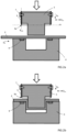
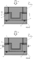
- FIG. 2a-d A more detailed view of the first mould part 3 and second mould part 4 in a cellulose product forming cycle is schematically illustrated in figures 2a-d .
- the first mould part 3 comprises a flexible cutting element 5 and the second mould part 4 comprises an anvil plate 6.
- the flexible cutting element 5 is arranged with a cutting edge 5a configured for operating in the pressing direction D P , as illustrated in for example figures 2a-d , and the anvil plate 6 is arranged to cooperate with the cutting edge 5a during forming of the cellulose products 1.
- the first mould part 3 and the second mould part 4 are pressed together in the pressing direction D P in a first pressing stroke S P1 to apply the forming pressure P F onto the cellulose blank structure 2.
- the flexible cutting element 5 is cutting out the cellulose product 1 from the cellulose blank structure 2 by pressing the cutting edge 5a towards and in contact with the anvil plate 6 with a predetermined cutting force F C , simultaneously with the first pressing stroke S P1 .
- the cutting edge 5a is pressed in contact with the anvil plate 6 with the predetermined cutting force F C simultaneously with applying the forming pressure P F onto the cellulose blank structure 2.
- the predetermined cutting force F C is in the range of 5-100 N/mm, preferably in the range of 10-50 N/mm, where the millimetres are referring to the cutting distance in the cellulose blank structure 2.
- the total cutting force is thus calculated by multiplying the total cutting distance in millimetres with the used cutting force per millimetre.
- the total cutting distance is equal with the total circumferential length of the cutting edge 5a of the flexible cutting element 5.
- the cellulose blank structure 2 is arranged between the first mould part 3 and the second mould part 4, as shown in figure 2a .
- the first mould part 3 is moved towards the second mould part 4, and in the illustrated embodiment, the cellulose blank structure 2 is pushed by the first mould part 3 into the second mould part 4, as shown in figure 2b .
- the forming pressure P F is established onto the cellulose blank structure 2 by the pushing force applied by the first mould part 3, as schematically illustrated in figure 2c .
- the interaction between the first mould part 3 and the second mould part 4 is thus establishing the forming pressure P F in the first pressing stroke S P1 .
- the dry-forming mould system S suitably comprises a heating unit that is establishing the forming temperature T F in the cellulose blank structure 2.
- the heating unit may have any suitable configuration, and as an example, a heated mould part or heated mould parts may be used for establishing the forming temperature T F .
- the heating unit may be integrated in or cast into the first mould part 3 and/or the second mould part 4, and suitable heating devices are e.g. electrical heaters, such as a resistor element, or fluid heaters. Other suitable heat sources may also be used.
- the flexible cutting element 5 is cutting out the cellulose product 1 from the cellulose blank structure 2 by pressing the cutting edge 5a towards and in contact with the anvil plate 6 with the predetermined cutting force F C .
- the cutting operation is taking place simultaneously with the first pressing stroke S P1 .
- the first mould part 3 and the second mould part 4 are released from each other after cutting out the cellulose product 1 for removing the cellulose product 1 from the dry-forming mould system S.
- the first mould part 3 is moved away from the second mould part 4 in a direction opposite the pressing direction D P , as shown in figure 2d , and the formed cellulose product 1 can be removed from the mould parts with a suitable removal device. After removal of the cellulose product 1, the cellulose product forming cycle can be repeated.
- the flexible cutting element 5 is releasably attached to the first mould part 3, and the flexible cutting element 5 extends along an outer peripheral edge section of the first mould part 3.
- the flexible cutting element 5 is extending around the first mould part 3, and the cutting edge 5a is provided with an extension and shape in a first plane P1 perpendicular to the pressing direction D P corresponding to an outer peripheral edge 1a of the cellulose product 1 to be formed in the dry-forming mould system S.
- the flexible cutting element 5 is arranged with a flat band-like or strip-like configuration formed from a sheet material, and has a thin elongated cross-sectional extension E CS in the pressing direction D P .
- the cross-sectional extension E CS is suitably arranged parallel to the pressing direction D P , as indicated with a dotted line in figure 2a and shown in figure 10a , or alternatively inclined.
- the flexible cutting element 5 is releasably attached to the first mould part 3.
- the flexible cutting element 5 is releasably attached to the first mould part 3 by means of one or more fastening elements 7.
- the flexible cutting element 5 is suitably arranged with grooves or openings 13 for receiving the fastening elements 7, as shown in figure 9b .
- the fastening elements 7 may be arranged as one or more screws that are holding the flexible cutting element 5 in position relative to the first mould part 3. The screws may engage threaded holes in the first mould part 3 for attaching the flexible cutting element 5 to the first mould part 3. It should however be understood that any suitable fastening means may be used in other embodiments, such as for example clamping members.
- the cutting element 5 can be easily removed from the first mould part 3. Once removed from the first mould part 3, a new or a sharpened cutting element 5 can be attached to the first mould part 3 and held in position by the fastening elements 7.
- the flexible cutting element 5 is made of a material that is allowed to flex or being deformed in order to adapt the shape of the flexible cutting element 5 to the shape of the outer peripheral edge 1a of the cellulose products 1 to be cut out from the cellulose blank structure 2, and also for adapting the cutting edge 5a to uneven sections or areas of the anvil plate 6 if necessary when the cutting edge 5a is in direct contact with the anvil plate 6.
- the flexible cutting element 5 is made from a material that is bendable without breaking when being shaped, such as for example a material with spring-like properties.
- the flexible cutting element 5 may for example be deformed or bent in the lateral direction D LA during a cutting operation, and after the cutting operation, the flexible cutting element is resuming its original non-deformed shape.
- the flexible cutting element 5 is suitably arranged as a steel rule die cutting element that is bent into the shape of the outer peripheral edge 1a of the cellulose products 1.
- Suitable materials for the flexible cutting element 5 are for example steel or other suitable metals or metallic materials.
- the anvil plate 6 may be made of a material that is withstanding the predetermined cutting force F C and minimizes blunting of the cutting edge 5a. Suitable materials for the anvil plate 6 are for example metals or metal alloys, such as steel compositions.
- the anvil plate 6 may comprise a material being softer than the cutting edge 5a. By using a softer material, the cutting edge 5a may be pressed at the predetermined cutting force F C in contact with the anvil plate 6 in an initial cutting step in which the cutting edge 5a is pressed against the anvil plate 6 for a first time. The initial cutting step is then used for deforming at least a part of the softer material of the anvil plate 6, such that the cutting edge 5a exerts an even cutting pressure onto the anvil plate 6.
- the deformation of the softer material of the anvil plate 6 is enabling an even cutting pressure distribution onto the anvil plate 6 from the cutting edge 5a in following pressing operations after the initial cutting step. It should be understood that the deformation of the softer material on the anvil plate 6 is maintained after the initial cutting step and is thus used for an efficient calibration of the exerted cutting pressure from the cutting edge 5a onto the anvil plate 6.
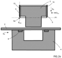
- FIG 2e an alternative configuration of the first mould part 3 with the flexible cutting element 5 is schematically illustrated.
- a glue layer 15 is used for releasably attaching the flexible cutting element 5 to the first mould part 3.
- the glue layer 15 is in this way efficiently bonding the flexible cutting element 5 to the first mould part 3 without the need for the fastening elements described above.
- the glue layer 15 is suitably formed as a layer of elastic or elastomeric material that is allowing the flexible cutting element 5 to deform during the pressing operation.
- the glue layer is further forming a seal between the flexible cutting element 5 and the first mould part 3 that is preventing fibres from the cellulose blank structure 2 from being stuck between the first mould part 3 and the flexible cutting element.
- the flexible cutting element 5 is suitably removed from the first mould part through mechanical or chemical removal of the glue layer.
- a glue layer may be used in any embodiment where the flexible cutting element is attached to the mould part.
- the flexible cutting element 5 is shown as an isolated part before being attached to the first mould part 3.
- the flexible cutting element 5 has a circular shaped configuration when viewed from below, as understood from figure 9a .
- the flexible cutting element 5 may have any suitable shape depending on the shape of the cellulose products 1 to be cut out from the cellulose blank structure.
- a side view of the flexible cutting element 5 is shown in figure 9b , which is corresponding to the position of the flexible cutting element 5 in figures 2a-e .
- the flexible cutting element 5 is suitably formed from a flexible metal blank 5a, as shown in figure 9c .
- the metal blank 5c has a thin thickness dimension allowing the metal blank 5c to be formed into the shape of the cellulose products 1 to be cut out from the cellulose blank structure 2. As shown in figure 9c , the metal blank 5c is bent into the desired shape of the flexible cutting element 5, as illustrated with dotted lines. Side edges 5d of the metal blank 5c are suitably joined by welding. Suitable metal blank materials are for example steel or other metals or metallic materials.
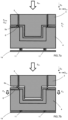
- the flexible cutting element 5 is configured for cutting out the cellulose product 1 from the cellulose blank structure 2 by pressing the cutting edge 5a towards and in contact with the anvil plate 6 with a predetermined cutting force F C , in a second pressing stroke S P2 in the pressing direction D P after start of the first pressing stroke S P1 .
- the dry-forming mould system S may further comprise a pressure member 9 that is pressing onto the flexible cutting element 5 in the pressing direction D P .
- the cutting edge 5a is pressed in contact with the anvil plate 6 with the predetermined cutting force F C in the second pressing stroke S P2 by use of the pressure member 9, and the pressure member 9 is thus used for establishing the cutting force F C for cutting out the cellulose products 1 from the cellulose blank structure 2.
- the pressure member 9 may be arranged as an electric, pneumatic or hydraulic actuator that is pressing the cutting edge 5a in contact with the anvil plate 6.
- the flexible cutting element 5 suitably is movably arranged in the pressing direction D P relative to the first mould part 3.
- the predetermined cutting force F C is established when pressing the cutting edge 5a towards and in contact with the anvil plate 6 upon movement of the flexible cutting element 5 relative to the first mould part 3.
- the flexible cutting element 5 is releasably attached to the first mould part 3 with suitable non-illustrated fastening elements.
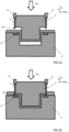
- the cellulose blank structure 2 has been arranged between the first mould part 3 and the second mould part 4, and the first mould part 3 is moved towards the second mould part 4.
- the cellulose blank structure 2 has been pushed by the first mould part 3 into the second mould part 4.
- the forming pressure P F is established onto the cellulose blank structure 2 by the pushing force applied by the first mould part 3 in a first pressing stroke S P1 , as schematically illustrated in figure 3b .
- the interaction between the first mould part 3 and the second mould part 4 is thus establishing the forming pressure P F and the forming temperature T F onto the air-formed cellulose blank structure 2 in the first pressing stroke S P1 .
- the cellulose blank structure 2 is heated to a forming temperature T F in the range of 100-300 °C, preferably in the range of 100-200 °C, and pressed with a forming pressure P F in the range of 1-100 MPa, preferably in the range of 4-20 MPa, in order to form the cellulose products 1.
- T F a forming temperature
- P F a forming pressure
- the flexible cutting element 5 is cutting out the cellulose product 1 from the cellulose blank structure 2 by pressing the cutting edge 5a towards and in contact with the anvil plate 6 with the predetermined cutting force F C .
- the cutting operation is taking place in the second pressing stroke S P2 after start of the first pressing stroke S P1 , by a movement of the flexible cutting element 5 in the pressing direction D P relative to the first mould part 3.
- the pressure member 9 may be used for both displacing the flexible cutting element 9 in the pressing direction D P from the position shown in figure 3b to the position shown in figure 3c , and for exerting the cutting force F C .
- the second pressing stroke S P2 is thus used for the cutting operation where the cutting edge 5a of the flexible cutting element 5 is pressed in contact with the anvil plate 6 for cutting out the cellulose products 1 from the cellulose blank structure 2.
- the first pressing stroke S P1 and the second pressing stroke S P2 may be overlapping in time as understood from figure 3c .
- FIG 3d an alternative configuration of the first mould part 3 with the flexible cutting element 5 is schematically illustrated.
- a sliding surface bearing 16 is arranged between the first mould part 3 and the flexible cutting element 5.
- the sliding surface bearing 16 is enabling low friction upon movement of the flexible cutting element 5 relative to the first mould part 3.
- the sliding surface bearing 16 may be made of an elastic or elastomeric material forming a seal that is preventing fibres from the cellulose blank structure 2 from being stuck between the first mould part 3 and the sliding surface bearing 16.
- Sliding surface bearings are suitably used in any embodiment where the flexible cutting element is arranged to move relative to the mould part.
- the second pressing stroke S P2 may take place when the first pressing stroke S P1 is completed or after the first pressing stroke S P1 is completed. In this way, the cutting operation with the pressing of the cutting edge 5a towards and in contact with the anvil plate 6 with the predetermined cutting force F C may take place upon movement of the first mould part 3 away from the second mould part 4.
- the movably arranged flexible cutting element 5 relative to the first mould part 3 is allowing pressing of the cutting edge 5a towards and in contact with the anvil plate 6 with the predetermined cutting force F C simultaneously with the first pressing stroke S P1 , and continue pressing the cutting edge 5a at the predetermined cutting force F C in contact with the anvil plate 6 when the first pressing stroke S P1 is completed.
- the first mould part 3 may be moved in a direction away from the second mould part 4 with a continued predetermined cutting force F C applied, where the cutting edge 5a is pressed towards and in contact with the anvil plate 6.
- the first mould part 3 is pushed towards the second mould part 4 with the cellulose blank structure 2 positioned between the mould parts, and the forming pressure P F is established onto the cellulose blank structure 2 by the pushing force applied by the first mould part 3 in a first pressing stroke S P1 .
- the flexible cutting element 5 is cutting out the cellulose product 1 from the cellulose blank structure 2 by pressing the cutting edge 5a towards and in contact with the anvil plate 6 with the predetermined cutting force F C .
- the cutting operation is taking place in a second pressing stroke S P2 after start of the first pressing stroke S P1 , by a movement of the flexible cutting element 5 in the pressing direction D P relative to the first mould part 3.
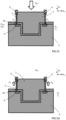
- the flexible cutting element 5 is releasably attached to the first mould part 3 via one or more spring elements 8.
- the flexible cutting element 5 is releasably attached to the one or more spring elements 8 with non-illustrated fastening members.
- the spring elements 8 are establishing the predetermined cutting force F C when pressing the cutting edge 5a in contact with the anvil plate 6.
- the spring characteristics are suitably chosen to exert the predetermined cutting force F C when the first mould part is pressed towards the second mould part in a forming position, as shown in figure 5c .
- the cutting edge 5a can be pressed in contact with the anvil plate 6 and the predetermined cutting force F C controlled by the one or more spring elements 8.
- the one or more spring elements 8 may be configured to control the predetermined cutting force F C , and further release the flexible cutting element 5 in a direction opposite the pressing direction D P when a predetermined release force F R acting on the one or more spring elements 8 is reached, as shown in figure 5d .
- the spring element may thus be arranged to release the pressure, when the predetermined release force F R is reached, and move the cutting edge 5a away from the anvil plate 6.
- the release function may for example be achieved by detaching or decoupling the flexible cutting element 5 from the spring elements 8 or by using bi-stable spring elements 8, when the predetermined release force F R acting on the one or more spring elements 10 is reached.
- the spring elements 8 may be arranged as metal springs or other suitable springs.
- the flexible cutting element 5 suitably is movably arranged in the pressing direction D P relative to the first mould part 3.
- the predetermined cutting force F C is established when pressing the cutting edge 5a towards and in contact with the anvil plate 6 upon movement of the flexible cutting element 5 relative to the first mould part 3.
- the forming pressure P F is established onto the cellulose blank structure 2 by the pushing force applied by the first mould part 3, and the flexible cutting element 5 is cutting out the cellulose product 1 from the cellulose blank structure 2 by pressing the cutting edge 5a towards and in contact with the anvil plate 6 with the predetermined cutting force F C through compression of the spring elements 8.
- the interaction between the first mould part 3 and the second mould part 4 is thus establishing the forming pressure P F and the forming temperature T F onto the air-formed cellulose blank structure 2.
- the cellulose blank structure 2 is heated to a forming temperature T F in the range of 100-300 °C, preferably in the range of 100-200 °C, and pressed with a forming pressure P F in the range of 1-100 MPa, preferably in the range of 4-20 MPa, in order to form the cellulose products 1.
- a forming temperature T F in the range of 100-300 °C, preferably in the range of 100-200 °C
- P F in the range of 1-100 MPa, preferably in the range of 4-20 MPa
- the second mould part 4 comprises a spring member 10 configured to support the anvil plate 6.
- the anvil plate 6 is through the arrangement with the spring member 10 movably arranged in the pressing direction D P relative to the second mould part 4.
- the spring member 10 is controlling the cutting force F C , and may also be used for releasing the anvil plate 6 in the pressing direction D P when a predetermined release force F R acting on the spring member 10 is reached, as illustrated in figure 6b .
- the flexible cutting element 5 may be movably arranged relative to the first mould part 3 or non-movably arranged, as described in the embodiments above.
- the second mould part 4 comprises a spring member 11 configured to support the second mould part 4.
- the second mould part 4 is through the arrangement with the spring member 11 movably arranged in the pressing direction D P relative to a base structure 14.
- the spring member 11 is controlling the cutting force F C , and may also be used for releasing the second mould part 4 in the pressing direction D P when a predetermined release force F R acting on the spring member 11 is reached, as illustrated in figure 7b .
- the spring function of the spring member 11 may be deactivated for a rigid connection between the second mould part 4 and the base structure 14 supporting the high forming pressure P F .
- the spring member is active.
- the flexible cutting element 5 is suitably movably arranged relative to the first mould part 3, as described in the embodiments above.
- the spring member 10 may be arranged with one or more spring elements made of metal, or one or more spring elements made of an elastomeric material, such as for example silicone or other suitable polymer.
- the release function may for example be achieved by detaching or decoupling the second mould part 4 from the spring member 11 or by using a bi-stable spring member 11, when the predetermined release force F R acting on the spring member 10 is reached.
- the flexible cutting element 5 comprises an edge portion 5b opposite the cutting edge 5a
- the first mould part 3 comprises a backing plate 3d with a deformable material structure 12 connected to the edge portion 5b.
- Suitable materials for the deformable material structure 12 are for example metals or metal alloys, such as steel compositions.
- the edge portion 5b is deforming the deformable material structure 12 when the cutting edge 5a is pressed at the predetermined cutting force F C in contact with the anvil plate 6 in the initial cutting step.
- the initial cutting step is thus used for deforming at least a part of the backing plate 3d, such that the cutting edge 5a exerts an even cutting pressure onto the anvil plate 6.
- the deformation of the deformable material structure 12 is enabling an even pressure distribution by the cutting edge 5a onto the anvil plate 6 in following pressing operations after the initial cutting step. It should be understood that the deformation of the deformable material structure 12 is maintained after the initial cutting step and is thus used for an efficient calibration of the exerted cutting pressure from the cutting edge 5a onto the anvil plate 6.
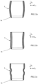
- the flexible cutting element 5 may be made of a single piece of material as shown in figures 10a and 11a-e , with one structural section in the lateral direction D LA , where the lateral direction D LA is perpendicular to the pressing direction D P .
- the flexible cutting element 5 is made of two or more structural sections 5s arranged in connection to each other in the lateral direction D LA in a layered configuration.
- the flexible cutting element 5 has a two-layer configuration and is made of two structural sections 5s arranged in connection to each other in the lateral direction D LA , where both structural sections 5s are forming the cutting edge 5a.
- the flexible cutting element 5 has a two-layer configuration and is made of two structural sections 5s arranged in connection to each other in the lateral direction D LA , where only one structural section 5s is forming the cutting edge 5a.
- the two or more structural sections 5s may be directly attached to each other for example through welding, gluing or other suitable attachment methods.
- the two or more structural sections 5s are arranged in connection to each other without being directly attached to each other.
- the flexible cutting element 5 has an even cross-sectional thickness with a wave-shaped cross-sectional configuration and the flexible cutting element 5 is formed with an outer undulating shape.
- the curved cross-sectional configurations in figures 11a-c are allowing the flexible cutting element 5 to flex and slightly deform during the pressing operation.
- the flexible cutting element 5 has a varied cross-sectional thickness and the flexible cutting element 5 is formed with an outer concave hourglass-like shape.
- the flexible cutting element 5 has a varied cross-sectional thickness and the flexible cutting element 5 is formed with an outer convex barrel-like shape. It should be understood that in other embodiments, the flexible cutting element 5 may be designed with any suitable shape and configuration and not only the ones described above and illustrated in the figures.
Landscapes
- Engineering & Computer Science (AREA)
- Life Sciences & Earth Sciences (AREA)
- Mechanical Engineering (AREA)
- Forests & Forestry (AREA)
- Manufacturing & Machinery (AREA)
- Wood Science & Technology (AREA)
- Chemical & Material Sciences (AREA)
- Composite Materials (AREA)
- Perforating, Stamping-Out Or Severing By Means Other Than Cutting (AREA)
- Moulds For Moulding Plastics Or The Like (AREA)
- Casting Or Compression Moulding Of Plastics Or The Like (AREA)
Description
- The present disclosure relates to a dry-forming mould system, where the dry-forming mould system is adapted for forming and cutting out a cellulose product from an air-formed cellulose blank structure. The dry-forming mould system comprises a first mould part and a second mould part arranged for cooperating with each other. The disclosure further relates to a method for manufacturing a cellulose product in a dry-forming mould system.
- Cellulose fibres are often used as raw material for producing or manufacturing products. Products formed of cellulose fibres can be used in many different situations where there is a need for having sustainable products. A wide range of products can be produced from cellulose fibres and a few examples are disposable plates and cups, cutlery, lids, bottle caps, coffee pods, hangers, and packaging materials.
- Forming moulds are commonly used when manufacturing cellulose products from raw materials including cellulose fibres, and traditionally the cellulose products have been produced with wet-forming techniques. A material commonly used for wet-forming cellulose fibre products is wet moulded pulp. Wet moulded pulp has the advantage of being considered as a sustainable packaging material, since it is produced from biomaterials and can be recycled after use. Consequently, wet moulded pulp has been quickly increasing in popularity for different applications. Wet moulded pulp articles are generally formed by immersing a suction forming mould into a liquid or semi liquid pulp suspension or slurry comprising cellulose fibres, and when suction is applied, a body of pulp is formed with the shape of the desired product by fibre deposition onto the forming mould. With all wet-forming techniques, there is a need for high amounts of water and then drying of the wet moulded product, where the drying is a very time and energy consuming part of the production and water is becoming a scarce resource. The demands on aesthetical, chemical and mechanical properties of cellulose products are increasing, and due to the properties of wet-formed cellulose products, the mechanical strength, flexibility, freedom in material thickness, and chemical properties are limited. It is also difficult in wet-forming processes to control the mechanical properties of the products with high precision. One development in the field of producing cellulose products is the forming of cellulose products from cellulose fibres without using wet-forming techniques. Instead, an air-formed cellulose blank structure is used for dry-forming the cellulose product in a dry-forming mould system. Through the dry-forming process, the cellulose product is formed into a dry moulded fibre (DMF) structure. The air-formed cellulose blank structure is inserted into a forming mould and during the forming of the cellulose products, the cellulose blank structure is subjected to a high forming pressure and a high forming temperature. When using this dry-forming process, an edge structure of the cellulose product needs to be formed, and commonly a cutting tool arranged as a part of the forming mould is used. When forming the cellulose products, the cutting tool will naturally blunt with regular use over time, and therefore the forming mould used has a limited life span. Changing the forming mould is a time consuming and costly operation.
- There is thus a need for an improved dry-forming mould system and method for manufacturing a cellulose product in a dry-forming mould system.
-
US2009/304960A1 discloses a method of forming a multilayer container in which a container body is formed by means of moulding from a multilayer structure including a plurality of laminated resin layers at least one of which is in a fused state, and simultaneously, a peripheral edge portion of the container body of the multilayer structure is cut with a predetermined width so as to form a flange portion. - An object of the present disclosure is to provide a dry-forming mould system and a method for dry-forming a cellulose product in a dry-forming mould system, where the previously mentioned problems are avoided. This object is at least partly achieved by the features of the independent claims. The dependent claims contain further developments of the dry-forming mould system and the method for dry-forming a cellulose product in a dry-forming mould system.
- The disclosure concerns a dry-forming mould system for dry-forming a cellulose product from an air-formed cellulose blank structure. The dry-forming mould system comprises a first mould part and an opposing second mould part configured for cooperating with each other in a pressing direction upon forming of the cellulose product. The first mould part and the second mould part are configured for being pressed together in the pressing direction in a first pressing stroke to apply a forming pressure onto the cellulose blank structure. A flexible cutting element with a cutting edge configured for operating in the pressing direction is releasably attached to the first mould part, and the second mould part comprises an anvil plate arranged to cooperate with the cutting edge of the flexible cutting element. The flexible cutting element is configured for cutting out the cellulose product from the cellulose blank structure by pressing the cutting edge towards and in contact with the anvil plate with a predetermined cutting force, simultaneously with the first pressing stroke or in a second pressing stroke in the pressing direction after start of the first pressing stroke.
- Advantages with these features are that the system is providing a releasably attached flexible cutting element for efficient cutting operations, where cellulose products are cut out from the cellulose blank structure. The flexible cutting element can be removed from the first mould part and exchanged for a new or sharpened flexible cutting element. The solution is increasing the life span of the mould parts, and is enabling a fast and low-cost exchange of cutting elements. The flexible cutting element is made of a material that is allowed to flex in order to adapt the shape of the flexible cutting element to a desired shape. The flexible cutting element is made from a material that is bendable without breaking when being shaped. With such a configuration, the flexible cutting element can be bent into the desired shape of the outer peripheral edge of the cellulose products. Suitable materials for the flexible cutting element are for example steel or other suitable metals or metallic materials.
- In one embodiment, the cutting edge has an extension and shape in a first plane perpendicular to the pressing direction corresponding to an outer peripheral edge of the cellulose product.
- In one embodiment, the flexible cutting element has a configuration with one structural section in a lateral direction, or two or more structural sections arranged in connection to each other in a lateral direction, where the lateral direction is perpendicular to the pressing direction. By using one, two or more structural sections, the characteristics of the flexible cutting element can be efficiently designed, such as for example bending strength or material stiffness.
- In one embodiment, the flexible cutting element is movably arranged in the pressing direction relative to the first mould part. By the movable arrangement of the flexible cutting element, the second pressing stroke is enabled for an efficient cutting operation of the cellulose products from the cellulose blank structure.
- In one embodiment, the flexible cutting element extends along an outer peripheral edge section of the first mould part. With this configuration, a simple deign of the system is achieved, where the flexible cutting element is easily attached to and removed from the first mould part.
- In one embodiment, the flexible cutting element is arranged in a groove of the first mould part. The groove has an extension in the pressing direction and comprises a groove opening facing the second mould part. The groove is providing an alternative solution for efficient cutting operations.
- In one embodiment, the flexible cutting element is releasably attached to the first mould part by means of one or more fastening elements. The fastening elements may be arranged as one or more screws that are holding the flexible cutting element in position relative to the first mould part. The screws may engage threaded holes in the first mould part for attaching the flexible cutting element to the first mould part. However, any suitable fastening elements may be used, such as for example clamping members. By removing the fastening elements, the cutting element can be easily removed from the first mould part. Once removed from the first mould part, a new or a sharpened cutting element can be attached to the first mould part and held in position by the fastening elements.
- In one embodiment, the flexible cutting element is releasably attached to the first mould part via one or more spring elements. The spring elements are used for efficiently controlling the predetermined cutting force. By choosing suitable spring characteristics, the predetermined cutting force can be adapted to the specific dry-forming mould system.
- In one embodiment, the anvil plate comprises a material being softer than the cutting edge. By using a softer material, the cutting edge may be pressed at the predetermined cutting force in contact with the anvil plate in an initial cutting step in which the cutting edge is pressed against the anvil plate for a first time. The initial cutting step is used for deforming at least a part of the softer material of the anvil plate, such that the cutting edge exerts an even cutting pressure onto the anvil plate. The deformation of the softer material of the anvil plate is enabling an even cutting pressure distribution from the cutting edge onto the anvil plate in following pressing operations after the initial cutting step for an efficient cutting operation with high precision.
- In one embodiment, the second mould part comprises a spring member configured to support the anvil plate. The spring member is controlling the cutting force, and the spring member may be used for releasing the anvil plate in the pressing direction when a predetermined release force acting on the spring member is reached. The spring member is efficiently controlling the predetermined cutting force. By choosing suitable spring characteristics, the predetermined cutting force can be adapted to the specific dry-forming mould system. Through the releasing function, the cutting operation can be terminated when the predetermined release force acting on the spring member is reached.
- In one embodiment, the second mould part comprises a spring member configured to support the second mould part. The spring member is controlling the cutting force, and the spring member may be used for releasing the second mould part in the pressing direction when a predetermined release force acting on the spring member is reached. The spring member is efficiently controlling the predetermined cutting force. By choosing suitable spring characteristics, the predetermined cutting force can be adapted to the specific dry-forming mould system. Through the releasing function, the cutting operation can be terminated when the predetermined release force acting on the spring member is reached.
- In one embodiment, the flexible cutting element comprises an edge portion opposite the cutting edge, wherein the first mould part comprises a backing plate with a deformable material structure connected to the edge portion. The deformable material structure is used for an even pressure distribution between the cutting edge and the anvil plate. When the cutting edge is pressed at the predetermined cutting force in contact with the anvil plate in an initial cutting step in which the cutting edge is pressed against the anvil plate for a first time, at least a part of the backing plate is deformed by pressure from the edge portion upon pressing of the cutting edge in contact with the anvil plate, such that the cutting edge exerts an even cutting pressure onto the anvil plate. By using a deformable material, the edge portion is deforming the deformable material structure when the cutting edge is pressed at the predetermined cutting force in contact with the anvil plate in the initial cutting step. The initial cutting step is thus used for deforming at least a part of the backing plate, such that the cutting edge exerts an even cutting pressure onto the anvil plate. The deformation of the deformable material structure is enabling an even pressure distribution by the cutting edge onto the anvil plate in following pressing operations after the initial cutting step.
- The disclosure further concerns a method for dry-forming a cellulose product in a dry-forming mould system from an air-formed cellulose blank structure. The dry-forming mould system comprises a first mould part and an opposing second mould part arranged to cooperate with each other in a pressing direction upon forming of the cellulose product. A flexible cutting element with a cutting edge operating in the pressing direction is releasably attached to the first mould part, and the second mould part comprises an anvil plate arranged to cooperate with the cutting edge of the flexible cutting element. The method comprises the steps: providing the air-formed cellulose blank structure, and arranging the cellulose blank structure between the first mould part and the second mould part; forming the cellulose product by pressing together the first mould part and the second mould part in a first pressing stroke in the pressing direction, wherein a forming pressure is applied onto the cellulose blank structure; cutting out the cellulose product from the cellulose blank structure by pressing the cutting edge towards and in contact with the anvil plate with a predetermined cutting force; wherein the cutting edge is pressed towards and in contact with the anvil plate simultaneously with the first pressing stroke, or wherein the cutting edge is pressed towards and in contact with the anvil plate in a second pressing stroke in the pressing direction after start of the first pressing stroke.
- Advantages with these features are that the method is providing an efficient cutting operation when cutting out the cellulose products from the cellulose blank structure. The flexible cutting element is releasably attached to the first mould part for efficient cutting operations, and the flexible cutting element can be easily removed from the first mould part and exchanged for a new or sharpened flexible cutting element. The solution is increasing the life span of the mould parts, and is enabling a fast and low-cost exchange of cutting elements. The flexible cutting element is made of a material that is allowed to flex in order to adapt the shape of the flexible cutting element to the shape of an outer peripheral edge of the cellulose products to be cut out from the cellulose blank structure.
- In one embodiment, the forming pressure is in the range of 1-100 MPa, preferably in the range of 4-20 MPa, and the predetermined cutting force is in the range of 5-100 N/mm, preferably in the range of 10-50 N/mm. These parameters are providing efficient forming and cutting operations when producing cellulose products in the dry-forming mould system.
- In one embodiment, the flexible cutting element is releasably attached to the first mould part via one or more spring elements. The method further comprises the step: establishing the predetermined cutting force by the one or more spring elements when pressing the cutting edge in contact with the anvil plate. The spring elements are efficiently controlling the predetermined cutting force. By choosing suitable spring characteristics, the predetermined cutting force can be adapted to the specific dry-forming mould system.
- In one embodiment, the method further comprises the step: pressing the cutting edge in contact with the anvil plate and controlling the predetermined cutting force by the one or more spring elements.
- In one embodiment, the flexible cutting element is releasably attached to the one or more spring elements, wherein the one or more spring elements are configured to control the predetermined cutting force. The method further comprises the step: releasing the flexible cutting element in a direction opposite the pressing direction when a predetermined release force acting on the one or more spring elements is reached. Through the releasing function, the cutting operation can be terminated when the predetermined release force acting on the one or more spring elements is reached.
- In one embodiment, the flexible cutting element is movably arranged in the pressing direction relative to the first mould part. The method further comprises the step: establishing the predetermined cutting force when pressing the cutting edge towards and in contact with the anvil plate upon movement of the flexible cutting element relative to the first mould part. By the movable arrangement of the flexible cutting element, the second pressing stroke is enabled for an efficient cutting operation of the cellulose products from the cellulose blank structure.
- In one embodiment, the method further comprises the steps: pressing the cutting edge towards and in contact with the anvil plate with the predetermined cutting force simultaneously with the first pressing stroke, and continue pressing the cutting edge at the predetermined cutting force in contact with the anvil plate when the first pressing stroke is completed. With this configuration, the first mould part may be separated from the second mould part with a continued predetermined cutting force applied, where the cutting edge is pressed towards and in contact with the anvil plate.
- In one embodiment, the method further comprises the step: pressing the cutting edge in contact with the anvil plate with the predetermined cutting force simultaneously with applying the forming pressure onto the cellulose blank structure. This method step is enabling fast and efficient simultaneous product forming and cutting operations.
- In one embodiment, the method further comprises the steps: pressing the cutting edge in contact with the anvil plate with the predetermined cutting force in the second pressing stroke by use of a pressure member pressing onto the flexible cutting element in the pressing direction, when or after the first pressing stroke is completed. The pressure member is establishing the cutting force for cutting out the cellulose products from the cellulose blank structure. The pressure member may be arranged as an electric, pneumatic or hydraulic actuator that is pressing the cutting edge in contact with the anvil plate.
- In one embodiment, the anvil plate comprises a material being softer than the cutting edge. The method further comprises the steps: pressing the cutting edge at the predetermined cutting force in contact with the anvil plate in an initial cutting step in which the cutting edge is pressed against the anvil plate for a first time, wherein at least a part of the softer material of the anvil plate is deformed such that the cutting edge exerts an even cutting pressure onto the anvil plate. By using a softer material, the cutting edge may be pressed at the predetermined cutting force in contact with the anvil plate in the initial cutting step, and the initial cutting step is used for deforming at least a part of the softer material of the anvil plate, such that the cutting edge exerts an even cutting pressure onto the anvil plate. The deformation of the softer material of the anvil plate is enabling an even cutting pressure from the cutting edge onto the anvil plate in following pressing operations after the initial cutting step.
- In one embodiment, the second mould part comprises a spring member configured to support the anvil plate. The method further comprises the step: releasing the anvil plate in the pressing direction when a predetermined release force acting on the spring member is reached. The spring member is efficiently controlling the predetermined cutting force, and the predetermined cutting force can be adapted to the specific dry-forming mould system by choosing suitable spring characteristics. The releasing function is enabling termination of the cutting operation when the predetermined release force acting on the spring member is reached.
- In one embodiment, the second mould part comprises a spring member configured to support the second mould part. The method further comprises the step: releasing the second mould part in the pressing direction when a predetermined release force acting on the spring member is reached. The spring member is efficiently controlling the predetermined cutting force, and the predetermined cutting force can be adapted to the specific dry-forming mould system by choosing suitable spring characteristics. The releasing function is enabling termination of the cutting operation when the predetermined release force acting on the spring member is reached.
- In one embodiment, the method further comprises the step: releasing the first mould part and the second mould part from to each other after cutting out the cellulose product for removing the cellulose product from the dry-forming mould system. The releasing of the mould parts is enabling efficient removal of the formed cellulose products from the dry-forming mould system.
- In one embodiment, the flexible cutting element comprises an edge portion opposite the cutting edge, and the first mould part comprises a backing plate with a deformable material structure connected to the edge portion. The method comprises the steps: pressing the cutting edge at the predetermined cutting force in contact with the anvil plate in an initial cutting step in which the cutting edge is pressed against the anvil plate for a first time, wherein at least a part of the backing plate is deformed by pressure from the edge portion upon pressing of the cutting edge in contact with the anvil plate such that the cutting edge exerts an even cutting pressure onto the anvil plate. When the cutting edge is pressed at the predetermined cutting force in contact with the anvil plate in the initial cutting step, at least a part of the backing plate is deformed by pressure from the edge portion upon pressing of the cutting edge in contact with the anvil plate, such that the cutting edge exerts an even cutting pressure onto the anvil plate. By using a deformable material, the edge portion is deforming the deformable material structure when the cutting edge is pressed at the predetermined cutting force in contact with the anvil plate in the initial cutting step. The initial cutting step is thus used for deforming at least a part of the backing plate, such that the cutting edge exerts an even cutting pressure onto the anvil plate. The deformation of the deformable material structure is enabling an even pressure distribution by the cutting edge onto the anvil plate in following pressing operations after the initial cutting step.
- The disclosure will be described in detail in the following, with reference to the attached drawings, in which
- Fig. 1a-c
- show schematically, in side views, a dry-forming mould system with mould parts according to an embodiment,
- Fig. 2a-e
- show schematically, in cross-sectional side views, interacting mould parts and flexible cutting element according to embodiments,
- Fig. 3a-d
- show schematically, in cross-sectional side views, interacting mould parts and flexible cutting element according to alternative embodiments,
- Fig. 4a-b
- show schematically, in cross-sectional side views, interacting mould parts and flexible cutting element according to an alternative embodiment,
- Fig. 5a-d
- show schematically, in cross-sectional side views, interacting mould parts and flexible cutting element according to an alternative embodiment,
- Fig. 6a-b
- show schematically, in cross-sectional side views, interacting mould parts and flexible cutting element according to an alternative embodiment,
- Fig. 7a-b
- show schematically, in cross-sectional side views, interacting mould parts and flexible cutting element according to an alternative embodiment,
- Fig. 8
- shows schematically, in a cross-sectional side view, interacting mould parts and flexible cutting element according to an alternative embodiment,
- Fig. 9a-c
- show schematically, in a view from below, in a side view, and in a perspective view, the flexible cutting element according to an embodiment,
- Fig. 10a-c
- show schematically, in cross-sectional side views, the flexible cutting element according to alternative embodiments, and
- Fig. 11a-e
- show schematically, in cross-sectional side views, the flexible cutting element according to alternative embodiments.
- Various aspects of the disclosure will hereinafter be described in conjunction with the appended drawings to illustrate and not to limit the disclosure, wherein like designations denote like elements, and variations of the described aspects are not restricted to the specifically shown embodiments, but are applicable on other variations of the disclosure.
-
Figures 1a-c schematically show a dry-forming mould system S for dry-formingcellulose products 1 from an air-formed celluloseblank structure 2 into a dry moulded fibre (DMF) structure. The dry-forming mould system S comprises afirst mould part 3 and an opposingsecond mould part 4 configured for interacting and cooperating with each other in a pressing direction DP of the dry-forming mould system S for forming thecellulose products 1 from the air-formed celluloseblank structure 2. Thefirst mould part 3 and/or thesecond mould part 4 are movably arranged relative to each other in the pressing direction DP. A direction perpendicular to the pressing direction is defined as a lateral direction DLA of the dry-forming mould system S, as shown infigures 1a-c . - With an air-formed cellulose
blank structure 2 is meant an essentially air-formed fibrous web structure produced from cellulose fibres. The cellulose fibres may originate from a suitable cellulose raw material, such as a pulp material. Suitable pulp materials are for example fluff pulp, paper structures, or other cellulose fibre containing structures. The cellulose fibres may also be extracted from agricultural waste materials, for example wheat straws, fruit and vegetable peels, bagasse, etc. With air-forming of the celluloseblank structure 2 is meant the formation of a cellulose blank structure in a dry forming process in which the cellulose fibres are air-formed to produce the celluloseblank structure 2. When forming the celluloseblank structure 2 in the air-forming process, the cellulose fibres are carried and formed to the fibreblank structure 2 by air as carrying medium. This is different from a normal papermaking process or a traditional wet-forming process, where water is used as carrying medium for the cellulose fibres when forming the paper or fibre structure. In the air-forming process, small amounts of water or other substances may if desired be added to the cellulose fibres in order to change the properties of the cellulose products, but air is still used as carrying medium in the forming process. The celluloseblank structure 2 may, if suitable have a dryness that is mainly corresponding to the ambient humidity in the atmosphere surrounding the air-formed celluloseblank structure 2. As an alternative, the dryness of the celluloseblank structure 2 can be controlled in order to have a suitable dryness level when forming thecellulose products 1. - The air-formed cellulose
blank structure 2 may be formed of cellulose fibres in a conventional air-forming process or in a cellulose blank air-forming module. For example, the celluloseblank structure 2 may have a composition where the fibres are of the same origin or alternatively contain a mix of two or more types of cellulose fibres, depending on the desired properties of thecellulose products 1. The cellulose fibres used in the celluloseblank structure 2 are during the forming process of thecellulose products 1 strongly bonded to each other with hydrogen bonds, due to applied forming pressure and forming temperature together with adequate moist content in the celluloseblank structure 2. The cellulose fibres may be mixed with other substances or compounds to a certain amount as will be further described below. With cellulose fibres is meant any type of cellulose fibres, such as natural cellulose fibres or manufactured cellulose fibres. The celluloseblank structure 2 may specifically comprise at least 95% cellulose fibres, or more specifically at least 99% cellulose fibres. - The air-formed cellulose
blank structure 2 may have a single-layer or a multi-layer configuration. A celluloseblank structure 2 having a single-layer configuration is referring to a structure that is formed of one layer containing cellulose fibres. A celluloseblank structure 2 having a multi-layer configuration is referring to a structure that is formed of two or more layers comprising cellulose fibres, where the layers may have the same or different compositions or configurations. - The cellulose
blank structure 2 may comprise one or more additional cellulose layers comprising cellulose fibres, where an additional cellulose layer for example is arranged as a carrying layer for one or more other layers of the celluloseblank structure 2. The one or more additional cellulose layers may act as reinforcement layers having a higher tensile strength than other layers of the celluloseblank structure 2. This is useful when one or more air-formed layers of the celluloseblank structure 2 have compositions with low tensile strength in order to avoid that the celluloseblank structure 2 will break during the forming of thecellulose products 1. The one or more additional cellulose layers with higher tensile strength act in this way as a supporting structure for other layers of the celluloseblank structure 2. The one or more additional cellulose layers may be of a different composition than the rest of the celluloseblank structure 2, such as for example a tissue layer containing cellulose fibres, an airlaid structure comprising cellulose fibres, or other suitable layer structures. It is thus not necessary that the one or more additional cellulose layers are air-formed. Other suitable additional layers may also be used such as for example silicone coated structures or bio-based films. - The one or more air-formed layers of the cellulose
blank structure 2 are fluffy and airy structures, where the cellulose fibres forming the structures are arranged relatively loosely in relation to each other. The fluffy celluloseblank structures 2 are used for an efficient dry-forming of thecellulose products 1, allowing the cellulose fibres to form thecellulose products 1 in an efficient way during the dry-forming process in the dry-forming mould system S. - To form the
cellulose products 1 from the celluloseblank structure 2 in the dry-forming mould system S, the celluloseblank structure 2 is first provided from a suitable source. The celluloseblank structure 2 may be air-formed from cellulose fibres and arranged on rolls or in stacks. The rolls or stacks may thereafter be arranged in connection to the dry-forming mould system S. As an alternative, the celluloseblank structure 2 may be air-formed from cellulose fibres in a cellulose blank air-forming module arranged in connection to the dry-forming mould system S, and directly fed to the dry-forming mould system S after the air-forming operation. The celluloseblank structure 2 is fed to the dry-forming mould system S with suitable non-illustrated transportation means, such as forming wires, vacuum belt feeders, or conveyor belts. - The dry-forming mould system S comprises one or more oppositely arranged pairs of
first mould parts 3 andsecond mould parts 4, and the mould parts are configured for dry-forming thecellulose products 1 from the celluloseblank structure 2. The dry-forming mould system S may be arranged with only one pair offirst mould part 3 and opposingsecond mould part 4 in a single-cavity configuration, or alternatively with two or more pairs of first mould parts and opposing second mould parts in a multi-cavity configuration. A single-cavity configuration dry-forming mould system thus comprises only one forming mould structure with afirst mould part 3 and a cooperatingsecond mould part 4. A multi-cavity configuration dry-forming mould system comprises two or more forming mould structures, each having cooperatingfirst mould parts 3 andsecond mould parts 4. - In the embodiment illustrated in
figures 1a-c , the dry-forming mould system S is arranged as a single-cavity configuration dry-forming mould system S comprising one forming mould structure with afirst mould part 3 and asecond mould part 4 movably arranged relative to each other. In the following, the dry-forming mould system S will be described in connection to a single-cavity configuration dry-forming mould system, but the disclosure is equally applicable on a multi-cavity configuration dry-forming mould system. - The dry-forming mould system S may for example be constructed so that the
first mould part 3 or thesecond mould part 4 is movable and arranged to move towards the other mould part during the dry-forming process, where the other mould part is stationary or non-movably arranged. In the embodiment illustrated infigures 1a-c , thefirst mould part 3 is movably arranged and thesecond mould part 4 is stationary. In an alternative non-illustrated embodiment, both thefirst mould part 3 and thesecond mould part 4 are movably arranged, where thefirst mould part 3 and thesecond mould part 4 are displaced in directions towards each other during the dry-forming process. The moving mould parts may be displaced with a suitable actuator, such as a hydraulic, pneumatic, or electric actuator. A combination of different actuators may also be used. The relative speed between thefirst mould part 3 and thesecond mould part 4 during the dry-forming process is suitably chosen so that the celluloseblank structure 2 is evenly distributed in a forming cavity between the mould parts during the dry-forming process. - As indicated in
figure 1a , thefirst mould part 3 is movably arranged in relation to thesecond mould part 4 in the pressing direction DP and thefirst mould part 3 is further arranged to be pressed towards thesecond mould part 4 in the pressing direction DP during dry-forming of thecellulose products 1 for establishing a forming pressure PF onto the celluloseblank structure 2. When dry-forming thecellulose products 1, the celluloseblank structure 2 is transported in a feeding direction DF and arranged between thefirst mould part 3 and thesecond mould part 4 when the mould parts are in an open state, as shown infigure 1a . Suitably, the celluloseblank structure 2 is fed intermittently to the mould parts. When the celluloseblank structure 2 has been arranged between thefirst mould part 3 and thesecond mould part 4, thefirst mould part 3 is moved towards thesecond mould part 4 during the dry-forming process. When the forming pressure PF together with a suitable forming temperature TF are established by the mould parts onto the celluloseblank structure 2, the movement of thefirst mould part 3 is stopped in a product forming position FPOS, as shown infigure 1b . Thefirst mould part 3 is thereafter moved in a direction opposite the pressing direction DP away from thesecond mould part 4 after a certain time duration or directly after thefirst mould part 3 has been stopped, as shown infigure 1c . A suitable control system may be used for controlling the operation of the dry-forming mould system S and the mould parts. - The
cellulose products 1 are dry-formed from the celluloseblank structure 2 in the dry-forming mould system S by applying the forming pressure PF and a forming temperature TF onto the air-formed celluloseblank structure 2. The celluloseblank structure 2 is heated to a forming temperature TF in the range of 100-300 °C, preferably in the range of 100-200 °C, and pressed with a forming pressure PF in the range of 1-100 MPa, preferably in the range of 4-20 MPa. Thefirst mould part 3 is arranged for forming thecellulose products 1 through interaction with the correspondingsecond mould part 4. During dry-forming of thecellulose products 1, the celluloseblank structure 2 is arranged between thefirst mould part 3 and thesecond mould part 4, and exerted to the forming pressure PF in the range of 1-100 MPa, preferably in the range of 4-20 MPa, and the forming temperature TF in the range of 100-300°C, preferably in the range of 100-200 °C. When dry-forming thecellulose products 1, hydrogen bonds are formed between the cellulose fibres in the celluloseblank structure 2 arranged between thefirst mould part 3 and thesecond mould part 4, due to the applied forming pressure PF and forming temperature TF together with adequate moist content in the celluloseblank structure 2. The temperature and pressure levels are for example measured in the celluloseblank structure 2 during the dry-forming process with suitable sensors arranged in or in connection to the cellulose fibres in the celluloseblank structure 2. The celluloseblank structure 2 is typically containing less than 45 weight percent water when formed in the dry-forming mould system S. - The cellulose
blank structure 2 may be arranged between the mould parts in any suitable way, and as an example, the celluloseblank structure 2 may be fed with a suitable feeding device, which is transporting the celluloseblank structure 2 to the mould parts in the feeding direction DF. The feeding device could for example be a conveyor belt, a forming wire unit, an industrial robot, or any other suitable manufacturing equipment. The transportation speed may differ depending on the types ofcellulose products 1 produced, and is chosen to match the forming speed in the dry-forming mould system S. - In the embodiment illustrated in
figures 1a-c , thefirst mould part 3 is arranged as a positive mould part, and thesecond mould part 4 is arranged as a negative mould part. In alternative embodiments, thefirst mould part 3 may be arranged as a negative mould part, and thesecond mould part 4 arranged as a positive mould part. - The
first mould part 3 and/or thesecond mould part 4 may be arranged with a deformation element. During the forming of thecellulose products 1, the deformation element is deformed to exert the forming pressure PF onto the celluloseblank structure 2, and through deformation of the deformation element, an even pressure distribution is achieved even if the cellulose products are having complex three-dimensional shapes, such as for example shapes with a recessed undercut section having a negative draft angle, or if the celluloseblank structure 2 is having a varied thickness. To exert a required forming pressure PF on the celluloseblank structure 2, the deformation element is made of a material that can be deformed when a force or pressure is applied, and the deformation element is suitably made of an elastic material capable of recovering size and shape after deformation. The deformation element may further be made of a material with suitable properties that is withstanding the high forming pressure PF and forming temperature TF levels used when forming thecellulose products 1. The deformation element may be made of a suitable structure of elastomeric material or materials, and as an example, the deformation element may be made of a massive structure or an essentially massive structure of silicone rubber, polyurethane, polychloroprene, or rubber. A single deformation element structure, or a plurality of deformation element structures, may be used. - Depending on the design of the dry-forming mould system S, the forming pressure PF may be applied onto the air-formed cellulose
blank structure 2 in the range of 1-100 MPa, preferably in the range of 4-20 MPa, in a single pressing operation OSP. With a single pressing operation OSP is meant that thecellulose product 1 is formed from the celluloseblank structure 2 in one single pressing step in the dry-forming mould system S. In the single pressing operation OSP, thefirst mould part 3 and thesecond mould part 4 are interacting with each other for establishing the forming pressure PF and the forming temperature TF during a single operational engagement step. Thus, in the single pressing operation OSP, the forming pressure PF and the forming temperature TF are not applied to the cellulose blank structure in two or more repeated pressing steps. - A more detailed view of the
first mould part 3 andsecond mould part 4 in a cellulose product forming cycle is schematically illustrated infigures 2a-d . In the illustrated embodiment, thefirst mould part 3 comprises aflexible cutting element 5 and thesecond mould part 4 comprises ananvil plate 6. Theflexible cutting element 5 is arranged with acutting edge 5a configured for operating in the pressing direction DP, as illustrated in for examplefigures 2a-d , and theanvil plate 6 is arranged to cooperate with thecutting edge 5a during forming of thecellulose products 1. Thefirst mould part 3 and thesecond mould part 4 are pressed together in the pressing direction DP in a first pressing stroke SP1 to apply the forming pressure PF onto the celluloseblank structure 2. Theflexible cutting element 5 is cutting out thecellulose product 1 from the celluloseblank structure 2 by pressing thecutting edge 5a towards and in contact with theanvil plate 6 with a predetermined cutting force FC, simultaneously with the first pressing stroke SP1. In this embodiment, thecutting edge 5a is pressed in contact with theanvil plate 6 with the predetermined cutting force FC simultaneously with applying the forming pressure PF onto the celluloseblank structure 2. - To cut out the
cellulose products 1 from the celluloseblank structure 2 in an efficient manner, the predetermined cutting force FC is in the range of 5-100 N/mm, preferably in the range of 10-50 N/mm, where the millimetres are referring to the cutting distance in the celluloseblank structure 2. The total cutting force is thus calculated by multiplying the total cutting distance in millimetres with the used cutting force per millimetre. The total cutting distance is equal with the total circumferential length of thecutting edge 5a of theflexible cutting element 5. These ranges are suitable for all dry-forming mould system S embodiments. - In order to form the
cellulose products 1, the celluloseblank structure 2 is arranged between thefirst mould part 3 and thesecond mould part 4, as shown infigure 2a . Upon forming of thecellulose products 1, thefirst mould part 3 is moved towards thesecond mould part 4, and in the illustrated embodiment, the celluloseblank structure 2 is pushed by thefirst mould part 3 into thesecond mould part 4, as shown infigure 2b . When thefirst mould part 3 is pushed towards thesecond mould part 4 with the celluloseblank structure 2 positioned between the mould parts, the forming pressure PF is established onto the celluloseblank structure 2 by the pushing force applied by thefirst mould part 3, as schematically illustrated infigure 2c . The interaction between thefirst mould part 3 and thesecond mould part 4 is thus establishing the forming pressure PF in the first pressing stroke SP1. The dry-forming mould system S suitably comprises a heating unit that is establishing the forming temperature TF in the celluloseblank structure 2. The heating unit may have any suitable configuration, and as an example, a heated mould part or heated mould parts may be used for establishing the forming temperature TF. The heating unit may be integrated in or cast into thefirst mould part 3 and/or thesecond mould part 4, and suitable heating devices are e.g. electrical heaters, such as a resistor element, or fluid heaters. Other suitable heat sources may also be used. In the position shown infigure 2c , theflexible cutting element 5 is cutting out thecellulose product 1 from the celluloseblank structure 2 by pressing thecutting edge 5a towards and in contact with theanvil plate 6 with the predetermined cutting force FC. The cutting operation is taking place simultaneously with the first pressing stroke SP1. When the cellulose products have been formed, thefirst mould part 3 and thesecond mould part 4 are released from each other after cutting out thecellulose product 1 for removing thecellulose product 1 from the dry-forming mould system S. - When the cellulose products have been dry-formed in the dry-forming mould system S, the
first mould part 3 is moved away from thesecond mould part 4 in a direction opposite the pressing direction DP, as shown infigure 2d , and the formedcellulose product 1 can be removed from the mould parts with a suitable removal device. After removal of thecellulose product 1, the cellulose product forming cycle can be repeated. - As shown in
figures 2a-d , theflexible cutting element 5 is releasably attached to thefirst mould part 3, and theflexible cutting element 5 extends along an outer peripheral edge section of thefirst mould part 3. In this way theflexible cutting element 5 is extending around thefirst mould part 3, and thecutting edge 5a is provided with an extension and shape in a first plane P1 perpendicular to the pressing direction DP corresponding to an outerperipheral edge 1a of thecellulose product 1 to be formed in the dry-forming mould system S. Further, theflexible cutting element 5 is arranged with a flat band-like or strip-like configuration formed from a sheet material, and has a thin elongated cross-sectional extension ECS in the pressing direction DP. The cross-sectional extension ECS is suitably arranged parallel to the pressing direction DP, as indicated with a dotted line infigure 2a and shown infigure 10a , or alternatively inclined. - For all embodiments, the
flexible cutting element 5 is releasably attached to thefirst mould part 3. In the embodiment shown infigures 2a-d , theflexible cutting element 5 is releasably attached to thefirst mould part 3 by means of one ormore fastening elements 7. Theflexible cutting element 5 is suitably arranged with grooves oropenings 13 for receiving thefastening elements 7, as shown infigure 9b . Thefastening elements 7 may be arranged as one or more screws that are holding theflexible cutting element 5 in position relative to thefirst mould part 3. The screws may engage threaded holes in thefirst mould part 3 for attaching theflexible cutting element 5 to thefirst mould part 3. It should however be understood that any suitable fastening means may be used in other embodiments, such as for example clamping members. By removing thefastening elements 7, the cuttingelement 5 can be easily removed from thefirst mould part 3. Once removed from thefirst mould part 3, a new or a sharpenedcutting element 5 can be attached to thefirst mould part 3 and held in position by thefastening elements 7. - With the expression flexible is for all embodiments meant that the
flexible cutting element 5 is made of a material that is allowed to flex or being deformed in order to adapt the shape of theflexible cutting element 5 to the shape of the outerperipheral edge 1a of thecellulose products 1 to be cut out from the celluloseblank structure 2, and also for adapting thecutting edge 5a to uneven sections or areas of theanvil plate 6 if necessary when thecutting edge 5a is in direct contact with theanvil plate 6. Theflexible cutting element 5 is made from a material that is bendable without breaking when being shaped, such as for example a material with spring-like properties. Theflexible cutting element 5 may for example be deformed or bent in the lateral direction DLA during a cutting operation, and after the cutting operation, the flexible cutting element is resuming its original non-deformed shape. Theflexible cutting element 5 is suitably arranged as a steel rule die cutting element that is bent into the shape of the outerperipheral edge 1a of thecellulose products 1. Suitable materials for theflexible cutting element 5 are for example steel or other suitable metals or metallic materials. - The
anvil plate 6 may be made of a material that is withstanding the predetermined cutting force FC and minimizes blunting of thecutting edge 5a. Suitable materials for theanvil plate 6 are for example metals or metal alloys, such as steel compositions. Theanvil plate 6 may comprise a material being softer than thecutting edge 5a. By using a softer material, thecutting edge 5a may be pressed at the predetermined cutting force FC in contact with theanvil plate 6 in an initial cutting step in which thecutting edge 5a is pressed against theanvil plate 6 for a first time. The initial cutting step is then used for deforming at least a part of the softer material of theanvil plate 6, such that thecutting edge 5a exerts an even cutting pressure onto theanvil plate 6. The deformation of the softer material of theanvil plate 6 is enabling an even cutting pressure distribution onto theanvil plate 6 from thecutting edge 5a in following pressing operations after the initial cutting step. It should be understood that the deformation of the softer material on theanvil plate 6 is maintained after the initial cutting step and is thus used for an efficient calibration of the exerted cutting pressure from thecutting edge 5a onto theanvil plate 6. - In
figure 2e , an alternative configuration of thefirst mould part 3 with theflexible cutting element 5 is schematically illustrated. In this embodiment, aglue layer 15 is used for releasably attaching theflexible cutting element 5 to thefirst mould part 3. Theglue layer 15 is in this way efficiently bonding theflexible cutting element 5 to thefirst mould part 3 without the need for the fastening elements described above. Theglue layer 15 is suitably formed as a layer of elastic or elastomeric material that is allowing theflexible cutting element 5 to deform during the pressing operation. The glue layer is further forming a seal between theflexible cutting element 5 and thefirst mould part 3 that is preventing fibres from the celluloseblank structure 2 from being stuck between thefirst mould part 3 and the flexible cutting element. When needed, theflexible cutting element 5 is suitably removed from the first mould part through mechanical or chemical removal of the glue layer. A glue layer may be used in any embodiment where the flexible cutting element is attached to the mould part. - In
figures 9a-b , theflexible cutting element 5 is shown as an isolated part before being attached to thefirst mould part 3. In the illustrated embodiment, theflexible cutting element 5 has a circular shaped configuration when viewed from below, as understood fromfigure 9a . However, theflexible cutting element 5 may have any suitable shape depending on the shape of thecellulose products 1 to be cut out from the cellulose blank structure. A side view of theflexible cutting element 5 is shown infigure 9b , which is corresponding to the position of theflexible cutting element 5 infigures 2a-e . Theflexible cutting element 5 is suitably formed from a flexible metal blank 5a, as shown infigure 9c . Themetal blank 5c has a thin thickness dimension allowing themetal blank 5c to be formed into the shape of thecellulose products 1 to be cut out from the celluloseblank structure 2. As shown infigure 9c , themetal blank 5c is bent into the desired shape of theflexible cutting element 5, as illustrated with dotted lines. Side edges 5d of themetal blank 5c are suitably joined by welding. Suitable metal blank materials are for example steel or other metals or metallic materials. - In an alternative embodiment illustrated in
figures 3a-c , theflexible cutting element 5 is configured for cutting out thecellulose product 1 from the celluloseblank structure 2 by pressing thecutting edge 5a towards and in contact with theanvil plate 6 with a predetermined cutting force FC, in a second pressing stroke SP2 in the pressing direction DP after start of the first pressing stroke SP1. The dry-forming mould system S may further comprise apressure member 9 that is pressing onto theflexible cutting element 5 in the pressing direction DP. Thecutting edge 5a is pressed in contact with theanvil plate 6 with the predetermined cutting force FC in the second pressing stroke SP2 by use of thepressure member 9, and thepressure member 9 is thus used for establishing the cutting force FC for cutting out thecellulose products 1 from the celluloseblank structure 2. Thepressure member 9 may be arranged as an electric, pneumatic or hydraulic actuator that is pressing thecutting edge 5a in contact with theanvil plate 6. - With the configuration illustrated in
figures 3a-c , theflexible cutting element 5 suitably is movably arranged in the pressing direction DP relative to thefirst mould part 3. The predetermined cutting force FC is established when pressing thecutting edge 5a towards and in contact with theanvil plate 6 upon movement of theflexible cutting element 5 relative to thefirst mould part 3. Theflexible cutting element 5 is releasably attached to thefirst mould part 3 with suitable non-illustrated fastening elements. - In
figure 3a , the celluloseblank structure 2 has been arranged between thefirst mould part 3 and thesecond mould part 4, and thefirst mould part 3 is moved towards thesecond mould part 4. The celluloseblank structure 2 has been pushed by thefirst mould part 3 into thesecond mould part 4. When thefirst mould part 3 is pushed towards thesecond mould part 4 with the celluloseblank structure 2 positioned between the mould parts, the forming pressure PF is established onto the celluloseblank structure 2 by the pushing force applied by thefirst mould part 3 in a first pressing stroke SP1, as schematically illustrated infigure 3b . The interaction between thefirst mould part 3 and thesecond mould part 4 is thus establishing the forming pressure PF and the forming temperature TF onto the air-formed celluloseblank structure 2 in the first pressing stroke SP1. The celluloseblank structure 2 is heated to a forming temperature TF in the range of 100-300 °C, preferably in the range of 100-200 °C, and pressed with a forming pressure PF in the range of 1-100 MPa, preferably in the range of 4-20 MPa, in order to form thecellulose products 1. In the position shown infigure 3c , theflexible cutting element 5 is cutting out thecellulose product 1 from the celluloseblank structure 2 by pressing thecutting edge 5a towards and in contact with theanvil plate 6 with the predetermined cutting force FC. The cutting operation is taking place in the second pressing stroke SP2 after start of the first pressing stroke SP1, by a movement of theflexible cutting element 5 in the pressing direction DP relative to thefirst mould part 3. Thepressure member 9 may be used for both displacing theflexible cutting element 9 in the pressing direction DP from the position shown infigure 3b to the position shown infigure 3c , and for exerting the cutting force FC. The second pressing stroke SP2 is thus used for the cutting operation where thecutting edge 5a of theflexible cutting element 5 is pressed in contact with theanvil plate 6 for cutting out thecellulose products 1 from the celluloseblank structure 2. The first pressing stroke SP1 and the second pressing stroke SP2 may be overlapping in time as understood fromfigure 3c . When the respective pressing operations are completed, thefirst mould part 3 is moved in a direction away from thesecond mould part 4, and theflexible cutting element 5 is moved back to the position shown infigure 3a . - In
figure 3d , an alternative configuration of thefirst mould part 3 with theflexible cutting element 5 is schematically illustrated. In this embodiment, a sliding surface bearing 16 is arranged between thefirst mould part 3 and theflexible cutting element 5. The sliding surface bearing 16 is enabling low friction upon movement of theflexible cutting element 5 relative to thefirst mould part 3. The sliding surface bearing 16 may be made of an elastic or elastomeric material forming a seal that is preventing fibres from the celluloseblank structure 2 from being stuck between thefirst mould part 3 and the sliding surface bearing 16. Sliding surface bearings are suitably used in any embodiment where the flexible cutting element is arranged to move relative to the mould part. - In alternative embodiments, the second pressing stroke SP2 may take place when the first pressing stroke SP1 is completed or after the first pressing stroke SP1 is completed. In this way, the cutting operation with the pressing of the
cutting edge 5a towards and in contact with theanvil plate 6 with the predetermined cutting force FC may take place upon movement of thefirst mould part 3 away from thesecond mould part 4. - In further alternative embodiments, the movably arranged
flexible cutting element 5 relative to thefirst mould part 3 is allowing pressing of thecutting edge 5a towards and in contact with theanvil plate 6 with the predetermined cutting force FC simultaneously with the first pressing stroke SP1, and continue pressing thecutting edge 5a at the predetermined cutting force FC in contact with theanvil plate 6 when the first pressing stroke SP1 is completed. In this way, thefirst mould part 3 may be moved in a direction away from thesecond mould part 4 with a continued predetermined cutting force FC applied, where thecutting edge 5a is pressed towards and in contact with theanvil plate 6. - In an alternative embodiment shown in
figures 4a-b , theflexible cutting element 5 is releasably attached to thefirst mould part 3 and arranged in agroove 3b of thefirst mould part 3. Thegroove 3b has an extension in the pressing direction DP and comprises a groove opening 3c facing thesecond mould part 4. Theflexible cutting element 5 may be movably arranged within thegroove 3b relative to thefirst mould part 3, as shown infigures 4a-b , with a configuration and operation similar to the embodiment described above in connection tofigures 3a-c . Infigure 4a , thefirst mould part 3 is pushed towards thesecond mould part 4 with the celluloseblank structure 2 positioned between the mould parts, and the forming pressure PF is established onto the celluloseblank structure 2 by the pushing force applied by thefirst mould part 3 in a first pressing stroke SP1. Infigure 4b , theflexible cutting element 5 is cutting out thecellulose product 1 from the celluloseblank structure 2 by pressing thecutting edge 5a towards and in contact with theanvil plate 6 with the predetermined cutting force FC. The cutting operation is taking place in a second pressing stroke SP2 after start of the first pressing stroke SP1, by a movement of theflexible cutting element 5 in the pressing direction DP relative to thefirst mould part 3. Thecutting edge 5a is pressed in contact with theanvil plate 6 with the predetermined cutting force FC in the second pressing stroke SP2 by use of thepressure member 9, and thepressure member 9 is thus used for displacing theflexible cutting element 9 in the pressing direction and for establishing the cutting force FC for cutting out thecellulose products 1 from the celluloseblank structure 2. - In an alternative embodiment illustrated in
figures 5a-d , theflexible cutting element 5 is releasably attached to thefirst mould part 3 via one ormore spring elements 8. Theflexible cutting element 5 is releasably attached to the one ormore spring elements 8 with non-illustrated fastening members. Thespring elements 8 are establishing the predetermined cutting force FC when pressing thecutting edge 5a in contact with theanvil plate 6. The spring characteristics are suitably chosen to exert the predetermined cutting force FC when the first mould part is pressed towards the second mould part in a forming position, as shown infigure 5c . Thecutting edge 5a can be pressed in contact with theanvil plate 6 and the predetermined cutting force FC controlled by the one ormore spring elements 8. In this embodiment, the one ormore spring elements 8 may be configured to control the predetermined cutting force FC, and further release theflexible cutting element 5 in a direction opposite the pressing direction DP when a predetermined release force FR acting on the one ormore spring elements 8 is reached, as shown infigure 5d . The spring element may thus be arranged to release the pressure, when the predetermined release force FR is reached, and move thecutting edge 5a away from theanvil plate 6. The release function may for example be achieved by detaching or decoupling theflexible cutting element 5 from thespring elements 8 or by usingbi-stable spring elements 8, when the predetermined release force FR acting on the one ormore spring elements 10 is reached. Thespring elements 8 may be arranged as metal springs or other suitable springs. - With the configuration illustrated in
figures 5a-d , theflexible cutting element 5 suitably is movably arranged in the pressing direction DP relative to thefirst mould part 3. The predetermined cutting force FC is established when pressing thecutting edge 5a towards and in contact with theanvil plate 6 upon movement of theflexible cutting element 5 relative to thefirst mould part 3. - In
figure 5a , the celluloseblank structure 2 has been arranged between thefirst mould part 3 and thesecond mould part 4, and thefirst mould part 3 is moved towards thesecond mould part 4. The celluloseblank structure 2 has been pushed by thefirst mould part 3 into thesecond mould part 4. When thefirst mould part 3 is pushed towards thesecond mould part 4 with the celluloseblank structure 2 positioned between the mould parts, the forming pressure PF is built up between the mould parts onto the celluloseblank structure 2 by the pushing force applied by thefirst mould part 3, as schematically illustrated infigure 5b . Upon further movement of thefirst mould part 3 towards thesecond mould part 4, as shown infigure 5c , the forming pressure PF is established onto the celluloseblank structure 2 by the pushing force applied by thefirst mould part 3, and theflexible cutting element 5 is cutting out thecellulose product 1 from the celluloseblank structure 2 by pressing thecutting edge 5a towards and in contact with theanvil plate 6 with the predetermined cutting force FC through compression of thespring elements 8. The interaction between thefirst mould part 3 and thesecond mould part 4 is thus establishing the forming pressure PF and the forming temperature TF onto the air-formed celluloseblank structure 2. The celluloseblank structure 2 is heated to a forming temperature TF in the range of 100-300 °C, preferably in the range of 100-200 °C, and pressed with a forming pressure PF in the range of 1-100 MPa, preferably in the range of 4-20 MPa, in order to form thecellulose products 1. When the predetermined release force FR is reached, theflexible cutting element 5 is moved in a direction away from the second mould part, as shown infigure 5d , and thecutting edge 5a is moved away from theanvil plate 6. Once the pressing operations are completed, thefirst mould part 3 is moved in a direction away from thesecond mould part 4, and theflexible cutting element 5 is moved back to the position shown infigure 5a . - In an alternative embodiment shown in
figures 6a-b , thesecond mould part 4 comprises aspring member 10 configured to support theanvil plate 6. Theanvil plate 6 is through the arrangement with thespring member 10 movably arranged in the pressing direction DP relative to thesecond mould part 4. Thespring member 10 is controlling the cutting force FC, and may also be used for releasing theanvil plate 6 in the pressing direction DP when a predetermined release force FR acting on thespring member 10 is reached, as illustrated infigure 6b . In this embodiment, theflexible cutting element 5 may be movably arranged relative to thefirst mould part 3 or non-movably arranged, as described in the embodiments above. Thespring member 10 may be arranged with one or more spring elements made of metal, or one or more spring elements made of an elastomeric material, such as for example silicone or other suitable polymer. The release function may for example be achieved by detaching or decoupling theanvil plate 6 from thespring member 10 or by using abi-stable spring member 10, when the predetermined release force FR acting on thespring member 10 is reached. - In a further alternative embodiment shown in
figures 7a-b , thesecond mould part 4 comprises aspring member 11 configured to support thesecond mould part 4. Thesecond mould part 4 is through the arrangement with thespring member 11 movably arranged in the pressing direction DP relative to abase structure 14. Thespring member 11 is controlling the cutting force FC, and may also be used for releasing thesecond mould part 4 in the pressing direction DP when a predetermined release force FR acting on thespring member 11 is reached, as illustrated infigure 7b . During the forming of thecellulose product 1, the spring function of thespring member 11 may be deactivated for a rigid connection between thesecond mould part 4 and thebase structure 14 supporting the high forming pressure PF. During the cutting operation, the spring member is active. In this embodiment, theflexible cutting element 5 is suitably movably arranged relative to thefirst mould part 3, as described in the embodiments above. Thespring member 10 may be arranged with one or more spring elements made of metal, or one or more spring elements made of an elastomeric material, such as for example silicone or other suitable polymer. The release function may for example be achieved by detaching or decoupling thesecond mould part 4 from thespring member 11 or by using abi-stable spring member 11, when the predetermined release force FR acting on thespring member 10 is reached. - In an alternative embodiment shown in
figure 8 , theflexible cutting element 5 comprises anedge portion 5b opposite thecutting edge 5a, and thefirst mould part 3 comprises abacking plate 3d with adeformable material structure 12 connected to theedge portion 5b. When thecutting edge 5a is pressed at the predetermined cutting force FC in contact with theanvil plate 6 in an initial cutting step in which thecutting edge 5a is pressed against theanvil plate 6 for a first time, at least a part of thebacking plate 3d is deformed by pressure from theedge portion 5b upon pressing of thecutting edge 5a in contact with theanvil plate 6 such that thecutting edge 5a exerts an even cutting pressure onto theanvil plate 6. - Suitable materials for the
deformable material structure 12 are for example metals or metal alloys, such as steel compositions. By using a deformable material, theedge portion 5b is deforming thedeformable material structure 12 when thecutting edge 5a is pressed at the predetermined cutting force FC in contact with theanvil plate 6 in the initial cutting step. The initial cutting step is thus used for deforming at least a part of thebacking plate 3d, such that thecutting edge 5a exerts an even cutting pressure onto theanvil plate 6. The deformation of thedeformable material structure 12 is enabling an even pressure distribution by thecutting edge 5a onto theanvil plate 6 in following pressing operations after the initial cutting step. It should be understood that the deformation of thedeformable material structure 12 is maintained after the initial cutting step and is thus used for an efficient calibration of the exerted cutting pressure from thecutting edge 5a onto theanvil plate 6. - For all embodiments, the
flexible cutting element 5 may be made of a single piece of material as shown infigures 10a and11a-e , with one structural section in the lateral direction DLA, where the lateral direction DLA is perpendicular to the pressing direction DP. In alternative embodiments, theflexible cutting element 5 is made of two or morestructural sections 5s arranged in connection to each other in the lateral direction DLA in a layered configuration. In the embodiment shown infigure 10b , theflexible cutting element 5 has a two-layer configuration and is made of twostructural sections 5s arranged in connection to each other in the lateral direction DLA, where bothstructural sections 5s are forming thecutting edge 5a. In the embodiment shown infigure 10c , theflexible cutting element 5 has a two-layer configuration and is made of twostructural sections 5s arranged in connection to each other in the lateral direction DLA, where only onestructural section 5s is forming thecutting edge 5a. The two or morestructural sections 5s may be directly attached to each other for example through welding, gluing or other suitable attachment methods. Alternatively, the two or morestructural sections 5s are arranged in connection to each other without being directly attached to each other. - The
flexible cutting element 5 may as illustrated infigure 10a have a straight cross-sectional configuration, where theflexible cutting element 5 is arranged with a flat band-like or strip-like configuration and has a thin elongated cross-sectional extension in the pressing direction DP. In other alternative embodiments, theflexible cutting element 5 may instead have a shaped cross-sectional configuration. Infigure 11a , theflexible cutting element 5 has an even cross-sectional thickness with a curved cross-sectional configuration and theflexible cutting element 5 is formed with an outer convex barrel-like shape. Infigure 11b , theflexible cutting element 5 has an even cross-sectional thickness with a curved cross-sectional configuration and theflexible cutting element 5 is formed with an outer concave hourglass-like shape. Infigure 11c , theflexible cutting element 5 has an even cross-sectional thickness with a wave-shaped cross-sectional configuration and theflexible cutting element 5 is formed with an outer undulating shape. The curved cross-sectional configurations infigures 11a-c are allowing theflexible cutting element 5 to flex and slightly deform during the pressing operation. Infigure 11d , theflexible cutting element 5 has a varied cross-sectional thickness and theflexible cutting element 5 is formed with an outer concave hourglass-like shape. Infigure 11e , theflexible cutting element 5 has a varied cross-sectional thickness and theflexible cutting element 5 is formed with an outer convex barrel-like shape. It should be understood that in other embodiments, theflexible cutting element 5 may be designed with any suitable shape and configuration and not only the ones described above and illustrated in the figures. - It will be appreciated that the above description is merely exemplary in nature and is not intended to limit the present disclosure, its application or uses, wherein the scope of protection is defined by the appended claims. While specific examples have been described in the specification and illustrated in the drawings, it will be understood by those of ordinary skill in the art that various changes may be made without departing from the scope defined by the claims. Furthermore, modifications may be made to adapt a particular situation or material to the teachings of the present disclosure.
- Therefore, it is intended that the present disclosure not be limited to the particular examples illustrated by the drawings and described in the specification as the best mode presently contemplated for carrying out the teachings of the present disclosure, but that the scope of the present disclosure will include any embodiments falling within the foregoing description and the appended claims. Reference signs mentioned in the claims should not be seen as limiting the extent of the matter protected by the claims, and their sole function is to make claims easier to understand.
-
- 1:
- Cellulose product
- 1a:
- Outer peripheral edge
- 2:
- Cellulose blank structure
- 3:
- First mould part
- 3b:
- Groove
- 3c:
- Groove opening
- 3d:
- Backing plate
- 4:
- Second mould part
- 5:
- Flexible cutting element
- 5a:
- Cutting edge
- 5b:
- Edge portion
- 5c:
- Metal blank
- 5d:
- Side edge
- 5s:
- Structural section
- 6:
- Anvil plate
- 7:
- Fastening element
- 8:
- Spring element
- 9:
- Pressure member
- 10:
- Spring member
- 11:
- Spring member
- 12:
- Deformable material structure
- 13:
- Opening
- 14:
- Base structure
- 15:
- Glue layer
- 16:
- Sliding surface bearing
- DF:
- Feeding direction
- DLA:
- Lateral direction
- DP:
- Pressing direction
- ECS:
- Cross-sectional extension
- FC:
- Cutting force
- FPOS:
- Product forming position
- FR:
- Release force
- OSP:
- Single pressing operation
- S:
- Dry-forming mould system
- SP1:
- First pressing stroke
- SP2:
- Second pressing stroke
- P1:
- First plane
- PF:
- Forming pressure
- TF:
- Forming temperature
Claims (15)
- A dry-forming cellulose product mould system (S) for dry-forming a cellulose product (1) from an air-formed cellulose blank structure (2), wherein the dry-forming mould system (S) comprises:an air-formed cellulose blank structure (2) and a cellulose product (1) manufactured therefrom; anda first mould part (3) and an opposing second mould part (4) configured for cooperating with each other in a pressing direction (DP) upon forming of the cellulose product (1), wherein the first mould part (3) and the second mould part (4) are configured for being pressed together in the pressing direction (DP) in a first pressing stroke (SP1) to apply a forming pressure (PF) onto the cellulose blank structure (2),wherein a flexible cutting element (5) with a cutting edge (5a) configured for operating in the pressing direction (DP) is releasably attached to the first mould part (3), wherein the second mould part (4) comprises an anvil plate (6) arranged to cooperate with the cutting edge (5a) of the flexible cutting element (5), wherein the flexible cutting element (5) is made of a material that is allowed to flex in order to adapt the shape of the flexible cutting element (5) to a desired shape, and that is bendable without breaking when being shaped, wherein the flexible cutting element (5) is configured for cutting out the cellulose product (1) from the cellulose blank structure (2) by pressing the cutting edge (5a) towards and in contact with the anvil plate (6) with a predetermined cutting force (FC), simultaneously with the first pressing stroke (SP1) or in a second pressing stroke (SP2) in the pressing direction (DP) after start of the first pressing stroke (SP1).
- The dry-forming mould system (S) according to claim 1,
wherein the cutting edge (5a) has an extension and shape in a first plane (P1) perpendicular to the pressing direction (DP) corresponding to an outer peripheral edge (1a) of the cellulose product (1). - The dry-forming mould system (S) according to claim 1 or 2,
wherein the flexible cutting element (5) has a configuration with one structural section in a lateral direction (DLA), or two or more structural sections (5s) arranged in connection to each other in a lateral direction (DLA), wherein the lateral direction (DLA) is perpendicular to the pressing direction (DP). - The dry-forming mould system (S) according to any preceding claim,
wherein the flexible cutting element (5) is movably arranged in the pressing direction (DP) relative to the first mould part (3). - The dry-forming mould system (S) according to any preceding claim,
wherein the flexible cutting element (5) extends along an outer peripheral edge section of the first mould part (3). - The dry-forming mould system (S) according to any of claims 1 to 4,
wherein the flexible cutting element (5) is arranged in a groove (3b) of the first mould part (3), wherein the groove (3b) has an extension in the pressing direction (DP) and comprises a groove opening (3c) facing the second mould part (4). - The dry-forming mould system (S) according to any preceding claim,
wherein the flexible cutting element (5) is releasably attached to the first mould part (3) by means of one or more fastening elements (7). - The dry-forming mould system (S) according to any preceding claim,
wherein the flexible cutting element (5) is releasably attached to the first mould part (3) via one or more spring elements (8). - The dry-forming mould system (S) according to any preceding claim,
wherein the anvil plate (6) comprises a material being softer than the cutting edge (5a). - The dry-forming mould system (S) according to any preceding claim,
wherein the second mould part (4) comprises a spring member (10) configured to support the anvil plate (6), wherein the anvil plate (6) is movably arranged in the pressing direction (DP) relative to the second mould part (4). - The dry-forming mould system (S) according to any preceding claim,
wherein the second mould part (4) comprises a spring member (11) configured to support the second mould part (4), wherein the second mould part (4) is movably arranged in the pressing direction (DP). - The dry-forming mould system (S) according to any preceding claim,
wherein the flexible cutting element (5) comprises an edge portion (5b) opposite the cutting edge (5a), wherein the first mould part (3) comprises a backing plate (3d) with a deformable material structure (12) connected to the edge portion (5b). - A method for dry-forming a cellulose product (1) in a dry-forming mould system (S) from an air-formed cellulose blank structure (2), wherein the dry-forming mould system (S) comprises a first mould part (3) and an opposing second mould part (4) arranged to cooperate with each other in a pressing direction (DP) upon forming of the cellulose product (1), wherein a flexible cutting element (5) with a cutting edge (5a) operating in the pressing direction (DP) is releasably attached to the first mould part (3), wherein the second mould part (4) comprises an anvil plate (6) arranged to cooperate with the cutting edge (5a) of the flexible cutting element (5), wherein the flexible cutting element (5) is made of a material that is allowed to flex in order to adapt the shape of the flexible cutting element (5) to a desired shape, and that is bendable without breaking when being shaped, wherein the method comprises the steps:providing the air-formed cellulose blank structure (2), and arranging the cellulose blank structure (2) between the first mould part (3) and the second mould part (4);forming the cellulose product (1) by pressing together the first mould part (3) and the second mould part (4) in a first pressing stroke (SP1) in the pressing direction (DP), wherein a forming pressure (PF) is applied onto the cellulose blank structure (2);cutting out the cellulose product (1) from the cellulose blank structure (2) by pressing the cutting edge (5a) towards and in contact with the anvil plate (6) with a predetermined cutting force (FC); wherein the cutting edge (5a) is pressed towards and in contact with the anvil plate (6) simultaneously with the first pressing stroke (SP1), or wherein the cutting edge (5a) is pressed towards and in contact with the anvil plate (6) in a second pressing stroke (SP2) in the pressing direction (DP) after start of the first pressing stroke (SP1).
- The method according to claim 13,wherein the forming pressure (PF) is in the range of 1-100 MPa, preferably in the range of 4-20 MPa, andwherein the predetermined cutting force (FC) is in the range of 5-100 N/mm, preferably in the range of 10-50 N/mm.
- The method according to claim 13 or 14,
wherein the flexible cutting element (5) is releasably attached to the first mould part (3) via one or more spring elements (8), wherein the method further comprises the step: establishing the predetermined cutting force (FC) by the one or more spring elements (8) when pressing the cutting edge (5a) in contact with the anvil plate (6).
Applications Claiming Priority (2)
| Application Number | Priority Date | Filing Date | Title |
|---|---|---|---|
| SE2250445A SE547296C2 (en) | 2022-04-08 | 2022-04-08 | A dry-forming mould system and a method for manufacturing a cellulose product in a dry-forming mould system |
| PCT/EP2023/055995 WO2023194032A1 (en) | 2022-04-08 | 2023-03-09 | A dry-forming mould system and a method for manufacturing a cellulose product in a dry-forming mould system |
Publications (2)
| Publication Number | Publication Date |
|---|---|
| EP4504469A1 EP4504469A1 (en) | 2025-02-12 |
| EP4504469B1 true EP4504469B1 (en) | 2025-06-18 |
Family
ID=85601679
Family Applications (1)
| Application Number | Title | Priority Date | Filing Date |
|---|---|---|---|
| EP23710851.9A Active EP4504469B1 (en) | 2022-04-08 | 2023-03-09 | A dry-forming mould system and a method for manufacturing a cellulose product in a dry-forming mould system |
Country Status (8)
| Country | Link |
|---|---|
| EP (1) | EP4504469B1 (en) |
| DK (1) | DK4504469T3 (en) |
| ES (1) | ES3040418T3 (en) |
| FI (1) | FI4504469T3 (en) |
| PL (1) | PL4504469T3 (en) |
| SE (1) | SE547296C2 (en) |
| TW (1) | TW202404771A (en) |
| WO (1) | WO2023194032A1 (en) |
Families Citing this family (7)
| Publication number | Priority date | Publication date | Assignee | Title |
|---|---|---|---|---|
| AU2020385893A1 (en) * | 2019-11-19 | 2022-06-23 | Varden Process Pty Ltd | A tool for use in a thermoforming process |
| SE547761C2 (en) * | 2023-12-22 | 2025-11-25 | Pulpac AB | Multi-cavity forming mould system and method for dry-forming cellulose products in a multi-cavity forming mould system |
| SE547760C2 (en) * | 2023-12-22 | 2025-11-25 | Pulpac AB | Multi-cavity forming mould system and method for dry-forming cellulose products in a multi-cavity forming mould system |
| EP4585410A3 (en) * | 2024-01-12 | 2025-07-23 | Illig Maschinenbau GmbH | Device for producing packaging blanks |
| CN118544444B (en) * | 2024-05-06 | 2024-11-05 | 浙江江山朗众新材料科技有限公司 | Compression molding leftover material collecting device and collecting method thereof |
| DE102024117149A1 (en) * | 2024-06-18 | 2025-12-18 | Kiefel Gmbh | Three-dimensional shaped body and method for producing a three-dimensional shaped body from fiber-containing material |
| EP4678363A1 (en) | 2024-07-10 | 2026-01-14 | Yangi AB | Method and apparatus for dry manufacturing rigid cellulose products |
Family Cites Families (10)
| Publication number | Priority date | Publication date | Assignee | Title |
|---|---|---|---|---|
| US5393474A (en) * | 1993-08-19 | 1995-02-28 | Davidson Textron Inc. | Method for molding a shaped plastic trim panel |
| DE19601422A1 (en) * | 1996-01-17 | 1997-07-24 | Tetra Laval Holdings & Finance | Thermo-forming equipment for plastic sheet or strip, used in production of packaging for fluids |
| JP2004051159A (en) * | 2002-07-19 | 2004-02-19 | Idemitsu Unitech Co Ltd | Container manufacturing method and container printing apparatus |
| JP4503220B2 (en) * | 2002-07-25 | 2010-07-14 | 東洋製罐株式会社 | Multilayer cutting method and multilayer molded article |
| CN1915643B (en) * | 2005-08-15 | 2010-09-15 | 小岛冲压工业株式会社 | Forming Machine |
| WO2010013531A1 (en) * | 2008-07-30 | 2010-02-04 | 株式会社高橋型精 | Blanking die |
| JP5571806B2 (en) * | 2012-05-22 | 2014-08-13 | ヤマセイ株式会社 | Mold for carbon fiber reinforced plastic parts and method for producing carbon fiber reinforced plastic parts |
| CN210453727U (en) * | 2019-07-12 | 2020-05-05 | 广东源鑫精密模具科技有限公司 | Thermal forming die with novel punching structure |
| SE546658C2 (en) * | 2020-08-26 | 2025-01-07 | Pulpac AB | A multi-cavity forming mould system and a method for forming cellulose products in a multi-cavity forming mould system |
| DE102021101358A1 (en) * | 2021-01-22 | 2022-07-28 | Marbach Werkzeugbau Gmbh | Technique for forming three-dimensional articles |
-
2022
- 2022-04-08 SE SE2250445A patent/SE547296C2/en unknown
-
2023
- 2023-03-09 WO PCT/EP2023/055995 patent/WO2023194032A1/en not_active Ceased
- 2023-03-09 FI FIEP23710851.9T patent/FI4504469T3/en active
- 2023-03-09 EP EP23710851.9A patent/EP4504469B1/en active Active
- 2023-03-09 DK DK23710851.9T patent/DK4504469T3/en active
- 2023-03-09 PL PL23710851.9T patent/PL4504469T3/en unknown
- 2023-03-09 ES ES23710851T patent/ES3040418T3/en active Active
- 2023-03-20 TW TW112110249A patent/TW202404771A/en unknown
Also Published As
| Publication number | Publication date |
|---|---|
| FI4504469T3 (en) | 2025-09-12 |
| TW202404771A (en) | 2024-02-01 |
| WO2023194032A1 (en) | 2023-10-12 |
| ES3040418T3 (en) | 2025-10-30 |
| PL4504469T3 (en) | 2025-10-13 |
| DK4504469T3 (en) | 2025-09-08 |
| SE2250445A1 (en) | 2023-10-09 |
| SE547296C2 (en) | 2025-06-24 |
| EP4504469A1 (en) | 2025-02-12 |
Similar Documents
| Publication | Publication Date | Title |
|---|---|---|
| EP4504469A1 (en) | A dry-forming mould system and a method for manufacturing a cellulose product in a dry-forming mould system | |
| JP7739437B2 (en) | Method for forming a cellulose product in a mold system from a cellulose blank structure, mold system, and cellulose blank structure | |
| EP3969659B1 (en) | A method for producing cellulose products and a rotary forming mould system | |
| EP4448266B1 (en) | A pressing module for forming cellulose products and a method for forming cellulose products | |
| US20260008248A1 (en) | Forming mould comprising a movable element and method for forming cellulose products | |
| US20250369194A1 (en) | Ejection element, forming mould comprising an ejection element and method for forming cellulose products | |
| EP4021702A1 (en) | A method for producing cellulose products and a rotary forming mould system | |
| SE545309C2 (en) | Forming mould system and method for forming three-dimensional cellulose products | |
| EP4204199A1 (en) | A multi-cavity forming mould system and a method for forming cellulose products in a multi-cavity forming mould system | |
| EP4504470B1 (en) | A method for forming a cellulose product in a dry-forming mould system | |
| US20250369193A1 (en) | Deformation element, forming mould comprising a deformation element and method for forming cellulose products | |
| SE2250875A1 (en) | Method for transporting a cellulose blank structure via a buffering module and buffering module |
Legal Events
| Date | Code | Title | Description |
|---|---|---|---|
| STAA | Information on the status of an ep patent application or granted ep patent |
Free format text: STATUS: UNKNOWN |
|
| STAA | Information on the status of an ep patent application or granted ep patent |
Free format text: STATUS: THE INTERNATIONAL PUBLICATION HAS BEEN MADE |
|
| PUAI | Public reference made under article 153(3) epc to a published international application that has entered the european phase |
Free format text: ORIGINAL CODE: 0009012 |
|
| STAA | Information on the status of an ep patent application or granted ep patent |
Free format text: STATUS: REQUEST FOR EXAMINATION WAS MADE |
|
| 17P | Request for examination filed |
Effective date: 20241101 |
|
| AK | Designated contracting states |
Kind code of ref document: A1 Designated state(s): AL AT BE BG CH CY CZ DE DK EE ES FI FR GB GR HR HU IE IS IT LI LT LU LV MC ME MK MT NL NO PL PT RO RS SE SI SK SM TR |
|
| GRAP | Despatch of communication of intention to grant a patent |
Free format text: ORIGINAL CODE: EPIDOSNIGR1 |
|
| STAA | Information on the status of an ep patent application or granted ep patent |
Free format text: STATUS: GRANT OF PATENT IS INTENDED |
|
| DAV | Request for validation of the european patent (deleted) | ||
| DAX | Request for extension of the european patent (deleted) | ||
| INTG | Intention to grant announced |
Effective date: 20250220 |
|
| P01 | Opt-out of the competence of the unified patent court (upc) registered |
Free format text: CASE NUMBER: APP_12017/2025 Effective date: 20250312 |
|
| GRAS | Grant fee paid |
Free format text: ORIGINAL CODE: EPIDOSNIGR3 |
|
| GRAA | (expected) grant |
Free format text: ORIGINAL CODE: 0009210 |
|
| STAA | Information on the status of an ep patent application or granted ep patent |
Free format text: STATUS: THE PATENT HAS BEEN GRANTED |
|
| AK | Designated contracting states |
Kind code of ref document: B1 Designated state(s): AL AT BE BG CH CY CZ DE DK EE ES FI FR GB GR HR HU IE IS IT LI LT LU LV MC ME MK MT NL NO PL PT RO RS SE SI SK SM TR |
|
| REG | Reference to a national code |
Ref country code: GB Ref legal event code: FG4D |
|
| REG | Reference to a national code |
Ref country code: CH Ref legal event code: EP |
|
| REG | Reference to a national code |
Ref country code: DE Ref legal event code: R096 Ref document number: 602023004123 Country of ref document: DE |
|
| REG | Reference to a national code |
Ref country code: CH Ref legal event code: EP |
|
| REG | Reference to a national code |
Ref country code: IE Ref legal event code: FG4D |
|
| REG | Reference to a national code |
Ref country code: DK Ref legal event code: T3 Effective date: 20250904 |
|
| REG | Reference to a national code |
Ref country code: FI Ref legal event code: FGE |
|
| REG | Reference to a national code |
Ref country code: NL Ref legal event code: FP |
|
| REG | Reference to a national code |
Ref country code: LT Ref legal event code: MG9D |
|
| PG25 | Lapsed in a contracting state [announced via postgrant information from national office to epo] |
Ref country code: BG Free format text: LAPSE BECAUSE OF FAILURE TO SUBMIT A TRANSLATION OF THE DESCRIPTION OR TO PAY THE FEE WITHIN THE PRESCRIBED TIME-LIMIT Effective date: 20250618 |
|
| PG25 | Lapsed in a contracting state [announced via postgrant information from national office to epo] |
Ref country code: HR Free format text: LAPSE BECAUSE OF FAILURE TO SUBMIT A TRANSLATION OF THE DESCRIPTION OR TO PAY THE FEE WITHIN THE PRESCRIBED TIME-LIMIT Effective date: 20250618 |
|
| PG25 | Lapsed in a contracting state [announced via postgrant information from national office to epo] |
Ref country code: RS Free format text: LAPSE BECAUSE OF FAILURE TO SUBMIT A TRANSLATION OF THE DESCRIPTION OR TO PAY THE FEE WITHIN THE PRESCRIBED TIME-LIMIT Effective date: 20250918 |
|
| PG25 | Lapsed in a contracting state [announced via postgrant information from national office to epo] |
Ref country code: LV Free format text: LAPSE BECAUSE OF FAILURE TO SUBMIT A TRANSLATION OF THE DESCRIPTION OR TO PAY THE FEE WITHIN THE PRESCRIBED TIME-LIMIT Effective date: 20250618 |
|
| REG | Reference to a national code |
Ref country code: ES Ref legal event code: FG2A Ref document number: 3040418 Country of ref document: ES Kind code of ref document: T3 Effective date: 20251030 |
|
| REG | Reference to a national code |
Ref country code: GR Ref legal event code: EP Ref document number: 20250401864 Country of ref document: GR Effective date: 20251009 |
|
| PG25 | Lapsed in a contracting state [announced via postgrant information from national office to epo] |
Ref country code: PT Free format text: LAPSE BECAUSE OF FAILURE TO SUBMIT A TRANSLATION OF THE DESCRIPTION OR TO PAY THE FEE WITHIN THE PRESCRIBED TIME-LIMIT Effective date: 20251020 |
|
| PG25 | Lapsed in a contracting state [announced via postgrant information from national office to epo] |
Ref country code: IS Free format text: LAPSE BECAUSE OF FAILURE TO SUBMIT A TRANSLATION OF THE DESCRIPTION OR TO PAY THE FEE WITHIN THE PRESCRIBED TIME-LIMIT Effective date: 20251018 |
|
| PG25 | Lapsed in a contracting state [announced via postgrant information from national office to epo] |
Ref country code: SM Free format text: LAPSE BECAUSE OF FAILURE TO SUBMIT A TRANSLATION OF THE DESCRIPTION OR TO PAY THE FEE WITHIN THE PRESCRIBED TIME-LIMIT Effective date: 20250618 |
|
| PGFP | Annual fee paid to national office [announced via postgrant information from national office to epo] |
Ref country code: FI Payment date: 20251223 Year of fee payment: 4 |
|
| PG25 | Lapsed in a contracting state [announced via postgrant information from national office to epo] |
Ref country code: EE Free format text: LAPSE BECAUSE OF FAILURE TO SUBMIT A TRANSLATION OF THE DESCRIPTION OR TO PAY THE FEE WITHIN THE PRESCRIBED TIME-LIMIT Effective date: 20250618 |
|
| PG25 | Lapsed in a contracting state [announced via postgrant information from national office to epo] |
Ref country code: SK Free format text: LAPSE BECAUSE OF FAILURE TO SUBMIT A TRANSLATION OF THE DESCRIPTION OR TO PAY THE FEE WITHIN THE PRESCRIBED TIME-LIMIT Effective date: 20250618 |
|
| PGFP | Annual fee paid to national office [announced via postgrant information from national office to epo] |
Ref country code: NL Payment date: 20260129 Year of fee payment: 4 |
|
| REG | Reference to a national code |
Ref country code: DE Ref legal event code: R097 Ref document number: 602023004123 Country of ref document: DE |
|
| REG | Reference to a national code |
Ref country code: CH Ref legal event code: U11 Free format text: ST27 STATUS EVENT CODE: U-0-0-U10-U11 (AS PROVIDED BY THE NATIONAL OFFICE) Effective date: 20260401 |
|
| PGFP | Annual fee paid to national office [announced via postgrant information from national office to epo] |
Ref country code: NO Payment date: 20260302 Year of fee payment: 4 Ref country code: DK Payment date: 20260130 Year of fee payment: 4 Ref country code: DE Payment date: 20260217 Year of fee payment: 4 |
|
| PGFP | Annual fee paid to national office [announced via postgrant information from national office to epo] |
Ref country code: AT Payment date: 20260301 Year of fee payment: 4 |
|
| PGFP | Annual fee paid to national office [announced via postgrant information from national office to epo] |
Ref country code: BE Payment date: 20260122 Year of fee payment: 4 |
|
| PGFP | Annual fee paid to national office [announced via postgrant information from national office to epo] |
Ref country code: FR Payment date: 20260123 Year of fee payment: 4 |
|
| PGFP | Annual fee paid to national office [announced via postgrant information from national office to epo] |
Ref country code: TR Payment date: 20260116 Year of fee payment: 4 |
|
| PGFP | Annual fee paid to national office [announced via postgrant information from national office to epo] |
Ref country code: CZ Payment date: 20260108 Year of fee payment: 4 |
|
| PGFP | Annual fee paid to national office [announced via postgrant information from national office to epo] |
Ref country code: GR Payment date: 20260226 Year of fee payment: 4 Ref country code: PL Payment date: 20260210 Year of fee payment: 4 |
|
| PLBE | No opposition filed within time limit |
Free format text: ORIGINAL CODE: 0009261 |
|
| STAA | Information on the status of an ep patent application or granted ep patent |
Free format text: STATUS: NO OPPOSITION FILED WITHIN TIME LIMIT |
|
| REG | Reference to a national code |
Ref country code: CH Ref legal event code: L10 Free format text: ST27 STATUS EVENT CODE: U-0-0-L10-L00 (AS PROVIDED BY THE NATIONAL OFFICE) Effective date: 20260430 |