EP4503849A1 - Sheet-shaped heater - Google Patents
Sheet-shaped heater Download PDFInfo
- Publication number
- EP4503849A1 EP4503849A1 EP23779213.0A EP23779213A EP4503849A1 EP 4503849 A1 EP4503849 A1 EP 4503849A1 EP 23779213 A EP23779213 A EP 23779213A EP 4503849 A1 EP4503849 A1 EP 4503849A1
- Authority
- EP
- European Patent Office
- Prior art keywords
- sheet
- electrode
- heat element
- porous heat
- heater
- Prior art date
- Legal status (The legal status is an assumption and is not a legal conclusion. Google has not performed a legal analysis and makes no representation as to the accuracy of the status listed.)
- Pending
Links
Images






Classifications
-
- H—ELECTRICITY
- H05—ELECTRIC TECHNIQUES NOT OTHERWISE PROVIDED FOR
- H05B—ELECTRIC HEATING; ELECTRIC LIGHT SOURCES NOT OTHERWISE PROVIDED FOR; CIRCUIT ARRANGEMENTS FOR ELECTRIC LIGHT SOURCES, IN GENERAL
- H05B3/00—Ohmic-resistance heating
- H05B3/02—Details
- H05B3/06—Heater elements structurally combined with coupling elements or holders
-
- H—ELECTRICITY
- H05—ELECTRIC TECHNIQUES NOT OTHERWISE PROVIDED FOR
- H05B—ELECTRIC HEATING; ELECTRIC LIGHT SOURCES NOT OTHERWISE PROVIDED FOR; CIRCUIT ARRANGEMENTS FOR ELECTRIC LIGHT SOURCES, IN GENERAL
- H05B3/00—Ohmic-resistance heating
- H05B3/02—Details
- H05B3/03—Electrodes
-
- H—ELECTRICITY
- H05—ELECTRIC TECHNIQUES NOT OTHERWISE PROVIDED FOR
- H05B—ELECTRIC HEATING; ELECTRIC LIGHT SOURCES NOT OTHERWISE PROVIDED FOR; CIRCUIT ARRANGEMENTS FOR ELECTRIC LIGHT SOURCES, IN GENERAL
- H05B3/00—Ohmic-resistance heating
- H05B3/20—Heating elements having extended surface area substantially in a two-dimensional [2D] plane, e.g. plate-heater
- H05B3/22—Heating elements having extended surface area substantially in a two-dimensional [2D] plane, e.g. plate-heater non-flexible
- H05B3/28—Heating elements having extended surface area substantially in a two-dimensional [2D] plane, e.g. plate-heater non-flexible heating conductor embedded in insulating material
-
- H—ELECTRICITY
- H05—ELECTRIC TECHNIQUES NOT OTHERWISE PROVIDED FOR
- H05B—ELECTRIC HEATING; ELECTRIC LIGHT SOURCES NOT OTHERWISE PROVIDED FOR; CIRCUIT ARRANGEMENTS FOR ELECTRIC LIGHT SOURCES, IN GENERAL
- H05B3/00—Ohmic-resistance heating
- H05B3/20—Heating elements having extended surface area substantially in a two-dimensional [2D] plane, e.g. plate-heater
- H05B3/22—Heating elements having extended surface area substantially in a two-dimensional [2D] plane, e.g. plate-heater non-flexible
- H05B3/28—Heating elements having extended surface area substantially in a two-dimensional [2D] plane, e.g. plate-heater non-flexible heating conductor embedded in insulating material
- H05B3/286—Heating elements having extended surface area substantially in a two-dimensional [2D] plane, e.g. plate-heater non-flexible heating conductor embedded in insulating material the insulating material being an organic material, e.g. plastic
-
- H—ELECTRICITY
- H05—ELECTRIC TECHNIQUES NOT OTHERWISE PROVIDED FOR
- H05B—ELECTRIC HEATING; ELECTRIC LIGHT SOURCES NOT OTHERWISE PROVIDED FOR; CIRCUIT ARRANGEMENTS FOR ELECTRIC LIGHT SOURCES, IN GENERAL
- H05B3/00—Ohmic-resistance heating
- H05B3/20—Heating elements having extended surface area substantially in a two-dimensional [2D] plane, e.g. plate-heater
- H05B3/34—Heating elements having extended surface area substantially in a two-dimensional [2D] plane, e.g. plate-heater flexible, e.g. heating nets or webs
- H05B3/36—Heating elements having extended surface area substantially in a two-dimensional [2D] plane, e.g. plate-heater flexible, e.g. heating nets or webs heating conductor embedded in insulating material
-
- H—ELECTRICITY
- H05—ELECTRIC TECHNIQUES NOT OTHERWISE PROVIDED FOR
- H05B—ELECTRIC HEATING; ELECTRIC LIGHT SOURCES NOT OTHERWISE PROVIDED FOR; CIRCUIT ARRANGEMENTS FOR ELECTRIC LIGHT SOURCES, IN GENERAL
- H05B3/00—Ohmic-resistance heating
- H05B3/20—Heating elements having extended surface area substantially in a two-dimensional [2D] plane, e.g. plate-heater
- H05B3/34—Heating elements having extended surface area substantially in a two-dimensional [2D] plane, e.g. plate-heater flexible, e.g. heating nets or webs
- H05B3/36—Heating elements having extended surface area substantially in a two-dimensional [2D] plane, e.g. plate-heater flexible, e.g. heating nets or webs heating conductor embedded in insulating material
- H05B3/38—Powder conductors
-
- H—ELECTRICITY
- H05—ELECTRIC TECHNIQUES NOT OTHERWISE PROVIDED FOR
- H05B—ELECTRIC HEATING; ELECTRIC LIGHT SOURCES NOT OTHERWISE PROVIDED FOR; CIRCUIT ARRANGEMENTS FOR ELECTRIC LIGHT SOURCES, IN GENERAL
- H05B2203/00—Aspects relating to Ohmic resistive heating covered by group H05B3/00
- H05B2203/002—Heaters using a particular layout for the resistive material or resistive elements
- H05B2203/006—Heaters using a particular layout for the resistive material or resistive elements using interdigitated electrodes
-
- H—ELECTRICITY
- H05—ELECTRIC TECHNIQUES NOT OTHERWISE PROVIDED FOR
- H05B—ELECTRIC HEATING; ELECTRIC LIGHT SOURCES NOT OTHERWISE PROVIDED FOR; CIRCUIT ARRANGEMENTS FOR ELECTRIC LIGHT SOURCES, IN GENERAL
- H05B2203/00—Aspects relating to Ohmic resistive heating covered by group H05B3/00
- H05B2203/002—Heaters using a particular layout for the resistive material or resistive elements
- H05B2203/007—Heaters using a particular layout for the resistive material or resistive elements using multiple electrically connected resistive elements or resistive zones
-
- H—ELECTRICITY
- H05—ELECTRIC TECHNIQUES NOT OTHERWISE PROVIDED FOR
- H05B—ELECTRIC HEATING; ELECTRIC LIGHT SOURCES NOT OTHERWISE PROVIDED FOR; CIRCUIT ARRANGEMENTS FOR ELECTRIC LIGHT SOURCES, IN GENERAL
- H05B2203/00—Aspects relating to Ohmic resistive heating covered by group H05B3/00
- H05B2203/016—Heaters using particular connecting means
-
- H—ELECTRICITY
- H05—ELECTRIC TECHNIQUES NOT OTHERWISE PROVIDED FOR
- H05B—ELECTRIC HEATING; ELECTRIC LIGHT SOURCES NOT OTHERWISE PROVIDED FOR; CIRCUIT ARRANGEMENTS FOR ELECTRIC LIGHT SOURCES, IN GENERAL
- H05B2203/00—Aspects relating to Ohmic resistive heating covered by group H05B3/00
- H05B2203/017—Manufacturing methods or apparatus for heaters
Definitions
- This invention relates to a sheet-like heater.
- Patent Literature 1 discloses a sheet heater that includes a plurality of heat elements formed of thin stainless steel sheet, arranged in parallel, and an insulating base stacked on at least either face of these heat elements, in which each heat element has a power input terminal tightly joined to one end thereof, and has a connection part for connection with the adjacent heat element formed at the other end thereof, the connection part having a brazing material and a terminal piece stacked therein, with the power input terminal tightly joined to the end of each heat element while placing the electroconductive brazing material in between.
- a heater for heating an object to be heated having a curved face such as pipe, is necessarily flexible so as to make it conformable to the object to be heated. Another requirement is that the heat element and the electrode of the heater remain tightly joined, even under an external force such as vibration or agitation applied to a joined part. Excessive tightness of joining between the heat element and the electrode has, however, reduced the flexibility of the heater in some cases.
- This invention encompasses items (1) to (11) below.
- This invention can provide a sheet-like heater in which the heat element and the electrode are tightly joined, but excels in flexibility.
- a sheet-like heater of this invention has a sheet-like porous heat element, the sheet-like heater includes: an electrode present on at least one main face of the porous heat element; and a joined part formed of the porous heat element and the electrode which are at least partially melted under heating and then allowed to solidify, whereby the joined part electrically connects the porous heat element and the electrode.
- Embodiment 1 of the sheet-like heater of this invention will be explained while referring to the attached drawings.
- Embodiment 1 relates to a sheet-like heater having a sheet-like porous heat element, the sheet-like heater having:
- Embodiment 1 is a preferred embodiment of a sheet-like heater of this invention, further having the first insulating layer, the second insulating layer and the joining aid.
- the joined part in this case is formed of at least a part of the porous heat element, at least a part of the joining aid, and at least a part of the electrode which are melted under heating, and then allowed to solidify.
- the porous heat element, the joining aid, and the electrode are electrically connected through the joined part.
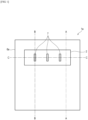
- FIG. 1 is a drawing (schematic drawing) illustrating a sheet-like heater 1a of this invention in Embodiment 1, viewed in a direction of a perpendicular line on the main face thereof.
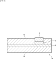
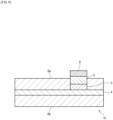
- FIG. 2 is a cross-sectional view (schematic drawing) taken along line A-A in FIG. 1 ;
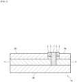
- FIG. 3 is a cross-sectional view (schematic drawing) taken along line B-B in FIG. 1 ;
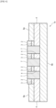
- FIG. 4 is a cross-sectional view (schematic drawing) taken along line C-C in FIG. 1 . All of FIGs. 2 to 4 represent cross-sections taken in a direction parallel to the perpendicular line on the main face of the sheet-like heater 1a of this invention.
- the mode of stacking may be confirmed by observing the cross sections that correspond to FIGs. 2 to 4 , under an optical microscope or a scanning electron microscope.
- the sheet-like heater 1a of this invention in Embodiment 1 has a first insulating layer 6a, a sheet-like porous heat element 4, and a second insulating layer 6b stacked in this order.
- an electrode 2 is present on one main face of the porous heat element 4, while placing a joining aid 3 in between.
- the electrode 2 in this invention although present on at least one main face of the porous heat element 4 as seen above, is not always necessarily in contact with the main face of the porous heat element 4.
- the electrode may resides, as in Embodiment 1, on the main face of the porous heat element 4 while placing the joining aid 3 in between.
- the electrode 2 is not covered with the first insulating layer 6a and the second insulating layer 6b. That is, the outer face of the electrode 2 is at least partially exposed.
- the outer face of the electrode is exposed to the surface as illustrated in FIGs. 1 and 4 .
- the sheet-like heater 1a of this invention in Embodiment 1 has three joined parts 7 and one electrode 2, as illustrated in FIGs. 1 to 4 .
- Each joined part 7 is formed of at least a part of the porous heat element 4, at least a part of the joining aid 3, and at least a part of the electrode 2, which are melted under heating and then allowed to solidify.
- the electrode 2 For example, by placing the electrode 2 on the main face of the porous heat element 4 while placing the joining aid 3 in between, and by welding the electrode 2 under a welding rod pressed on the surface thereof, at least a part of each of the electrode 2, the joining aid 3 and the porous heat element 4 are melted by the heat. After being allowed to cool and solidify, the melted parts will form the joined part 7.
- the porous heat element 4, the joining aid 3, and the electrode 2 are electrically connected through the joined part 7.
- the porous heat element 4, the joining aid 3 and the electrode 2 may be formed of different metals, they are preferably formed of the same metal. This is because the resultant joined part 7 tends to have higher strength, if the porous heat element 4, the joining aid 3 and the electrode 2 are formed of the same metal.
- the major element means a set of one or more elements whose total content (mol%) exceeds 90 mol%, when calculated by adding the content(s) (mol%) of the element(s) that constitute(s) the metal in the order from the most abundant element to the scarcest element. If the content of one element accounts for 90 mol% or more, then the major element is such one element only.
- the sheet-like heater 1a of this invention in Embodiment 1 has three joined parts 7.
- a plurality of joined parts 7 are preferably provided per electrode 2. More specifically, the sheet-like heater of this invention preferably has 2 to 20 joined parts per electrode, and more preferably has 3 to 15 joined parts.
- the sheet-like heater of this invention will have the electrode and the porous heat element more tightly joined, and will have improved flexibility.
- all of the plurality of joined parts if owned by the sheet-like heater of this invention, may have the same size, shape or the like, or different ones.
- the joined parts may be localized in the electrode, or may preferably be distributed, while orderly maintaining a constant spacing.
- the joined part preferably has a dot shape and/or a line shape, when the main face of the sheet-like heater of this invention is viewed from the side the electrode is present.
- the joined part may alternatively have a shape which is not dot or line, such as a plane.
- the joined part preferably looks linear. This is because the joining between the electrode 2 and the porous heat element 4 will be strengthened, and the sheet-like heater of this invention will have improved flexibility under bending.
- Each joined part 7 owned by the sheet-like heater 1a of this invention in Embodiment 1 has a linear shape as illustrated in FIG. 1 , when the main face is viewed from the side the electrode is present.
- the porous heat element 4 will be explained.
- the sheet-like heater of this invention contains the sheet-like porous heat element as an essential element.
- porous heat element 4 applies not only to the porous heat element 4 contained in the sheet-like heater 1a of this invention in Embodiment 1, but also to the porous heat elements owned by the sheet-like heaters of this invention in other Embodiments described later.
- the porous heat element 4 may only be a porous matter that generates heat upon being energized.
- Material for the porous heat element 4 is not specifically limited so far as it can generate heat upon being energized, and is preferably stainless steel (SUS304, SUS316 or SUS316L, for example), which may alternatively be Cu (copper), Al (aluminum), Ni (nickel), nichrome or carbon.
- the porous heat element 4 is preferably formed of a fibrous material.
- the porous heat element 4 formed of the fibrous material may be, for example, sheet-like metal mesh having linear fibers arranged therein near orthogonally, metal fiber nonwoven fabric having metal fibers arranged therein randomly, metal fiber woven fabric, linear metal fiber, and tape-like metal fiber.
- the metal mesh is exemplified by a 200- to 500-mesh metal mesh.
- the metal fiber nonwoven fabric is exemplified by a 1500 g/m 2 stainless steel fiber nonwoven fabric (SUS316L needle punch web, from Nikko Techno, Ltd.).
- the metal fiber woven fabric is exemplified by SUS cloth (Naslon Cloth A, from Nippon Seisen Co., Ltd.).
- the linear metal fiber is exemplified by filament yarn (Naslon 12-2000/3, from Nippon Seisen Co., Ltd.).
- the tape-like metal fiber is exemplified by SUS tape (Naslon Tape B W16, from Nippon Seisen Co., Ltd.).
- the porous heat element 4 is mainly formed of the metal fiber, and more preferably formed of the metal fiber only.
- the metal fiber preferably accounts for 70% by mass or more of the porous heat element 4.
- the percentage of the metal fiber contained in the porous heat element 4 is preferably 80% by mass or more, more preferably 90% by mass or more, even more preferably 95% by mass or more, and yet more preferably 98% by mass or more.
- the porous heat element 4 With the content of the metal fiber in the porous heat element 4 adjusted within the aforementioned ranges, the porous heat element 4 will fully demonstrate the electric conductivity and pyrogenicity.
- the percentage of the metal fiber contained in the porous heat element 4 is determined by the following method.
- a 90 ⁇ m ⁇ 120 ⁇ m field of view in the SEM image is subjected to EDS analysis to identify the presence and the type of the metal fiber, and further subjected to image analysis to determine percentage of area occupied by the metal fiber (excluding voids) in the field of view.
- the obtained percentage is raised to the power of 3/2 to be converted into volume ratio, which is further multiplied by a true specific gravity of the metal fiber, to find the mass ratio.
- the content ratio of the metal fiber is thus determined.
- the percentage of the metal fiber contained in the porous heat element 4 is given by a value determined by adding the content ratios of the individual metal fibers.
- the metal fiber is preferably a metallic fiber whose cross section has an equivalent circle diameter of 2 to 100 ⁇ m (preferably 5 to 20 ⁇ m), and whose length is 2 to 20 mm.
- the porous heat element 4 is preferably a metal fiber nonwoven fabric having such metallic fiber randomly arranged therein (also referred to as metal fiber sheet, hereinafter).
- the metal fiber sheet may be formed solely of the metal fiber possibly with some voids, or may contain, besides the metal fiber, any material other than the metal fiber (for example, resin fiber that functions as a binder), so far as the pyrogenicity will not be adversely affected.
- the binder is exemplified by carbon, glass and silicone resin.
- the metal fibers that compose the metal fiber sheet are preferably connected at a contact point, at least to a degree that allows current to flow therethrough.
- the metal fibers are preferably sintered at high temperatures so as to be partially melted, and then allowed to solidify, thereby being fused at the contact point.
- the metal fiber sheet is preferably a stainless steel fiber sheet for its excellent heat resistance and chemical resistance.
- the stainless steel fiber sheet is exemplified by Tommy Filec SS, from Tomoegawa Corporation.
- the metal fiber sheet preferably has a basis weight of 25 g/m 2 or larger, which is preferably 50 g/m 2 or larger. Meanwhile, the metal fiber sheet has a basis weight of 1000 g/m 2 or smaller, which is more preferably 200 g/m 2 or smaller.
- the metal fiber sheet With the basis weight of the metal fiber sheet adjusted to 25 g/m 2 to 1000 g/m 2 , the metal fiber sheet may have a necessary level of strength, and may make the contact point of the metal fibers relatively uniform.
- the sheet-like heater with use of such metal fiber sheet as the porous heat element, can join the porous heat element and the electrode more tightly, while keeping excellent flexibility.
- the basis weight herein is determined by image observation under an optical microscope, from which the volume per unit area of the metal fiber sheet is estimated, and then by estimating the weight referring to the specific gravity.
- the metal fiber sheet preferably has a density of 1.0 to 5.0 g/cm 3 , which is more preferably 1.4 to 2.0 g/cm 3 , and even more preferably approx. 1.7 g/cm 3 .
- the metal fiber sheet With the density adjusted to 1.0 to 5.0 g/cm 3 , the metal fiber sheet can keep a necessary strength, and can make the contact points among the metal fibers relatively uniform. Hence, the sheet-like heater with use of such metal fiber sheet as the porous heat element will have the porous heat element and the electrode more tightly joined, while keeping excellent flexibility.
- the metal fiber sheet is manufacturable either by dry process for manufacturing nonwoven fabric, or by wet sheet forming.
- a dispersion medium water, organic solvent, etc.
- an organic flocculant is added
- the dry sheet is further sintered at 400 to 1300°C, to obtain the metal fiber sheet.
- the porous heat element 4 preferably has a specific electric resistance of 5 to 3000 ⁇ cm, which is more preferably 10 to 2500 ⁇ cm.
- the porous heat element 4 preferably has a thickness of 10 to 600 ⁇ m, which is more preferably 20 to 150 ⁇ m. With use of the porous heat element 4 having a thickness of 10 to 600 ⁇ m, the sheet-like heater will have the porous heat element and the electrode more tightly joined, while keeping excellent flexibility.
- the thickness of the porous heat element 4 herein is determined as follows.
- a cross section of the sheet-like heater of this invention taken in a direction parallel to a perpendicular line on the main face thereof, is obtained.
- the cross section corresponds to FIGs. 2 to 4 .
- an enlarged photograph (200-fold magnification) of the cross section is acquired with use of an optical microscope, the thickness of porous heat element 4 is measured on the enlarged photograph at randomly selected 100 points, and a simple average value of the measured thicknesses is determined.
- any elements owned by the sheet-like heater of this invention other than the porous heat element 4, will be determined by a similar method.
- Shape and size of the porous heat element 4 are properly adjustable in accordance with the shape and size of an object to be heated.
- the electrode 2 will be explained.
- the sheet-like heater of this invention has the electrode on at least one main face of the sheet-like porous heat element 4.
- the electrode 2 does not necessarily contact with the main face of the porous heat element 4, and for example may reside on the main face of the porous heat element 4 while placing the joining aid in between.
- the description below for the electrode 2 applies not only to the electrode 2 contained in the sheet-like heater 1a of this invention in Embodiment 1, but also to the electrodes owned by the sheet-like heaters of this invention that involve other Embodiments described later.
- the electrode 2 may only have a mode that can be connected with an external power source, and can feed therethrough electricity fed from the external power source to the porous heat element 4.
- Material for the electrode 2 is not specifically limited.
- the material may be Cu (copper), Ag (silver), Au (gold) and so forth, and preferably stainless steel (SUS304, SUS316 or SUS316L, for example).
- the electrode 2 may be formed, for example, of metal foil, sheet-like metal mesh having linear fibers arranged therein near orthogonally, metal fiber nonwoven fabric having metal fibers arranged therein randomly, metal fiber woven fabric, linear metal fiber, and tape-like metal fiber.
- the metal mesh is exemplified by a 200- to 500-mesh metal mesh.
- the metal fiber nonwoven fabric is exemplified by a 1500 g/m 2 stainless steel fiber nonwoven fabric (SUS316L needle punch web, from Nikko Techno, Ltd.).
- the metal fiber woven fabric is exemplified by SUS cloth (Naslon Cloth A, from Nippon Seisen Co., Ltd.).
- the linear metal fiber is exemplified by filament yarn (Naslon 12-2000/3, from Nippon Seisen Co., Ltd.).
- the tape-like metal fiber is exemplified by SUS tape (Naslon Tape B W16, from Nippon Seisen Co., Ltd.).
- the electrode 2 has a connection part (not illustrated) for an external power source, and is structured to energize the porous heat element 4 through the electrode 2 from the external power source.
- the external power source and the electrode 2 may be connected through a cable with a crimp terminal.
- Shape and size of the electrode 2 may only be those allowed for provision of the connection part for the external power source, and sufficient energization of the porous heat element 4, and are properly adjustable.
- the electrode 2 preferably has a specific electric resistance of 5 to 100 ⁇ cm, which is more preferably 10 to 90 ⁇ cm.
- the electrode 2 is preferably formed of a fibrous material, and more preferably formed of a woven fabric made of twisted yarn of the metal fiber, or a metal fiber woven fabric.
- the porous heat element and the electrode are less likely to separate from the joined part even if external force is applied to the sheet-like heater of this invention, for its appropriate flexibility and strength.
- the woven fabric made of twisted yarn of the metal fiber or the metal fiber woven fabric although allowed for use of fiber other than the metal fiber as the constituent, preferably formed of the metal fiber, and more preferably formed of the metal fiber only.
- the metal fiber preferably accounts for 70% by mass or more of the electrode 2.
- the percentage of the metal fiber contained in the electrode 2 is preferably 80% by mass or more, more preferably 90% by mass or more, even more preferably 95% by mass or more, and yet more preferably 98% by mass or more.
- the woven fabric made of twisted yarn of the metal fiber, or the metal fiber woven fabric may have void remained therein.
- the woven fabric made of twisted yarn of the metal fiber, or the metal fiber woven fabric may contain a material other than the metal fiber (for example, resin fiber that can function as a binder).
- the metal fiber that constitutes a woven fabric made of twisted yarn of the metal fiber, or the metal fiber that constitutes a metal fiber woven fabric may have a cross section whose equivalent circle diameter is 1 to 50 ⁇ m (preferably 2 to 30 ⁇ m).
- the equivalent circle diameter of the cross section of the metal fiber herein means a value determined by acquiring a 1000-fold magnified SEM image of the cross section of the electrode 2 under a scanning electron microscope (SEM), by measuring the diameter of the metal fibers on the SEM image at randomly selected 30 points, and by calculating a simple average value of the measured diameters.
- SEM scanning electron microscope
- the electrode can join with the joining aid or the porous heat element more tightly, while improving the flexibility of the sheet-like heater of this invention.
- the electrode 2 preferably has a thickness of 0.5 to 3 mm. With the thickness thus adjusted, the electrode can join with the joining aid or the porous heat element more tightly, while improving the flexibility of the sheet-like heater of this invention.
- the thickness of the electrode 2 is preferably adjusted so that the electrode 2 protrudes out from the outer face of the first insulating layer 6a. This facilitates connection work for the electrode 2 and the external power source, and makes various connection methods more available.
- the joining aid 3 will be explained.
- the sheet-like heater of this invention in Embodiment 1 has the joining aid 3 between the porous heat element 4 and the electrode 2.
- the sheet-like heater of this invention preferably has the joining aid 3 between the electrode 2 and the porous heat element 4.
- joining aid 3 applies not only to the joining aid 3 contained in the sheet-like heater 1a of this invention in Embodiment 1, but also to the joining aids 3 owned by the sheet-like heaters of this invention in other Embodiments described later.
- Material for the joining aid 3 is not specifically limited so far as it is electroconductive, and may typically be Cu (copper), Al (aluminum), Ni (nickel), nichrome, carbon, Fe (iron) or Cr (chromium). Stainless steel is preferred.
- Material for the joining aid 3 is properly selected while considering joining strength and easiness of joining between the electrode 2 and the porous heat element 4, as well as the flexibility or the like of the sheet-like heater of this invention.
- the joining aid 3 may typically be metal foil, sheet-like metal mesh, metal fiber nonwoven fabric, metal fiber woven fabric, linear metal fiber, or tape-like metal fiber.
- the metal mesh is exemplified by a 200- to 500-mesh metal mesh.
- the metal fiber nonwoven fabric is exemplified by a 1500 g/m 2 stainless steel fiber nonwoven fabric (SUS316L needle punch web, from Nikko Techno, Ltd.).
- the metal fiber woven fabric is exemplified by SUS cloth (Naslon Cloth A, from Nippon Seisen Co., Ltd.).
- the linear metal fiber is exemplified by filament yarn (Naslon 12-2000/3, from Nippon Seisen Co., Ltd.).
- the tape-like metal fiber is exemplified by SUS tape (Naslon Tape B W16, from Nippon Seisen Co., Ltd.).
- the joining aid 3 is preferably the metal foil, and more preferably a stainless steel foil.
- the joining aid 3 in the form of metal foil facilitates weld-joining of the joining aid 3 with the electrode 2 and the porous heat element 4.
- both the electrode 2 and the porous heat element 4 are formed of stainless steel
- use of the joining aid 3 again formed of stainless steel will make it easier to form the joined part 7.
- the joined part 7 With the electrode 2, the porous heat element 4 and the joining aid 3, all formed of stainless steel of the same composition, the joined part 7 will be more easily formed.
- the electrode 2 and the porous heat element 4 are formed of stainless steel, use of a stainless steel foil for the joining aid 3 will make it more easier to form the joined part 7.
- the joined part 7 With the electrode 2, the porous heat element 4, and the joining aid 3 in the form of stainless steel foil, all formed of stainless steel of the same composition, the joined part 7 will be more easily formed. In this case, even a small joined part 7 can easily achieve a necessary joining strength among the electrode 2 and the joining aid 3 and the porous heat element 4, thereby enhancing the flexibility of the sheet-like heater 1 of this invention.
- the joining aid 3 is preferably made of a nickel alloy.
- the area of the main face of the joining aid 3 opposed to the electrode 2 is preferably equal to or larger than the area of the main face of the electrode 2 opposed to the joining aid 3, since this makes it possible to form one or more joined parts 7, without paying special attention to the layout of the joining aid 3.
- the joining aid 3 preferably has a specific electric resistance of 5 to 100 ⁇ cm, which is more preferably 10 to 90 ⁇ cm.
- the joining aid 3 preferably has a thickness of 10 to 100 ⁇ m.
- the joining aid 3 With the thickness adjusted to 10 to 100 ⁇ m, the joining aid 3 will easily achieve a necessary joining strength between the porous heat element 4 and the electrode 2, while keeping the flexibility of the sheet-like heater 1 of this invention. While keeping the flexibility of the sheet-like heater 1 of this invention, a necessary level of the joining strength among the porous heat element 4, the joining aid 3 and the electrode 2 may be achieved.
- the first insulating layer 6a and the second insulating layer 6b will be explained.
- the sheet-like heater of this invention preferably has the first insulating layer 6a and/or the second insulating layer 6b.
- the sheet-like heater of this invention preferably has the first insulating layer 6a, the porous heat element 4, and the second insulating layer 6b stacked therein in this order, as in Embodiment 1.
- first insulating layer 6a and the second insulating layer 6b applies not only to the first insulating layer 6a and the second insulating layer 6b contained in the sheet-like heater 1a of this invention in Embodiment 1, but also to the first insulating layers and the second insulating layers that can be owned by the sheet-like heaters of this invention that involve other Embodiments described later.
- the first insulating layer 6a and the second insulating layer 6b play a role of electrically isolating the porous heat element 4 from other components, and are therefore preferably sheet-like components formed of a material with high insulating performance.
- any of the insulating layers that is placed closer to a surface of an object to be heated, when the sheet-like heater 1a of this invention is placed on the surface of the object to be heated preferably has heat conductivity as well as insulating property.
- the first insulating layer 6a and the second insulating layer 6b may preferably be formed, for example, of PET (polyethylene terephthalate), PI (polyimide), PP (polypropylene), PE (polyethylene), PEN (polyethylene naphthalate), TAC (triacetyl cellulose), silicone resin, ceramic or the like, since they have high insulating property.
- PET polyethylene terephthalate
- PI polyimide
- PP polypropylene
- PE polyethylene
- PEN polyethylene naphthalate
- TAC triacetyl cellulose
- silicone resin ceramic or the like, since they have high insulating property.
- the first insulating layer 6a and/or the second insulating layer 6b formed of PI (polyimide) are preferably used for their excellent heat resistance and insulating property.
- each of the first insulating layer 6a and the second insulating layer 6b is preferably, but not specifically limited to, 50 to 700 ⁇ m, which is more preferably 100 to 600 ⁇ m, and even more preferably 200 to 500 ⁇ m.
- Shape and size of the first insulating layer 6a and the second insulating layer 6b are not specifically limited. Considering that the first insulating layer 6a and the second insulating layer 6b play a role of electrically isolating the porous heat element 4 from the other components, the size of the main faces of the first insulating layer 6a and second insulating layer 6b is usually equal to or larger than the main face of the porous heat element 4.
- the main faces of the first insulating layer 6a and the porous heat element 4, and, the main faces of the porous heat element 4 and the second insulating layer 6b, may be joined typically with use of an adhesive.
- Some other layer may be interposed between the first insulating layer 6a and the porous heat element 4, or between the porous heat element 4 and the second insulating layer 6b.
- the first insulating layer 6a and the second insulating layer 6b may be formed of the same material, or different materials.
- the first insulating layer 6a and the second insulating layer 6b may have the same thickness, or different thicknesses.
- the electrode 2 is not covered with the first insulating layer 6a and the second insulating layer 6b.
- the electrode 2 is not covered with the first insulating layer 6a, and instead, the outer face of the electrode 2 is exposed as viewed from the outer face side of the insulating layer 6a. That is, the first insulating layer 6a has an opening formed therein, so as to expose therein the outer face of the electrode 2.
- the sheet-like heater 1a of this invention in Embodiment 1 has the electrode 2 on one main face of the sheet-like porous heat element 4, while placing the joining aid 3 in between.
- the sheet-like heater of this invention in Embodiment 1 may have other component between the electrode 2 and the joining aid 3, or between the joining aid 3 and the porous heat element 4, so far as formation of the joined part 7 is not interfered.
- the thickness of the sheet-like heater of this invention is preferably 150 to 500 ⁇ m, and more preferably 300 to 400 ⁇ m.
- Embodiment 2 of the sheet-like heater of this invention will be explained while referring to the attached drawings.
- Embodiment 2 relates to a sheet-like heater having a sheet-like porous heat element, the sheet-like heater having:
- Embodiment 2 relates to the sheet-like heater of this invention, which is a preferred mode further having the first insulating layer, the second insulating layer, the joining aid and the reinforcing member.
- the joined part in this case is formed as a result of fusion of at least a part of the reinforcing member, at least a part of the porous heat element, at least a part of the joining aid, and at least a part of the electrode, followed by solidification.
- the reinforcing member, the porous heat element, the joining aid, and the electrode are electrically connected through the joined part.
- FIG. 5 A drawing (schematic drawing) of the sheet-like heater 1b of this invention in Embodiment 2, viewed in a direction of a perpendicular line on the main face thereof, will be same as FIG. 1 .
- FIG. 6 is a SEM image of a joined part and the periphery of the sheet-like heater 1b of this invention in Embodiment 2, obtained by observing a cross section taken along a direction parallel to a perpendicular line on the main face of the sheet-like heater 1b of this invention, under a scanning electron microscope (SEM).
- SEM scanning electron microscope
- the electrode 2 used herein was a tape-like metal fiber (tape B W16, from Nippon Seisen Co., Ltd.); each of the joining aid 3 and the reinforcing member 8 used herein was a 30- ⁇ m thick stainless steel foil; and the porous heat element 4 used herein was a stainless steel fiber sheet (Tommy Filec SS, from Tomoegawa Corporation).
- the reinforcing member 8, the porous heat element 4, the joining aid 3 and the electrode 2 were stacked in this order, and the stack was spot-welded from the top face of the electrode 2, to form the joined part 7.
- FIG. 6 helps to understand that a part of the electrode 2, a part of the joining aid 3, a part of the porous heat element 4, and a part of the reinforcing member 8 fused and then solidified, to form the joined part 7.
- the presence of the reinforcing member 8 enabled formation of the joined part 7 having a thickness of 150 ⁇ m or larger.
- the joined part 7, thus having a sufficient thickness, is considered to be less breakable, even if external force is applied to the sheet-like heater 1b of this invention.
- the reinforcing member 8 will be explained.
- the sheet-like heater of this invention in Embodiment 2 has the reinforcing member 8, on the main face of the porous heat element 4 on the side having no electrode 2 present thereon.
- the sheet-like heater of this invention preferably has the reinforcing member 8 on the main face of the porous heat element 4 on the side having no electrode 2 present thereon, as in Embodiment 2.
- reinforcing member 8 applies not only to the reinforcing member 8 contained in the sheet-like heater 1b of this invention in Embodiment 2, but also to the reinforcing member 8 that can be owned by the sheet-like heaters of this invention that involve other Embodiments described later.
- Material for the reinforcing member 8 is not specifically limited, to which either inorganic or organic substance is applicable, so long as it is flexible and durable to temperature (heating temperature) under heat generated by the porous heat element 4 contained in the sheet-like heater 1b of this invention.
- Embodiment 2 relates to a mode where the reinforcing member 8 is formed of metal which is one of the inorganic substance.
- the reinforcing member 8 in Embodiment 2 is formed of metal, so that the joined part 7 owned by the sheet-like heater 1b of this invention in Embodiment 2 is formed of at least a part of reinforcing member, at least a part of the porous heat element, at least a part of the joining aid, and at least a part of the electrode which were fused and then solidified.
- the reinforcing member, the porous heat element, the joining aid, and the electrode are electrically connected through the joined part.
- the joined part owned by the sheet-like heater of this invention of this mode is formed of at least a part of the porous heat element, at least a part of the joining aid, and at least a part of the electrode which were fused and then solidified.
- Material for the reinforcing member 8 may be same as, or different from the joining aid 3.
- the material for the reinforcing member 8 is preferably the same metal for the porous heat element 4, more preferably the same metal for the porous heat element 4 and the joining aid 3, and even more preferably the same metal for the porous heat element 4, the joining aid 3 and the electrode 2.
- the material for the reinforcing member 8 is more preferably stainless steel (SUS304, SUS316 or SUS316L, for example).
- the reinforcing member 8 may be embodied typically in the form of metal foil, sheet-like metal mesh, metal fiber nonwoven fabric, metal fiber woven fabric, linear metal fiber, or tape-like metal fiber.
- the metal mesh is exemplified by a 200- to 500-mesh metal mesh.
- the metal fiber nonwoven fabric is exemplified by a 1500 g/m 2 stainless steel fiber nonwoven fabric (SUS316L needle punch web, from Nikko Techno, Ltd.).
- the metal fiber woven fabric is exemplified by SUS cloth (Naslon Cloth A, from Nippon Seisen Co., Ltd.).
- the linear metal fiber is exemplified by filament yarn (Naslon 12-2000/3, from Nippon Seisen Co., Ltd.).
- the tape-like metal fiber is exemplified by SUS tape (Naslon Tape B W16, from Nippon Seisen Co., Ltd.).
- the reinforcing member 8 is preferably the metal foil, and more preferably a stainless steel foil.
- the reinforcing member 8 in the form of metal foil can fill the voids of the porous heat element 4 to strengthen the joined part 7, when weld-joining a stack of the electrode 2, the joining aid 3, the porous heat element 4, and the reinforcing member 8.
- the presence of the reinforcing member 8 can make the porous heat element and the electrode less likely to separate from the joined part, even if external force is applied to the sheet-like heater.
- Embodiment 2 relates to a mode where a part of the reinforcing member 8 forms the joined part 7.
- At least a part of the electrode 2, at least a part of the joining aid 3, at least a part of the porous heat element 4, and at least a part of the reinforcing member 8 are integrated to form the joined part.
- Size and shape of the reinforcing member 8 are not specifically limited.
- the area of the main face of the reinforcing member 8 opposed to the electrode 2 is preferably equal to or larger than the area of the main face of the electrode 2 opposed to the reinforcing member 8.
- the area of the main face of the reinforcing member 8 opposed to the joining aid 3 is preferably equal to or larger than the area of the main face of the joining aid 3 opposed to the reinforcing member 8. This is because one or more joined parts 7 may be formed without paying special attention to the layout of the reinforcing members 8, and because more strengthened joined part 7 may be formed.
- the reinforcing member 8 preferably has a thickness of 10 to 100 ⁇ m. With the thickness of the reinforcing member 8 adjusted to 10 to 100 ⁇ m, more strengthened joined part 7 will be formed easily.
- Embodiment 3 of the sheet-like heater of this invention will be explained while referring to the attached drawings.
- Embodiment 3 relates to a sheet-like heater having a sheet-like porous heat element, the sheet-like heater having:
- Embodiment 3 relates to the sheet-like heater of this invention, which is a preferred mode further having the first insulating layer, the second insulating layer, the joining aid and the protecting member.
- the joined part in this case is formed as a result of fusion of at least a part of the porous heat element, at least a part of the joining aid, at least a part of the electrode, and at least a part of the protecting member, followed by solidification.
- the porous heat element, the joining aid, the electrode, and the protecting member are electrically connected through the joined part.
- FIG. 7 is a drawing (schematic drawing) illustrating the sheet-like heater 1c of this invention in Embodiment 3, viewed in a direction of a perpendicular line on the main face thereof.
- FIG. 8 is a cross-sectional view (schematic drawing) taken along line D-D in FIG. 7 ;
- FIG. 9 is a cross-sectional view (schematic drawing) taken along line E-E in FIG. 7 ;
- FIG. 10 is a cross-sectional view (schematic drawing) taken along line F-F in FIG. 7 . All of FIGs. 8 to 10 illustrate cross sections taken in directions parallel to the perpendicular line on the main face of the sheet-like heater 1c of this invention.
- the sheet-like heater 1c of this invention in Embodiment 3 has a protecting member 9 on the outer side of the electrode 2, that is on the main face of the electrode 2 on the side away from the joining aid 3.
- the protecting member 9 is provided to protect the electrode 2. With the protecting member 9 thus provided, the electrode 2 will be less likely to degrade after long-term use of the sheet-like heater 1c of this invention, and will tend to be tightly joined to the joined part 7.
- the presence of the protecting member 9 enables protection of the outer face of the electrode 2, even under external force applied to the sheet-like heater 1c of this invention, whereby the electrode 2, the joining aid 3, and the porous heat element 4 will more easily keep the joining with the joined part 7.
- the protecting member 9 is not specifically limited so far as it can protect the electrode 2.
- Material for the protecting member 9 may be insulating material, conductive material or semiconductor, without special limitation.
- the protecting member 9 in the sheet-like heater 1c of this invention in Embodiment 3 is formed of metal.
- the material for the protecting member 9 is preferably metal, and more preferably stainless steel (SUS304, SUS316 or SUS316L, for example).
- the protecting member 9 may typically be metal foil, sheet-like metal mesh, metal fiber nonwoven fabric, metal fiber woven fabric, linear metal fiber, or tape-like metal fiber.
- the metal mesh is exemplified by a 200- to 500-mesh metal mesh.
- the metal fiber nonwoven fabric is exemplified by a 1500 g/m 2 stainless steel fiber nonwoven fabric (SUS316L needle punch web, from Nikko Techno, Ltd.).
- the metal fiber woven fabric is exemplified by SUS cloth (Naslon Cloth A, from Nippon Seisen Co., Ltd.).
- the linear metal fiber is exemplified by filament yarn (Naslon 12-2000/3, from Nippon Seisen Co., Ltd.).
- the tape-like metal fiber is exemplified by SUS tape (Naslon Tape B W16, from Nippon Seisen Co., Ltd.).
- the protecting member 9 is preferably the metal foil, and more preferably a stainless steel foil.
- the electrode 2 when joined with the protecting member 9 formed of a conductive material, will have increased electric connection points or electric connection area with the porous heat element 4, and this demonstrates an effect of stabilizing electric connection between the electrode 2 and the porous heat element 4.
- the electrode 2 With the protecting member 9 thus provided, the electrode 2 will be made not only connectable directly with the joining aid 3, but also connectable via the protecting member 9 with the joining aid 3.
- the protecting member 9 may be joined with the electrode 2 or not, and is preferably joined with the electrode 2.
- the main face thereof is preferably equivalent to, or larger than the main face of the electrode 2.
- Shape of the protecting member 9 is not specifically limited.
- the protecting member 9 preferably has a thickness of 10 to 100 ⁇ m.
- Embodiment 4 of the sheet-like heater of this invention will be explained while referring to the attached drawing.
- FIG. 11 is a drawing (schematic drawing) illustrating a sheet-like heater 1d of this invention in Embodiment 4, viewed in a direction of a perpendicular line on the main face thereof.
- Embodiment 4 relates to a mode similar to Embodiment 1 or Embodiment 2, which is all the same with Embodiment 1 or Embodiment 2 except for the joined part 7.
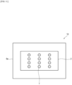
- the sheet-like heater 1d of this invention in Embodiment 4 relates to a mode where twelve dot-like joined parts 7 are distributed.
- FIG. 12 is a drawing (schematic drawing) illustrating a sheet-like heater 1e of this invention in Embodiment 5, viewed in a direction of a perpendicular line on the main face thereof.
- Embodiment 5 relates to a mode similar to Embodiment 1 or Embodiment 2, which is all the same with Embodiment 1 or Embodiment 2 except for the joined part 7.
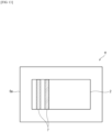
- the sheet-like heater 1e of this invention in Embodiment 5 relates to a mode having one linear joined part 7.
- FIG. 13 is a drawing (schematic drawing) illustrating a sheet-like heater 1f of this invention in Embodiment 6, viewed in a direction of a perpendicular line on the main face thereof.
- Embodiment 6 relates to a mode similar to Embodiment 1 or Embodiment 2, which is all the same with Embodiment 1 or Embodiment 2 except for the joined part 7.
- the sheet-like heater 1f of this invention in Embodiment 6 relates to a mode having two linear joined parts 7.
- the joined parts 7 in Embodiment 6 are localized.
- Manufacturing method of the sheet-like heater of this invention (referred to as manufacturing method of this invention, hereinafter) will be explained while referring to FIGs. 14 and 15 .
- the manufacturing method of this invention explained below is an example of a preferred manufacturing method.
- the sheet-like heater of this invention is not limited to the one manufactured by the manufacturing method of this invention described below.
- FIGs. 14 and 15 are drawings explaining the method for manufacturing the sheet-like heater 1b in Embodiment 2.
- the individual layers may be tightly contacted typically with use of an adhesive.
- a part of the first insulating layer 6a is cut off typically with use of a cutter to form an opening 10, in which the joining aid 3 exposes ( FIG. 15 ).
- Means for joining may be any of means known by those skilled in the art, which is typically welding processing.
- the sheet-like heater of this invention is typically applicable to pipe, film forming apparatus, hot air generator or the like.
Landscapes
- Resistance Heating (AREA)
- Surface Heating Bodies (AREA)
Abstract
Description
- This invention relates to a sheet-like heater.
- Several types of sheet-like heater have been proposed.
- For example,
Patent Literature 1 discloses a sheet heater that includes a plurality of heat elements formed of thin stainless steel sheet, arranged in parallel, and an insulating base stacked on at least either face of these heat elements, in which each heat element has a power input terminal tightly joined to one end thereof, and has a connection part for connection with the adjacent heat element formed at the other end thereof, the connection part having a brazing material and a terminal piece stacked therein, with the power input terminal tightly joined to the end of each heat element while placing the electroconductive brazing material in between. - [Patent Literature 1]
JP 3127850 U - A heater for heating an object to be heated, having a curved face such as pipe, is necessarily flexible so as to make it conformable to the object to be heated. Another requirement is that the heat element and the electrode of the heater remain tightly joined, even under an external force such as vibration or agitation applied to a joined part. Excessive tightness of joining between the heat element and the electrode has, however, reduced the flexibility of the heater in some cases.
- It is therefore an object of this invention to provide a sheet-like heater in which the heat element and the electrode are tightly joined, but excels in flexibility.
- This invention encompasses items (1) to (11) below.
- (1) A sheet-like heater having a sheet-like porous heat element, the sheet-like heater including:
- an electrode present on at least one main face of the porous heat element; and
- at least one joined part formed of the porous heat element and the electrode which are at least partially melted under heating and then allowed to solidify, whereby the joined part electrically connects the porous heat element and the electrode.
- (2) The sheet-like heater according to (1), including:
- a first insulating layer;
- the sheet-like porous heat element; and
- a second insulating layer, which are stacked in this order, and
- at least a part of the electrode is not covered with the first insulating layer and the second insulating layer.
- (3) The sheet-like heater according to (1) or (2), further including a joining aid between the porous heat element and the electrode, wherein
the joined part is formed of the porous heat element, the joining aid and the electrode which are at least partially melted under heating and then allowed to solidify, whereby the joined part electrically connects the porous heat element, the joining aid and the electrode. - (4) The sheet-like heater according to (3), further including a reinforcing member on the main face of the porous heat element on the side having no electrode present thereon, wherein
the joined part is formed of the reinforcing member, the porous heat element, the joining aid and the electrode which are at least partially melted under heating and then allowed to solidify, whereby the joined part electrically connects the reinforcing member, the porous heat element, the joining aid and the electrode. - (5) The sheet-like heater according to (1) or (2), further including a reinforcing member on the main face of the porous heat element on the side having no electrode present thereon, wherein
the joined part is formed of the reinforcing member, the porous heat element and the electrode which are at least partially melted under heating and then allowed to solidify. - (6) The sheet-like heater according to any one of (1) to (5), having a plurality of the joined parts per electrode.
- (7) The sheet-like heater according to any one of (1) to (6), wherein the joined part has a dot shape and/or a line shape, when the main face is viewed from the side the electrode is present.
- (8) The sheet-like heater according to any one of (1) to (7), wherein the electrode and the porous heat element are formed of the same kind of metal.
- (9) The sheet-like heater according to any one of (1) to (7), wherein the electrode and the porous heat element are formed of different kinds of metal.
- (10) The sheet-like heater according to any one of (1) to (9), wherein the electrode contains a metal fiber.
- (11) The sheet-like heater according to any one of (1) to (10), wherein the porous heat element contains a metal fiber.
- This invention can provide a sheet-like heater in which the heat element and the electrode are tightly joined, but excels in flexibility.
-
- [
FIG. 1] FIG. 1 is a drawing (schematic drawing) illustrating a sheet-like heater 1a of this invention inEmbodiment 1, viewed in a direction of a perpendicular line on the main face thereof. - [
FIG. 2] FIG. 2 is a cross-sectional view (schematic drawing) taken along line A-A inFIG. 1 . - [
FIG. 3] FIG. 3 is a cross-sectional view (schematic drawing) taken along line B-B inFIG. 1 . - [
FIG. 4] FIG. 4 is a cross-sectional view (schematic drawing) taken along line C-C inFIG. 1 . - [
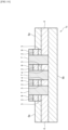
FIG. 5] FIG. 5 is a cross-sectional view of a sheet-like heater 1b of this invention inEmbodiment 2, taken in a direction parallel to a perpendicular line on the main face thereof. - [
FIG. 6] FIG. 6 is a SEM image of a cross section of a joined part and the periphery inEmbodiment 2, observed under a scanning electron microscope (SEM). - [
FIG. 7] FIG. 7 is a drawing (schematic drawing) of a sheet-like heater 1c of this invention inEmbodiment 3, viewed in the direction of a perpendicular line on the main face thereof. - [
FIG. 8] FIG. 8 is a cross-sectional view (schematic drawing) taken along line D-D inFIG. 7 . - [
FIG. 9] FIG. 9 is a cross-sectional view (schematic drawing) taken along line E-E inFIG. 7 . - [
FIG. 10] FIG. 10 is a cross-sectional view (schematic drawing) taken along line F-F inFIG. 7 . - [
FIG. 11] FIG. 11 is a drawing (schematic drawing) of a sheet-like heater 1d of this invention inEmbodiment 4, viewed in the direction of a perpendicular line on the main face thereof. - [
FIG. 12] FIG. 12 is a drawing (schematic drawing) of a sheet-like heater 1e of this invention in Embodiment 5, viewed in the direction of a perpendicular line on the main face thereof. - [
FIG. 13] FIG. 13 is a drawing (schematic drawing) of a sheet-like heater 1f of this invention in Embodiment 6, viewed in the direction of a perpendicular line on the main face thereof. - [
FIG. 14] FIG. 14 is a drawing illustrating a method for manufacturing the sheet-like heater inEmbodiment 2. - [
FIG. 15] FIG. 15 is another drawing illustrating a method for manufacturing the sheet-like heater inEmbodiment 2. - This invention will be explained.
- A sheet-like heater of this invention has a sheet-like porous heat element, the sheet-like heater includes: an electrode present on at least one main face of the porous heat element; and a joined part formed of the porous heat element and the electrode which are at least partially melted under heating and then allowed to solidify, whereby the joined part electrically connects the porous heat element and the electrode.
- Embodiments of the sheet-like heater of this invention will be explained while referring to the attached drawings.
- Note that the Embodiments explained below are preferred examples of the sheet-like heater of this invention, to which this invention is by no means limited. Also sizes and shapes seen in the drawings are merely illustrative, to which this invention is by no means limited.
-
Embodiment 1 of the sheet-like heater of this invention will be explained while referring to the attached drawings. -
Embodiment 1 relates to a sheet-like heater having a sheet-like porous heat element, the sheet-like heater having: - a first insulating layer;
- the sheet-like porous heat element; and
- a second insulating layer, which are stacked in this order,
- wherein,
- an electrode is present on at least one main face of the porous heat element,
- a joining aid is further provided between the porous heat element and the electrode,
- at least a part of the electrode is not covered with the first insulating layer and the second insulating layer, and
- the sheet-like heater has a joined part formed of the porous heat element, the joining aid and the electrode which are at least partially melted under heating and then allowed to solidify, whereby the joined part electrically connects the porous heat element, the joining aid and the electrode.
- That is,
Embodiment 1 is a preferred embodiment of a sheet-like heater of this invention, further having the first insulating layer, the second insulating layer and the joining aid. - The joined part in this case is formed of at least a part of the porous heat element, at least a part of the joining aid, and at least a part of the electrode which are melted under heating, and then allowed to solidify.
- The porous heat element, the joining aid, and the electrode are electrically connected through the joined part.
-
FIG. 1 is a drawing (schematic drawing) illustrating a sheet-like heater 1a of this invention inEmbodiment 1, viewed in a direction of a perpendicular line on the main face thereof.FIG. 2 is a cross-sectional view (schematic drawing) taken along line A-A inFIG. 1 ;FIG. 3 is a cross-sectional view (schematic drawing) taken along line B-B inFIG. 1 ; andFIG. 4 is a cross-sectional view (schematic drawing) taken along line C-C inFIG. 1 . All ofFIGs. 2 to 4 represent cross-sections taken in a direction parallel to the perpendicular line on the main face of the sheet-like heater 1a of this invention. - Note that in the sheet-like heater of this invention that involves
Embodiment 1 and other Embodiments described later, the mode of stacking may be confirmed by observing the cross sections that correspond toFIGs. 2 to 4 , under an optical microscope or a scanning electron microscope. - As illustrated in
FIGs. 1 to 4 , the sheet-like heater 1a of this invention inEmbodiment 1 has a first insulatinglayer 6a, a sheet-likeporous heat element 4, and a secondinsulating layer 6b stacked in this order. - On one main face of the
porous heat element 4, anelectrode 2 is present while placing a joiningaid 3 in between. - The
electrode 2 in this invention, although present on at least one main face of theporous heat element 4 as seen above, is not always necessarily in contact with the main face of theporous heat element 4. The electrode may resides, as inEmbodiment 1, on the main face of theporous heat element 4 while placing the joiningaid 3 in between. - Now, at least a part of the
electrode 2 is not covered with the first insulatinglayer 6a and the second insulatinglayer 6b. That is, the outer face of theelectrode 2 is at least partially exposed. In the sheet-like heater 1a of this invention inEmbodiment 1, the outer face of the electrode is exposed to the surface as illustrated inFIGs. 1 and4 . - The sheet-
like heater 1a of this invention inEmbodiment 1 has three joinedparts 7 and oneelectrode 2, as illustrated inFIGs. 1 to 4 . - Each joined
part 7 is formed of at least a part of theporous heat element 4, at least a part of the joiningaid 3, and at least a part of theelectrode 2, which are melted under heating and then allowed to solidify. - For example, by placing the
electrode 2 on the main face of theporous heat element 4 while placing the joiningaid 3 in between, and by welding theelectrode 2 under a welding rod pressed on the surface thereof, at least a part of each of theelectrode 2, the joiningaid 3 and theporous heat element 4 are melted by the heat. After being allowed to cool and solidify, the melted parts will form the joinedpart 7. - The
porous heat element 4, the joiningaid 3, and theelectrode 2 are electrically connected through the joinedpart 7. - Although the
porous heat element 4, the joiningaid 3 and theelectrode 2 may be formed of different metals, they are preferably formed of the same metal. This is because the resultant joinedpart 7 tends to have higher strength, if theporous heat element 4, the joiningaid 3 and theelectrode 2 are formed of the same metal. - Note that the same metal herein means that the major element is the same.
- The major element means a set of one or more elements whose total content (mol%) exceeds 90 mol%, when calculated by adding the content(s) (mol%) of the element(s) that constitute(s) the metal in the order from the most abundant element to the scarcest element. If the content of one element accounts for 90 mol% or more, then the major element is such one element only.
- As described above, the sheet-
like heater 1a of this invention inEmbodiment 1 has three joinedparts 7. - In the sheet-like heater of this invention that involves
Embodiment 1 and other Embodiments described later, a plurality of joinedparts 7 are preferably provided perelectrode 2. More specifically, the sheet-like heater of this invention preferably has 2 to 20 joined parts per electrode, and more preferably has 3 to 15 joined parts. - This is because, with the plurality of joined parts provided per electrode, the sheet-like heater of this invention will have the electrode and the porous heat element more tightly joined, and will have improved flexibility.
- In the sheet-like heater of this invention that involves
Embodiment 1 and other Embodiments described later, all of the plurality of joined parts, if owned by the sheet-like heater of this invention, may have the same size, shape or the like, or different ones. - In a case where the sheet-like heater of this invention has a plurality of joined parts per electrode, the joined parts may be localized in the electrode, or may preferably be distributed, while orderly maintaining a constant spacing.
- In the sheet-like heater of this invention that involves
Embodiment 1 and other Embodiments described later, the joined part preferably has a dot shape and/or a line shape, when the main face of the sheet-like heater of this invention is viewed from the side the electrode is present. Note that the joined part may alternatively have a shape which is not dot or line, such as a plane. - When the main face of the sheet-like heater of this invention is viewed from the side the electrode is present, the joined part preferably looks linear. This is because the joining between the
electrode 2 and theporous heat element 4 will be strengthened, and the sheet-like heater of this invention will have improved flexibility under bending. - Each joined
part 7 owned by the sheet-like heater 1a of this invention inEmbodiment 1 has a linear shape as illustrated inFIG. 1 , when the main face is viewed from the side the electrode is present. - The
porous heat element 4 will be explained. - The sheet-like heater of this invention contains the sheet-like porous heat element as an essential element.
- Note that the following description regarding the
porous heat element 4 applies not only to theporous heat element 4 contained in the sheet-like heater 1a of this invention inEmbodiment 1, but also to the porous heat elements owned by the sheet-like heaters of this invention in other Embodiments described later. - The
porous heat element 4 may only be a porous matter that generates heat upon being energized. - Material for the
porous heat element 4 is not specifically limited so far as it can generate heat upon being energized, and is preferably stainless steel (SUS304, SUS316 or SUS316L, for example), which may alternatively be Cu (copper), Al (aluminum), Ni (nickel), nichrome or carbon. - The
porous heat element 4 is preferably formed of a fibrous material. - The
porous heat element 4 formed of the fibrous material may be, for example, sheet-like metal mesh having linear fibers arranged therein near orthogonally, metal fiber nonwoven fabric having metal fibers arranged therein randomly, metal fiber woven fabric, linear metal fiber, and tape-like metal fiber. - More specifically, the metal mesh is exemplified by a 200- to 500-mesh metal mesh.
- The metal fiber nonwoven fabric is exemplified by a 1500 g/m2 stainless steel fiber nonwoven fabric (SUS316L needle punch web, from Nikko Techno, Ltd.).
- The metal fiber woven fabric is exemplified by SUS cloth (Naslon Cloth A, from Nippon Seisen Co., Ltd.).
- The linear metal fiber is exemplified by filament yarn (Naslon 12-2000/3, from Nippon Seisen Co., Ltd.).
- The tape-like metal fiber is exemplified by SUS tape (Naslon Tape B W16, from Nippon Seisen Co., Ltd.).
- It is preferred that the
porous heat element 4 is mainly formed of the metal fiber, and more preferably formed of the metal fiber only. - Now, "mainly formed of" herein means that the content accounts for 70% by mass or more. That is, the metal fiber preferably accounts for 70% by mass or more of the
porous heat element 4. The percentage of the metal fiber contained in theporous heat element 4 is preferably 80% by mass or more, more preferably 90% by mass or more, even more preferably 95% by mass or more, and yet more preferably 98% by mass or more. - With the content of the metal fiber in the
porous heat element 4 adjusted within the aforementioned ranges, theporous heat element 4 will fully demonstrate the electric conductivity and pyrogenicity. - Note that the percentage of the metal fiber contained in the
porous heat element 4 is determined by the following method. - First, a SEM image of the surface of the
porous heat element 4, observed at 1000-fold magnification under a scanning electron microscope, is acquired. - Next, a 90 µm × 120 µm field of view in the SEM image is subjected to EDS analysis to identify the presence and the type of the metal fiber, and further subjected to image analysis to determine percentage of area occupied by the metal fiber (excluding voids) in the field of view.
- The obtained percentage is raised to the power of 3/2 to be converted into volume ratio, which is further multiplied by a true specific gravity of the metal fiber, to find the mass ratio. The content ratio of the metal fiber is thus determined.
- In a case where two or more kinds of metal fiber are contained, the percentage of the metal fiber contained in the
porous heat element 4 is given by a value determined by adding the content ratios of the individual metal fibers. - The metal fiber is preferably a metallic fiber whose cross section has an equivalent circle diameter of 2 to 100 µm (preferably 5 to 20 µm), and whose length is 2 to 20 mm.
- The
porous heat element 4 is preferably a metal fiber nonwoven fabric having such metallic fiber randomly arranged therein (also referred to as metal fiber sheet, hereinafter). - The metal fiber sheet may be formed solely of the metal fiber possibly with some voids, or may contain, besides the metal fiber, any material other than the metal fiber (for example, resin fiber that functions as a binder), so far as the pyrogenicity will not be adversely affected.
- The binder is exemplified by carbon, glass and silicone resin.
- Now the metal fibers that compose the metal fiber sheet are preferably connected at a contact point, at least to a degree that allows current to flow therethrough. For example, the metal fibers are preferably sintered at high temperatures so as to be partially melted, and then allowed to solidify, thereby being fused at the contact point.
- The metal fiber sheet is preferably a stainless steel fiber sheet for its excellent heat resistance and chemical resistance. The stainless steel fiber sheet is exemplified by Tommy Filec SS, from Tomoegawa Corporation.
- The metal fiber sheet preferably has a basis weight of 25 g/m2 or larger, which is preferably 50 g/m2 or larger. Meanwhile, the metal fiber sheet has a basis weight of 1000 g/m2 or smaller, which is more preferably 200 g/m2 or smaller.
- With the basis weight of the metal fiber sheet adjusted to 25 g/m2 to 1000 g/m2, the metal fiber sheet may have a necessary level of strength, and may make the contact point of the metal fibers relatively uniform. Hence, the sheet-like heater, with use of such metal fiber sheet as the porous heat element, can join the porous heat element and the electrode more tightly, while keeping excellent flexibility.
- The basis weight herein is determined by image observation under an optical microscope, from which the volume per unit area of the metal fiber sheet is estimated, and then by estimating the weight referring to the specific gravity.
- The metal fiber sheet preferably has a density of 1.0 to 5.0 g/cm3, which is more preferably 1.4 to 2.0 g/cm3, and even more preferably approx. 1.7 g/cm3.
- The density of the metal fiber sheet herein is defined as a value calculated by:

- With the density adjusted to 1.0 to 5.0 g/cm3, the metal fiber sheet can keep a necessary strength, and can make the contact points among the metal fibers relatively uniform. Hence, the sheet-like heater with use of such metal fiber sheet as the porous heat element will have the porous heat element and the electrode more tightly joined, while keeping excellent flexibility.
- The metal fiber sheet is manufacturable either by dry process for manufacturing nonwoven fabric, or by wet sheet forming. When manufactured by the wet sheet forming, numerous metallic fibers, whose cross section has an equivalent circle diameter of 2 to 100 µm, and whose length is 2 to 20 mm, are stirred in a dispersion medium (water, organic solvent, etc.), to which an organic flocculant is added, formed into a sheet typically with use of a square sheet forming machine (typically from Toyo Seiki Seisaku-sho, Ltd.), and formed into a dry sheet having a basis weight of 50 to 1100 g/m2, with use of a ferrotype drier. The dry sheet is further sintered at 400 to 1300°C, to obtain the metal fiber sheet.
- The
porous heat element 4 preferably has a specific electric resistance of 5 to 3000 µΩ·cm, which is more preferably 10 to 2500 µΩ·cm. - Note the specific electric resistance of the
porous heat element 4 herein is determined in accordance with JIS K7194. - The
porous heat element 4 preferably has a thickness of 10 to 600 µm, which is more preferably 20 to 150 µm. With use of theporous heat element 4 having a thickness of 10 to 600 µm, the sheet-like heater will have the porous heat element and the electrode more tightly joined, while keeping excellent flexibility. - The thickness of the
porous heat element 4 herein is determined as follows. - First, a cross section of the sheet-like heater of this invention, taken in a direction parallel to a perpendicular line on the main face thereof, is obtained. The cross section corresponds to
FIGs. 2 to 4 . - Next, an enlarged photograph (200-fold magnification) of the cross section is acquired with use of an optical microscope, the thickness of
porous heat element 4 is measured on the enlarged photograph at randomly selected 100 points, and a simple average value of the measured thicknesses is determined. - The thus obtained simple average value is employed as the thickness of the
porous heat element 4. - Note that also the thickness of any elements owned by the sheet-like heater of this invention, other than the
porous heat element 4, will be determined by a similar method. - Shape and size of the
porous heat element 4 are properly adjustable in accordance with the shape and size of an object to be heated. - The
electrode 2 will be explained. - The sheet-like heater of this invention has the electrode on at least one main face of the sheet-like
porous heat element 4. As described previously, theelectrode 2 does not necessarily contact with the main face of theporous heat element 4, and for example may reside on the main face of theporous heat element 4 while placing the joining aid in between. - Note that the description below for the
electrode 2 applies not only to theelectrode 2 contained in the sheet-like heater 1a of this invention inEmbodiment 1, but also to the electrodes owned by the sheet-like heaters of this invention that involve other Embodiments described later. - The
electrode 2 may only have a mode that can be connected with an external power source, and can feed therethrough electricity fed from the external power source to theporous heat element 4. - Material for the
electrode 2 is not specifically limited. The material may be Cu (copper), Ag (silver), Au (gold) and so forth, and preferably stainless steel (SUS304, SUS316 or SUS316L, for example). - The
electrode 2 may be formed, for example, of metal foil, sheet-like metal mesh having linear fibers arranged therein near orthogonally, metal fiber nonwoven fabric having metal fibers arranged therein randomly, metal fiber woven fabric, linear metal fiber, and tape-like metal fiber. - More specifically, the metal mesh is exemplified by a 200- to 500-mesh metal mesh.
- The metal fiber nonwoven fabric is exemplified by a 1500 g/m2 stainless steel fiber nonwoven fabric (SUS316L needle punch web, from Nikko Techno, Ltd.).
- The metal fiber woven fabric is exemplified by SUS cloth (Naslon Cloth A, from Nippon Seisen Co., Ltd.).
- The linear metal fiber is exemplified by filament yarn (Naslon 12-2000/3, from Nippon Seisen Co., Ltd.).
- The tape-like metal fiber is exemplified by SUS tape (Naslon Tape B W16, from Nippon Seisen Co., Ltd.).
- The
electrode 2 has a connection part (not illustrated) for an external power source, and is structured to energize theporous heat element 4 through theelectrode 2 from the external power source. For example, the external power source and theelectrode 2 may be connected through a cable with a crimp terminal. - Shape and size of the
electrode 2 may only be those allowed for provision of the connection part for the external power source, and sufficient energization of theporous heat element 4, and are properly adjustable. - The
electrode 2 preferably has a specific electric resistance of 5 to 100 µΩ·cm, which is more preferably 10 to 90 µΩ·cm. - The specific electric resistance of the
electrode 2 herein is defined as a value estimated by analyzing theelectrode 2 by XRD to determine the component composition, then deriving, from the element composition, the electric conductivity to be substituted into the equation below:
- The
electrode 2 is preferably formed of a fibrous material, and more preferably formed of a woven fabric made of twisted yarn of the metal fiber, or a metal fiber woven fabric. - With the
electrode 2 formed of a woven fabric made of twisted yarn of the metal fiber or a metal fiber woven fabric, then the porous heat element and the electrode are less likely to separate from the joined part even if external force is applied to the sheet-like heater of this invention, for its appropriate flexibility and strength. - The woven fabric made of twisted yarn of the metal fiber or the metal fiber woven fabric, although allowed for use of fiber other than the metal fiber as the constituent, preferably formed of the metal fiber, and more preferably formed of the metal fiber only.
- Now, "mainly formed of" herein means that the content accounts for 70% by mass or more. That is, the metal fiber preferably accounts for 70% by mass or more of the
electrode 2. The percentage of the metal fiber contained in theelectrode 2 is preferably 80% by mass or more, more preferably 90% by mass or more, even more preferably 95% by mass or more, and yet more preferably 98% by mass or more. - The woven fabric made of twisted yarn of the metal fiber, or the metal fiber woven fabric may have void remained therein.
- The woven fabric made of twisted yarn of the metal fiber, or the metal fiber woven fabric may contain a material other than the metal fiber (for example, resin fiber that can function as a binder).
- The metal fiber that constitutes a woven fabric made of twisted yarn of the metal fiber, or the metal fiber that constitutes a metal fiber woven fabric may have a cross section whose equivalent circle diameter is 1 to 50 µm (preferably 2 to 30 µm).
- The equivalent circle diameter of the cross section of the metal fiber herein means a value determined by acquiring a 1000-fold magnified SEM image of the cross section of the
electrode 2 under a scanning electron microscope (SEM), by measuring the diameter of the metal fibers on the SEM image at randomly selected 30 points, and by calculating a simple average value of the measured diameters. - With the equivalent circle diameter of the cross section of the metal fiber adjusted within the aforementioned ranges, the electrode can join with the joining aid or the porous heat element more tightly, while improving the flexibility of the sheet-like heater of this invention.
- The
electrode 2 preferably has a thickness of 0.5 to 3 mm. With the thickness thus adjusted, the electrode can join with the joining aid or the porous heat element more tightly, while improving the flexibility of the sheet-like heater of this invention. - The thickness of the
electrode 2 is preferably adjusted so that theelectrode 2 protrudes out from the outer face of the first insulatinglayer 6a. This facilitates connection work for theelectrode 2 and the external power source, and makes various connection methods more available. - The joining
aid 3 will be explained. - The sheet-like heater of this invention in
Embodiment 1 has the joiningaid 3 between theporous heat element 4 and theelectrode 2. - As in
Embodiment 1, the sheet-like heater of this invention preferably has the joiningaid 3 between theelectrode 2 and theporous heat element 4. - Note that the following description regarding the joining
aid 3 applies not only to the joiningaid 3 contained in the sheet-like heater 1a of this invention inEmbodiment 1, but also to the joiningaids 3 owned by the sheet-like heaters of this invention in other Embodiments described later. - Material for the joining
aid 3 is not specifically limited so far as it is electroconductive, and may typically be Cu (copper), Al (aluminum), Ni (nickel), nichrome, carbon, Fe (iron) or Cr (chromium). Stainless steel is preferred. - Material for the joining
aid 3 is properly selected while considering joining strength and easiness of joining between theelectrode 2 and theporous heat element 4, as well as the flexibility or the like of the sheet-like heater of this invention. - The joining
aid 3 may typically be metal foil, sheet-like metal mesh, metal fiber nonwoven fabric, metal fiber woven fabric, linear metal fiber, or tape-like metal fiber. - More specifically, the metal mesh is exemplified by a 200- to 500-mesh metal mesh.
- The metal fiber nonwoven fabric is exemplified by a 1500 g/m2 stainless steel fiber nonwoven fabric (SUS316L needle punch web, from Nikko Techno, Ltd.).
- The metal fiber woven fabric is exemplified by SUS cloth (Naslon Cloth A, from Nippon Seisen Co., Ltd.).
- The linear metal fiber is exemplified by filament yarn (Naslon 12-2000/3, from Nippon Seisen Co., Ltd.).
- The tape-like metal fiber is exemplified by SUS tape (Naslon Tape B W16, from Nippon Seisen Co., Ltd.).
- The joining
aid 3 is preferably the metal foil, and more preferably a stainless steel foil. The joiningaid 3 in the form of metal foil facilitates weld-joining of the joiningaid 3 with theelectrode 2 and theporous heat element 4. - In a case where both the
electrode 2 and theporous heat element 4 are formed of stainless steel, use of the joiningaid 3 again formed of stainless steel will make it easier to form the joinedpart 7. - With the
electrode 2, theporous heat element 4 and the joiningaid 3, all formed of stainless steel of the same composition, the joinedpart 7 will be more easily formed. - In a case where the
electrode 2 and theporous heat element 4 are formed of stainless steel, use of a stainless steel foil for the joiningaid 3 will make it more easier to form the joinedpart 7. - With the
electrode 2, theporous heat element 4, and the joiningaid 3 in the form of stainless steel foil, all formed of stainless steel of the same composition, the joinedpart 7 will be more easily formed. In this case, even a small joinedpart 7 can easily achieve a necessary joining strength among theelectrode 2 and the joiningaid 3 and theporous heat element 4, thereby enhancing the flexibility of the sheet-like heater 1 of this invention. - In an exemplary case where the
electrode 2 is made of copper, and theporous heat element 4 is made of stainless steel, the joiningaid 3 is preferably made of a nickel alloy. - Although the shape and size of the joining
aid 3 are properly adjustable, the area of the main face of the joiningaid 3 opposed to theelectrode 2 is preferably equal to or larger than the area of the main face of theelectrode 2 opposed to the joiningaid 3, since this makes it possible to form one or more joinedparts 7, without paying special attention to the layout of the joiningaid 3. - The joining
aid 3 preferably has a specific electric resistance of 5 to 100 µΩ·cm, which is more preferably 10 to 90 µΩ·cm. - Note the specific electric resistance of the joining
aid 3 herein is determined in accordance with JIS K7194. - The joining
aid 3 preferably has a thickness of 10 to 100 µm. - With the thickness adjusted to 10 to 100 µm, the joining
aid 3 will easily achieve a necessary joining strength between theporous heat element 4 and theelectrode 2, while keeping the flexibility of the sheet-like heater 1 of this invention. While keeping the flexibility of the sheet-like heater 1 of this invention, a necessary level of the joining strength among theporous heat element 4, the joiningaid 3 and theelectrode 2 may be achieved. - The first insulating
layer 6a and the second insulatinglayer 6b will be explained. - The sheet-like heater of this invention preferably has the first insulating
layer 6a and/or the second insulatinglayer 6b. - The sheet-like heater of this invention preferably has the first insulating
layer 6a, theporous heat element 4, and the second insulatinglayer 6b stacked therein in this order, as inEmbodiment 1. - Note that the following description regarding the first insulating
layer 6a and the second insulatinglayer 6b applies not only to the first insulatinglayer 6a and the second insulatinglayer 6b contained in the sheet-like heater 1a of this invention inEmbodiment 1, but also to the first insulating layers and the second insulating layers that can be owned by the sheet-like heaters of this invention that involve other Embodiments described later. - The first insulating
layer 6a and the second insulatinglayer 6b play a role of electrically isolating theporous heat element 4 from other components, and are therefore preferably sheet-like components formed of a material with high insulating performance. - Any of the insulating layers that is placed closer to a surface of an object to be heated, when the sheet-
like heater 1a of this invention is placed on the surface of the object to be heated, preferably has heat conductivity as well as insulating property. - The first insulating
layer 6a and the second insulatinglayer 6b may preferably be formed, for example, of PET (polyethylene terephthalate), PI (polyimide), PP (polypropylene), PE (polyethylene), PEN (polyethylene naphthalate), TAC (triacetyl cellulose), silicone resin, ceramic or the like, since they have high insulating property. Among them, the first insulatinglayer 6a and/or the second insulatinglayer 6b formed of PI (polyimide) are preferably used for their excellent heat resistance and insulating property. - The thickness of each of the first insulating
layer 6a and the second insulatinglayer 6b is preferably, but not specifically limited to, 50 to 700 µm, which is more preferably 100 to 600 µm, and even more preferably 200 to 500 µm. - Shape and size of the first insulating
layer 6a and the second insulatinglayer 6b are not specifically limited. Considering that the first insulatinglayer 6a and the second insulatinglayer 6b play a role of electrically isolating theporous heat element 4 from the other components, the size of the main faces of the first insulatinglayer 6a and second insulatinglayer 6b is usually equal to or larger than the main face of theporous heat element 4. - In the sheet-like heater of this invention having the first insulating
layer 6a, theporous heat element 4, and second insulatinglayer 6b stacked in this order as inEmbodiment 1, the main faces of the first insulatinglayer 6a and theporous heat element 4, and, the main faces of theporous heat element 4 and the second insulatinglayer 6b, may be joined typically with use of an adhesive. - Some other layer may be interposed between the first insulating
layer 6a and theporous heat element 4, or between theporous heat element 4 and the second insulatinglayer 6b. - The first insulating
layer 6a and the second insulatinglayer 6b may be formed of the same material, or different materials. - The first insulating
layer 6a and the second insulatinglayer 6b may have the same thickness, or different thicknesses. - In the sheet-
like heater 1a of this invention, at least a part of theelectrode 2 is not covered with the first insulatinglayer 6a and the second insulatinglayer 6b. In the sheet-like heater 1a of this invention inEmbodiment 1, theelectrode 2 is not covered with the first insulatinglayer 6a, and instead, the outer face of theelectrode 2 is exposed as viewed from the outer face side of the insulatinglayer 6a. That is, the first insulatinglayer 6a has an opening formed therein, so as to expose therein the outer face of theelectrode 2. - The sheet-
like heater 1a of this invention inEmbodiment 1 has theelectrode 2 on one main face of the sheet-likeporous heat element 4, while placing the joiningaid 3 in between. - The sheet-like heater of this invention in
Embodiment 1 may have other component between theelectrode 2 and the joiningaid 3, or between the joiningaid 3 and theporous heat element 4, so far as formation of the joinedpart 7 is not interfered. - The thickness of the sheet-like heater of this invention is preferably 150 to 500 µm, and more preferably 300 to 400 µm.
-
Embodiment 2 of the sheet-like heater of this invention will be explained while referring to the attached drawings. -
Embodiment 2 relates to a sheet-like heater having a sheet-like porous heat element, the sheet-like heater having: - a first insulating layer;
- the sheet-like porous heat element; and
- a second insulating layer stacked in this order,
- wherein,
- an electrode is present on at least one main face of the porous heat element,
- further having a joining aid between the porous heat element and the electrode,
- at least a part of the electrode is not covered with the first insulating layer and the second insulating layer,
- having a reinforcing member on the main face of the porous heat element on the side having no electrode present thereon, and
- having a joined part formed of the reinforcing member, the porous heat element, the joining aid and the electrode which are at least partially melted under heating and then allowed to solidify, whereby the joined part electrically connects the reinforcing member, the porous heat element, the joining aid and the electrode.
- That is,
Embodiment 2 relates to the sheet-like heater of this invention, which is a preferred mode further having the first insulating layer, the second insulating layer, the joining aid and the reinforcing member. - The joined part in this case is formed as a result of fusion of at least a part of the reinforcing member, at least a part of the porous heat element, at least a part of the joining aid, and at least a part of the electrode, followed by solidification.
- The reinforcing member, the porous heat element, the joining aid, and the electrode are electrically connected through the joined part.
- A drawing (schematic drawing) of the sheet-
like heater 1b of this invention inEmbodiment 2, viewed in a direction of a perpendicular line on the main face thereof, will be same asFIG. 1 . A cross-sectional view (schematic drawing) of the sheet-like heater 1b of this invention inEmbodiment 2, taken along a direction parallel to a perpendicular line on the main face thereof at a place that corresponds to line A-A inFIG. 1 , is given byFIG. 5 . -
FIG. 6 is a SEM image of a joined part and the periphery of the sheet-like heater 1b of this invention inEmbodiment 2, obtained by observing a cross section taken along a direction parallel to a perpendicular line on the main face of the sheet-like heater 1b of this invention, under a scanning electron microscope (SEM). - The
electrode 2 used herein was a tape-like metal fiber (tape B W16, from Nippon Seisen Co., Ltd.); each of the joiningaid 3 and the reinforcingmember 8 used herein was a 30-µm thick stainless steel foil; and theporous heat element 4 used herein was a stainless steel fiber sheet (Tommy Filec SS, from Tomoegawa Corporation). - The reinforcing
member 8, theporous heat element 4, the joiningaid 3 and theelectrode 2 were stacked in this order, and the stack was spot-welded from the top face of theelectrode 2, to form the joinedpart 7. -
FIG. 6 helps to understand that a part of theelectrode 2, a part of the joiningaid 3, a part of theporous heat element 4, and a part of the reinforcingmember 8 fused and then solidified, to form the joinedpart 7. - The presence of the reinforcing
member 8 enabled formation of the joinedpart 7 having a thickness of 150 µm or larger. The joinedpart 7, thus having a sufficient thickness, is considered to be less breakable, even if external force is applied to the sheet-like heater 1b of this invention. - The reinforcing
member 8 will be explained. - The sheet-like heater of this invention in
Embodiment 2 has the reinforcingmember 8, on the main face of theporous heat element 4 on the side having noelectrode 2 present thereon. - The sheet-like heater of this invention preferably has the reinforcing
member 8 on the main face of theporous heat element 4 on the side having noelectrode 2 present thereon, as inEmbodiment 2. - Note that the following description regarding the reinforcing
member 8 applies not only to the reinforcingmember 8 contained in the sheet-like heater 1b of this invention inEmbodiment 2, but also to the reinforcingmember 8 that can be owned by the sheet-like heaters of this invention that involve other Embodiments described later. - Material for the reinforcing
member 8 is not specifically limited, to which either inorganic or organic substance is applicable, so long as it is flexible and durable to temperature (heating temperature) under heat generated by theporous heat element 4 contained in the sheet-like heater 1b of this invention. - Note, however,
Embodiment 2 relates to a mode where the reinforcingmember 8 is formed of metal which is one of the inorganic substance. - Since the reinforcing
member 8 inEmbodiment 2 is formed of metal, so that the joinedpart 7 owned by the sheet-like heater 1b of this invention inEmbodiment 2 is formed of at least a part of reinforcing member, at least a part of the porous heat element, at least a part of the joining aid, and at least a part of the electrode which were fused and then solidified. The reinforcing member, the porous heat element, the joining aid, and the electrode are electrically connected through the joined part. - On the other hand, in a mode where the reinforcing
member 8 is not formed of metal, the joined part owned by the sheet-like heater of this invention of this mode is formed of at least a part of the porous heat element, at least a part of the joining aid, and at least a part of the electrode which were fused and then solidified. - Material for the reinforcing
member 8 may be same as, or different from the joiningaid 3. - The material for the reinforcing
member 8 is preferably the same metal for theporous heat element 4, more preferably the same metal for theporous heat element 4 and the joiningaid 3, and even more preferably the same metal for theporous heat element 4, the joiningaid 3 and theelectrode 2. - The material for the reinforcing
member 8 is more preferably stainless steel (SUS304, SUS316 or SUS316L, for example). - The reinforcing
member 8 may be embodied typically in the form of metal foil, sheet-like metal mesh, metal fiber nonwoven fabric, metal fiber woven fabric, linear metal fiber, or tape-like metal fiber. - More specifically, the metal mesh is exemplified by a 200- to 500-mesh metal mesh.
- The metal fiber nonwoven fabric is exemplified by a 1500 g/m2 stainless steel fiber nonwoven fabric (SUS316L needle punch web, from Nikko Techno, Ltd.).
- The metal fiber woven fabric is exemplified by SUS cloth (Naslon Cloth A, from Nippon Seisen Co., Ltd.).
- The linear metal fiber is exemplified by filament yarn (Naslon 12-2000/3, from Nippon Seisen Co., Ltd.).
- The tape-like metal fiber is exemplified by SUS tape (Naslon Tape B W16, from Nippon Seisen Co., Ltd.).
- The reinforcing
member 8 is preferably the metal foil, and more preferably a stainless steel foil. The reinforcingmember 8 in the form of metal foil can fill the voids of theporous heat element 4 to strengthen the joinedpart 7, when weld-joining a stack of theelectrode 2, the joiningaid 3, theporous heat element 4, and the reinforcingmember 8. - The presence of the reinforcing
member 8 can make the porous heat element and the electrode less likely to separate from the joined part, even if external force is applied to the sheet-like heater. - Apart of the reinforcing
member 8 preferably, but not always necessarily, forms the joinedpart 7. -
Embodiment 2 relates to a mode where a part of the reinforcingmember 8 forms the joinedpart 7. - It is more preferred that at least a part of the
electrode 2, at least a part of the joiningaid 3, at least a part of theporous heat element 4, and at least a part of the reinforcingmember 8 are integrated to form the joined part. - Size and shape of the reinforcing
member 8 are not specifically limited. - The area of the main face of the reinforcing
member 8 opposed to theelectrode 2 is preferably equal to or larger than the area of the main face of theelectrode 2 opposed to the reinforcingmember 8. In a case where the joiningaid 3 is present like in the sheet-like heater 1b of this invention, the area of the main face of the reinforcingmember 8 opposed to the joiningaid 3 is preferably equal to or larger than the area of the main face of the joiningaid 3 opposed to the reinforcingmember 8. This is because one or more joinedparts 7 may be formed without paying special attention to the layout of the reinforcingmembers 8, and because more strengthened joinedpart 7 may be formed. - The reinforcing
member 8 preferably has a thickness of 10 to 100 µm. With the thickness of the reinforcingmember 8 adjusted to 10 to 100 µm, more strengthened joinedpart 7 will be formed easily. -
Embodiment 3 of the sheet-like heater of this invention will be explained while referring to the attached drawings. -
Embodiment 3 relates to a sheet-like heater having a sheet-like porous heat element, the sheet-like heater having: - a first insulating layer;
- the sheet-like porous heat element; and
- a second insulating layer stacked in this order,
- wherein,
- an electrode is present on at least one main face of the porous heat element,
- further having a joining aid between the porous heat element and the electrode,
- at least a part of the electrode is not covered with the first insulating layer and the second insulating layer,
- having a protecting member on the main face on the outer face side of the electrode, and
- having a joined part formed of the porous heat element, the joining aid, the electrode and the protecting member, which are at least partially melted under heating and then allowed to solidify, whereby the joined part electrically connects the porous heat element, the joining aid, the electrode and the protecting member.
- That is,
Embodiment 3 relates to the sheet-like heater of this invention, which is a preferred mode further having the first insulating layer, the second insulating layer, the joining aid and the protecting member. - The joined part in this case is formed as a result of fusion of at least a part of the porous heat element, at least a part of the joining aid, at least a part of the electrode, and at least a part of the protecting member, followed by solidification.
- The porous heat element, the joining aid, the electrode, and the protecting member are electrically connected through the joined part.
-
FIG. 7 is a drawing (schematic drawing) illustrating the sheet-like heater 1c of this invention inEmbodiment 3, viewed in a direction of a perpendicular line on the main face thereof.FIG. 8 is a cross-sectional view (schematic drawing) taken along line D-D inFIG. 7 ;FIG. 9 is a cross-sectional view (schematic drawing) taken along line E-E inFIG. 7 ; andFIG. 10 is a cross-sectional view (schematic drawing) taken along line F-F inFIG. 7 . All ofFIGs. 8 to 10 illustrate cross sections taken in directions parallel to the perpendicular line on the main face of the sheet-like heater 1c of this invention. - As illustrated in
FIGs. 7 to 10 , the sheet-like heater 1c of this invention inEmbodiment 3 has a protectingmember 9 on the outer side of theelectrode 2, that is on the main face of theelectrode 2 on the side away from the joiningaid 3. - The protecting
member 9 is provided to protect theelectrode 2. With the protectingmember 9 thus provided, theelectrode 2 will be less likely to degrade after long-term use of the sheet-like heater 1c of this invention, and will tend to be tightly joined to the joinedpart 7. - The presence of the protecting
member 9 enables protection of the outer face of theelectrode 2, even under external force applied to the sheet-like heater 1c of this invention, whereby theelectrode 2, the joiningaid 3, and theporous heat element 4 will more easily keep the joining with the joinedpart 7. - The protecting
member 9 is not specifically limited so far as it can protect theelectrode 2. - Material for the protecting
member 9 may be insulating material, conductive material or semiconductor, without special limitation. - Note, however, that the protecting
member 9 in the sheet-like heater 1c of this invention inEmbodiment 3 is formed of metal. - The material for the protecting
member 9 is preferably metal, and more preferably stainless steel (SUS304, SUS316 or SUS316L, for example). - The protecting
member 9 may typically be metal foil, sheet-like metal mesh, metal fiber nonwoven fabric, metal fiber woven fabric, linear metal fiber, or tape-like metal fiber. - More specifically, the metal mesh is exemplified by a 200- to 500-mesh metal mesh.
- The metal fiber nonwoven fabric is exemplified by a 1500 g/m2 stainless steel fiber nonwoven fabric (SUS316L needle punch web, from Nikko Techno, Ltd.).
- The metal fiber woven fabric is exemplified by SUS cloth (Naslon Cloth A, from Nippon Seisen Co., Ltd.).
- The linear metal fiber is exemplified by filament yarn (Naslon 12-2000/3, from Nippon Seisen Co., Ltd.).
- The tape-like metal fiber is exemplified by SUS tape (Naslon Tape B W16, from Nippon Seisen Co., Ltd.).
- The protecting
member 9 is preferably the metal foil, and more preferably a stainless steel foil. - The
electrode 2, when joined with the protectingmember 9 formed of a conductive material, will have increased electric connection points or electric connection area with theporous heat element 4, and this demonstrates an effect of stabilizing electric connection between theelectrode 2 and theporous heat element 4. With the protectingmember 9 thus provided, theelectrode 2 will be made not only connectable directly with the joiningaid 3, but also connectable via the protectingmember 9 with the joiningaid 3. - The protecting
member 9 may be joined with theelectrode 2 or not, and is preferably joined with theelectrode 2. - Although size of the protecting
member 9 is not specifically limited, the main face thereof is preferably equivalent to, or larger than the main face of theelectrode 2. - Shape of the protecting
member 9 is not specifically limited. - The protecting
member 9 preferably has a thickness of 10 to 100 µm. -
Embodiment 4 of the sheet-like heater of this invention will be explained while referring to the attached drawing. -
FIG. 11 is a drawing (schematic drawing) illustrating a sheet-like heater 1d of this invention inEmbodiment 4, viewed in a direction of a perpendicular line on the main face thereof. -
Embodiment 4 relates to a mode similar toEmbodiment 1 orEmbodiment 2, which is all the same withEmbodiment 1 orEmbodiment 2 except for the joinedpart 7. - The sheet-
like heater 1d of this invention inEmbodiment 4 relates to a mode where twelve dot-like joinedparts 7 are distributed. - The sheet-like heater of this invention in Embodiment 5 will be explained while referring to the attached drawing.
-
FIG. 12 is a drawing (schematic drawing) illustrating a sheet-like heater 1e of this invention in Embodiment 5, viewed in a direction of a perpendicular line on the main face thereof. - Embodiment 5 relates to a mode similar to
Embodiment 1 orEmbodiment 2, which is all the same withEmbodiment 1 orEmbodiment 2 except for the joinedpart 7. - The sheet-
like heater 1e of this invention in Embodiment 5 relates to a mode having one linear joinedpart 7. - The sheet-like heater of this invention in Embodiment 6 will be explained while referring to the attached drawing.
-
FIG. 13 is a drawing (schematic drawing) illustrating a sheet-like heater 1f of this invention in Embodiment 6, viewed in a direction of a perpendicular line on the main face thereof. - Embodiment 6 relates to a mode similar to
Embodiment 1 orEmbodiment 2, which is all the same withEmbodiment 1 orEmbodiment 2 except for the joinedpart 7. - The sheet-
like heater 1f of this invention in Embodiment 6 relates to a mode having two linear joinedparts 7. The joinedparts 7 in Embodiment 6 are localized. - Manufacturing method of the sheet-like heater of this invention (referred to as manufacturing method of this invention, hereinafter) will be explained while referring to
FIGs. 14 and15 . - The manufacturing method of this invention explained below is an example of a preferred manufacturing method. The sheet-like heater of this invention is not limited to the one manufactured by the manufacturing method of this invention described below.
-
FIGs. 14 and15 are drawings explaining the method for manufacturing the sheet-like heater 1b inEmbodiment 2. - First, prepared is a base in which the first insulating
layer 6a, the joiningaid 3, theporous heat element 4, the reinforcingmember 8, and the second insulatinglayer 6b are stacked and the individual layers are tightly contacted (FIG. 14 ). The individual layers may be tightly contacted typically with use of an adhesive. - Next, a part of the first insulating
layer 6a is cut off typically with use of a cutter to form anopening 10, in which the joiningaid 3 exposes (FIG. 15 ). - Next, the
electrode 2 is placed so as to overlap with the joiningaid 3, and is then joined to the joiningaid 3, whereby the sheet-like heater 1b of this invention is obtained. Means for joining may be any of means known by those skilled in the art, which is typically welding processing. - The sheet-like heater of this invention is typically applicable to pipe, film forming apparatus, hot air generator or the like.
- This application claims priority to
Japanese Patent Application No. 2022-058697 filed on March 31, 2022 -
- 1a, 1b, 1c, 1d, 1e, 1f
- sheet-like heater
- 2
- electrode
- 3
- joining aid
- 4
- porous heat element
- 6a, 6b
- insulating layer
- 7
- joined part
- 8
- reinforcing member
- 9
- protecting member
- 10
- opening
Claims (11)
- A sheet-like heater having a sheet-like porous heat element, the sheet-like heater comprising:an electrode present on at least one main face of the porous heat element; andat least one joined part formed of the porous heat element and the electrode which are at least partially melted under heating and then allowed to solidify, whereby the joined part electrically connects the porous heat element and the electrode.
- The sheet-like heater according to claim 1, comprising:a first insulating layer;the sheet-like porous heat element; anda second insulating layer, which are stacked in this order, andat least a part of the electrode is not covered with the first insulating layer and the second insulating layer.
- The sheet-like heater according to claim 1 or 2, further comprising a joining aid between the porous heat element and the electrode, wherein
the joined part is formed of the porous heat element, the joining aid and the electrode which are at least partially melted under heating and then allowed to solidify, whereby the joined part electrically connects the porous heat element, the joining aid and the electrode. - The sheet-like heater according to claim 3, further comprising a reinforcing member on the main face of the porous heat element on the side having no electrode present thereon, wherein
the joined part is formed of the reinforcing member, the porous heat element, the joining aid and the electrode which are at least partially melted under heating and then allowed to solidify, whereby the joined part electrically connects the reinforcing member, the porous heat element, the joining aid and the electrode. - The sheet-like heater according to claim 1 or 2, further comprising a reinforcing member on the main face of the porous heat element on the side having no electrode present thereon, wherein
the j oined part is formed of the reinforcing member, the porous heat element and the electrode which are at least partially melted under heating and then allowed to solidify. - The sheet-like heater according to any one of claims 1 to 5, having a plurality of the joined parts per electrode.
- The sheet-like heater according to any one of claims 1 to 6, wherein the joined part has a dot shape and/or a line shape, when the main face is viewed from the side the electrode is present.
- The sheet-like heater according to any one of claims 1 to 7, wherein the electrode and the porous heat element are formed of the same kind of metal.
- The sheet-like heater according to any one of claims 1 to 7, wherein the electrode and the porous heat element are formed of different kinds of metal.
- The sheet-like heater according to any one of claims 1 to 9, wherein the electrode contains a metal fiber.
- The sheet-like heater according to any one of claims 1 to 10, wherein the porous heat element contains a metal fiber.
Applications Claiming Priority (2)
| Application Number | Priority Date | Filing Date | Title |
|---|---|---|---|
| JP2022058697 | 2022-03-31 | ||
| PCT/JP2023/007892 WO2023189184A1 (en) | 2022-03-31 | 2023-03-02 | Sheet-shaped heater |
Publications (2)
| Publication Number | Publication Date |
|---|---|
| EP4503849A1 true EP4503849A1 (en) | 2025-02-05 |
| EP4503849A4 EP4503849A4 (en) | 2025-10-08 |
Family
ID=88201218
Family Applications (1)
| Application Number | Title | Priority Date | Filing Date |
|---|---|---|---|
| EP23779213.0A Pending EP4503849A4 (en) | 2022-03-31 | 2023-03-02 | LEAF-SHAPED HEATER |
Country Status (7)
| Country | Link |
|---|---|
| US (1) | US20250203718A1 (en) |
| EP (1) | EP4503849A4 (en) |
| JP (1) | JPWO2023189184A1 (en) |
| KR (1) | KR20240168958A (en) |
| CN (1) | CN118923206A (en) |
| TW (1) | TW202418878A (en) |
| WO (1) | WO2023189184A1 (en) |
Family Cites Families (12)
| Publication number | Priority date | Publication date | Assignee | Title |
|---|---|---|---|---|
| JPS4920011B1 (en) * | 1969-10-02 | 1974-05-22 | ||
| JPS6034791B2 (en) * | 1979-05-31 | 1985-08-10 | 松下電工株式会社 | Surface heating element semi-finished products |
| JPS56127691U (en) * | 1980-02-29 | 1981-09-29 | ||
| JPS59166391U (en) * | 1983-04-25 | 1984-11-07 | 西脇 秋史 | conductive heating element |
| JP3567678B2 (en) * | 1996-05-05 | 2004-09-22 | 征一郎 宮田 | Electric heating element |
| KR100280634B1 (en) * | 1996-05-05 | 2001-02-01 | 세이이치로 미야타 | Electric heating element and electrostatic chuck using the same |
| JP3608185B2 (en) * | 1997-08-26 | 2005-01-05 | 東芝セラミックス株式会社 | Plate heater and manufacturing method thereof |
| JP2000123957A (en) * | 1998-10-14 | 2000-04-28 | Co-Op Chem Co Ltd | Electrodes of planar heating element |
| JP4173764B2 (en) * | 2003-04-14 | 2008-10-29 | 株式会社東海理化電機製作所 | Mirror device for vehicle |
| JP2004039647A (en) * | 2003-08-20 | 2004-02-05 | K-Tech Devices Corp | Resistive heating element and its manufacturing method |
| JP3127850U (en) | 2006-10-03 | 2006-12-14 | 岩手製鉄株式会社 | Sheet heater |
| US10086089B2 (en) | 2015-09-18 | 2018-10-02 | DNARx | Systems and methods for nucleic acid expression in vivo |
-
2023
- 2023-03-02 JP JP2024511548A patent/JPWO2023189184A1/ja active Pending
- 2023-03-02 US US18/848,060 patent/US20250203718A1/en active Pending
- 2023-03-02 WO PCT/JP2023/007892 patent/WO2023189184A1/en not_active Ceased
- 2023-03-02 CN CN202380029392.1A patent/CN118923206A/en active Pending
- 2023-03-02 KR KR1020247031184A patent/KR20240168958A/en active Pending
- 2023-03-02 EP EP23779213.0A patent/EP4503849A4/en active Pending
- 2023-03-22 TW TW112110743A patent/TW202418878A/en unknown
Also Published As
| Publication number | Publication date |
|---|---|
| CN118923206A (en) | 2024-11-08 |
| US20250203718A1 (en) | 2025-06-19 |
| WO2023189184A1 (en) | 2023-10-05 |
| JPWO2023189184A1 (en) | 2023-10-05 |
| EP4503849A4 (en) | 2025-10-08 |
| KR20240168958A (en) | 2024-12-02 |
| TW202418878A (en) | 2024-05-01 |
Similar Documents
| Publication | Publication Date | Title |
|---|---|---|
| US6558616B2 (en) | Electrode for PTC thermistor and method for producing the same, and PTC thermistor | |
| EP3930422A1 (en) | Sheet-like heater | |
| US20140174706A1 (en) | Thermal conductive stress relaxation structure | |
| JP2013515613A5 (en) | ||
| KR20140126782A (en) | Terminal, wire connection structure, and method for manufacturing terminal | |
| EP4503849A1 (en) | Sheet-shaped heater | |
| JP3888434B2 (en) | Battery manufacturing method | |
| Fotouhi et al. | A low cost, disposable cable-shaped Al–air battery for portable biosensors | |
| EP4503850A1 (en) | Sheet-shaped heater | |
| KR20260020079A (en) | Sheet-type heater | |
| EP4503852A1 (en) | Pipe heating structure, and pipe heating structure connecting body | |
| EP4686322A1 (en) | Heater coupling body, heater coupling body assembly set, and piping with heater | |
| JP6590827B2 (en) | Low resistance metal fiber sheet and manufacturing method thereof | |
| WO2021187095A1 (en) | Pseudo sheet structure, sheet conductive member, and sensor device | |
| Bhattacharya et al. | Mechanical performance of lithium metal anodes manufactured using two-dimensional and three-dimensional current collectors | |
| CN112368865B (en) | Battery, battery cell, current collector and preparation method thereof | |
| KR20190002422A (en) | Copper porous body, copper porous composite member, manufacturing method of copper porous body, and manufacturing method of copper porous composite member | |
| US20250261285A1 (en) | Sheet-shaped heater | |
| JP2020035956A (en) | Carbon nanotube electrode, power storage device using the same, and method of manufacturing carbon nanotube electrode | |
| EP4651279A1 (en) | Laminated battery, battery stack, and laminated battery manufacturing method | |
| JP2006338900A (en) | Connection terminal and planar heating element using the same | |
| TW202247698A (en) | Heating element, heater, heater module, and manufacturing method of heating element | |
| JP2005033108A (en) | Ptc device | |
| JP2009137358A (en) | Welded structure and grip heater equipped with the same |
Legal Events
| Date | Code | Title | Description |
|---|---|---|---|
| STAA | Information on the status of an ep patent application or granted ep patent |
Free format text: STATUS: THE INTERNATIONAL PUBLICATION HAS BEEN MADE |
|
| PUAI | Public reference made under article 153(3) epc to a published international application that has entered the european phase |
Free format text: ORIGINAL CODE: 0009012 |
|
| STAA | Information on the status of an ep patent application or granted ep patent |
Free format text: STATUS: REQUEST FOR EXAMINATION WAS MADE |
|
| 17P | Request for examination filed |
Effective date: 20240930 |
|
| AK | Designated contracting states |
Kind code of ref document: A1 Designated state(s): AL AT BE BG CH CY CZ DE DK EE ES FI FR GB GR HR HU IE IS IT LI LT LU LV MC ME MK MT NL NO PL PT RO RS SE SI SK SM TR |
|
| DAV | Request for validation of the european patent (deleted) | ||
| DAX | Request for extension of the european patent (deleted) | ||
| REG | Reference to a national code |
Ref country code: DE Ref legal event code: R079 Free format text: PREVIOUS MAIN CLASS: H05B0003200000 Ipc: H05B0003280000 |
|
| A4 | Supplementary search report drawn up and despatched |
Effective date: 20250908 |
|
| RIC1 | Information provided on ipc code assigned before grant |
Ipc: H05B 3/28 20060101AFI20250902BHEP Ipc: H05B 3/36 20060101ALI20250902BHEP Ipc: H05B 3/38 20060101ALI20250902BHEP |