EP4503557A1 - Distributed system and method for creating communication path in distributed system - Google Patents
Distributed system and method for creating communication path in distributed system Download PDFInfo
- Publication number
- EP4503557A1 EP4503557A1 EP23776829.6A EP23776829A EP4503557A1 EP 4503557 A1 EP4503557 A1 EP 4503557A1 EP 23776829 A EP23776829 A EP 23776829A EP 4503557 A1 EP4503557 A1 EP 4503557A1
- Authority
- EP
- European Patent Office
- Prior art keywords
- communication
- master station
- distributed system
- slave stations
- path
- Prior art date
- Legal status (The legal status is an assumption and is not a legal conclusion. Google has not performed a legal analysis and makes no representation as to the accuracy of the status listed.)
- Pending
Links
Images



Classifications
-
- H—ELECTRICITY
- H04—ELECTRIC COMMUNICATION TECHNIQUE
- H04L—TRANSMISSION OF DIGITAL INFORMATION, e.g. TELEGRAPHIC COMMUNICATION
- H04L45/00—Routing or path finding of packets in data switching networks
- H04L45/44—Distributed routing
-
- H—ELECTRICITY
- H04—ELECTRIC COMMUNICATION TECHNIQUE
- H04L—TRANSMISSION OF DIGITAL INFORMATION, e.g. TELEGRAPHIC COMMUNICATION
- H04L41/00—Arrangements for maintenance, administration or management of data switching networks, e.g. of packet switching networks
- H04L41/06—Management of faults, events, alarms or notifications
- H04L41/0677—Localisation of faults
-
- H—ELECTRICITY
- H04—ELECTRIC COMMUNICATION TECHNIQUE
- H04L—TRANSMISSION OF DIGITAL INFORMATION, e.g. TELEGRAPHIC COMMUNICATION
- H04L41/00—Arrangements for maintenance, administration or management of data switching networks, e.g. of packet switching networks
- H04L41/06—Management of faults, events, alarms or notifications
- H04L41/0686—Additional information in the notification, e.g. enhancement of specific meta-data
-
- H—ELECTRICITY
- H04—ELECTRIC COMMUNICATION TECHNIQUE
- H04L—TRANSMISSION OF DIGITAL INFORMATION, e.g. TELEGRAPHIC COMMUNICATION
- H04L45/00—Routing or path finding of packets in data switching networks
- H04L45/02—Topology update or discovery
-
- H—ELECTRICITY
- H04—ELECTRIC COMMUNICATION TECHNIQUE
- H04L—TRANSMISSION OF DIGITAL INFORMATION, e.g. TELEGRAPHIC COMMUNICATION
- H04L45/00—Routing or path finding of packets in data switching networks
- H04L45/12—Shortest path evaluation
- H04L45/122—Shortest path evaluation by minimising distances, e.g. by selecting a route with minimum of number of hops
-
- H—ELECTRICITY
- H04—ELECTRIC COMMUNICATION TECHNIQUE
- H04L—TRANSMISSION OF DIGITAL INFORMATION, e.g. TELEGRAPHIC COMMUNICATION
- H04L45/00—Routing or path finding of packets in data switching networks
- H04L45/22—Alternate routing
-
- H—ELECTRICITY
- H04—ELECTRIC COMMUNICATION TECHNIQUE
- H04L—TRANSMISSION OF DIGITAL INFORMATION, e.g. TELEGRAPHIC COMMUNICATION
- H04L45/00—Routing or path finding of packets in data switching networks
- H04L45/26—Route discovery packet
-
- H—ELECTRICITY
- H04—ELECTRIC COMMUNICATION TECHNIQUE
- H04L—TRANSMISSION OF DIGITAL INFORMATION, e.g. TELEGRAPHIC COMMUNICATION
- H04L47/00—Traffic control in data switching networks
- H04L47/10—Flow control; Congestion control
- H04L47/12—Avoiding congestion; Recovering from congestion
- H04L47/122—Avoiding congestion; Recovering from congestion by diverting traffic away from congested entities
-
- H—ELECTRICITY
- H04—ELECTRIC COMMUNICATION TECHNIQUE
- H04L—TRANSMISSION OF DIGITAL INFORMATION, e.g. TELEGRAPHIC COMMUNICATION
- H04L43/00—Arrangements for monitoring or testing data switching networks
- H04L43/08—Monitoring or testing based on specific metrics, e.g. QoS, energy consumption or environmental parameters
- H04L43/0876—Network utilisation, e.g. volume of load or congestion level
-
- H—ELECTRICITY
- H04—ELECTRIC COMMUNICATION TECHNIQUE
- H04L—TRANSMISSION OF DIGITAL INFORMATION, e.g. TELEGRAPHIC COMMUNICATION
- H04L45/00—Routing or path finding of packets in data switching networks
- H04L45/28—Routing or path finding of packets in data switching networks using route fault recovery
Definitions
- the present invention relates to a technique for generating a communication path that bypasses a failure such as a fault occurring in a network.
- the failure of the invention includes various abnormalities in communication such as a fault.
- an industrial apparatus is exemplified.
- an electronic system including an analog transmission path from a plurality of control boards centrally managed to a control device such as a sensor or a motor mounted on the apparatus is generally used.
- a distributed control system has been applied to reduce an amount of analog transmission paths and improve control performance of the apparatus by modularization and distributed arrangement of the control boards.
- a distributed system including such a distributed control system in order to reduce downtime of the apparatus (distributed control devices and distributed devices) constituting the distributed system, a redundant network including a plurality of communication paths may be used so that control communication can be continued even when a part of the apparatus fails.
- a redundant network a plurality of communication paths can be provided between boards connected to the network. Therefore, when an appropriate communication path is not generated, an erroneous operation is caused.
- PTL 1 when a communication failure occurs, among communication paths from an aggregation device to a terminal device that becomes incommunicable, a relay device that is communicable and closest to the terminal device is identified as a target device, the aggregation device generates a bypass path to the target device based on network configuration information and identifies a location between a relay device closest to the target device among relay devices that are communicable through the bypass path and the target device as a fault location.
- the relay device is a device having a routing function of a router or the like, and in a protocol of a general routing function, the relay device needs to store path information to another relay device. Therefore, it is difficult to ensure a real-time property of the control communication due to the compression of a communication band, and the relay device has to prepare a storage capacity corresponding to a scale of the distributed system such as the distributed control system. Therefore, an object of the invention is to create a communication path in a distributed system with a simpler configuration.
- the invention provides a distributed system including a plurality of a distributed devices such as a communication master station and a plurality of communication slave stations, in which a communication port with an upstream side is dynamically updated according to a traffic volume of a communication path through which a routing packet is communicated, and based on this, a communication path is created.
- An example of a more specific configuration is a distributed system including:
- FIG. 1 shows a configuration example of a distributed control system 01 according to the present embodiment.
- the distributed control system 01 includes a communication master station 011 and a plurality of communication slave stations 012.
- the communication master station 011 and the communication slave station 012 correspond to a distributed device of the invention.
- a direction toward an upper part of the drawing, that is, a direction of communication toward the communication master station 011 is defined as an upstream direction.
- a direction opposite to the upstream direction is defined as a downstream direction.
- an upstream port which is a communication port with an upstream side is dynamically updated according to a traffic volume of a communication path through which a routing packet is communicated. Based on this, a communication path is created.
- An example of a more specific configuration is the distributed control system 01 including:
- the distributed control system 01 includes the communication master station 011 and the plurality of communication slave stations 012.
- the communication master station 011 forms a network connected to the plurality of communication slave stations 012 via communication channels (the normal communication channel 0130, the reduced communication channel 0131, and the like), and transmits a control command of the distributed control system 01 to each of the communication slave stations.
- the communication slave station 012 is connected to the communication master station 011 and another communication slave station 012 via the network, and transmits input information from a control device to the communication master station 011.
- the communication slave station 012 includes the plurality of communication ports 0120.
- the communication port 0120 used for transmission of its own input information and transfer of the input information from the control device of another communication slave station 012 is defined as an upstream port.
- the communication port 0120 used for transfer of the control command from the communication master station 011 to another communication slave station 012 is defined as a downstream port.
- the communication master station 011 includes a communication port 0110, an upstream port storage unit 0111, a communication path storage unit 0112, a fault location identification unit 0113, and a communication path creation unit 0114.
- the upstream port storage unit 0111 stores an upstream port of the communication slave station 012 itself.
- the communication path storage unit 0112 stores the created communication path.
- the fault location identification unit 0113 identifies a fault location.
- the communication path creation unit 0114 creates a communication path according to a traffic volume of a routing packet.
- the distributed control system 01 further includes the normal communication channel 0130 and the reduced communication channel 0131.
- the normal communication channel 0130 connects the communication port 0110 and the communication port 0120 or connects the communication ports 0120 so that a communication path normally used by each communication slave station 012 and the communication master station 011 has the minimum number of times of passage through the communication slave station 012.
- the reduced communication channel 0131 connects the communication ports 0120.
- a communication path used for communication with the communication master station 011 includes a combination of communication channels having the number of times of passage through the communication slave station 012 equal to or less than the number of times of passage through the communication slave station 012 and being communicable within a predetermined communication delay time.
- the communication path creation unit 0114 of the communication master station 011 transmits a routing packet 02 to the communication slave station 012 via the communication channel connected to the communication master station 011 itself.
- a transmission timing of the routing packet 02 includes a time when the distributed control system 01 or the communication master station 011 is started up, a time when a failure occurs in the distributed control system 01, a predetermined period, or a periodic timing.
- FIG. 2 shows a state in which the routing packet 02 is transferred in the distributed control system 01 in this example. In FIG. 2 , the routing packet 02 accumulates the number of times of passage through the communication channel.
- the routing packet 02 is transferred via the communication slave station 012, and each communication slave station 012 receives the routing packet 02.
- the communication slave station 012 that has received the routing packet adds 1 to the number of times of passage through the communication channel included in the routing packet 02 to update the routing packet 02.
- each communication slave station 012 counts up the number of times of passage of the routing packet 02 and records the number of times of passage in the routing packet 02.
- the number of times of passage through the communication channel is used, but the traffic volume through a passing path may be used.
- the traffic volume any one of the number of times of passage of the routing packet 02 through the communication slave station 012 from the communication master station 011, a time it takes for the routing packet 02 to pass from the communication master station 011, and a physical length that the routing packet 02 passes from the communication master station 011 is used.
- FIG. 3 is a flowchart showing processing of comparing the routing packets 02 of the communication slave station 012 according to this example. The flowchart is executed when the communication slave station 012 updates, for example, receives the routing packet 02.
- a processing subject of the flowchart is described as the communication slave station 012
- each communication slave station 012 constituting the distributed control system 01 is the processing subject unless otherwise specified. The same applies to the other flowcharts.
- step S30 the communication slave station 012 determines whether the communication slave station 012 itself stores a previous routing packet 02. As a result, if the determination is positive (YES), the processing proceeds to step S31. If the determination is negative (NO), the processing proceeds to step S32.
- step S31 the communication slave station 012 determines whether the number of times of passage of the updated routing packet 02 through the communication channel is smaller than the number of times of passage of the routing packet 02 through the communication channel stored in the communication slave station 012 itself. As a result, if the determination is positive (YES), the processing proceeds to step S32. If the determination is negative (NO), the processing ends and returns to a start state. In this step, a comparison is performed between the number of times of passage of the updated routing packet 02 through the communication channel, which is an example of a first traffic volume, and the number of times of passage of the stored routing packet 02 through the communication channel, which is an example of a second traffic volume specified before the specification.
- step S32 the communication slave station 012 specifies the updated routing packet 02 and the communication port 0120 that has received the routing packet 02. It is desirable that the communication slave station 012 stores specified contents and transfers the specified contents from the remaining communication ports 0120 included in the communication slave station 012 itself other than the communication port 0120 that has received the routing packet 02. In this way, the processing ends and returns to the start state.
- the routing packet 02 received or stored (updated) last by the communication slave station 012 has the smallest number of times of passage through the communication channel among the number of times of passage of the previous routing packet 02 in the communication slave station 012. Therefore, the number of times of passage of the routing packet 02 to be compared in Step S31 may be the number of times of passage of only the routing packet 02 stored last by the communication slave station 012.
- the communication slave station 012 is described as storing the previous routing packet 02, but may also store in advance and use the number of times of passage thereof. The same applies to the following description.
- the communication slave station 012 may delete the previous routing packet 02 and the previous communication port 0120. Further, the communication slave station 012 may have a storage capacity capable of storing one set of the routing packet 02 and the communication port 0120. The communication slave station 012 transfers the routing packet 02 by increasing the number of times of passage of the routing packet 02 through the communication channel, and thus the routing packet 02 is eventually no longer transferred in the distributed control system 01.
- the upstream port is selected from the communication port 0120 and updated according to the comparison result of FIG. 3 .
- the upstream port constitutes a communication path to be created in this example.
- FIG. 4 is a flowchart showing processing of selecting an upstream port of the communication slave station 012 according to this example. The processing is preferably performed in parallel with the processing of the flowchart shown in FIG. 3 , but may be performed separately.
- step S40 of FIG. 4 the communication slave station 012 keeps the processing on standby until the routing packet 02 is newly stored or received. That is, the communication slave station 012 proceeds to step S32 in FIG. 3 , and if the routing packet 02 is newly stored or received (YES), the processing proceeds to step S41. If the routing packet 02 is not stored or received (NO), step S40 is continued.
- step S41 the communication slave station 012 waits for a predetermined communication completion waiting time until the transfer of the routing packet 02 in the distributed control system 01 is completed. After waiting, in step S42, the communication slave station 012 selects the communication port 0120 (a first communication port) last stored or received by the communication slave station 012 itself as the upstream port.
- the communication slave station 012 updates the communication port 0120 as the communication port selected in this step.
- step S43 the communication slave station 012 transmits an upstream port notification 050 including upstream port information on the upstream port selected and updated in step S42 from the selected upstream port to an upstream side.
- step S44 the communication slave station 012 deletes the routing packet 02 stored therein and the communication port 0120 that has received the routing packet 02. In this way, the processing of the flowchart ends and returns to the start state.
- FIG. 5 shows transfer of the upstream port notification 050 of the distributed control system 01 in this example.
- the upstream port notification 050 is transferred from the communication slave station 012 as a transmission source to the communication master station 011 by another communication slave station 012. That is, the upstream port notification 050 is transferred in the upstream direction.
- the communication slave station 012 transmits the upstream port notification 050 from an upstream port 051 thereof.
- the processing shown in FIG. 4 ends.
- the communication slave station 012 transfers the received upstream port notification 050. Otherwise, the communication slave station 012 holds the upstream port notification 050, and transfers the received upstream port notification 050 after the processing in FIG. 4 ends.
- the communication slave station 012 selects, as a downstream port 052, its own communication port 0120 that has received the upstream port notification 050.
- the communication path creation unit 0114 of the communication master station 011 stores the received upstream port notification 050 of each communication slave station 012 in the upstream port storage unit 0111. Further, the communication path creation unit 0114 of the communication master station 011 creates a communication path with the communication slave station 012 by combining the communication channels to which the upstream ports are connected based on the upstream port information indicated by the stored upstream port notification 050.
- the communication path creation unit 0114 stores the communication path in the communication path storage unit 0112.
- the communication path between the communication master station 011 and each communication slave station 012 in the distributed control system 01 includes the communication channel through which the routing packet 02 is actually transferred. Therefore, for example, even when a communication abnormality due to an initial failure or the like occurs in the distributed control system 01, the communication path includes a communication channel that avoids the failure.
- Example 2 shows processing when a failure occurs in the distributed control system 01.
- FIG. 6 shows transfer of the routing packet 02 in a case where the communication slave station 012 fails in Example 2.
- K1 of the communication slave station 012 of the distributed control system 01 fails.
- the failed K1 of the communication slave station 012 cannot transfer the routing packet 02. Therefore, any of routing packets 02 shown in FIG. 2 is not transferred. Therefore, in FIG. 6 , the routing packet 02 passing through K6 of the communication slave station 012 is transferred to K2 to K5.
- FIG. 7 shows transfer of the upstream port notification 050 in the case where the communication slave station 012 fails in this example.
- the communication path creation unit 0114 creates a communication path from K2 to K5 of the communication slave station 012 using a bypass path including the reduced communication channel 0131 as the communication path.
- a communication path of K3 of the communication slave station 012 is a bypass path from the communication master station 011 via K6, K7, K8, and K5.
- the creation of the bypass path that avoids the failure in this manner leads to identification of a failure location.
- FIG. 8 is a flowchart showing processing of identifying a fault location of the communication master station 011 in this example.
- the communication master station 011 waits until the new upstream port notification 050 is received from the communication slave station 012.
- step S80 the communication master station 011 determines whether the upstream port notification 050 is received from the communication slave station 012, that is, whether the upstream port notification 050 arrives. As a result, if arrived (YES), the processing proceeds to step S81. If not arrived (NO), step S80 is continued.
- step S81 the communication master station 011 waits until a predetermined time until the reception of the upstream port notification 050 from the communication slave station 012 is completed elapses.
- step S82 the fault location identification unit 0113 determines whether the upstream port notification 050 arrives at the communication master station 011 from each communication slave station 012. As a result, if the determination is positive (YES), the processing proceeds to step S83. If the determination is negative (NO), the processing proceeds to step S84.
- step S84 the fault location identification unit 0113 identifies the fault location as the communication slave station 012 from which the upstream port notification 050 does not arrive. The processing then ends and returns to the start state.
- step S83 the fault location identification unit 0113 determines whether there is a change in the upstream port based on the notified upstream port notification. As a result, if the determination is positive (YES), the processing proceeds to step S85. If the determination is negative (NO), the processing proceeds to step S86.
- step S85 the fault location identification unit 0113 identifies the fault location as a communication channel closest to the communication master station 011 in a previous communication path among communication channels that are no longer used for the communication path. The processing then ends and returns to the start state.
- step S86 the fault location identification unit 0113 determines that there is no fault location, and then the processing ends and returns to the start state. As described above, when a communication failure occurs in the distributed control system 01, in a case where the fault location identification unit 0113 determines that there is no fault location, it can be estimated that a temporary communication abnormality occurs.
- step S82 since the communication master station 011 does not receive the notification from the K1 of the communication slave station 012, the determination in step S82 is negative (NO), and the communication master station 011 can identify that the K1 of the communication slave station 012 without the notification fails. That is, in steps S84 to S85, a cause of the communication failure that occurs in the distributed control system 01 is identified.
- Example 1 by performing the processing described in Example 1 in the same manner, information in each communication slave station 012 indicating whether the communication with the communication master station 011 is possible, and which communication channel is used when the communication is possible is aggregated in the communication master station 011. Therefore, it is possible to identify a fault location, and it is possible to generate a bypass path to the communication slave station 012 in the distributed control system 01 in which a fault occurs.
- an effect of applying the distributed control system 01 is the same as that of Example 1.
- FIG. 9 shows a configuration example of the distributed control system 01 according to this example.
- FIG. 9 is an example showing a state after the upstream port 051 is changed when the normal communication channel 0130 between K1 and K2 of the communication slave station 012 fails.
- a communication port connected to K4 via the reduced communication channel 0131 is selected as the upstream port 051.
- a display device 900 is connected to the communication master station 011 and acquires communication path information of the distributed control system 01 from the communication master station 011.
- the display device 900 can be implemented by a computer such as a PC or a tablet.
- the display device 900 may be provided with a control function of controlling the distributed control system 01. Next, display contents in the display device 900 will be described.
- FIG. 10 shows a display example in the display device 900 in this example.
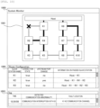
- a display screen 1000 of the display device 900 includes a system status display window 1001, a communication path window 1002, and a log monitoring window 1003.
- These windows are an example of a display area, and may be displayed in another mode.
- the system status display window 1001 displays a network configuration of the distributed control system 01 and a fault state of the communication slave station 012 and the communication channel.
- the system status display window 1001 is used by a user to intuitively recognize a fault location and a communication path of the distributed control system 01.
- the communication path window 1002 has a function of displaying a connection state of each communication slave station 012, whether the upstream port is changed, communication path information, and the like. Further, the communication path window 1002 is used by the user to analyze the communication slave station 012 affected by a fault occurring in the distributed control system 01 by displaying the communication path of each communication slave station 012.
- the log monitoring window 1003 has a function of displaying an execution time when communication path generation is executed, a communication abnormality detected by the distributed control system 01 as an execution reason, and an identified fault location.
- the distributed control system 01 can inform the user of the failure location, and the downtime of the distributed control system 01 can be reduced and the maintenance efficiency can be improved.
- FIG. 11 shows an application example of each example.
- a server device 9000 can manage a plurality of distributed control systems 01.
- the server device 9000 is connected to a network 9001 and the display device 900.
- the display device 900 inputs various instructions to the server device 9000 and outputs a processing result of the server device 9000.
- the output includes the display example in Example 3.
- the server device 9000 can be implemented by a computer, and can be referred to as a cloud system.
- the server device 9000 and the display device 900 may be implemented by one device.
- the server device 9000 is connected to a plurality of distributed control systems 01 via the network 9001 such as the Internet. As a result, the server device 9000 can receive a communication path created by each distributed control system 01. At least a part of the communication master station 011 in Example 1 may be executed by the server device 9000. In particular, the server device 9000 can create a communication path.
- the application example has been described above.
- a part or all of the configurations, functions, processing units, processing methods, and the like described above may be implemented by hardware by, for example, designing with an integrated circuit.
- the above configurations, functions, and the like may be implemented by software by a processor interpreting and executing a program for implementing each function.
- Information such as a program, a table, and a file for implementing each function can be stored in a recording device such as a memory, a hard disk, and a solid state drive (SSD), or in a recording medium such as an IC card, an SD card, and a DVD.
- the communication channels are considered to be necessary for explanation, and all the communication channels are not necessarily shown on a product to which the distributed control system 01 is applied.
- the communication path of the distributed control system 01 and the bypass path at the time of occurrence of a fault can be generated by the same procedure, and the fault location can be identified.
Landscapes
- Engineering & Computer Science (AREA)
- Computer Networks & Wireless Communication (AREA)
- Signal Processing (AREA)
- Data Exchanges In Wide-Area Networks (AREA)
- Small-Scale Networks (AREA)
Abstract
Description
- The present invention relates to a technique for generating a communication path that bypasses a failure such as a fault occurring in a network. The failure of the invention includes various abnormalities in communication such as a fault.
- At present, various communication techniques using a network are used. As an application example of the communication technique, an industrial apparatus is exemplified. In an industrial apparatus such as a biochemical and immune analyzer, an electronic system including an analog transmission path from a plurality of control boards centrally managed to a control device such as a sensor or a motor mounted on the apparatus is generally used.
- In recent years, in order to improve efficiency in design, manufacture, and maintenance of the apparatus, a distributed control system has been applied to reduce an amount of analog transmission paths and improve control performance of the apparatus by modularization and distributed arrangement of the control boards. In a distributed system including such a distributed control system, in order to reduce downtime of the apparatus (distributed control devices and distributed devices) constituting the distributed system, a redundant network including a plurality of communication paths may be used so that control communication can be continued even when a part of the apparatus fails. In such a redundant network, a plurality of communication paths can be provided between boards connected to the network. Therefore, when an appropriate communication path is not generated, an erroneous operation is caused. In addition, when a problem such as a fault occurs, it is necessary to generate a bypass path that can bypass a fault location to continue communication by using remaining redundant paths and identify a fault location to quickly perform repair.
- As means for solving these problems, there is generally known a technique in which, when a fault occurs in a redundant network, a communication master station generates a bypass path based on information on a network configuration and scans whether the communication master station can communicate with each communication slave station via the bypass path to identify a fault location, and for example, PTL 1 is proposed. In PTL 1, when a communication failure occurs, among communication paths from an aggregation device to a terminal device that becomes incommunicable, a relay device that is communicable and closest to the terminal device is identified as a target device, the aggregation device generates a bypass path to the target device based on network configuration information and identifies a location between a relay device closest to the target device among relay devices that are communicable through the bypass path and the target device as a fault location.
- PTL 1:
JP2021-52311A - However, in the technique described in PTL 1, the relay device is a device having a routing function of a router or the like, and in a protocol of a general routing function, the relay device needs to store path information to another relay device. Therefore, it is difficult to ensure a real-time property of the control communication due to the compression of a communication band, and the relay device has to prepare a storage capacity corresponding to a scale of the distributed system such as the distributed control system. Therefore, an object of the invention is to create a communication path in a distributed system with a simpler configuration.
- In order to solve the above problem, the invention provides a distributed system including a plurality of a distributed devices such as a communication master station and a plurality of communication slave stations, in which a communication port with an upstream side is dynamically updated according to a traffic volume of a communication path through which a routing packet is communicated, and based on this, a communication path is created.
- An example of a more specific configuration is a distributed system including:
- a communication master station; and
- a plurality of communication slave stations connected to the communication master station in a downstream direction of communication, in which
- the communication master station and each of the plurality of communication slave stations are connected to each other via a communication channel,
- the plurality of communication slave stations respectively include a plurality of communication ports for performing communication,
- any one of the plurality of communication ports is stored in advance as an upstream port for communication in an upstream direction,
- a routing packet is transmitted from the communication master station to each of the plurality of communication slave stations,
- a first traffic volume indicating a traffic volume of the routing packet from the communication master station is specified in each of the plurality of communication slave stations,
- the first traffic volume and a second traffic volume specified before the specification are compared to determine whether a predetermined condition is satisfied,
- a first communication port that has received the routing packet is specified in each of the plurality of communication slave stations,
- in each of the plurality of communication slave stations, the first communication port is updated as the upstream port when the predetermined condition is satisfied, and
- the communication master station creates a communication path from the communication master station in the distributed system by combining the upstream port in each of the plurality of communication slave stations and the communication channel connected to the upstream port. The invention also includes a method for creating a communication path in the distributed system.
- According to the invention, it is possible to create a communication path in a distributed system with a simpler configuration. Problems, configurations, and effects other than those described above will become apparent from the following description of embodiments and examples.
-
- [
FIG. 1] FIG. 1 shows a configuration example of a distributed control system according to an embodiment of the invention. - [
FIG. 2] FIG. 2 shows a state in which a routing packet of a distributed control system in Example 1 is transferred. - [
FIG. 3] FIG. 3 is a flowchart showing processing of comparing routing packets of a communication slave station in Example 1. - [
FIG. 4] FIG. 4 is a flowchart showing processing of selecting an upstream port of the communication slave station in Example 1. - [
FIG. 5] FIG. 5 shows transfer of an upstream port notification of the distributed control system in Example 1. - [
FIG. 6] FIG. 6 shows transfer of a routing packet in a case where a communication slave station fails in Example 2. - [
FIG. 7] FIG. 7 shows transfer of an upstream port notification in the case where the communication slave station fails in Example 2. - [
FIG. 8] FIG. 8 is a flowchart showing processing of identifying a fault location of a communication master station in Example 2. - [
FIG. 9] FIG. 9 shows a configuration example of a distributed control system in Example 3. - [
FIG. 10] FIG. 10 shows a display example in a display device in Example 3. - [
FIG. 11] FIG. 11 shows an application example of each example. - Hereinafter, an embodiment of the invention will be described. In the present embodiment, a distributed control system is used as an example of a distributed control system to control a control target including itself.
FIG. 1 shows a configuration example of adistributed control system 01 according to the present embodiment. InFIG. 1 , thedistributed control system 01 includes acommunication master station 011 and a plurality ofcommunication slave stations 012. Here, thecommunication master station 011 and thecommunication slave station 012 correspond to a distributed device of the invention. In addition, a direction toward an upper part of the drawing, that is, a direction of communication toward thecommunication master station 011 is defined as an upstream direction. A direction opposite to the upstream direction is defined as a downstream direction. - In the present embodiment, in the
distributed control system 01 including thecommunication master station 011 and the plurality ofcommunication slave stations 012, an upstream port which is a communication port with an upstream side is dynamically updated according to a traffic volume of a communication path through which a routing packet is communicated. Based on this, a communication path is created. An example of a more specific configuration is thedistributed control system 01 including: - the
communication master station 011; and - the plurality of
communication slave stations 012 connected to thecommunication master station 011 in a downstream direction of communication, in which - the
communication master station 011 and each of the plurality ofcommunication slave stations 012 are connected to each other via a communication channel (normal communication channel 0130, reducedcommunication channel 0131, and the like), - the plurality of
communication slave stations 012 respectively include a plurality ofcommunication ports 0120 for performing communication, - any one of the plurality of
communication ports 0120 is stored in advance as an upstream port, - a routing packet is transmitted from the
communication master station 011 to each of the plurality ofcommunication slave stations 012, - a first traffic volume indicating a traffic volume of the routing packet from the
communication master station 011 is specified in each of the plurality ofcommunication slave stations 012, - the first traffic volume and a second traffic volume specified before the specification are compared to determine whether a predetermined condition is satisfied,
- a first communication port that has received the routing packet is specified in each of the plurality of
communication slave stations 012, - in each of the plurality of
communication slave stations 012, the first communication port is updated as the upstream port when the predetermined condition is satisfied, and - the
communication master station 011 creates a communication path from thecommunication master station 011 in the distributedcontrol system 01 by combining the upstream port in each of the plurality ofcommunication slave stations 012 and the communication channel connected to the upstream port. - The description of the present embodiment is finished in the above, and examples showing more specific configurations and processing contents will be described below.
- As shown in
FIG. 1 , the distributedcontrol system 01 according to this example includes thecommunication master station 011 and the plurality ofcommunication slave stations 012. Thecommunication master station 011 forms a network connected to the plurality ofcommunication slave stations 012 via communication channels (thenormal communication channel 0130, the reducedcommunication channel 0131, and the like), and transmits a control command of the distributedcontrol system 01 to each of the communication slave stations. Thecommunication slave station 012 is connected to thecommunication master station 011 and anothercommunication slave station 012 via the network, and transmits input information from a control device to thecommunication master station 011. - Next, a configuration of each device will be described. The
communication slave station 012 includes the plurality ofcommunication ports 0120. Among them, thecommunication port 0120 used for transmission of its own input information and transfer of the input information from the control device of anothercommunication slave station 012 is defined as an upstream port. Thecommunication port 0120 used for transfer of the control command from thecommunication master station 011 to anothercommunication slave station 012 is defined as a downstream port. - The
communication master station 011 includes acommunication port 0110, an upstreamport storage unit 0111, a communicationpath storage unit 0112, a faultlocation identification unit 0113, and a communicationpath creation unit 0114. The upstreamport storage unit 0111 stores an upstream port of thecommunication slave station 012 itself. The communicationpath storage unit 0112 stores the created communication path. The faultlocation identification unit 0113 identifies a fault location. The communicationpath creation unit 0114 creates a communication path according to a traffic volume of a routing packet. - The distributed
control system 01 further includes thenormal communication channel 0130 and the reducedcommunication channel 0131. Thenormal communication channel 0130 connects thecommunication port 0110 and thecommunication port 0120 or connects thecommunication ports 0120 so that a communication path normally used by eachcommunication slave station 012 and thecommunication master station 011 has the minimum number of times of passage through thecommunication slave station 012. The reducedcommunication channel 0131 connects thecommunication ports 0120. In the connection, for eachcommunication slave station 012, when one of anothercommunication slave station 012 or thenormal communication channel 0130 fails, a communication path used for communication with thecommunication master station 011 includes a combination of communication channels having the number of times of passage through thecommunication slave station 012 equal to or less than the number of times of passage through thecommunication slave station 012 and being communicable within a predetermined communication delay time. - Next, a method for creating a communication path in the distributed
control system 01 will be described. First, the communicationpath creation unit 0114 of thecommunication master station 011 transmits arouting packet 02 to thecommunication slave station 012 via the communication channel connected to thecommunication master station 011 itself. Here, a transmission timing of therouting packet 02 includes a time when the distributedcontrol system 01 or thecommunication master station 011 is started up, a time when a failure occurs in the distributedcontrol system 01, a predetermined period, or a periodic timing.FIG. 2 shows a state in which therouting packet 02 is transferred in the distributedcontrol system 01 in this example. InFIG. 2 , therouting packet 02 accumulates the number of times of passage through the communication channel. Therefore, therouting packet 02 is transferred via thecommunication slave station 012, and eachcommunication slave station 012 receives therouting packet 02. Thecommunication slave station 012 that has received the routing packet adds 1 to the number of times of passage through the communication channel included in therouting packet 02 to update therouting packet 02. In this way, eachcommunication slave station 012 counts up the number of times of passage of therouting packet 02 and records the number of times of passage in therouting packet 02. - In this example, the number of times of passage through the communication channel is used, but the traffic volume through a passing path may be used. As the traffic volume, any one of the number of times of passage of the
routing packet 02 through thecommunication slave station 012 from thecommunication master station 011, a time it takes for therouting packet 02 to pass from thecommunication master station 011, and a physical length that therouting packet 02 passes from thecommunication master station 011 is used. More preferably, it is desirable to use the number of times of passage through the communication channel and/or the number of times of passage through thecommunication slave station 012 described above. For example, a number obtained by adding the number of times of passage through the communication channel and the number of times of passage through thecommunication slave station 012 may be used. - Here, in this example, when the number of times of passage through the communication channel satisfies a predetermined condition, a passing path is dynamically created and updated. More specifically, when the number of times of passage stored in each
communication slave station 012 is smaller than the specified number of times of passage, a passing path is created. Hereinafter, a comparison of the number of times of passage will be described.FIG. 3 is a flowchart showing processing of comparing therouting packets 02 of thecommunication slave station 012 according to this example. The flowchart is executed when thecommunication slave station 012 updates, for example, receives therouting packet 02. In a case where a processing subject of the flowchart is described as thecommunication slave station 012, eachcommunication slave station 012 constituting the distributedcontrol system 01 is the processing subject unless otherwise specified. The same applies to the other flowcharts. - First, in step S30, the
communication slave station 012 determines whether thecommunication slave station 012 itself stores aprevious routing packet 02. As a result, if the determination is positive (YES), the processing proceeds to step S31. If the determination is negative (NO), the processing proceeds to step S32. - In step S31, the
communication slave station 012 determines whether the number of times of passage of the updatedrouting packet 02 through the communication channel is smaller than the number of times of passage of therouting packet 02 through the communication channel stored in thecommunication slave station 012 itself. As a result, if the determination is positive (YES), the processing proceeds to step S32. If the determination is negative (NO), the processing ends and returns to a start state. In this step, a comparison is performed between the number of times of passage of the updatedrouting packet 02 through the communication channel, which is an example of a first traffic volume, and the number of times of passage of the storedrouting packet 02 through the communication channel, which is an example of a second traffic volume specified before the specification. - In step S32, the
communication slave station 012 specifies the updatedrouting packet 02 and thecommunication port 0120 that has received therouting packet 02. It is desirable that thecommunication slave station 012 stores specified contents and transfers the specified contents from the remainingcommunication ports 0120 included in thecommunication slave station 012 itself other than thecommunication port 0120 that has received therouting packet 02. In this way, the processing ends and returns to the start state. - The
routing packet 02 received or stored (updated) last by thecommunication slave station 012 has the smallest number of times of passage through the communication channel among the number of times of passage of theprevious routing packet 02 in thecommunication slave station 012. Therefore, the number of times of passage of therouting packet 02 to be compared in Step S31 may be the number of times of passage of only therouting packet 02 stored last by thecommunication slave station 012. In this example, thecommunication slave station 012 is described as storing theprevious routing packet 02, but may also store in advance and use the number of times of passage thereof. The same applies to the following description. - In addition, when storing the
routing packet 02 and thecommunication port 0120 that has received therouting packet 02 in step S33, thecommunication slave station 012 may delete theprevious routing packet 02 and theprevious communication port 0120. Further, thecommunication slave station 012 may have a storage capacity capable of storing one set of therouting packet 02 and thecommunication port 0120. Thecommunication slave station 012 transfers therouting packet 02 by increasing the number of times of passage of therouting packet 02 through the communication channel, and thus therouting packet 02 is eventually no longer transferred in the distributedcontrol system 01. - In this example, the upstream port is selected from the
communication port 0120 and updated according to the comparison result ofFIG. 3 . The upstream port constitutes a communication path to be created in this example.FIG. 4 is a flowchart showing processing of selecting an upstream port of thecommunication slave station 012 according to this example. The processing is preferably performed in parallel with the processing of the flowchart shown inFIG. 3 , but may be performed separately. - In step S40 of
FIG. 4 , thecommunication slave station 012 keeps the processing on standby until therouting packet 02 is newly stored or received. That is, thecommunication slave station 012 proceeds to step S32 inFIG. 3 , and if therouting packet 02 is newly stored or received (YES), the processing proceeds to step S41. If therouting packet 02 is not stored or received (NO), step S40 is continued. - In step S41, the
communication slave station 012 waits for a predetermined communication completion waiting time until the transfer of therouting packet 02 in the distributedcontrol system 01 is completed. After waiting, in step S42, thecommunication slave station 012 selects the communication port 0120 (a first communication port) last stored or received by thecommunication slave station 012 itself as the upstream port. - At this time, when another communication port 0120 (a second communication port) is stored as the upstream port in the past, the
communication slave station 012 updates thecommunication port 0120 as the communication port selected in this step. - In step S43, the
communication slave station 012 transmits anupstream port notification 050 including upstream port information on the upstream port selected and updated in step S42 from the selected upstream port to an upstream side. In step S44, thecommunication slave station 012 deletes therouting packet 02 stored therein and thecommunication port 0120 that has received therouting packet 02. In this way, the processing of the flowchart ends and returns to the start state. - Here, transmission and reception (communication) of the
upstream port notification 050 transmitted in step S43 in the distributedcontrol system 01 will be described.FIG. 5 shows transfer of theupstream port notification 050 of the distributedcontrol system 01 in this example. InFIG. 5 , theupstream port notification 050 is transferred from thecommunication slave station 012 as a transmission source to thecommunication master station 011 by anothercommunication slave station 012. That is, theupstream port notification 050 is transferred in the upstream direction. InFIG. 5 , thecommunication slave station 012 transmits theupstream port notification 050 from anupstream port 051 thereof. When thecommunication slave station 012 receives theupstream port notification 050 from anothercommunication slave station 012, the processing shown inFIG. 4 ends. When thecommunication slave station 012 returns to the state of waiting for storage of thenew routing packet 02 in step S40, thecommunication slave station 012 transfers the receivedupstream port notification 050. Otherwise, thecommunication slave station 012 holds theupstream port notification 050, and transfers the receivedupstream port notification 050 after the processing inFIG. 4 ends. - When performing the transfer, the
communication slave station 012 selects, as adownstream port 052, itsown communication port 0120 that has received theupstream port notification 050. The communicationpath creation unit 0114 of thecommunication master station 011 stores the receivedupstream port notification 050 of eachcommunication slave station 012 in the upstreamport storage unit 0111. Further, the communicationpath creation unit 0114 of thecommunication master station 011 creates a communication path with thecommunication slave station 012 by combining the communication channels to which the upstream ports are connected based on the upstream port information indicated by the storedupstream port notification 050. The communicationpath creation unit 0114 stores the communication path in the communicationpath storage unit 0112. - According to this example, it is possible to prevent repeated communication between the
communication master station 011 and eachcommunication slave station 012 for creating a communication path between thecommunication master station 011 and eachcommunication slave station 012 in the distributedcontrol system 01. The communication path between thecommunication master station 011 and eachcommunication slave station 012 in the distributedcontrol system 01 includes the communication channel through which therouting packet 02 is actually transferred. Therefore, for example, even when a communication abnormality due to an initial failure or the like occurs in the distributedcontrol system 01, the communication path includes a communication channel that avoids the failure. - Next, Example 2 shows processing when a failure occurs in the distributed
control system 01.FIG. 6 shows transfer of therouting packet 02 in a case where thecommunication slave station 012 fails in Example 2. InFIG. 6 , K1 of thecommunication slave station 012 of the distributedcontrol system 01 fails. The failed K1 of thecommunication slave station 012 cannot transfer therouting packet 02. Therefore, any ofrouting packets 02 shown inFIG. 2 is not transferred. Therefore, inFIG. 6 , therouting packet 02 passing through K6 of thecommunication slave station 012 is transferred to K2 to K5. -
FIG. 7 shows transfer of theupstream port notification 050 in the case where thecommunication slave station 012 fails in this example. By using theupstream port notification 050, the communicationpath creation unit 0114 creates a communication path from K2 to K5 of thecommunication slave station 012 using a bypass path including the reducedcommunication channel 0131 as the communication path. For example, a communication path of K3 of thecommunication slave station 012 is a bypass path from thecommunication master station 011 via K6, K7, K8, and K5. Here, the creation of the bypass path that avoids the failure in this manner leads to identification of a failure location. - The identification of the failure location in this example will be described.
-
FIG. 8 is a flowchart showing processing of identifying a fault location of thecommunication master station 011 in this example. First, thecommunication master station 011 waits until the newupstream port notification 050 is received from thecommunication slave station 012. In step S80, thecommunication master station 011 determines whether theupstream port notification 050 is received from thecommunication slave station 012, that is, whether theupstream port notification 050 arrives. As a result, if arrived (YES), the processing proceeds to step S81. If not arrived (NO), step S80 is continued. - In step S81, the
communication master station 011 waits until a predetermined time until the reception of theupstream port notification 050 from thecommunication slave station 012 is completed elapses. In step S82, the faultlocation identification unit 0113 determines whether theupstream port notification 050 arrives at thecommunication master station 011 from eachcommunication slave station 012. As a result, if the determination is positive (YES), the processing proceeds to step S83. If the determination is negative (NO), the processing proceeds to step S84. - In step S84, the fault
location identification unit 0113 identifies the fault location as thecommunication slave station 012 from which theupstream port notification 050 does not arrive. The processing then ends and returns to the start state. In step S83, the faultlocation identification unit 0113 determines whether there is a change in the upstream port based on the notified upstream port notification. As a result, if the determination is positive (YES), the processing proceeds to step S85. If the determination is negative (NO), the processing proceeds to step S86. - In step S85, the fault
location identification unit 0113 identifies the fault location as a communication channel closest to thecommunication master station 011 in a previous communication path among communication channels that are no longer used for the communication path. The processing then ends and returns to the start state. In step S86, the faultlocation identification unit 0113 determines that there is no fault location, and then the processing ends and returns to the start state. As described above, when a communication failure occurs in the distributedcontrol system 01, in a case where the faultlocation identification unit 0113 determines that there is no fault location, it can be estimated that a temporary communication abnormality occurs. In this example, since thecommunication master station 011 does not receive the notification from the K1 of thecommunication slave station 012, the determination in step S82 is negative (NO), and thecommunication master station 011 can identify that the K1 of thecommunication slave station 012 without the notification fails. That is, in steps S84 to S85, a cause of the communication failure that occurs in the distributedcontrol system 01 is identified. - As described above, according to this example, by performing the processing described in Example 1 in the same manner, information in each
communication slave station 012 indicating whether the communication with thecommunication master station 011 is possible, and which communication channel is used when the communication is possible is aggregated in thecommunication master station 011. Therefore, it is possible to identify a fault location, and it is possible to generate a bypass path to thecommunication slave station 012 in the distributedcontrol system 01 in which a fault occurs. In addition, an effect of applying the distributedcontrol system 01 is the same as that of Example 1. - Next, in Example 3, a display function is added to Example 1 and Example 2.
FIG. 9 shows a configuration example of the distributedcontrol system 01 according to this example.FIG. 9 is an example showing a state after theupstream port 051 is changed when thenormal communication channel 0130 between K1 and K2 of thecommunication slave station 012 fails. Here, for the K2 of thecommunication slave station 012, a communication port connected to K4 via the reducedcommunication channel 0131 is selected as theupstream port 051. Adisplay device 900 is connected to thecommunication master station 011 and acquires communication path information of the distributedcontrol system 01 from thecommunication master station 011. Thedisplay device 900 can be implemented by a computer such as a PC or a tablet. Thedisplay device 900 may be provided with a control function of controlling the distributedcontrol system 01. Next, display contents in thedisplay device 900 will be described. -
FIG. 10 shows a display example in thedisplay device 900 in this example. InFIG. 10 , adisplay screen 1000 of thedisplay device 900 includes a systemstatus display window 1001, acommunication path window 1002, and alog monitoring window 1003. These windows are an example of a display area, and may be displayed in another mode. Among these windows, the systemstatus display window 1001 displays a network configuration of the distributedcontrol system 01 and a fault state of thecommunication slave station 012 and the communication channel. The systemstatus display window 1001 is used by a user to intuitively recognize a fault location and a communication path of the distributedcontrol system 01. - The
communication path window 1002 has a function of displaying a connection state of eachcommunication slave station 012, whether the upstream port is changed, communication path information, and the like. Further, thecommunication path window 1002 is used by the user to analyze thecommunication slave station 012 affected by a fault occurring in the distributedcontrol system 01 by displaying the communication path of eachcommunication slave station 012. Thelog monitoring window 1003 has a function of displaying an execution time when communication path generation is executed, a communication abnormality detected by the distributedcontrol system 01 as an execution reason, and an identified fault location. - According to this example described above, the distributed
control system 01 can inform the user of the failure location, and the downtime of the distributedcontrol system 01 can be reduced and the maintenance efficiency can be improved. - The invention is not limited to the examples described above and includes various modifications and application examples. Here, an application example of the invention will be described.
FIG. 11 shows an application example of each example. In this application example, aserver device 9000 can manage a plurality of distributedcontrol systems 01. Theserver device 9000 is connected to anetwork 9001 and thedisplay device 900. Thedisplay device 900 inputs various instructions to theserver device 9000 and outputs a processing result of theserver device 9000. The output includes the display example in Example 3. Theserver device 9000 can be implemented by a computer, and can be referred to as a cloud system. Theserver device 9000 and thedisplay device 900 may be implemented by one device. - The
server device 9000 is connected to a plurality of distributedcontrol systems 01 via thenetwork 9001 such as the Internet. As a result, theserver device 9000 can receive a communication path created by each distributedcontrol system 01. At least a part of thecommunication master station 011 in Example 1 may be executed by theserver device 9000. In particular, theserver device 9000 can create a communication path. The application example has been described above. - The above examples have been described in detail to facilitate understanding of the invention, and the invention is not necessarily limited to those including all the configurations described above. A part of a configuration of a certain example can be replaced with a configuration of another example, and the configuration of another example can be added to the configuration of a certain example. A part of a configuration of each example may be added to, deleted from, or replaced with another configuration.
- A part or all of the configurations, functions, processing units, processing methods, and the like described above may be implemented by hardware by, for example, designing with an integrated circuit. In addition, the above configurations, functions, and the like may be implemented by software by a processor interpreting and executing a program for implementing each function. Information such as a program, a table, and a file for implementing each function can be stored in a recording device such as a memory, a hard disk, and a solid state drive (SSD), or in a recording medium such as an IC card, an SD card, and a DVD. In addition, the communication channels are considered to be necessary for explanation, and all the communication channels are not necessarily shown on a product to which the distributed
control system 01 is applied. - In each of the above examples, the communication path of the distributed
control system 01 and the bypass path at the time of occurrence of a fault can be generated by the same procedure, and the fault location can be identified. In addition, it is possible to prevent periodic communication for creating a communication path. Therefore, since a communication band is not compressed, a real-time property of control communication can be ensured. Since thecommunication slave station 012 does not need to store the communication path information of the communication slave stations other than thecommunication slave station 012 itself, the storage capacity corresponding to a scale of the distributedcontrol system 01 can be reduced. Further, in each example, it is not necessary to perform regular communication in order to create a communication path. -
- 01: distributed control system
- 011: communication master station
- 0110: communication port of communication master station
- 0111: upstream port storage unit
- 0112: communication path storage unit
- 0113: fault location identification unit
- 012: communication slave station
- 0120: communication port of communication slave station
- 0130: normal communication channel
- 0131: reduced communication channel
- 02: routing packet
- 050: upstream port notification
- 051: upstream port
- 052: downstream port
- 060: fault of communication slave station
- 900: display device
- 901: fault of communication channel
- 1000: display screen
- 1001: system status display window
- 1002: communication path window
- 1003: log monitoring window
Claims (20)
- A distributed system comprising:a communication master station; anda plurality of communication slave stations connected to the communication master station in a downstream direction of communication, whereinthe communication master station and each of the plurality of communication slave stations are connected to each other via a communication channel,the plurality of communication slave stations respectively include a plurality of communication ports for performing communication,any one of the plurality of communication ports is stored in advance as an upstream port for communication in an upstream direction,a routing packet is transmitted from the communication master station to each of the plurality of communication slave stations,a first traffic volume indicating a traffic volume of the routing packet from the communication master station is specified in each of the plurality of communication slave stations,the first traffic volume and a second traffic volume specified before the specification are compared to determine whether a predetermined condition is satisfied,a first communication port that has received the routing packet is specified in each of the plurality of communication slave stations,in each of the plurality of communication slave stations, the first communication port is updated as the upstream port when the predetermined condition is satisfied, andthe communication master station creates a communication path from the communication master station in the distributed system by combining the upstream port in each of the plurality of communication slave stations and the communication channel connected to the upstream port.
- The distributed system according to claim 1, wherein
the predetermined condition is that the first traffic volume is small or that the second traffic volume is not specified. - The distributed system according to claim 1, wherein
any one of the number of times of passage of the routing packet through the communication channel, the number of times of passage of the routing packet through the communication slave station from the communication master station, a time it takes for the routing packet to pass from the communication master station, and a physical length that the routing packet passes from the communication master station is used as the traffic volume. - The distributed system according to claim 1, whereinin each of the plurality of communication slave stations, when the upstream port is updated to the first communication port, an upstream port notification indicating that the updated first communication port is selected as the upstream port is transmitted to the communication master station, andthe communication master station generates the communication path using the upstream port notification.
- The distributed system according to claim 4, wherein
when a communication failure occurs in the distributed system, the communication master station transmits the routing packet. - The distributed system according to claim 5, whereinin a case where the communication failure occurs in the distributed system,when the upstream port notification is not issued for a predetermined period of time, the communication master station determines that a cause of the communication failure occurs in the corresponding one of the communication slave stations.
- The distributed system according to claim 6, wherein
when the upstream port notification is received from each of the plurality of communication slave stations, and the communication path is changed, the communication master station determines that the cause of the communication failure occurs in a most upstream communication channel in the communication path before the change. - The distributed system according to claim 6 or 7, wherein
the communication master station creates a bypass path for avoiding the cause of the communication failure as the communication path. - The distributed system according to claim 4, wherein
in each of the plurality of communication slave stations, an upstream port notification transmitted from a downstream direction of the communication slave station itself is transferred in an upstream direction. - The distributed system according to claim 1, wherein
the communication master station periodically transmits the routing packet. - A method for creating a communication path in a distributed system including a communication master station and a plurality of communication slave stations connected to the communication master station in a downstream direction of communication, whereinthe communication master station and each of the plurality of communication slave stations are connected to each other via a communication channel,the plurality of communication slave stations respectively include a plurality of communication ports for performing communication,any one of the plurality of communication ports is stored in advance as an upstream port for communication in an upstream direction,a routing packet is transmitted from the communication master station to each of the plurality of communication slave stations,a first traffic volume indicating a traffic volume of the routing packet from the communication master station is specified in each of the plurality of communication slave stations,the first traffic volume and a second traffic volume specified before the specification are compared to determine whether a predetermined condition is satisfied,a first communication port that has received the routing packet is specified in each of the plurality of communication slave stations,in each of the plurality of communication slave stations, the first communication port is updated as the upstream port when the predetermined condition is satisfied, andthe communication master station creates a communication path from the communication master station in the distributed system by combining the upstream port in each of the plurality of communication slave stations and the communication channel connected to the upstream port.
- The method for creating a communication path in the distributed system according to claim 11, wherein
the predetermined condition is that the first traffic volume is small or that the second traffic volume is not specified. - The method for creating a communication path in the distributed system according to claim 11, wherein
any one of the number of times of passage of the routing packet through the communication channel, the number of times of passage of the routing packet through the communication slave station from the communication master station, a time it takes for the routing packet to pass from the communication master station, and a physical length that the routing packet passes from the communication master station is used as the traffic volume. - The method for creating a communication path in the distributed system according to claim 11, whereinin each of the plurality of communication slave stations, when the upstream port is updated to the first communication port, an upstream port notification indicating that the updated first communication port is selected as the upstream port is transmitted to the communication master station, andthe communication master station generates the communication path using the upstream port notification.
- The method for creating a communication path in the distributed system according to claim 14, wherein
when a communication failure occurs in the distributed system, the communication master station transmits the routing packet. - The method for creating a communication path in the distributed system according to claim 15, whereinin a case where the communication failure occurs in the distributed system,when the upstream port notification is not issued for a predetermined period of time, the communication master station determines that a cause of the communication failure occurs in the corresponding one of the communication slave stations.
- The method for creating a communication path in the distributed system according to claim 16, wherein
when the upstream port notification is received from each of the plurality of communication slave stations, and the communication path is changed, the communication master station determines that the cause of the communication failure occurs in a most upstream communication channel in the communication path before the change. - The method for creating a communication path in the distributed system according to claim 16 or 17, wherein
the communication master station creates a bypass path for avoiding the cause of the communication failure as the communication path. - The method for creating a communication path in the distributed system according to claim 14, wherein
in each of the plurality of communication slave stations, an upstream port notification transmitted from a downstream direction of the communication slave station itself is transferred in an upstream direction. - The method for creating a communication path in the distributed system according to claim 11, wherein
the communication master station periodically transmits the routing packet.
Applications Claiming Priority (2)
| Application Number | Priority Date | Filing Date | Title |
|---|---|---|---|
| JP2022053854A JP7712888B2 (en) | 2022-03-29 | 2022-03-29 | Distributed system and method for creating communication paths in the distributed system |
| PCT/JP2023/004334 WO2023188860A1 (en) | 2022-03-29 | 2023-02-09 | Distributed system and method for creating communication path in distributed system |
Publications (2)
| Publication Number | Publication Date |
|---|---|
| EP4503557A1 true EP4503557A1 (en) | 2025-02-05 |
| EP4503557A4 EP4503557A4 (en) | 2026-02-25 |
Family
ID=88200945
Family Applications (1)
| Application Number | Title | Priority Date | Filing Date |
|---|---|---|---|
| EP23776829.6A Pending EP4503557A4 (en) | 2022-03-29 | 2023-02-09 | DISTRIBUTED SYSTEM AND METHOD FOR CREATING A COMMUNICATION PATH IN A DISTRIBUTED SYSTEM |
Country Status (5)
| Country | Link |
|---|---|
| US (1) | US20250175418A1 (en) |
| EP (1) | EP4503557A4 (en) |
| JP (1) | JP7712888B2 (en) |
| CN (1) | CN119137919A (en) |
| WO (1) | WO2023188860A1 (en) |
Families Citing this family (1)
| Publication number | Priority date | Publication date | Assignee | Title |
|---|---|---|---|---|
| WO2026163464A1 (en) * | 2025-02-03 | 2026-08-06 | 株式会社日立ハイテク | Distributed control system and distributed control method |
Family Cites Families (3)
| Publication number | Priority date | Publication date | Assignee | Title |
|---|---|---|---|---|
| JP4592800B2 (en) * | 2009-03-12 | 2010-12-08 | パナソニック株式会社 | Route selection device, route selection method, and program |
| WO2013042207A1 (en) | 2011-09-20 | 2013-03-28 | 富士通株式会社 | Node device and communication method |
| JP2015207797A (en) * | 2014-04-17 | 2015-11-19 | 日本電信電話株式会社 | Communication system and redundancy method |
-
2022
- 2022-03-29 JP JP2022053854A patent/JP7712888B2/en active Active
-
2023
- 2023-02-09 EP EP23776829.6A patent/EP4503557A4/en active Pending
- 2023-02-09 CN CN202380026341.3A patent/CN119137919A/en active Pending
- 2023-02-09 US US18/842,458 patent/US20250175418A1/en active Pending
- 2023-02-09 WO PCT/JP2023/004334 patent/WO2023188860A1/en not_active Ceased
Also Published As
| Publication number | Publication date |
|---|---|
| US20250175418A1 (en) | 2025-05-29 |
| EP4503557A4 (en) | 2026-02-25 |
| JP2023146599A (en) | 2023-10-12 |
| CN119137919A (en) | 2024-12-13 |
| JP7712888B2 (en) | 2025-07-24 |
| WO2023188860A1 (en) | 2023-10-05 |
Similar Documents
| Publication | Publication Date | Title |
|---|---|---|
| TWI621013B (en) | Systems for monitoring application servers | |
| US20110099273A1 (en) | Monitoring apparatus, monitoring method, and a computer-readable recording medium storing a monitoring program | |
| US9473418B2 (en) | Resource over-subscription | |
| US20200252262A1 (en) | Event-triggered distributed data collection in a distributed transaction monitoring system | |
| CN110928679A (en) | Resource allocation method and device | |
| CN110457176A (en) | Monitoring method, device, storage medium and electronic device for distributed system | |
| US11743108B1 (en) | Dynamic customization of network controller data path based on controller internal state awareness | |
| CN112214551A (en) | Data synchronization method, system, device, electronic equipment and storage medium | |
| CN117573409B (en) | A log recording method, device and storage medium for vehicle parts | |
| US20250175418A1 (en) | Distributed System and Method for Creating Communication Path in Distributed System | |
| CN108737163B (en) | A performance analysis method of SDN controller based on OpenFlow protocol | |
| CN106776206A (en) | The method of monitor process state, device and electronic equipment | |
| CN114124803B (en) | Device management method and device, electronic device and storage medium | |
| CN119668921A (en) | A method, device and storage medium for repairing a faulty node in a container orchestration system | |
| CN109219105B (en) | Route switching method and route switching system | |
| CN116723111B (en) | Service request processing method, system and electronic equipment | |
| US9575865B2 (en) | Information processing system and monitoring method | |
| US9787533B2 (en) | Obstruction determination device | |
| US20200133252A1 (en) | Systems and methods for monitoring performance of a building management system via log streams | |
| CN105337781A (en) | Network management system and method and network system | |
| CN116016209B (en) | A network automation method and apparatus | |
| CN114168405B (en) | Data monitoring method, device, terminal equipment and storage medium | |
| JP6775452B2 (en) | Monitoring system, program and monitoring method | |
| CN117555711A (en) | A virtual machine management method, device, cloud computing platform and medium | |
| CN116527483A (en) | Fault detection method and fault detection device |
Legal Events
| Date | Code | Title | Description |
|---|---|---|---|
| STAA | Information on the status of an ep patent application or granted ep patent |
Free format text: STATUS: UNKNOWN |
|
| STAA | Information on the status of an ep patent application or granted ep patent |
Free format text: STATUS: THE INTERNATIONAL PUBLICATION HAS BEEN MADE |
|
| PUAI | Public reference made under article 153(3) epc to a published international application that has entered the european phase |
Free format text: ORIGINAL CODE: 0009012 |
|
| STAA | Information on the status of an ep patent application or granted ep patent |
Free format text: STATUS: REQUEST FOR EXAMINATION WAS MADE |
|
| 17P | Request for examination filed |
Effective date: 20240821 |
|
| AK | Designated contracting states |
Kind code of ref document: A1 Designated state(s): AL AT BE BG CH CY CZ DE DK EE ES FI FR GB GR HR HU IE IS IT LI LT LU LV MC ME MK MT NL NO PL PT RO RS SE SI SK SM TR |
|
| DAV | Request for validation of the european patent (deleted) | ||
| DAX | Request for extension of the european patent (deleted) | ||
| REG | Reference to a national code |
Ref country code: DE Ref legal event code: R079 Free format text: PREVIOUS MAIN CLASS: H04L0045440000 Ipc: H04L0045000000 |
|
| A4 | Supplementary search report drawn up and despatched |
Effective date: 20260123 |
|
| RIC1 | Information provided on ipc code assigned before grant |
Ipc: H04L 45/00 20220101AFI20260119BHEP Ipc: H04L 45/02 20220101ALI20260119BHEP Ipc: H04L 45/44 20220101ALI20260119BHEP Ipc: H04L 45/28 20220101ALI20260119BHEP Ipc: H04L 45/122 20220101ALI20260119BHEP Ipc: H04L 41/0659 20220101ALI20260119BHEP Ipc: H04L 41/0677 20220101ALI20260119BHEP Ipc: H04L 43/0876 20220101ALI20260119BHEP Ipc: H04L 41/0686 20220101ALI20260119BHEP |