EP4503530A1 - Transmitter, method and program - Google Patents
Transmitter, method and program Download PDFInfo
- Publication number
- EP4503530A1 EP4503530A1 EP23779258.5A EP23779258A EP4503530A1 EP 4503530 A1 EP4503530 A1 EP 4503530A1 EP 23779258 A EP23779258 A EP 23779258A EP 4503530 A1 EP4503530 A1 EP 4503530A1
- Authority
- EP
- European Patent Office
- Prior art keywords
- receiver
- pilot signal
- distortion compensation
- linear distortion
- transmitter
- Prior art date
- Legal status (The legal status is an assumption and is not a legal conclusion. Google has not performed a legal analysis and makes no representation as to the accuracy of the status listed.)
- Pending
Links
Images


Classifications
-
- H—ELECTRICITY
- H04—ELECTRIC COMMUNICATION TECHNIQUE
- H04B—TRANSMISSION
- H04B1/00—Details of transmission systems, not covered by a single one of groups H04B3/00 - H04B13/00; Details of transmission systems not characterised by the medium used for transmission
- H04B1/02—Transmitters
- H04B1/04—Circuits
-
- H—ELECTRICITY
- H04—ELECTRIC COMMUNICATION TECHNIQUE
- H04B—TRANSMISSION
- H04B1/00—Details of transmission systems, not covered by a single one of groups H04B3/00 - H04B13/00; Details of transmission systems not characterised by the medium used for transmission
- H04B1/02—Transmitters
- H04B1/04—Circuits
- H04B1/0475—Circuits with means for limiting noise, interference or distortion
-
- H—ELECTRICITY
- H04—ELECTRIC COMMUNICATION TECHNIQUE
- H04B—TRANSMISSION
- H04B1/00—Details of transmission systems, not covered by a single one of groups H04B3/00 - H04B13/00; Details of transmission systems not characterised by the medium used for transmission
- H04B1/06—Receivers
- H04B1/10—Means associated with receiver for limiting or suppressing noise or interference
- H04B1/12—Neutralising, balancing, or compensation arrangements
- H04B1/123—Neutralising, balancing, or compensation arrangements using adaptive balancing or compensation means
-
- H—ELECTRICITY
- H04—ELECTRIC COMMUNICATION TECHNIQUE
- H04B—TRANSMISSION
- H04B17/00—Monitoring; Testing
- H04B17/20—Monitoring; Testing of receivers
- H04B17/21—Monitoring; Testing of receivers for calibration; for correcting measurements
-
- H—ELECTRICITY
- H04—ELECTRIC COMMUNICATION TECHNIQUE
- H04B—TRANSMISSION
- H04B3/00—Line transmission systems
- H04B3/02—Details
- H04B3/04—Control of transmission; Equalising
- H04B3/06—Control of transmission; Equalising by the transmitted signal
-
- H—ELECTRICITY
- H04—ELECTRIC COMMUNICATION TECHNIQUE
- H04L—TRANSMISSION OF DIGITAL INFORMATION, e.g. TELEGRAPHIC COMMUNICATION
- H04L25/00—Baseband systems
- H04L25/02—Details ; arrangements for supplying electrical power along data transmission lines
- H04L25/0202—Channel estimation
- H04L25/0224—Channel estimation using sounding signals
- H04L25/0226—Channel estimation using sounding signals sounding signals per se
-
- H—ELECTRICITY
- H04—ELECTRIC COMMUNICATION TECHNIQUE
- H04L—TRANSMISSION OF DIGITAL INFORMATION, e.g. TELEGRAPHIC COMMUNICATION
- H04L5/00—Arrangements affording multiple use of the transmission path
- H04L5/003—Arrangements for allocating sub-channels of the transmission path
- H04L5/0048—Allocation of pilot signals, i.e. of signals known to the receiver
Definitions
- the present invention relates to a transmitter, a method, and a program that are suitable for a configuration that performs non-linear distortion compensation on the receiving side.
- NPL1 compensation of non-linear distortion is performed on the receiving side, utilizing a neural network. Since all subcarriers transmit a pilot signal, a block pilot symbol is transmitted every frame before the data symbol, and compensation of the propagation path and compensation of non-linear distortion are performed at the same time by inputting the results of LS (Least Squares) estimation that uses the block pilot symbols to the neural network.
- LS Least Squares
- PTL1 Japanese Patent Laid-Open No. 2021-507605
- NPL1 K. Mei, J. Liu, X. Zhang, K. Cao, N. Rajatheva, and J. Wei, 'A Low Complexity Learning-Based Channel Estimation for OFDM Systems With Online Training', IEEE Transactions on Communications, vol. 69, no. 10, pp. 6722-6733, Oct. 2021
- a problem with PTL1 is that, in the case where non-constant envelopes are sent as pilot signals, all of the non-constant envelopes need to be disposed in independent resources in consideration of the influence of interference with other users, and resource utilization efficiency is poor. Also, a problem with NPL1 is that propagation path estimation and non-linear distortion estimation are performed at the same time, and block pilot symbols need to be sent at a similar frequency to the propagation path estimation, and thus transmission efficiency deteriorates significantly.
- an object of the present invention is to provide a technology that enables non-linear distortion compensation to be performed efficiently from the viewpoint of resource utilization efficiency, transmission efficiency and the like.
- the present invention is a transmitter paired with a receiver that performs non-linear distortion compensation by deep learning, configured to: separately generate a pilot signal for non-linear distortion compensation to be used by the receiver and a pilot signal for channel estimation to be used by the receiver; and transmit the generated pilot signals to the receiver.
- the receiver it is possible to enable the receiver to perform non-linear distortion compensation efficiently, by separately generating a pilot signal for non-linear distortion compensation and a pilot signal for channel estimation.
- FIG. 1 is a diagram showing the configuration of a communication system 100 according to one embodiment and steps S 1 to S3 of a procedure that is implemented in the configuration.
- the communication system 100 is part of a cellular communication system (mobile communication network) supporting 5G, for example, and includes a transmitter 10 serving as a base station device and a receiver 20 serving as a user terminal which is a mobile communication device such as a smartphone.
- a transmitter 10 serving as a base station device
- a receiver 20 serving as a user terminal which is a mobile communication device such as a smartphone.
- pilot signals are transmitted downstream as shown in FIG. 1 will be described as an example, but the present embodiment is applicable in exactly the same manner in the opposite case where pilot signals are transmitted upstream (the transmitter 10 (base station) in FIG. 1 is on the receiving side and the receiver 20 (user terminal) is on the transmitting side in relation to the pilot signals).
- the transmitter 10 and the receiver 20 in FIG. 1 are named according to the direction in which the pilot signals are transmitted/received, and the transmitter 10 in FIG. 1 may be a user terminal and the receiver 20 may be a base station device.
- the transmitter 10 in FIG. 1 may be a user terminal and the receiver 20 may be a base station device.
- steps S1 to S3 are shown as a procedure that is executed between the transmitter 10 and the receiver 20 in the wirelessly communicable state.
- steps S1 to S3 will be described.
- step S1 the transmitter 10 generates a frame containing a pilot signal and transmits this frame to the receiver 20.
- a pilot signal for channel estimation for transmission line estimation
- the pilot signal for non-linear distortion estimation are distinguished from each other, unlike the pilot signals of the comparative example, with the pilot signal for channel estimation being generated with higher frequency within frames, and the pilot signal for non-linear distortion estimation being generated with lower frequency within frames.
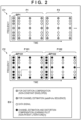
- FIG. 2 is a diagram showing a frame configuration C1 containing pilot signals that are generated in the present embodiment in comparison to a frame configuration C2 of the comparative example. Note that a legend field EX is provided in order to show the contents of these frame configurations C1 and C2.
- pilot signals for distortion compensation in chronologically-ordered OFDM (orthogonal frequency-division multiplexing) frames F1, F2, ...
- pilot signals for channel estimation in chronologically-ordered OFDM (orthogonal frequency-division multiplexing) frames F1, F2, ...
- pilot signals for distortion compensation in chronologically-ordered OFDM (orthogonal frequency-division multiplexing) frames F1, F2, ...
- pilot signals for channel estimation indicated by gray circles in the diagram
- FIG. 3 lists the attributes of the pilot signal for channel estimation and the pilot signal for non-linear distortion compensation in the frame configuration C1 of the present embodiment in tabular format.
- the ZC sequence which is an orthogonal sequence
- PTL1 user multiplexing
- a block pilot in an OFDM frame that is intermittently generated/transmitted only once every several frames can be constituted by all (or part) thereof in a sequence of non-constant envelopes.
- step S2 the receiver 20 receives the frame containing the pilot signal generated and transmitted by the transmitter 10 in step S 1, and performs channel estimation by LS estimation of the block pilot BP1 or the like, and learns non-linear distortion using a pilot signal for distortion compensation after channel equalization. That is, a trained compensator is obtained, by obtaining a channel estimation result at the time from the block pilot BP 1, obtaining a block pilot BP1 [channel equalized] that is channel-equalized using this channel estimation result, and learning non-linear distortion from this channel-equalized block pilot BP1 [channel equalized] .
- step S3 the receiver 20 further channel equalizes data signals of corresponding times (data signals shown by white circles in FIG.
- pilot signals for channel estimation are constituted as scattered pilots
- the processing content itself may be similar to the comparative example (NPL1), except that the data that is handled is a frame containing a pilot signal according to the present embodiment, and a distinction is made between pilot signals for channel estimation and pilot signals for distortion compensation.
- channel estimation and non-linear distortion compensation processing are separated, and different pilot signals are used for each, with channel estimation being implemented with higher frequency and non-linear distortion estimation being implemented with lower frequency.
- transmission frequency of the pilot signal for distortion compensation which has poor resource utilization efficiency and transmission efficiency can be reduced, and resource utilization efficiency and transmission efficiency in the case where distortion compensation processing on the receiving side is performed can be improved.
- FIG. 4 is a diagram showing an example of a configuration of a computer device 200 provided with a wireless communication function, and the transmitter 10 and the receiver 20 in the wireless communication system 100 can each be realized as a device having the configuration of the computer device 200.
- the computer device 200 includes a processor 201 constituted by a CPU (and GPU) and the like, a memory 202 serving as a temporary storage device that provides a work area to the processor 201, a storage 203 serving as a secondary storage device, a modulation/demodulation circuit 204, an antenna 205, and a bus BS that connects these devices in a manner that allows for communication of digital data therebetween.
- a processor 201 constituted by a CPU (and GPU) and the like
- a memory 202 serving as a temporary storage device that provides a work area to the processor 201
- a storage 203 serving as a secondary storage device
- a modulation/demodulation circuit 204 an antenna 205
- a bus BS that connects these devices in a manner that allows for communication of digital data therebetween.
- the processor 201 executes the respective processing (relating to digital processing) of the transmitter 10 and the receiver 20 in each of the embodiments described above, by executing a predetermined program stored in the storage 203 and loaded into the memory 202. That is, in the transmitter 10, the processor 201 executes the pilot signal generation and transmission processing of step S1 as a predetermined program. Also, in the receiver 20, the processor 201 executes the channel estimation and distortion learning by deep learning of steps S2 and S3 on signals as a predetermined program.
- the antenna 205 may be constituted to include a plurality of antennas, and may be capable of configuring a plurality of beam patterns by switching the antennas that are used.
- the modulation/demodulation circuit 204 modulates and demodulates wireless signals that are transmitted and received from the antenna 205.
- the communication system 100 of the present embodiment is able to improve resource utilization efficiency and transmission efficiency in the case of performing distortion compensation processing on the receiving side, and is thus able to contribute to infrastructure development of information and communication technologies. It is thereby possible to contribute to Goal 9 of the Sustainable Development Goals (SDGs) spearheaded by the United Nations, which is to "build resilient infrastructure, promote inclusive and sustainable industrialization, and foster innovation".
- SDGs Sustainable Development Goals
Landscapes
- Engineering & Computer Science (AREA)
- Signal Processing (AREA)
- Computer Networks & Wireless Communication (AREA)
- Physics & Mathematics (AREA)
- Electromagnetism (AREA)
- Power Engineering (AREA)
- Cable Transmission Systems, Equalization Of Radio And Reduction Of Echo (AREA)
- Transmitters (AREA)
Abstract
Description
- The present invention relates to a transmitter, a method, and a program that are suitable for a configuration that performs non-linear distortion compensation on the receiving side.
- Conventional technologies relating to non-linear distortion compensation of a power amplifier that is utilized in communication such as 5G (fifth generation mobile communication system) being performed on the receiving side are disclosed in PTL1 and NPL1.
- In PTL1, compensation of non-linear distortion is performed on the receiving side utilizing non-constant envelopes. This is conceivably because, in the case of performing compensation of non-linear distortion on the receiving side, sufficient compensation cannot be achieved when a signal having a large amplitude is generated, in the case where distortion is learned using a Zadoff-Chu sequence (ZC sequence) having a constant amplitude as is used in 5G.
- Also, in NPL1, compensation of non-linear distortion is performed on the receiving side, utilizing a neural network. Since all subcarriers transmit a pilot signal, a block pilot symbol is transmitted every frame before the data symbol, and compensation of the propagation path and compensation of non-linear distortion are performed at the same time by inputting the results of LS (Least Squares) estimation that uses the block pilot symbols to the neural network.
- PTL1:
Japanese Patent Laid-Open No. 2021-507605 - NPL1: K. Mei, J. Liu, X. Zhang, K. Cao, N. Rajatheva, and J. Wei, 'A Low Complexity Learning-Based Channel Estimation for OFDM Systems With Online Training', IEEE Transactions on Communications, vol. 69, no. 10, pp. 6722-6733, Oct. 2021
- However, conventional techniques for non-linear distortion compensation on the receiving side such as described above still have room for improvement in terms of efficiency.
- That is, a problem with PTL1 is that, in the case where non-constant envelopes are sent as pilot signals, all of the non-constant envelopes need to be disposed in independent resources in consideration of the influence of interference with other users, and resource utilization efficiency is poor. Also, a problem with NPL1 is that propagation path estimation and non-linear distortion estimation are performed at the same time, and block pilot symbols need to be sent at a similar frequency to the propagation path estimation, and thus transmission efficiency deteriorates significantly.
- In view of the above problems with the conventional technologies, an object of the present invention is to provide a technology that enables non-linear distortion compensation to be performed efficiently from the viewpoint of resource utilization efficiency, transmission efficiency and the like.
- In order to achieve the above mentioned object, the present invention is a transmitter paired with a receiver that performs non-linear distortion compensation by deep learning, configured to: separately generate a pilot signal for non-linear distortion compensation to be used by the receiver and a pilot signal for channel estimation to be used by the receiver; and transmit the generated pilot signals to the receiver.
- According to the present invention, it is possible to enable the receiver to perform non-linear distortion compensation efficiently, by separately generating a pilot signal for non-linear distortion compensation and a pilot signal for channel estimation.
- Other features and advantages of the present invention will be apparent from the following description taken in conjunction with the accompanying drawings. Note that the same reference numerals denote the same or like components throughout the accompanying drawings.
- The accompanying drawings, which are incorporated in and constitute a part of the specification, illustrate embodiments of the invention and, together with the description, serve to explain principles of the invention.
-
FIG. 1 is a diagram showing the configuration of a communication system according to one embodiment and a procedure that is implemented in the configuration. -
FIG. 2 is a diagram showing a frame configuration including pilot signals generated in the one embodiment in comparison to a comparative example. -
FIG. 3 is a diagram listing attributes of a pilot signal for channel estimation and a pilot signal for non-linear distortion compensation in the frame configuration of the present embodiment in tabular format. -
FIG. 4 is a diagram showing an example of the configuration of a computer device provided with a wireless communication function. - Hereinafter, embodiments will be described in detail with reference to the attached drawings. Note, the following embodiments are not intended to limit the scope of the claimed invention, and limitation is not made to an invention that requires a combination of all features described in the embodiments. Two or more of the multiple features described in the embodiments may be combined as appropriate. Furthermore, the same reference numerals are given to the same or similar configurations, and redundant description thereof is omitted.
-
FIG. 1 is a diagram showing the configuration of acommunication system 100 according to one embodiment and stepsS 1 to S3 of a procedure that is implemented in the configuration. Thecommunication system 100 is part of a cellular communication system (mobile communication network) supporting 5G, for example, and includes atransmitter 10 serving as a base station device and areceiver 20 serving as a user terminal which is a mobile communication device such as a smartphone. Note that, hereinafter, the case where pilot signals are transmitted downstream as shown inFIG. 1 will be described as an example, but the present embodiment is applicable in exactly the same manner in the opposite case where pilot signals are transmitted upstream (the transmitter 10 (base station) inFIG. 1 is on the receiving side and the receiver 20 (user terminal) is on the transmitting side in relation to the pilot signals). (In other words, thetransmitter 10 and thereceiver 20 inFIG. 1 are named according to the direction in which the pilot signals are transmitted/received, and thetransmitter 10 inFIG. 1 may be a user terminal and thereceiver 20 may be a base station device.) While there can be a plurality oftransmitters 10 andreceivers 20, an arbitrary one of each which is capable of wireless communication with the other devices is shown inFIG. 1 out of the plurality of devices that can exist, and steps S1 to S3 are shown as a procedure that is executed between thetransmitter 10 and thereceiver 20 in the wirelessly communicable state. Hereinafter, each of steps S1 to S3 will be described. - In step S1, the
transmitter 10 generates a frame containing a pilot signal and transmits this frame to thereceiver 20. In this generation of a pilot signal within a frame, as a technique that improves on the technique of NPL1 (hereinafter referred to as the "comparative example", etc., in contrast to the present embodiment), the pilot signal for channel estimation (for transmission line estimation) and the pilot signal for non-linear distortion estimation are distinguished from each other, unlike the pilot signals of the comparative example, with the pilot signal for channel estimation being generated with higher frequency within frames, and the pilot signal for non-linear distortion estimation being generated with lower frequency within frames. -
FIG. 2 is a diagram showing a frame configuration C1 containing pilot signals that are generated in the present embodiment in comparison to a frame configuration C2 of the comparative example. Note that a legend field EX is provided in order to show the contents of these frame configurations C1 and C2. - With the frame configuration C2 of the comparative example, in all of chronologically-ordered OFDM (orthogonal frequency-division multiplexing) frames F101, F102, ...., channel estimation and distortion compensation are learned at the same time using pilot signals (indicated by black circles in the diagram) that are for both channel estimation and distortion compensation, and thus the need arises to constantly send block pilots BP101, BP 102, ... for the individual frames F101, F102, ... in order to address channel variation.
- On the other hand, with the
frame configuration C 1 of the present embodiment, in chronologically-ordered OFDM (orthogonal frequency-division multiplexing) frames F1, F2, ..., pilot signals for distortion compensation (indicated by circles with an × mark in the diagram) and pilot signals for channel estimation (indicated by gray circles in the diagram) are provided separately, with the former being generated and transmitted with lower frequency and the latter being generated and transmitted with higher frequency. - That is, in the present embodiment, only distortion compensation, which is considered to have relatively little variation, is learned with a block pilot BP1 of frame F1, for example, and the result can be commonly utilized in the subsequent ten frames F1, F2, F3, ..., F10 (frame F3 onward are not shown in
FIG. 2 ). Accordingly, in the present embodiment, there is no need to generate a block pilot every frame as in the comparative example C2, and a block pilot need only be generated at a rate of once every several frames (predetermined plurality of frames) such as every 10 frames, for example. - Accordingly, as described above, given that channel estimation and non-linear distortion compensation are performed at the same time with a pilot signal that is used for both channel estimation and non-linear distortion compensation in the comparative example, there is a problem in that the transmission frequency of block pilot symbols increases to a level comparable to the frequency of channel estimation, and transmission efficiency deteriorates significantly, whereas, in the present embodiment, transmission efficiency can be improved by addressing this problem.
-
FIG. 3 lists the attributes of the pilot signal for channel estimation and the pilot signal for non-linear distortion compensation in the frame configuration C1 of the present embodiment in tabular format. Given that the ZC sequence, which is an orthogonal sequence, is used for the sequence of pilot signals for channel estimation that are transmitted with higher frequency, user multiplexing (user separation) is possible, and the aforementioned problem with the technique of PTL1, namely, poor resource utilization efficiency due to an independent resource being required for every user in consideration of the influence of interference with other users given that non-constant envelopes that have lost orthogonality are used for the pilot signals, can be addressed with the present embodiment. - On the other hand, in the present embodiment, a block pilot in an OFDM frame that is intermittently generated/transmitted only once every several frames (shorter than one frame constituted by a plurality of timeslots by being constituted by one timeslot) can be constituted by all (or part) thereof in a sequence of non-constant envelopes.
- Returning to the description of the steps of
FIG. 1 , in step S2, thereceiver 20 receives the frame containing the pilot signal generated and transmitted by thetransmitter 10 instep S 1, and performs channel estimation by LS estimation of the block pilot BP1 or the like, and learns non-linear distortion using a pilot signal for distortion compensation after channel equalization. That is, a trained compensator is obtained, by obtaining a channel estimation result at the time from theblock pilot BP 1, obtaining a block pilot BP1[channel equalized] that is channel-equalized using this channel estimation result, and learning non-linear distortion from this channel-equalized block pilot BP1[channel equalized]. In step S3, thereceiver 20 further channel equalizes data signals of corresponding times (data signals shown by white circles inFIG. 2 and contained withinframes F 1, F2, ... in which pilot signals for channel estimation are constituted as scattered pilots), by performing channel estimation from the pilot signals for channel estimation (shown by gray circles inFIG. 2 ), and obtains distortion compensated data signals, by performing distortion compensation using the compensator trained in step S2. - With regard to the processing of steps S2 and S3, the processing content itself may be similar to the comparative example (NPL1), except that the data that is handled is a frame containing a pilot signal according to the present embodiment, and a distinction is made between pilot signals for channel estimation and pilot signals for distortion compensation.
- As described above, according to the present embodiment, channel estimation and non-linear distortion compensation processing are separated, and different pilot signals are used for each, with channel estimation being implemented with higher frequency and non-linear distortion estimation being implemented with lower frequency. As effects of the present embodiment, transmission frequency of the pilot signal for distortion compensation which has poor resource utilization efficiency and transmission efficiency can be reduced, and resource utilization efficiency and transmission efficiency in the case where distortion compensation processing on the receiving side is performed can be improved.
-
FIG. 4 is a diagram showing an example of a configuration of acomputer device 200 provided with a wireless communication function, and thetransmitter 10 and thereceiver 20 in thewireless communication system 100 can each be realized as a device having the configuration of thecomputer device 200. - The
computer device 200 includes aprocessor 201 constituted by a CPU (and GPU) and the like, amemory 202 serving as a temporary storage device that provides a work area to theprocessor 201, astorage 203 serving as a secondary storage device, a modulation/demodulation circuit 204, anantenna 205, and a bus BS that connects these devices in a manner that allows for communication of digital data therebetween. - The
processor 201 executes the respective processing (relating to digital processing) of thetransmitter 10 and thereceiver 20 in each of the embodiments described above, by executing a predetermined program stored in thestorage 203 and loaded into thememory 202. That is, in thetransmitter 10, theprocessor 201 executes the pilot signal generation and transmission processing of step S1 as a predetermined program. Also, in thereceiver 20, theprocessor 201 executes the channel estimation and distortion learning by deep learning of steps S2 and S3 on signals as a predetermined program. - The
antenna 205 may be constituted to include a plurality of antennas, and may be capable of configuring a plurality of beam patterns by switching the antennas that are used. The modulation/demodulation circuit 204 modulates and demodulates wireless signals that are transmitted and received from theantenna 205. - The
communication system 100 of the present embodiment is able to improve resource utilization efficiency and transmission efficiency in the case of performing distortion compensation processing on the receiving side, and is thus able to contribute to infrastructure development of information and communication technologies. It is thereby possible to contribute to Goal 9 of the Sustainable Development Goals (SDGs) spearheaded by the United Nations, which is to "build resilient infrastructure, promote inclusive and sustainable industrialization, and foster innovation". - The present invention is not limited to the above embodiments and various changes and modifications can be made within the spirit and scope of the present invention. Therefore, to apprise the public of the scope of the present invention, the following claims are made.
- The present application claims priority to
Japanese Patent Application No. 2022-058072 filed on March 31, 2022
Claims (7)
- A transmitter paired with a receiver that performs non-linear distortion compensation by deep learning, configured to:
separately generate a pilot signal for non-linear distortion compensation to be used by the receiver and a pilot signal for channel estimation to be used by the receiver; and transmit the generated pilot signals to the receiver. - The transmitter according to claim 1,
wherein the transmitter, when generating the pilot signals, is further configured to increase a second frequency for generating the pilot signal for channel estimation to higher than a first frequency for generating the pilot signal for non-linear distortion compensation. - The transmitter according to claim 2,
wherein the transmitter increases the second frequency to higher than the first frequency, by intermittently generating the pilot signal for channel estimation within a plurality of consecutive frames, and generating the pilot signal for non-linear distortion compensation within a pilot block that is intermittently generated between the plurality of consecutive frames. - The transmitter according to any one of claims 1 to 3,
wherein the transmitter generates the pilot signal for non-linear distortion compensation as a sequence of non-constant envelopes. - The transmitter according to any one of claims 1 to 4,
wherein the transmitter generates the pilot signal for channel estimation as a ZC sequence. - A method for execution by a transmitter paired with a receiver that performs non-linear distortion compensation by deep learning, the method comprising:
separately generating a pilot signal for non-linear distortion compensation to be used by the receiver and a pilot signal for channel estimation to be used by the receiver; and transmitting the generated pilot signals to the receiver. - A program for causing a computer to function as a transmitter paired with a receiver that performs non-linear distortion compensation by deep learning, the program causing the computer to execute:
separately generating a pilot signal for non-linear distortion compensation to be used by the receiver and a pilot signal for channel estimation to be used by the receiver; and transmitting the generated pilot signals to the receiver.
Applications Claiming Priority (2)
| Application Number | Priority Date | Filing Date | Title |
|---|---|---|---|
| JP2022058072A JP7650844B2 (en) | 2022-03-31 | 2022-03-31 | Transmitter, method and program |
| PCT/JP2023/008236 WO2023189229A1 (en) | 2022-03-31 | 2023-03-06 | Transmitter, method and program |
Publications (2)
| Publication Number | Publication Date |
|---|---|
| EP4503530A1 true EP4503530A1 (en) | 2025-02-05 |
| EP4503530A4 EP4503530A4 (en) | 2025-07-02 |
Family
ID=88201362
Family Applications (1)
| Application Number | Title | Priority Date | Filing Date |
|---|---|---|---|
| EP23779258.5A Pending EP4503530A4 (en) | 2022-03-31 | 2023-03-06 | TRANSMITTER, PROCESS AND PROGRAM |
Country Status (5)
| Country | Link |
|---|---|
| US (1) | US20240235584A1 (en) |
| EP (1) | EP4503530A4 (en) |
| JP (1) | JP7650844B2 (en) |
| CN (1) | CN118020276A (en) |
| WO (1) | WO2023189229A1 (en) |
Family Cites Families (5)
| Publication number | Priority date | Publication date | Assignee | Title |
|---|---|---|---|---|
| CN104717162B (en) * | 2013-12-13 | 2018-06-12 | 天津工业大学 | OFDM radio ultra wide band systems non-linear distortion is restored and channel estimation efficient joint method |
| KR102461849B1 (en) * | 2015-07-24 | 2022-11-01 | 애플 인크. | Synchronization signal and channel structure for narrowband LTE deployment |
| US10608856B2 (en) * | 2016-06-16 | 2020-03-31 | Samsung Electronics Co., Ltd. | Transmission of reference signals in a communication system |
| US10707907B2 (en) * | 2017-12-18 | 2020-07-07 | Qualcomm Incorporated | System and method for nonlinearity estimation with reference signals |
| JP7056719B2 (en) | 2020-09-30 | 2022-04-19 | 日立金属株式会社 | Scintillator structure and its manufacturing method |
-
2022
- 2022-03-31 JP JP2022058072A patent/JP7650844B2/en active Active
-
2023
- 2023-03-06 CN CN202380013741.0A patent/CN118020276A/en active Pending
- 2023-03-06 WO PCT/JP2023/008236 patent/WO2023189229A1/en not_active Ceased
- 2023-03-06 EP EP23779258.5A patent/EP4503530A4/en active Pending
-
2024
- 2024-03-21 US US18/611,844 patent/US20240235584A1/en active Pending
Also Published As
| Publication number | Publication date |
|---|---|
| CN118020276A (en) | 2024-05-10 |
| JP2023149479A (en) | 2023-10-13 |
| JP7650844B2 (en) | 2025-03-25 |
| US20240235584A1 (en) | 2024-07-11 |
| EP4503530A4 (en) | 2025-07-02 |
| WO2023189229A1 (en) | 2023-10-05 |
Similar Documents
| Publication | Publication Date | Title |
|---|---|---|
| US11463226B2 (en) | Resource indication method and communications device | |
| WO2021129060A1 (en) | Methods for configuring and receiving transmission resource of positioning reference signal, and terminal | |
| US20240015740A1 (en) | Method and apparatus for downlink transmission in physical downlink control channel | |
| US10735159B2 (en) | Uplink reference signal transmission method, user terminal, and base station | |
| US20120106473A1 (en) | Demodulation Reference Signals in a Communication System | |
| US20240381356A1 (en) | Downlink data receiving method and device, downlink data transmitting method and device, and storage medium | |
| US12133207B2 (en) | Bandwidth part configuration method, network device, and terminal | |
| US20220224440A1 (en) | Method and device for processing interference, storage medium and electronic device | |
| CN108633055B (en) | A kind of information transmission method and communication equipment | |
| JP2019510382A (en) | Electronic device, information processing apparatus and information processing method | |
| US12395969B2 (en) | Resource configuration method, apparatus, and device | |
| WO2021028207A8 (en) | Ofdm based wireless communication using flexible resources | |
| US12302372B2 (en) | Frame structure indicating method and device, frame structure determining method and device, storage medium, and processor | |
| US20250317245A1 (en) | Method and apparatus for selecting contention based resource of terminal | |
| US20240235584A1 (en) | Transmitter, method and non-transitory computer-readable storage medium | |
| US12082119B2 (en) | Communication device and method for performing measurement through multiple antenna panels | |
| US12621829B2 (en) | Communication method and device, and storage medium | |
| US8477667B2 (en) | Apparatus and method for transmitting and receiving control information in a broadband wireless communication system using half frequency division duplex | |
| CN114531697A (en) | Transmission processing method and device and communication equipment | |
| CN114727420B (en) | Method, device, terminal and base station for TA synchronization in random access process | |
| EP3528446B1 (en) | Reception of reference signals in a communication system using various fft-lengths | |
| US20250233631A1 (en) | Method and apparatus for reporting event-based measurement result | |
| US20250351192A1 (en) | Method and apparatus for performing random access in sub-band full duplex communication | |
| EP4633277A1 (en) | Method and apparatus for selecting contention based resource of terminal | |
| CN120282253A (en) | Method and device for receiving synchronous signal block SSB |
Legal Events
| Date | Code | Title | Description |
|---|---|---|---|
| STAA | Information on the status of an ep patent application or granted ep patent |
Free format text: STATUS: THE INTERNATIONAL PUBLICATION HAS BEEN MADE |
|
| PUAI | Public reference made under article 153(3) epc to a published international application that has entered the european phase |
Free format text: ORIGINAL CODE: 0009012 |
|
| STAA | Information on the status of an ep patent application or granted ep patent |
Free format text: STATUS: REQUEST FOR EXAMINATION WAS MADE |
|
| 17P | Request for examination filed |
Effective date: 20240319 |
|
| AK | Designated contracting states |
Kind code of ref document: A1 Designated state(s): AL AT BE BG CH CY CZ DE DK EE ES FI FR GB GR HR HU IE IS IT LI LT LU LV MC ME MK MT NL NO PL PT RO RS SE SI SK SM TR |
|
| REG | Reference to a national code |
Ref country code: DE Ref legal event code: R079 Free format text: PREVIOUS MAIN CLASS: H04L0027260000 Ipc: H04L0005000000 |
|
| A4 | Supplementary search report drawn up and despatched |
Effective date: 20250530 |
|
| RIC1 | Information provided on ipc code assigned before grant |
Ipc: H04L 25/02 20060101ALI20250523BHEP Ipc: H04B 17/21 20150101ALI20250523BHEP Ipc: H04B 1/12 20060101ALI20250523BHEP Ipc: H03M 1/10 20060101ALI20250523BHEP Ipc: H04B 1/04 20060101ALI20250523BHEP Ipc: H04L 5/00 20060101AFI20250523BHEP |
|
| DAV | Request for validation of the european patent (deleted) | ||
| DAX | Request for extension of the european patent (deleted) |