EP4503488A2 - Ack/nack signal processing method and device for uplink multi-user transmission - Google Patents
Ack/nack signal processing method and device for uplink multi-user transmission Download PDFInfo
- Publication number
- EP4503488A2 EP4503488A2 EP24219462.9A EP24219462A EP4503488A2 EP 4503488 A2 EP4503488 A2 EP 4503488A2 EP 24219462 A EP24219462 A EP 24219462A EP 4503488 A2 EP4503488 A2 EP 4503488A2
- Authority
- EP
- European Patent Office
- Prior art keywords
- ack
- ack policy
- policy value
- sta
- ppdu
- Prior art date
- Legal status (The legal status is an assumption and is not a legal conclusion. Google has not performed a legal analysis and makes no representation as to the accuracy of the status listed.)
- Pending
Links
Images






Classifications
-
- H—ELECTRICITY
- H04—ELECTRIC COMMUNICATION TECHNIQUE
- H04L—TRANSMISSION OF DIGITAL INFORMATION, e.g. TELEGRAPHIC COMMUNICATION
- H04L1/00—Arrangements for detecting or preventing errors in the information received
- H04L1/12—Arrangements for detecting or preventing errors in the information received by using return channel
- H04L1/16—Arrangements for detecting or preventing errors in the information received by using return channel in which the return channel carries supervisory signals, e.g. repetition request signals
- H04L1/18—Automatic repetition systems, e.g. Van Duuren systems
- H04L1/1829—Arrangements specially adapted for the receiver end
- H04L1/1861—Physical mapping arrangements
-
- H—ELECTRICITY
- H04—ELECTRIC COMMUNICATION TECHNIQUE
- H04L—TRANSMISSION OF DIGITAL INFORMATION, e.g. TELEGRAPHIC COMMUNICATION
- H04L5/00—Arrangements affording multiple use of the transmission path
- H04L5/003—Arrangements for allocating sub-channels of the transmission path
- H04L5/0053—Allocation of signalling, i.e. of overhead other than pilot signals
- H04L5/0055—Physical resource allocation for ACK/NACK
-
- H—ELECTRICITY
- H04—ELECTRIC COMMUNICATION TECHNIQUE
- H04L—TRANSMISSION OF DIGITAL INFORMATION, e.g. TELEGRAPHIC COMMUNICATION
- H04L1/00—Arrangements for detecting or preventing errors in the information received
- H04L1/12—Arrangements for detecting or preventing errors in the information received by using return channel
- H04L1/16—Arrangements for detecting or preventing errors in the information received by using return channel in which the return channel carries supervisory signals, e.g. repetition request signals
- H04L1/1607—Details of the supervisory signal
- H04L1/1685—Details of the supervisory signal the supervisory signal being transmitted in response to a specific request, e.g. to a polling signal
-
- H—ELECTRICITY
- H04—ELECTRIC COMMUNICATION TECHNIQUE
- H04L—TRANSMISSION OF DIGITAL INFORMATION, e.g. TELEGRAPHIC COMMUNICATION
- H04L5/00—Arrangements affording multiple use of the transmission path
-
- H—ELECTRICITY
- H04—ELECTRIC COMMUNICATION TECHNIQUE
- H04L—TRANSMISSION OF DIGITAL INFORMATION, e.g. TELEGRAPHIC COMMUNICATION
- H04L5/00—Arrangements affording multiple use of the transmission path
- H04L5/003—Arrangements for allocating sub-channels of the transmission path
- H04L5/0053—Allocation of signalling, i.e. of overhead other than pilot signals
-
- H—ELECTRICITY
- H04—ELECTRIC COMMUNICATION TECHNIQUE
- H04W—WIRELESS COMMUNICATION NETWORKS
- H04W84/00—Network topologies
- H04W84/02—Hierarchically pre-organised networks, e.g. paging networks, cellular networks, WLAN [Wireless Local Area Network] or WLL [Wireless Local Loop]
- H04W84/10—Small scale networks; Flat hierarchical networks
- H04W84/12—WLAN [Wireless Local Area Networks]
-
- H—ELECTRICITY
- H04—ELECTRIC COMMUNICATION TECHNIQUE
- H04W—WIRELESS COMMUNICATION NETWORKS
- H04W88/00—Devices specially adapted for wireless communication networks, e.g. terminals, base stations or access point devices
- H04W88/08—Access point devices
Definitions
- the present disclosure relates to a method and apparatus for transmitting and receiving an Acknowledgment/Negative Acknowledgment (ACK/NACK) signal for multi-user or multi-Station (STA) data, based on an ACK policy value in a Wireless Local Area Network (WLAN) system.
- ACK/NACK Acknowledgment/Negative Acknowledgment
- STA multi-user or multi-Station
- WLAN Wireless Local Area Network
- IEEE 802.11a and IEEE 802.11b use an unlicensed band at 2.4GHz or 5GHz.
- IEEE 802.11b provides a transmission rate of 1 1Mbps
- IEEE 802.1 1a provides a transmission rate of 54Mbps.
- IEEE 802.11g provides a transmission rate of 54Mbps by applying Orthogonal Frequency Division Multiplexing (OFDM) at 2.4GHz.
- IEEE 802.11n provides a transmission rate of 300Mbps for four spatial streams by applying Multiple Input Multiple Output (MIMO)-OFDM.
- MIMO Multiple Input Multiple Output
- IEEE 802.11ac uses a bandwidth of up to 160MHz and supports a transmission rate of up to 1Gbit/s for eight spatial streams
- IEEE 802.11ax standardization is under discussion.
- Uplink (UL) Orthogonal Frequency Division Multiple Access (OFDMA) transmission and UL Multi-User (MU) transmission will be used.
- an Access Point (AP) may receive UL MU frames from a plurality of Stations (STAs) in the same transmission opportunity and needs to transmit an Acknowledgement (ACK) frame in response to the UL MU frames.
- STAs Stations
- ACK Acknowledgement
- ACK/NACK Acknowledgement/Negative Acknowledgement
- BA Block ACK
- the procedure becomes complex and an ACK/NACK operation may be delayed.
- a method for accessing an access point (AP) in a multi-user scheme by a station (STA) in a wireless local area network (WLAN) system includes receiving a trigger frame from the AP, and transmitting data to the AP in a multi-user access scheme in response to the trigger frame.
- the STA sets an ACK policy value for the data transmitted based on the trigger frame to a value other than a first ACK policy value requesting transmission of an ACK signal based on a block ACK request.
- the STA may set the ACK policy value for the data transmitted based on the trigger frame to a second ACK policy value requesting a normal ACK or an immediate transmission block ACK request.
- the method may further include, after transmission of the data with the ACK policy value set to the second ACK policy value, receiving an ACK/NACK signal for the data from the AP.
- the ACK/NACK signal may be received a short inter-frame space (SIFS) after the transmission of the data with the ACK policy value set to the second ACK policy value.
- SIFS short inter-frame space
- an ACK policy value for the downlink data may be set to one of a plurality of ACK policy values including the first ACK policy value.
- the plurality of ACK policy values may include '01' requesting a normal ACK or an immediate transmission block ACK request, '01' requesting no ACK, ⁇ 10' requesting no explicit ACK or a power save multi-poll (PSMP) ACK, and '11' requesting an ACK based on a block ACK request.
- PSMP power save multi-poll
- the first ACK policy value may be ⁇ 11', and the second ACK policy value may be '00'.
- a STA for accessing an AP in a multi-user scheme in a WLAN system includes a transceiver configured to receive a trigger frame from the AP, and transmit data to the AP in a multi-user access scheme in response to the trigger frame, and a processor connected to the transceiver and configured to provide the data to the transceiver.
- the processor is configured to set an ACK policy value for the data transmitted based on the trigger frame to a value other than a first ACK policy value requesting transmission of an ACK signal based on a block ACK request.
- the processor may be configured to set the ACK policy value for the data transmitted based on the trigger frame to a second ACK policy value requesting a normal ACK or an immediate transmission block ACK request.
- the processor may be configured to check an ACK policy value for the downlink data set to one of a plurality of ACK policy values including the first ACK policy value.
- a method for receiving data from a plurality of STAs in a multi-user scheme by an AP in a WLAN system includes transmitting a trigger frame to the plurality of STAs, and receiving data from the plurality of STAs in a multi-user access scheme.
- An ACK policy value for the data received after the transmission of the trigger frame is set to a value other than a first ACK policy value requesting transmission of an ACK signal based on a block ACK request.
- the ACK policy value for the data received after the transmission of the trigger frame may be set to a second ACK policy value requesting a normal ACK or an immediate transmission block ACK request.
- the AP may set an ACK policy value for the downlink data to one of a plurality of ACK policy values including the first ACK policy value.
- an AP for receiving data from a plurality of STAs in a multi-user scheme in a WLAN system includes a transceiver configured to transmit a trigger frame to the plurality of STAs, and receive data from the plurality of STAs in a multi-user access scheme, and a processor connected to the transceiver and configured to process the data.
- the processor is configured to operate in response to an ACK policy value for the data set to a value other than a first ACK policy value requesting transmission of an ACK signal based on a block ACK request.
- the ACK policy value for the data received after the transmission of the trigger frame may be set to a second ACK policy value requesting a normal ACK or an immediate transmission block ACK request.
- an Access Point may efficiently transmit Acknowledgment/Negative Acknowledgment (ACK/NACK) signals to a plurality of Stations (STAs) in an Uplink (UL) Multi-User (MU) transmission situation.
- ACK/NACK Acknowledgment/Negative Acknowledgment
- STAs Stations
- MU Multi-User
- WLAN Wireless Local Area Network
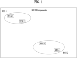
- FIG. 1 is a view illustrating an exemplary configuration of a WLAN system.
- the WLAN system includes at least one Basic Service Set (BSS).
- BSS is a set of Stations (STAs) that are able to communicate with each other by successful synchronization.
- a STA is a logical entity including a physical layer interface between a Media Access Control (MAC) layer and a wireless medium.
- the STA may be any of an Access Point (AP) and a non-AP STA.
- AP Access Point
- non-AP STA a portable terminal manipulated by a user is a non-AP STA. If a terminal is simply called a STA, the STA refers to a non-AP STA.
- the non-AP STA may also be referred to as a terminal, a Wireless Transmit/Receive Unit (WTRU), a User Equipment (UE), a Mobile Station (MS), a mobile terminal, or a mobile subscriber unit.
- WTRU Wireless Transmit/Receive Unit
- UE User Equipment
- MS Mobile Station
- mobile terminal or a mobile subscriber unit.
- An AP is an entity that provides access to a Distribution System (DS) to a STA associated with the AP through a wireless medium.
- the AP may also be referred to as a centralized controller, a Base Station (BS), a Node-B, a Base Transceiver System (BTS), or a site controller.
- BS Base Station
- BTS Base Transceiver System
- BSSs may be classified into infrastructure BSS and Independent BSS (IBSS).
- IBSS Independent BSS
- the BSSs illustrated in FIG. 1 are IBSSs.
- An IBSS refers to a BSS that does not include an AP. Since the IBSS does not include an AP, the IBSS is not allowed to access to the DS and thus forms a self-contained network.
- FIG. 2 is a diagram illustrating another exemplary configuration of a WLAN system.
- Each infrastructure BSS includes one or more STAs and one or more APs.
- communication between non-AP STAs is basically conducted via an AP. However, if a direct link is established between the non-AP STAs, direct communication is also possible between the non-AP STAs.
- a plurality of infrastructure BSSs may be interconnected via a DS.
- the BSSs interconnected via the DS are called an Extended Service Set (ESS).
- STAs included in the ESS may communicate with each other, and a non-AP STA within the same ESS may move from one BSS to another BSS while seamlessly performing communication.
- ESS Extended Service Set
- the DS is a mechanism that connects a plurality of APs to one another.
- the DS is not necessarily a network. As long as it provides a specific distribution service, the DS is not limited to any specific form.
- the DS may be a wireless network such as a mesh network or may be a physical structure that connects APs to one another.
- the Block ACK mechanism is a scheme of transmitting a plurality of ACK/NACK signals in one frame, thereby increasing channel efficiency.
- two response schemes are available: immediate response and delayed response.
- the immediate response scheme may be favorable for transmission of traffic with a short latency in a wide bandwidth, whereas the delayed response scheme may be suitable for a delay-tolerant application.
- a STA transmitting data in the Block ACK mechanism is referred to as an originator, and a STA receiving the data is referred to as a recipient.
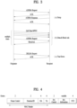
- FIG. 3 is a view illustrating a Block ACK mechanism in a WLAN system.
- the Block ACK mechanism may be initiated by exchange between an Add Block Acknowledgement (ADDBA) request frame and an ADDBA response frame ((a) Setup).
- ADDBA Add Block Acknowledgement
- (a) Setup) an originator may transmit Quality of Service (QoS) data frame blocks to a recipient.
- QoS Quality of Service
- TXOP polled Transmit Opportunity
- EDCA Enhanced Distributed Channel Access
- Reception or non-reception of MAC Protocol Data Units (MPDUs) included in such a frame block may be confirmed from a Block ACK frame received in response to a request made by a BlockAckReq frame ((b)) Data & Block ACK).
- MPDUs MAC Protocol Data Units
- the originator may end the Block ACK mechanism by transmitting a Delete Block Acknowledgement (DELBA) frame to the recipient.
- DELBA Delete Block Acknowledgement
- the recipient may release all resources allocated for Block ACK transmission ((c) Tear Down).
- FIG. 4 is a view illustrating a basic configuration of a Block ACK (BA) frame
- the BA frame may include a MAC Header field, a BA Control field, and a BA Information field.
- the MAC Header field may include a Frame Control field, a Duration/ID field, an RA field, and a TA field.
- the RA field represents an address of a receiving STA and the TA field represents an address of an originating STA.
- FIG. 5 is a view illustrating a detailed configuration of the BA Control field illustrated in FIG. 4 .
- the values of a BA Ack Policy subfield in the BA Control field may have the meanings described in [Table 1] below.
- the BA Ack Policy subfield is set to this value when the sender requires immediate acknowledgment.
- the addressee returns an Ack frame.
- the value 0 is not used for data sent under HT-delayed Block Ack during a PSMP sequence.
- the value 0 is not used in frames transmitted by DMG STAs. 1 No Acknowledgment.
- the addressee sends no immediate response upon receipt of the frame.
- the BA Ack Policy is set to this value when the sender does not require immediate acknowledgment.
- the value 1 is not used in a Basic BlockAck frame outside a PSMP sequence.
- the value 1 is not used in an Multi-TID BlockAck frame.
- Multi-Traffic Identifier (Multi-TID), Compressed Bitmap, and GCR subfields in the BA Control field may determine possible BlockAck frame variants according to the following regulation.
- Multi-TID subfield value Compressed Bitmap subfield value
- GCR subfield value BlockAck frame variant 0 0 0 0 Basic BlockAck 0 1 0 Compressed BlockAck 1 0 0 Extended Compressed BlockAck 1 1 0
- GCR BlockAck 1 0 1 Reserved
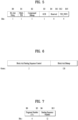
- FIG. 6 is a view illustrating a detailed configuration of the BA Information field illustrated in FIG. 4
- FIG. 7 is a view illustrating a configuration of a Block Ack Starting Sequence Control subfield.
- the BA Information field may include a Block Ack Starting Sequence Control (SSC) subfield and a Block Ack Bitmap subfield.
- SSC Block Ack Starting Sequence Control
- the Block Ack Bitmap subfield is 128 octets in length, and thus may represent the reception statuses of 64 MAC Service Data Units (MSDUs). If bit position n in the Block Ack Bitmap subfield is set to 1, this may indicate that an MPDU having an MPDU sequence control value corresponding to (SSC + n) has been successfully received. Herein, SSC represents the value of the Block Ack Starting Sequence Control subfield. On the other hand, if bit position n of the Block Ack Bitmap field is set to 0, this may indicate that the MPDU having the MPDU sequence control value corresponding to (SSC + n) has not been received.
- Each of the values of an MPDU Sequence Control field and the Block Ack Starting Sequence Control subfield may be treated as a 16-bit unsigned integer. For unused fragment numbers of an MSDU, corresponding bits in the bitmap may be set to 0.
- FIG. 8 is a view illustrating a configuration of a BA Information field in a compressed Block ACK frame
- a Block Ack Bitmap subfield of the BA Information field of the compressed Block ACK frame may be 8 octets in length and indicate the reception statuses of 64 MSDUs and Aggregate MSDUs (A-MSDUs).
- the first bit of the bitmap corresponds to an MSDU or A-MSDU matching a value of a Block Ack Starting Sequence Control subfield, and each bit of the bitmap may sequentially correspond to an MSDU or A-MSDU following the above MSDU or A-MSDU.
- FIG. 9 is a view illustrating a BA Information field in a Multi-TID Block ACK frame
- a TID_INFO subfield of a BA Information field in the Multi-TID Block ACK frame contains information about the number of TIDs in the BA Information field.
- a value of the TID_INFO subfield represents (the number of TIDs corresponding to information of the BA Information field)-1. For example, if the value of the TID_INFO subfield is 2, this may indicate that the BA Information field contains information about three TIDs.
- the Multi-TID Block ACK frame may include a Per TID Info subfield in addition to a Block Ack Starting Sequence Control subfield and a Block Ack Bitmap subfield as illustrated in FIG. 9 .
- the first Per TID Info, Block Ack Starting Sequence Control, and Block Ack Bitmap subfields may be transmitted in correspondence to a lowest TID value, and subsequent repeated subfields may correspond to the next TID. A triplet of these subfields may be repeated per TID.
- FIGS. 10 and 11 are views illustrating cases in which the Block ACK mechanism is applied to DL MU-MIMO.
- an AP may transmit an MU-MIMO data frame to a plurality of STAs (STA1, STA2, and STA3).
- STA1 may receive a BA frame immediately after receiving the DL MU PPDU without a BA request.
- the AP may perform polling for STA2 and STA3 by transmitting BA Request (BAR) frames to STA2 and STA3.
- BAR BA Request
- FIG. 11 illustrates an example in which frames are exchanged without an SIFS after transmission of an MU PPDU. It is assumed in FIG. 11 that Block ACK is set as an ACK policy for all STAs. Therefore, the AP may perform polling by transmitting a BAR frame to every STA.
- FIG. 12 is a view illustrating a UL MU transmission situation to which the present disclosure is applied.
- UL MU transmission may be used in the 802.11ax system.
- the trigger frame may include UL MU allocation information (e.g., resource positions and sizes, STA IDs, a Modulation and Coding Scheme (MCS), an MU type (MIMO, OFDMA, or the like)).
- MCS Modulation and Coding Scheme
- MIMO MU type
- OFDMA OFDMA
- the following information may be transmitted in the trigger frame.
- Power adjustment Tone(/Resource) allocation information (e.g., bitmap), MCS, Nsts, STBC, Coding, Beamformed, etc.
- the AP may acquire a TXOP in which to transmit a trigger frame by contention for medium access. Then, the STAs may transmit UL data frames in a format indicated by the AP, an SIFS after the trigger frame.
- the AP performs an ACK/NACK procedure for the UL MU data frames by a Block ACK (BA) frame.
- BA Block ACK
- flexible application of an ACK policy value per STA may be considered in order to render an ACK/NACK signal transmission scheme of an AP to be flexible.
- a QoS Control field of a UL MU frame has the following configuration. Particularly, the QoS Control field has a 2-bit field indicating an ACK policy in bits 5 and 6.
- SIFS short interframe space
- a non-DMG STA sets the Ack Policy subfield for individually addressed QoS Null (no data) frames to this value.
- the addressed recipient returns a BlockAck frame, either individually or as part of an A-MPDU starting a SIFS after the PPDU carrying the frame, according to theprocedures defined in Block ack procedure, Generation and transmission of BlockAck frames by an HT STA or DMG STA, Operation of HT-delayed block ack, Rules for RD initiator, Rules for RD responder, and Explicit feedback beamforming.
- the Ack Policy subfield is set to this value in all individually addressed frames in which the sender does not require acknowledgment.
- the Ack Policy subfield is alsoset to this value in all group addressed frames that use the QoS frame format exceptwith a TID for which a block ack agreement exists.This value of the Ack Policy subfield is not used for QoS Data frames with a TID forwhich a block ack agreement exists.
- the Ack Policy subfield for group addressed QoS Null (no data) frames is set to this value.
- bit 6 of the Frame Control field (see 9.2.4.1.3 (Type and Subtype subfields)) is set to 1:There might be a response frame to the frame that is received, but it is neither the Ack frame nor any Data frame of subtype +CF-Ack.
- the Ack Policy subfield for QoS CF-Poll and QoS CF-Ack +CF-Poll Data frames is set to this value.
- the above-described Ack Policy field may represent four different values by 2-bit information, and each of the values of the Ack Policy field is defined in [Table 6] to [Table 9].
- ACK policy values used in the following description may have additional meanings as set forth below in addition to the meanings described in [Table 6] to [Table 9]. However, unless otherwise specified, it is assumed that the ACK policy values are pursuant to the definitions in [Table 6] to [Table 9].
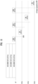
- FIG. 13 is a view illustrating a method for transmitting ACK/NACK signals to a plurality of STAs, using an ACK policy according to an embodiment of the present disclosure.
- the AP may trigger transmission of UL MU frames by transmitting a trigger frame to STA1 to STA4.
- STA1 to STA4 may include Ack Policies in MPDUs.
- FIG. 13 it is assume that STA1 and STA3 set Ack Policy values to 00 and STA2 and STA4 set Ack Policy values to 11.
- the AP transmits a BAs/ACKs (i.e., an M-BA) to STA1 and STA3 at one time, an SIFS after reception of UL MU frames.
- a BAs/ACKs i.e., an M-BA
- the AP may transmit a Block ACK (multi-STA BA) including BA/ACK information for multiple STAs.
- the AP may await receipt of BARs from STA2 and STA4 that have transmitted UL frames with Ack Policy set to 11 indicating BA. Then, STA2 may transmit a BAR in a contention-based manner, and the AP may transmit a BA to STA2 in response to the BAR. Subsequently, STA4 may transmit a BAR in a contention-based manner, and the AP may transmit a BA to STA4 in response to the BAR.
- the UL MU operation may become complex. Particularly when a STA uses Ack Policy set to ⁇ 11', the AP should transmit an ACK after awaiting receipt of a BAR from the STA, the procedure may be delayed.
- a preferred embodiment of the present disclosure proposes that an ACK policy value of '1 1' is not used in a UL MU situation.
- a STA transmits data in UL MU and sets an ACK policy value to a value other than '11' (e.g., '00', '01', or ⁇ 10'). Therefore, when requesting an ACK/NACK, the STA preferably operates by setting Ack Policy to '00'.
- the above UL MU situation may be different from the afore-described DL MU situation.
- the AP may uniformly determine ACK policy values for a plurality of STAs, the AP may select a BAR-based ACK policy for some STA according to the situation of the AP.
- FIG. 14 is a view illustrating a case in which a BAR-based ACK policy value is not used according to an embodiment of the present disclosure.
- an AP may trigger transmission of UL MU frames from a plurality of STAs by transmitting a trigger frame.
- each of STA1 to STA4 transmits a UL MU frame, requesting reception of an ACK/NACK for the UL MU frame in the example of FIG. 14 .
- STA1 to STA4 transmit UL MU frames with Ack Policy set to '00', and thus receive ACK/NACK signals after an SIFS from the AP.
- the AP is shown in FIG. 14 as transmitting ACK/NACK signals in an M-BA, by way of example.
- the AP may transmit all of ACK/NACK signals for STA1 to STA4 in the M-BA.
- FIGS. 15 and 16 are views additionally illustrating a UL multiple access situation to which the present disclosure is applied.
- FIG. 15 is a view illustrating a situation in which STA1 to STA4 transmit UL MU PPDUs in response to a trigger frame transmitted by an AP, as described above.
- STA1, STA2, and STA3 request ACK/NACK signals for their transmitted UL MU PPDUs
- STA1, STA2, and STA3 preferably transmit the UL MU PPDUs with Ack Policy set to '00'.
- STA4 does not request an ACK/NACK signal for its transmitted UL MU PPDU, and thus may transmit the UL MU PPDU with Ack Policy set to '01'.
- the AP may transmit ACK/NACK signals in a DL OFDMA BA or M-BA to STA1, STA2, and STA3 that have set Ack Policy to '00'.
- the AP may transmit a DL MU PPDU together with a trigger frame.
- the AP may transmit a DL ACK for a UL MU PPDU for which an ACK is needed.
- trigger information for transmission of an ACK for a DL MU PPDU may be included or may be implicitly derived.
- a DL ACK frame may be transmitted in an OFDMA or M-BA form. That is, each piece of ACK information transmitted to each STA may be configured in an OFDMA frame or ACK information transmitted to all STAs may be aggregated in one frame.
- a hybrid scheme of the two schemes is also possible, in which an M-BA is used only within 20MHz, and OFDMA is used in a bandwidth equal to or larger than 20MHz.
- an AP sets a per-STA ACK policy by a trigger frame.
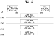
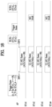
- FIGS. 17 and 18 are views illustrating ACK policy values in a trigger frame transmitted by an AP.
- the AP may set the same or different ACK policies for all STAs in a trigger frame.
- FIG. 18 illustrates an example of setting an ACK Policy on a STA basis.
- Ack Policy (A_P) is set to 00 (implicit BA/ACK for single MPDU) for STA1 and STA3, and A_P is set to 11 (Block ACK) for STA2 and STA4. Therefore, the AP may receive UL MU frames, transmit BAs/ACKs for STA1 and STA3 in an M-BA, and then allocate resources for MU BAR transmission to STA2 and STA4 by a trigger frame
- FIG. 19 is a block diagram of apparatuses for implementing the above-described methods.
- a wireless apparatus 800 of FIG. 19 may correspond to the above-described specific STA, and a wireless apparatus 850 of FIG. 19 may correspond to the above-described AP.
- the STA 800 may include a processor 810, a memory 820, and a transceiver 830, and the AP 850 may include a processor 860, a memory 870, and a transceiver 880.
- the transceivers 830 and 880 may transmit/receive a wireless signal and may be implemented in a physical layer of IEEE 802.11/3GPP.
- the processors 810 and 860 are implemented in a physical layer and/or a MAC layer and are connected to the transceivers 830 and 880.
- the processors 810 and 860 may perform the above-described UL MU scheduling procedure.
- the processors 810 and 860 and/or the transceivers 830 and 880 may include an Application-Specific Integrated Circuit (ASIC), other chipsets, a logical circuit, and/or a data processor.
- the memories 820 and 870 may include a Read-Only Memory (ROM), a Random Access Memory (RAM), a flash memory, a memory card, a storage medium, and/or a storage unit. If an embodiment is performed by software, the above-described methods may be executed in the form of a module (e.g., a process or a function) performing the above-described functions.
- the module may be stored in the memories 820 and 870 and executed by the processors 810 and 860.
- the memories 820 and 870 may be located at the interior or exterior of the processors 810 and 860 and may be connected to the processors 810 and 860 via known means.
- present disclosure has been described in the context of an IEEE 802.11 WLAN system, the present disclosure is not limited thereto.
- the present disclosure is applicable in the same manner to various wireless systems in which an AP is capable of performing a Block ACK mechanism for a plurality of STAs.
Landscapes
- Engineering & Computer Science (AREA)
- Signal Processing (AREA)
- Computer Networks & Wireless Communication (AREA)
- Mobile Radio Communication Systems (AREA)
- Communication Control (AREA)
Abstract
Description
- The present disclosure relates to a method and apparatus for transmitting and receiving an Acknowledgment/Negative Acknowledgment (ACK/NACK) signal for multi-user or multi-Station (STA) data, based on an ACK policy value in a Wireless Local Area Network (WLAN) system.
- WLAN technology has been standardized as Institute of Electrical and Electronics Engineers (IEEE) 802.11. IEEE 802.11a and IEEE 802.11b use an unlicensed band at 2.4GHz or 5GHz. IEEE 802.11b provides a transmission rate of 1 1Mbps, and IEEE 802.1 1a provides a transmission rate of 54Mbps. IEEE 802.11g provides a transmission rate of 54Mbps by applying Orthogonal Frequency Division Multiplexing (OFDM) at 2.4GHz. IEEE 802.11n provides a transmission rate of 300Mbps for four spatial streams by applying Multiple Input Multiple Output (MIMO)-OFDM. IEEE 802.11n supports a channel bandwidth of up to 40MHz and, in this case, provides a transmission rate of 600Mbps.
- The above-described WLAN standards have evolved into IEEE 802.11ac that uses a bandwidth of up to 160MHz and supports a transmission rate of up to 1Gbit/s for eight spatial streams, and IEEE 802.11ax standardization is under discussion.
- In the IEEE 802.11ax standard, Uplink (UL) Orthogonal Frequency Division Multiple Access (OFDMA) transmission and UL Multi-User (MU) transmission will be used. Thus, an Access Point (AP) may receive UL MU frames from a plurality of Stations (STAs) in the same transmission opportunity and needs to transmit an Acknowledgement (ACK) frame in response to the UL MU frames.
- In this case, efficient transmission of Acknowledgement/Negative Acknowledgement (ACK/NACK) signals to a plurality of STAs in a Block ACK (BA) frame may be considered. However, overhead may be problematic due to an increased size of an MU BA or M-BA frame for the plurality of STAs.
- Moreover, if some of the plurality of STAs request a BA and others request a normal ACK, the procedure becomes complex and an ACK/NACK operation may be delayed.
- Hereinafter, a method and apparatus for efficiently transmitting an ACK/NACK signal in the above-described UL MU transmission situation will be described.
- In an aspect of the present disclosure, a method for accessing an access point (AP) in a multi-user scheme by a station (STA) in a wireless local area network (WLAN) system includes receiving a trigger frame from the AP, and transmitting data to the AP in a multi-user access scheme in response to the trigger frame. The STA sets an ACK policy value for the data transmitted based on the trigger frame to a value other than a first ACK policy value requesting transmission of an ACK signal based on a block ACK request.
- The STA may set the ACK policy value for the data transmitted based on the trigger frame to a second ACK policy value requesting a normal ACK or an immediate transmission block ACK request.
- The method may further include, after transmission of the data with the ACK policy value set to the second ACK policy value, receiving an ACK/NACK signal for the data from the AP.
- The ACK/NACK signal may be received a short inter-frame space (SIFS) after the transmission of the data with the ACK policy value set to the second ACK policy value.
- If downlink data is received in a multi-user scheme from the AP, an ACK policy value for the downlink data may be set to one of a plurality of ACK policy values including the first ACK policy value.
- The plurality of ACK policy values may include '01' requesting a normal ACK or an immediate transmission block ACK request, '01' requesting no ACK, `10' requesting no explicit ACK or a power save multi-poll (PSMP) ACK, and '11' requesting an ACK based on a block ACK request.
- The first ACK policy value may be `11', and the second ACK policy value may be '00'.
- In another aspect of the present disclosure, a STA for accessing an AP in a multi-user scheme in a WLAN system includes a transceiver configured to receive a trigger frame from the AP, and transmit data to the AP in a multi-user access scheme in response to the trigger frame, and a processor connected to the transceiver and configured to provide the data to the transceiver. The processor is configured to set an ACK policy value for the data transmitted based on the trigger frame to a value other than a first ACK policy value requesting transmission of an ACK signal based on a block ACK request.
- The processor may be configured to set the ACK policy value for the data transmitted based on the trigger frame to a second ACK policy value requesting a normal ACK or an immediate transmission block ACK request.
- If the transceiver receives downlink data in a multi-user scheme from the AP, the processor may be configured to check an ACK policy value for the downlink data set to one of a plurality of ACK policy values including the first ACK policy value.
- In another aspect of the present disclosure, a method for receiving data from a plurality of STAs in a multi-user scheme by an AP in a WLAN system includes transmitting a trigger frame to the plurality of STAs, and receiving data from the plurality of STAs in a multi-user access scheme. An ACK policy value for the data received after the transmission of the trigger frame is set to a value other than a first ACK policy value requesting transmission of an ACK signal based on a block ACK request.
- The ACK policy value for the data received after the transmission of the trigger frame may be set to a second ACK policy value requesting a normal ACK or an immediate transmission block ACK request.
- If the AP transmits downlink data to the plurality of STAs in a multi-user scheme, the AP may set an ACK policy value for the downlink data to one of a plurality of ACK policy values including the first ACK policy value.
- In another aspect of the present disclosure, an AP for receiving data from a plurality of STAs in a multi-user scheme in a WLAN system includes a transceiver configured to transmit a trigger frame to the plurality of STAs, and receive data from the plurality of STAs in a multi-user access scheme, and a processor connected to the transceiver and configured to process the data. The processor is configured to operate in response to an ACK policy value for the data set to a value other than a first ACK policy value requesting transmission of an ACK signal based on a block ACK request.
- The ACK policy value for the data received after the transmission of the trigger frame may be set to a second ACK policy value requesting a normal ACK or an immediate transmission block ACK request.
- According to the present disclosure as described above, an Access Point (AP) may efficiently transmit Acknowledgment/Negative Acknowledgment (ACK/NACK) signals to a plurality of Stations (STAs) in an Uplink (UL) Multi-User (MU) transmission situation.
-
-
FIG. 1 is a view illustrating an exemplary configuration of a Wireless Local Area Network (WLAN) system. -
FIG. 2 is a view illustrating another exemplary configuration of a WLAN system. -
FIG. 3 is a view illustrating a Block Acknowledgment (ACK) mechanism used in a WLAN system. -
FIG. 4 is a view illustrating a basic configuration of a Block ACK frame -
FIG. 5 is a view illustrating a detailed configuration of a BA Control field illustrated inFIG. 4 . -
FIG. 6 is a view illustrating a detailed configuration of a Block ACK (BA) Information field illustrated inFIG. 4 . -
FIG. 7 is a view illustrating a configuration of a Block Ack Starting Sequence Control subfield. -
FIG. 8 is a view illustrating a configuration of a BA Information field of a compressed Block ACK frame. -
FIG. 9 is a view illustrating a BA Information field of a Multi-Traffic Identifier (TID) Block ACK frame -
FIGS. 10 and11 are views illustrating cases in which a Block ACK mechanism is applied to Downlink (DL) Multi-User Multiple Input Multiple Output (MU-MIMO). -
FIG. 12 is a view illustrating an Uplink (UL) MU transmission situation to which the present disclosure is applied. -
FIG. 13 is a view illustrating a method for transmitting ACK/NACK signals to a plurality of STAs, using an ACK policy according to an embodiment of the present disclosure. -
FIG. 14 is a view illustrating a case in which a Block ACK Request (BAR)-based ACK policy value is not used according to an embodiment of the present disclosure. -
FIGS. 15 and 16 are views additionally illustrating a UL multiple access situation to which the present disclosure is applied. -
FIGS. 17 and18 are views illustrating ACK policy values in a trigger frame transmitted by an Access Point (AP). -
FIG. 19 is a block diagram of apparatuses for implementing the above methods. - Reference will now be made in detail to the exemplary embodiments of the present disclosure, examples of which are illustrated in the accompanying drawings. The detailed description, which will be given below with reference to the accompanying drawings, is intended to explain exemplary embodiments of the present disclosure, rather than to show the only embodiments that can be implemented according to the present disclosure.
- The following detailed description includes specific details in order to provide a thorough understanding of the present disclosure. However, it will be apparent to those skilled in the art that the present disclosure may be practiced without such specific details. In some instances, known structures and devices are omitted or are shown in block diagram form, focusing on important features of the structures and devices, so as not to obscure the concept of the present disclosure.
- As described above, the following description relates to a method for efficiently utilizing a channel having a wide band in a Wireless Local Area Network (WLAN) system and an apparatus therefor. To this end, a WLAN system to which the present disclosure is applicable will first be described in detail.
-
FIG. 1 is a view illustrating an exemplary configuration of a WLAN system. - As illustrated in
FIG. 1 , the WLAN system includes at least one Basic Service Set (BSS). A BSS is a set of Stations (STAs) that are able to communicate with each other by successful synchronization. - A STA is a logical entity including a physical layer interface between a Media Access Control (MAC) layer and a wireless medium. The STA may be any of an Access Point (AP) and a non-AP STA. Among STAs, a portable terminal manipulated by a user is a non-AP STA. If a terminal is simply called a STA, the STA refers to a non-AP STA. The non-AP STA may also be referred to as a terminal, a Wireless Transmit/Receive Unit (WTRU), a User Equipment (UE), a Mobile Station (MS), a mobile terminal, or a mobile subscriber unit.
- An AP is an entity that provides access to a Distribution System (DS) to a STA associated with the AP through a wireless medium. The AP may also be referred to as a centralized controller, a Base Station (BS), a Node-B, a Base Transceiver System (BTS), or a site controller.
- BSSs may be classified into infrastructure BSS and Independent BSS (IBSS).
- The BSSs illustrated in
FIG. 1 are IBSSs. An IBSS refers to a BSS that does not include an AP. Since the IBSS does not include an AP, the IBSS is not allowed to access to the DS and thus forms a self-contained network. -
FIG. 2 is a diagram illustrating another exemplary configuration of a WLAN system. - BSSs illustrated in
FIG. 2 are infrastructure BSSs. Each infrastructure BSS includes one or more STAs and one or more APs. In the infrastructure BSS, communication between non-AP STAs is basically conducted via an AP. However, if a direct link is established between the non-AP STAs, direct communication is also possible between the non-AP STAs. - As illustrated in
FIG. 2 , a plurality of infrastructure BSSs may be interconnected via a DS. The BSSs interconnected via the DS are called an Extended Service Set (ESS). STAs included in the ESS may communicate with each other, and a non-AP STA within the same ESS may move from one BSS to another BSS while seamlessly performing communication. - The DS is a mechanism that connects a plurality of APs to one another. The DS is not necessarily a network. As long as it provides a specific distribution service, the DS is not limited to any specific form. For example, the DS may be a wireless network such as a mesh network or may be a physical structure that connects APs to one another.
- Now, a description will be given of a Block ACK mechanism in a WLAN system based on the above description.
- The Block ACK mechanism is a scheme of transmitting a plurality of ACK/NACK signals in one frame, thereby increasing channel efficiency. For the Block ACK mechanism, two response schemes are available: immediate response and delayed response. The immediate response scheme may be favorable for transmission of traffic with a short latency in a wide bandwidth, whereas the delayed response scheme may be suitable for a delay-tolerant application. Unless otherwise specified in the following description, a STA transmitting data in the Block ACK mechanism is referred to as an originator, and a STA receiving the data is referred to as a recipient.
-
FIG. 3 is a view illustrating a Block ACK mechanism in a WLAN system. - As illustrated in
FIG. 3 , the Block ACK mechanism may be initiated by exchange between an Add Block Acknowledgement (ADDBA) request frame and an ADDBA response frame ((a) Setup). After the Block ACK mechanism is initiated in this manner, an originator may transmit Quality of Service (QoS) data frame blocks to a recipient. As the originator wins a polled Transmit Opportunity (TXOP) or an Enhanced Distributed Channel Access (EDCA) contention, transmission of these blocks may be started. The number of frames in a block may be limited. Reception or non-reception of MAC Protocol Data Units (MPDUs) included in such a frame block may be confirmed from a Block ACK frame received in response to a request made by a BlockAckReq frame ((b)) Data & Block ACK). - If the originator does not have any more transmission data and a final Block ACK exchange is completed, the originator may end the Block ACK mechanism by transmitting a Delete Block Acknowledgement (DELBA) frame to the recipient. Upon receipt of the DELBA frame, the recipient may release all resources allocated for Block ACK transmission ((c) Tear Down).
-
FIG. 4 is a view illustrating a basic configuration of a Block ACK (BA) frame - As illustrated in
FIG. 4 , the BA frame may include a MAC Header field, a BA Control field, and a BA Information field. The MAC Header field may include a Frame Control field, a Duration/ID field, an RA field, and a TA field. Herein, the RA field represents an address of a receiving STA and the TA field represents an address of an originating STA. -
FIG. 5 is a view illustrating a detailed configuration of the BA Control field illustrated inFIG. 4 . - The values of a BA Ack Policy subfield in the BA Control field may have the meanings described in [Table 1] below.
[Table 1] Value Meaning 0 Normal Acknowledgment. The BA Ack Policy subfield is set to this value when the sender requires immediate acknowledgment. The addressee returns an Ack frame. The value 0 is not used for data sent under HT-delayed Block Ack during a PSMP sequence.The value 0 is not used in frames transmitted by DMG STAs.1 No Acknowledgment. The addressee sends no immediate response upon receipt of the frame. The BA Ack Policy is set to this value when the sender does not require immediate acknowledgment. The value 1 is not used in a Basic BlockAck frame outside a PSMP sequence.The value 1 is not used in an Multi-TID BlockAck frame. - Meanwhile, Multi-Traffic Identifier (Multi-TID), Compressed Bitmap, and GCR subfields in the BA Control field may determine possible BlockAck frame variants according to the following regulation.
[Table 2] Multi-TID subfield value Compressed Bitmap subfield value GCR subfield value BlockAck frame variant 0 0 0 Basic BlockAck 0 1 0 Compressed BlockAck 1 0 0 Extended Compressed BlockAck 1 1 0 Multi-TID BlockAck 0 0 1 Reserved 0 1 1 GCR BlockAck 1 0 1 Reserved 1 1 1 Reserved -
FIG. 6 is a view illustrating a detailed configuration of the BA Information field illustrated inFIG. 4 , andFIG. 7 is a view illustrating a configuration of a Block Ack Starting Sequence Control subfield. - As illustrated in
FIG. 6 , the BA Information field may include a Block Ack Starting Sequence Control (SSC) subfield and a Block Ack Bitmap subfield. - As illustrated in
FIG. 6 , the Block Ack Bitmap subfield is 128 octets in length, and thus may represent the reception statuses of 64 MAC Service Data Units (MSDUs). If bit position n in the Block Ack Bitmap subfield is set to 1, this may indicate that an MPDU having an MPDU sequence control value corresponding to (SSC + n) has been successfully received. Herein, SSC represents the value of the Block Ack Starting Sequence Control subfield. On the other hand, if bit position n of the Block Ack Bitmap field is set to 0, this may indicate that the MPDU having the MPDU sequence control value corresponding to (SSC + n) has not been received. Each of the values of an MPDU Sequence Control field and the Block Ack Starting Sequence Control subfield may be treated as a 16-bit unsigned integer. For unused fragment numbers of an MSDU, corresponding bits in the bitmap may be set to 0. -
FIG. 8 is a view illustrating a configuration of a BA Information field in a compressed Block ACK frame - As illustrated in
FIG. 8 , a Block Ack Bitmap subfield of the BA Information field of the compressed Block ACK frame may be 8 octets in length and indicate the reception statuses of 64 MSDUs and Aggregate MSDUs (A-MSDUs). The first bit of the bitmap corresponds to an MSDU or A-MSDU matching a value of a Block Ack Starting Sequence Control subfield, and each bit of the bitmap may sequentially correspond to an MSDU or A-MSDU following the above MSDU or A-MSDU. -
FIG. 9 is a view illustrating a BA Information field in a Multi-TID Block ACK frame - A TID_INFO subfield of a BA Information field in the Multi-TID Block ACK frame contains information about the number of TIDs in the BA Information field. Specifically, a value of the TID_INFO subfield represents (the number of TIDs corresponding to information of the BA Information field)-1. For example, if the value of the TID_INFO subfield is 2, this may indicate that the BA Information field contains information about three TIDs.
- Meanwhile, the Multi-TID Block ACK frame may include a Per TID Info subfield in addition to a Block Ack Starting Sequence Control subfield and a Block Ack Bitmap subfield as illustrated in
FIG. 9 . The first Per TID Info, Block Ack Starting Sequence Control, and Block Ack Bitmap subfields may be transmitted in correspondence to a lowest TID value, and subsequent repeated subfields may correspond to the next TID. A triplet of these subfields may be repeated per TID. -
FIGS. 10 and11 are views illustrating cases in which the Block ACK mechanism is applied to DL MU-MIMO. - As illustrated in
FIGS. 10 and11 , an AP may transmit an MU-MIMO data frame to a plurality of STAs (STA1, STA2, and STA3). - In
FIG. 10 , it is assumed that frames are exchanged a Short Inter-Frame Space (SIFS) after transmission of a Multi-User PLCP Protocol Data Unit (MU PPDU). It is assumed inFIG. 10 that Implicit Block ACK Request is set as an ACK policy for STA1, and Block ACK is set as an ACK policy for STA2 and STA3. Therefore, STA1 may receive a BA frame immediately after receiving the DL MU PPDU without a BA request. On the other hand, the AP may perform polling for STA2 and STA3 by transmitting BA Request (BAR) frames to STA2 and STA3. STA2 and STA3 may transmit BA frames in response to the BAR frames. - Meanwhile,
FIG. 11 illustrates an example in which frames are exchanged without an SIFS after transmission of an MU PPDU. It is assumed inFIG. 11 that Block ACK is set as an ACK policy for all STAs. Therefore, the AP may perform polling by transmitting a BAR frame to every STA. -
FIG. 12 is a view illustrating a UL MU transmission situation to which the present disclosure is applied. - As described above, UL MU transmission may be used in the 802.11ax system. As illustrated in
FIG. 12 , as an AP transmits a trigger frame to a plurality of STAs (e.g., STA1 to STA4), UL MU transmission may be started. The trigger frame may include UL MU allocation information (e.g., resource positions and sizes, STA IDs, a Modulation and Coding Scheme (MCS), an MU type (MIMO, OFDMA, or the like)). Specifically, for example, the following information may be transmitted in the trigger frame.[Table 3] Duration, Number of allocations (N), each allocation's information, and SU/MU AID (as many as the number of STAs in the case of MU). Power adjustment, Tone(/Resource) allocation information (e.g., bitmap), MCS, Nsts, STBC, Coding, Beamformed, etc. - Meanwhile, as illustrated in
FIG. 12 , the AP may acquire a TXOP in which to transmit a trigger frame by contention for medium access. Then, the STAs may transmit UL data frames in a format indicated by the AP, an SIFS after the trigger frame. In the present disclosure, it is assumed that the AP performs an ACK/NACK procedure for the UL MU data frames by a Block ACK (BA) frame. - In UL multiple access, flexible application of an ACK policy value per STA may be considered in order to render an ACK/NACK signal transmission scheme of an AP to be flexible.
- A QoS Control field of a UL MU frame has the following configuration. Particularly, the QoS Control field has a 2-bit field indicating an ACK policy in
bits 5 and 6.


- The values of the Ack Policy field illustrated in [Table 4] and [Table 5] are set as follows.
[Table 6] Ack Policy ==00 Normal Ack or Implicit Block Ack Request.In a frame that is a non-A-MPDU frame or VHT single MPDU:The addressed recipient returns an Ack or QoS +CF-Ack frame after a short interframe space (SIFS) period, according to the procedures defined in Ack procedure and HCCA transfer rules. A non-DMG STA sets the Ack Policy subfield for individually addressed QoS Null (no data) frames to this value. Otherwise: The addressed recipient returns a BlockAck frame, either individually or as part of an A-MPDU starting a SIFS after the PPDU carrying the frame, according to theprocedures defined in Block ack procedure, Generation and transmission of BlockAck frames by an HT STA or DMG STA, Operation of HT-delayed block ack, Rules for RD initiator, Rules for RD responder, and Explicit feedback beamforming. [Table 7] Ack Policy ==01No AckThe addressed recipient takes no action upon receipt of the frame. The Ack Policy subfield is set to this value in all individually addressed frames in which the sender does not require acknowledgment. The Ack Policy subfield is alsoset to this value in all group addressed frames that use the QoS frame format exceptwith a TID for which a block ack agreement exists.This value of the Ack Policy subfield is not used for QoS Data frames with a TID forwhich a block ack agreement exists. The Ack Policy subfield for group addressed QoS Null (no data) frames is set to this value. [Table 8] Ack Policy ==10No explicit acknowledgment or PSMP Ack or MU Ack.When bit 6 of the Frame Control field (see 9.2.4.1.3 (Type and Subtype subfields)) is set to 1:There might be a response frame to the frame that is received, but it is neither the Ack frame nor any Data frame of subtype +CF-Ack.The Ack Policy subfield for QoS CF-Poll and QoS CF-Ack +CF-Poll Data frames is set to this value. Whenbit 6 of the Frame Control field (see 9.2.4.1.3 (Type and Subtype subfields)) is set to 0:The acknowledgment for a frame indicating PSMP Ack when it appears in a PSMP downlink transmission time (PSMP-DTT) is to be received in a later PSMP uplink transmission time (PSMP-UTT).The acknowledgment for a frame indicating PSMP Ack when it appears in a PSMPUTT is to be received in a later PSMP-DTT.For a frame that is carried in a DL HE MU PPDU:The Ack Policy subfield for the frame that solicits an immediate response in a HE Trigger-based PPDU is set to this value (MU Ack).The addressed recipient returns an Ack, BlockAck, or Multi-STA BlockAck frame in the HE trigger-based PPDU format after a SIFS period, according to the procedures defined in 10.3.2.11.2 (Acknowledgement procedure for HE MU PPDU in MU format) and 25.5.2 (UL MU operation). (#2445)NOTE?Bit 6 of the Frame Control field (see 9.2.4.1.3 (Type and Subtype subfields)) indicates the absence of a data Frame Body field. When equal to 1, the QoS Data frame contains no Frame Body field, and any response is generated in response to a QoS CF-Poll or QoS CF-Ack +CF-Poll frame, but does not signify an acknowledgment of data. When set to 0, the QoS Data frame contains a Frame Body field, which is acknowledged as described in 10.29.2.7 (PSMP acknowledgment rules)..[Table 9] Ack Policy ==11Block AckThe addressed recipient takes no action upon the receipt of the frame except for recording the state. The recipient can expect a BlockAckReq frame in the future to which it responds using the procedure described in Block acknowledgment (block ack). - That is, the above-described Ack Policy field may represent four different values by 2-bit information, and each of the values of the Ack Policy field is defined in [Table 6] to [Table 9]. In the following description, a method for transmitting ACK/NACK signals to a plurality of STAs more flexibly by an AP through application of the Ack Policy field to a UL MU situation. ACK policy values used in the following description may have additional meanings as set forth below in addition to the meanings described in [Table 6] to [Table 9]. However, unless otherwise specified, it is assumed that the ACK policy values are pursuant to the definitions in [Table 6] to [Table 9].
-
FIG. 13 is a view illustrating a method for transmitting ACK/NACK signals to a plurality of STAs, using an ACK policy according to an embodiment of the present disclosure. - As in the example of
FIG. 13 , the AP may trigger transmission of UL MU frames by transmitting a trigger frame to STA1 to STA4. Accordingly, when transmitting the UL MU frames, STA1 to STA4 may include Ack Policies in MPDUs. InFIG. 13 , it is assume that STA1 and STA3 set Ack Policy values to 00 and STA2 and STA4 set Ack Policy values to 11. - It is assumed in this embodiment that if the Ack Policy value of a UL MU frame is 00, this indicates an implicit BA/ACK request for a single MPDU, and the AP may simultaneously transmit a BA (i.e., an M-BA) to STAs that have transmitted UL MU frames with Ack Policy==00 (implicit BA/ACK), immediately an SIFS after receiving the UL MU frames from the STAs. The M-BA is assumed to include ACKsBAs for the plurality of STAs. That is, upon receipt of one or more UL MU frames with Ack Policy==00, the AP transmits an M-BA an SIFS later. Then, after receiving BARs from STAs that have transmitted UL MU frames with Ack Policy set to 11 indicating BA, the AP may transmit a Block ACK to the STAs that have transmitted the BARs.
- In
FIG. 13 , since Ack Policies of STA1 and STA3 are 00 (implicit BA or ACK for single MPDU), the AP transmits a BAs/ACKs (i.e., an M-BA) to STA1 and STA3 at one time, an SIFS after reception of UL MU frames. Herein, the AP may transmit a Block ACK (multi-STA BA) including BA/ACK information for multiple STAs. - Subsequently, the AP may await receipt of BARs from STA2 and STA4 that have transmitted UL frames with Ack Policy set to 11 indicating BA. Then, STA2 may transmit a BAR in a contention-based manner, and the AP may transmit a BA to STA2 in response to the BAR. Subsequently, STA4 may transmit a BAR in a contention-based manner, and the AP may transmit a BA to STA4 in response to the BAR.
- However, if ACK policy values are flexibly used for each of a plurality of STAs as in
FIG. 13 , the UL MU operation may become complex. Particularly when a STA uses Ack Policy set to `11', the AP should transmit an ACK after awaiting receipt of a BAR from the STA, the procedure may be delayed. - Accordingly, a preferred embodiment of the present disclosure proposes that an ACK policy value of '1 1' is not used in a UL MU situation. Thus, it is assumed that a STA transmits data in UL MU and sets an ACK policy value to a value other than '11' (e.g., '00', '01', or `10'). Therefore, when requesting an ACK/NACK, the STA preferably operates by setting Ack Policy to '00'.
- The above UL MU situation may be different from the afore-described DL MU situation. In DL MU, since an AP may uniformly determine ACK policy values for a plurality of STAs, the AP may select a BAR-based ACK policy for some STA according to the situation of the AP.
-
FIG. 14 is a view illustrating a case in which a BAR-based ACK policy value is not used according to an embodiment of the present disclosure. - As described in
FIG. 14 , an AP may trigger transmission of UL MU frames from a plurality of STAs by transmitting a trigger frame. Thus, it is assumed that each of STA1 to STA4 transmits a UL MU frame, requesting reception of an ACK/NACK for the UL MU frame in the example ofFIG. 14 . Accordingly, STA1 to STA4 transmit UL MU frames with Ack Policy set to '00', and thus receive ACK/NACK signals after an SIFS from the AP. - Meanwhile, the AP is shown in
FIG. 14 as transmitting ACK/NACK signals in an M-BA, by way of example. Thus, the AP may transmit all of ACK/NACK signals for STA1 to STA4 in the M-BA. -
FIGS. 15 and 16 are views additionally illustrating a UL multiple access situation to which the present disclosure is applied. -
FIG. 15 is a view illustrating a situation in which STA1 to STA4 transmit UL MU PPDUs in response to a trigger frame transmitted by an AP, as described above. InFIG. 15 , since STA1, STA2, and STA3 request ACK/NACK signals for their transmitted UL MU PPDUs, STA1, STA2, and STA3 preferably transmit the UL MU PPDUs with Ack Policy set to '00'. In contrast, STA4 does not request an ACK/NACK signal for its transmitted UL MU PPDU, and thus may transmit the UL MU PPDU with Ack Policy set to '01'. - Therefore, the AP may transmit ACK/NACK signals in a DL OFDMA BA or M-BA to STA1, STA2, and STA3 that have set Ack Policy to '00'.
- Meanwhile, as illustrated in
FIG. 16 , the AP may transmit a DL MU PPDU together with a trigger frame. Thus, after the STAs transmit UL MU PPDUs or UL ACKs, the AP may transmit a DL ACK for a UL MU PPDU for which an ACK is needed. Herein, trigger information for transmission of an ACK for a DL MU PPDU may be included or may be implicitly derived. - A DL ACK frame may be transmitted in an OFDMA or M-BA form. That is, each piece of ACK information transmitted to each STA may be configured in an OFDMA frame or ACK information transmitted to all STAs may be aggregated in one frame. A hybrid scheme of the two schemes is also possible, in which an M-BA is used only within 20MHz, and OFDMA is used in a bandwidth equal to or larger than 20MHz.
- If compared to a DL MU situation, different ACK policy values are set for different STAs in a UL MU situation as described above, the procedure may become complex and an unnecessary delay may occur. Therefore, it is preferred not to use an ACK policy value of '11'.
- However, to solve the problem of selecting a different ACK policy value for each STA in a UL MU situation as described above and flexibly use an ACK policy according to the state of each STA, another embodiment of the present disclosure proposes that an AP sets a per-STA ACK policy by a trigger frame.
-
FIGS. 17 and18 are views illustrating ACK policy values in a trigger frame transmitted by an AP. - The AP may set the same or different ACK policies for all STAs in a trigger frame.
FIG. 17 illustrates an example of setting the same Ack Policy==00 (implicit BA) for all STAs, andFIG. 18 illustrates an example of setting an ACK Policy on a STA basis. - In the example of
FIG. 18 , Ack Policy (A_P) is set to 00 (implicit BA/ACK for single MPDU) for STA1 and STA3, and A_P is set to 11 (Block ACK) for STA2 and STA4. Therefore, the AP may receive UL MU frames, transmit BAs/ACKs for STA1 and STA3 in an M-BA, and then allocate resources for MU BAR transmission to STA2 and STA4 by a trigger frame -
FIG. 19 is a block diagram of apparatuses for implementing the above-described methods. - A wireless apparatus 800 of
FIG. 19 may correspond to the above-described specific STA, and a wireless apparatus 850 ofFIG. 19 may correspond to the above-described AP. - The STA 800 may include a processor 810, a memory 820, and a transceiver 830, and the AP 850 may include a processor 860, a memory 870, and a transceiver 880. The transceivers 830 and 880 may transmit/receive a wireless signal and may be implemented in a physical layer of IEEE 802.11/3GPP. The processors 810 and 860 are implemented in a physical layer and/or a MAC layer and are connected to the transceivers 830 and 880. The processors 810 and 860 may perform the above-described UL MU scheduling procedure.
- The processors 810 and 860 and/or the transceivers 830 and 880 may include an Application-Specific Integrated Circuit (ASIC), other chipsets, a logical circuit, and/or a data processor. The memories 820 and 870 may include a Read-Only Memory (ROM), a Random Access Memory (RAM), a flash memory, a memory card, a storage medium, and/or a storage unit. If an embodiment is performed by software, the above-described methods may be executed in the form of a module (e.g., a process or a function) performing the above-described functions. The module may be stored in the memories 820 and 870 and executed by the processors 810 and 860. The memories 820 and 870 may be located at the interior or exterior of the processors 810 and 860 and may be connected to the processors 810 and 860 via known means.
- The detailed description of the preferred embodiments of the present disclosure has been given to enable those skilled in the art to implement and practice the present disclosure. Although the present disclosure has been described with reference to the preferred embodiments, those skilled in the art will appreciate that various modifications and variations can be made in the present disclosure without departing from the spirit or scope of the present disclosure described in the appended claims. Accordingly, the present disclosure should not be limited to the specific embodiments described herein, but should be accorded the broadest scope consistent with the principles and novel features disclosed herein.
- While the present disclosure has been described in the context of an IEEE 802.11 WLAN system, the present disclosure is not limited thereto. The present disclosure is applicable in the same manner to various wireless systems in which an AP is capable of performing a Block ACK mechanism for a plurality of STAs.
- Advantageous examples of the present disclosure can be phrased as follows:
- [Aspect 1] A method for accessing an access point (AP) by a multi-user scheme by a station (STA) in a wireless local area network (WLAN) system, the method comprising:
- receiving a trigger frame from the AP; and
- transmitting data to the AP in a multi-user access scheme in response to the trigger frame,
- wherein the STA sets an ACK policy value for the data transmitted based on the trigger frame to a value other than a first ACK policy value requesting transmission of an ACK signal based on a block ACK request.
- [Aspect 2] The method according to
aspect 1, wherein the STA sets the ACK policy value for the data transmitted based on the trigger frame to a second ACK policy value requesting a normal ACK or an immediate transmission block ACK request. - [Aspect 3] The method according to
aspect 2, further comprising, after transmission of the data with the ACK policy value set to the second ACK policy value, receiving an ACK/NACK signal for the data from the AP. - [Aspect 4] The method according to
aspect 3, wherein the ACK/NACK signal is received a short inter-frame space (SIFS) after the transmission of the data with the ACK policy value set to the second ACK policy value. - [Aspect 5] The method according to
aspect 1, wherein if downlink data is received in a multi-user scheme from the AP, an ACK policy value for the downlink data is set to one of a plurality of ACK policy values including the first ACK policy value. - [Aspect 6] The method according to aspect 5, wherein the plurality of ACK policy values include '00' requesting a normal ACK or an immediate transmission block ACK request, '01' requesting no ACK, `10' requesting no explicit ACK or a power save multi-poll (PSMP) ACK, and '11' requesting an ACK based on a block ACK request.
- [Aspect 7] The method according to
aspect 2, wherein the first ACK policy value is '11', and the second ACK policy value is '00'. - [Aspect 8] A station (STA) for accessing an access point (AP) in a multi-user scheme in a wireless local area network (WLAN) system, the STA comprising:
- a transceiver configured to receive a trigger frame from the AP, and transmit data to the AP in a multi-user access scheme in response to the trigger frame; and
- a processor connected to the transceiver and configured to provide the data to the transceiver,
- wherein the processor is configured to set an acknowledgement (ACK) policy value for the data transmitted based on the trigger frame to a value other than a first ACK policy value requesting transmission of an ACK signal based on a block ACK request.
- [Aspect 9] The UE according to
aspect 8, wherein the processor is configured to set the ACK policy value for the data transmitted based on the trigger frame to a second ACK policy value requesting a normal ACK or an immediate transmission block ACK request. - [Aspect 101 The UE according to
aspect 8, wherein if the transceiver receives downlink data in a multi-user scheme from the AP, the processor is configured to check an ACK policy value for the downlink data set to one of a plurality of ACK policy values including the first ACK policy value. - [Aspect 11] A method for receiving data from a plurality of stations (STAs) in a multi-user scheme by an access point (AP) in a wireless local area network (WLAN) system, the method comprising:
- transmitting a trigger frame to the plurality of STAs; and
- receiving data from the plurality of STAs in a multi-user access scheme,
- wherein an acknowledgement (ACK) policy value for the data received after the transmission of the trigger frame is set to a value other than a first ACK policy value requesting transmission of an ACK signal based on a block ACK request.
- [Aspect 121 The method according to
aspect 11, wherein the ACK policy value for the data received after the transmission of the trigger frame is set to a second ACK policy value requesting a normal ACK or an immediate transmission block ACK request. - [Aspect 13] The method according to
aspect 11, wherein if the AP transmits downlink data to the plurality of STAs in a multi-user scheme, the AP sets an ACK policy value for the downlink data to one of a plurality of ACK policy values including the first ACK policy value. - [Aspect 14] An access point (AP) for receiving data from a plurality of stations (STAs) in a multi-user scheme in a wireless local area network (WLAN) system, the AP comprising:
- a transceiver configured to transmit a trigger frame to the plurality of STAs, and receive data from the plurality of STAs in a multi-user access scheme; and
- a processor connected to the transceiver and configured to process the data,
- wherein the processor is configured to operate in response to an acknowledgement (ACK) policy value for the data set to a value other than a first ACK policy value requesting transmission of an ACK signal based on a block ACK request.
- [Aspect 15] The AP according to aspect 14, wherein the ACK policy value for the data received after the transmission of the trigger frame is set to a second ACK policy value requesting a normal ACK or an immediate transmission block ACK request. ,
- [Aspect 16] A method for communicating in a wireless local area network, WLAN, system comprising at least one access point, AP, and at least one station, STA, the method comprising:
- transmitting, by the STA, an uplink physical protocol data unit, PPDU, to the AP in uplink multi-user transmission scheme; and
- receiving, by the STA, a downlink PPDU from the AP,
- wherein an acknowledgement, ACK, policy value of the UL PPDU transmitted in the uplink multi-user transmission scheme is among a first set of allowable ACK policy values,
- wherein an ACK policy value of the DL PPDU is among a second set of allowable ACK policy values,
- wherein the second set of allowable ACK policy values comprise a first ACK policy value representing a block ACK and a second ACK policy value representing a normal ACK or an implicit block ACK request, and
- wherein the first set of allowable ACK policy values comprise the second ACK policy value but exclude the first ACK policy value.
- [Aspect 17] The method of aspect 16, wherein multiple STAs including the STA transmit uplink PPDUs to the AP in the uplink multi-user transmission scheme, and
wherein the first set of allowable ACK policy values for the uplink PPDUs exclude the first ACK policy value for all of the multiple STAs. - [Aspect 18] The method of aspect 16 or 17, wherein the STA sets the ACK policy value of the uplink PPDU to the second ACK policy value, and
the method further comprising:
receiving an ACK/NACK signal from the AP based on the second ACK policy value. - [Aspect 19] The method according to aspect 18, wherein the ACK/NACK signal is received a short inter-frame space, SIFS, after transmitting the uplink PPDU with the ACK policy value set to the second ACK policy value.
- [Aspect 20] A station, STA, for communicating in a wireless local area network, WLAN, system comprising at least one access point, AP, the STA comprising:
- a transceiver (130) configured to transmit an uplink physical protocol data unit, PPDU, to the AP in uplink multi-user transmission scheme, and to receive a downlink PPDU from the AP; and
- a processor operatively coupled to the transceiver and configured to process the uplink PPDU and the downlink PPDU,
- wherein an acknowledgement, ACK, policy value of the UL PPDU transmitted in the uplink multi-user transmission scheme is among a first set of allowable ACK policy values,
- wherein an ACK policy value of the DL PPDU is among a second set of allowable ACK policy values,
- wherein the second set of allowable ACK policy values comprise a first ACK policy value representing a block ACK and a second ACK policy value representing a normal ACK or an implicit block ACK request, and
- wherein the first set of allowable ACK policy values comprise the second ACK policy value but exclude the first ACK policy value.
- [Aspect 21] The STA of aspect 20, wherein multiple STAs including the STA transmit uplink PPDUs to the AP in the uplink multi-user transmission scheme, and
wherein the first set of allowable ACK policy values for the uplink PPDUs exclude the first ACK policy value for all of the multiple STAs. - [Aspect 22] The STA of aspect 20 or 21, wherein the processor sets the ACK policy value of the uplink PPDU to be transmitted by the transceiver to the second ACK policy value, and
wherein the transceiver is further configured to receive an ACK/NACK signal from the AP based on the second ACK policy value. - [Aspect 23] The STA of aspect 22, wherein the transceiver receives the ACK/NACK signal a short inter-frame space, SIFS, after transmitting the uplink PPDU with the ACK policy value set to the second ACK policy value.
Claims (15)
- A method for communicating in a wireless local area network, WLAN, system comprising at least one access point, AP, and at least one station, STA, the method comprising:receiving, by the STA, a trigger frame from the AP;transmitting, by the STA in response to the trigger frame, an uplink, UL, physical protocol data unit, PPDU, to the AP in an uplink multi-user transmission scheme; andreceiving, by the STA, a downlink, DL, PPDU from the AP,wherein an acknowledgement, ACK, policy value of the UL PPDU transmitted in the uplink multi-user transmission scheme is from among a first set of allowable ACK policy values,wherein an ACK policy value of the DL PPDU is from among a second set of allowable ACK policy values,wherein the second set of allowable ACK policy values comprises a first ACK policy value representing a block ACK and a second ACK policy value representing a normal ACK or an implicit block ACK request, andwherein the first set of allowable ACK policy values comprises the second ACK policy value but excludes the first ACK policy value.
- A method for communicating in a wireless local area network, WLAN, system comprising at least one access point, AP, and at least one station, STA, the method comprising:transmitting, by the AP, a trigger frame to the STA;receiving, by the AP, an uplink, UL, physical protocol data unit, PPDU, from the STA in an uplink multi-user transmission scheme; andtransmitting, by the AP, a downlink, DL, PPDU to the STA,wherein an acknowledgement, ACK, policy value of the UL PPDU received in the uplink multi-user transmission scheme is from among a first set of allowable ACK policy values,wherein an ACK policy value of the DL PPDU is from among a second set of allowable ACK policy values,wherein the second set of allowable ACK policy values comprises a first ACK policy value representing a block ACK and a second ACK policy value representing a normal ACK or an implicit block ACK request, andwherein the first set of allowable ACK policy values comprises the second ACK policy value but excludes the first ACK policy value.
- The method of claim 1 or 2, wherein multiple STAs including the STA transmit UL PPDUs to the AP in the uplink multi-user transmission scheme, and
wherein the first set of allowable ACK policy values for the UL PPDUs excludes the first ACK policy value for all of the multiple STAs. - The method of claim 1 or 2, wherein the STA sets the ACK policy value of the UL PPDU to the second ACK policy value, and
the method further comprising:
receiving or transmitting an ACK/NACK signal from the AP or to the STA based on the second ACK policy value. - The method of claim 4, wherein the ACK/NACK signal is received or transmitted a short inter-frame space, SIFS, after transmitting or receiving the UL PPDU with the ACK policy value set to the second ACK policy value.
- The method of claim 1 or 2, wherein the first ACK policy value representing the block ACK informs a recipient that the recipient shall return a block ACK frame after receiving a block ACK request, BAR,wherein the second ACK policy value representing the normal ACK informs the recipient shall return an acknowledgement, andwherein the second ACK policy value representing the implicit block ACK request informs the recipient that the recipient shall return a block ACK frame
- A station, STA, for communicating in a wireless local area network, WLAN, system comprising at least one access point, AP, the STA comprising:a transceiver configured to receive a trigger frame from the AP, to transmit an uplink, UL, physical protocol data unit, PPDU, to the AP in an uplink multi-user transmission scheme, and to receive a downlink, DL, PPDU from the AP; anda processor operatively coupled to the transceiver and configured to process the UL PPDU and the DL PPDU,wherein an acknowledgement, ACK, policy value of the UL PPDU transmitted in the uplink multi-user transmission scheme is from among a first set of allowable ACK policy values,wherein an ACK policy value of the DL PPDU is from among a second set of allowable ACK policy values,wherein the second set of allowable ACK policy values comprises a first ACK policy value representing a block ACK and a second ACK policy value representing a normal ACK or an implicit block ACK request, andwherein the first set of allowable ACK policy values comprises the second ACK policy value but excludes the first ACK policy value.
- The STA of claim 7, wherein multiple STAs including the STA transmit UL PPDUs to the AP in the uplink multi-user transmission scheme, and
wherein the first set of allowable ACK policy values for the UL PPDUs excludes the first ACK policy value for all of the multiple STAs. - The STA of claim 7, wherein the processor sets the ACK policy value of the uplink PPDU to be transmitted by the transceiver to the second ACK policy value, and
wherein the transceiver is further configured to receive an ACK/NACK signal from the AP based on the second ACK policy value. - The STA of claim 9, wherein the transceiver receives the ACK/NACK signal a short inter-frame space, SIFS, after transmitting the uplink PPDU with the ACK policy value set to the second ACK policy value.
- The STA of claim 7, wherein the first ACK policy value representing the block ACK informs a recipient that the recipient shall return a block ACK frame after receiving a block ACK request, BAR,wherein the second ACK policy value representing the normal ACK informs the recipient shall return an acknowledgement, andwherein the second ACK policy value representing the implicit block ACK request informs the recipient that the recipient shall return a block ACK frame
- An access point, AP, for communicating in a wireless local area network, WLAN, system comprising at least one station, STA, the AP comprising:a transceiver configured to transmit a trigger frame to the STA, to receive an uplink, UL, physical protocol data unit, PPDU, from the STA in an uplink multi-user transmission scheme, and to transmit a downlink, DL, PPDU to the STA; anda processor operatively coupled to the transceiver and configured to process the UL PPDU and the DL PPDU,wherein an acknowledgement, ACK, policy value of the UL PPDU received in the uplink multi-user transmission scheme is from among a first set of allowable ACK policy values,wherein an ACK policy value of the DL PPDU is from among a second set of allowable ACK policy values,wherein the second set of allowable ACK policy values comprises a first ACK policy value representing a block ACK and a second ACK policy value representing a normal ACK or an implicit block ACK request, andwherein the first set of allowable ACK policy values comprises the second ACK policy value but excludes the first ACK policy value.
- The AP of claim 12, wherein UL PPDUs including the UL PPDU are received from multiple STAs including the STA in the uplink multi-user transmission scheme, and
wherein the first set of allowable ACK policy values for the UL PPDUs excludes the first ACK policy value for all of the multiple STAs. - The AP of claim 12, wherein the transceiver transmits the ACK/NACK signal a short inter-frame space, SIFS, after receiving the UL PPDU with the ACK policy value set to the second ACK policy value.
- The AP of claim 12, wherein the first ACK policy value representing the block ACK informs a recipient that the recipient shall return a block ACK frame after receiving a block ACK request, BAR,wherein the second ACK policy value representing the normal ACK informs the recipient shall return an acknowledgement, andwherein the second ACK policy value representing the implicit block ACK request informs the recipient that the recipient shall return a block ACK frame.
Applications Claiming Priority (4)
| Application Number | Priority Date | Filing Date | Title |
|---|---|---|---|
| US201562238146P | 2015-10-07 | 2015-10-07 | |
| PCT/KR2016/011204 WO2017061797A1 (en) | 2015-10-07 | 2016-10-06 | Ack/nack signal processing method and device for uplink multi-user transmission |
| EP23201206.2A EP4283897B1 (en) | 2015-10-07 | 2016-10-06 | Ack/nack signal processing method and device for uplink multi-user transmission |
| EP16853913.8A EP3361664B1 (en) | 2015-10-07 | 2016-10-06 | Ack/nack signal processing method and device for uplink multi-user transmission |
Related Parent Applications (3)
| Application Number | Title | Priority Date | Filing Date |
|---|---|---|---|
| EP16853913.8A Division EP3361664B1 (en) | 2015-10-07 | 2016-10-06 | Ack/nack signal processing method and device for uplink multi-user transmission |
| EP23201206.2A Division EP4283897B1 (en) | 2015-10-07 | 2016-10-06 | Ack/nack signal processing method and device for uplink multi-user transmission |
| EP23201206.2A Division-Into EP4283897B1 (en) | 2015-10-07 | 2016-10-06 | Ack/nack signal processing method and device for uplink multi-user transmission |
Publications (2)
| Publication Number | Publication Date |
|---|---|
| EP4503488A2 true EP4503488A2 (en) | 2025-02-05 |
| EP4503488A3 EP4503488A3 (en) | 2025-03-19 |
Family
ID=58488072
Family Applications (3)
| Application Number | Title | Priority Date | Filing Date |
|---|---|---|---|
| EP23201206.2A Active EP4283897B1 (en) | 2015-10-07 | 2016-10-06 | Ack/nack signal processing method and device for uplink multi-user transmission |
| EP24219462.9A Pending EP4503488A3 (en) | 2015-10-07 | 2016-10-06 | Ack/nack signal processing method and device for uplink multi-user transmission |
| EP16853913.8A Active EP3361664B1 (en) | 2015-10-07 | 2016-10-06 | Ack/nack signal processing method and device for uplink multi-user transmission |
Family Applications Before (1)
| Application Number | Title | Priority Date | Filing Date |
|---|---|---|---|
| EP23201206.2A Active EP4283897B1 (en) | 2015-10-07 | 2016-10-06 | Ack/nack signal processing method and device for uplink multi-user transmission |
Family Applications After (1)
| Application Number | Title | Priority Date | Filing Date |
|---|---|---|---|
| EP16853913.8A Active EP3361664B1 (en) | 2015-10-07 | 2016-10-06 | Ack/nack signal processing method and device for uplink multi-user transmission |
Country Status (6)
| Country | Link |
|---|---|
| US (2) | US11171757B2 (en) |
| EP (3) | EP4283897B1 (en) |
| JP (1) | JP6518009B2 (en) |
| KR (1) | KR102148658B1 (en) |
| CN (1) | CN108141325B (en) |
| WO (1) | WO2017061797A1 (en) |
Families Citing this family (11)
| Publication number | Priority date | Publication date | Assignee | Title |
|---|---|---|---|---|
| US9762487B2 (en) * | 2015-06-02 | 2017-09-12 | Newracom, Inc. | ACK policy for uplink and downlink MU PPDU |
| WO2019066853A1 (en) * | 2017-09-28 | 2019-04-04 | Intel Corporation | Methods and apparatus to facilitate enhanced distributed channel access and backoff for access point triggers |
| US11127214B2 (en) * | 2018-09-17 | 2021-09-21 | Qualcomm Incorporated | Cross layer traffic optimization for split XR |
| CN110958084B (en) * | 2018-09-27 | 2021-12-14 | 华为技术有限公司 | Method and communication device for transmitting confirmation message |
| US11483887B2 (en) * | 2019-07-31 | 2022-10-25 | Mediatek Singapore Pte. Ltd. | Enhanced high-throughput multi-link operation management |
| US11109393B2 (en) * | 2019-09-26 | 2021-08-31 | Intel Corporation | Apparatus, system and method of configuring an uplink transmission in a trigger-based multi-user uplink transmission |
| CN116963308A (en) * | 2020-01-31 | 2023-10-27 | 联发科技(新加坡)私人有限公司 | Data transfer method |
| EP4529347A3 (en) * | 2021-04-23 | 2025-05-14 | Guangdong Oppo Mobile Telecommunications Corp., Ltd. | Methods and devices for restricted target wake time operation for latency sensitive traffic in wireless local area networks |
| KR102683370B1 (en) * | 2021-06-01 | 2024-07-08 | 울산과학기술원 | DL/UL Traffic Scheduling Method for WLAN-based VR service |
| WO2023053452A1 (en) * | 2021-10-01 | 2023-04-06 | 日本電信電話株式会社 | Wireless communication method, wireless communication system, and control program for causing computer to execute wireless communication method |
| US12587317B2 (en) * | 2021-12-13 | 2026-03-24 | Mediatek Inc. | Method and apparatus for dealing with negotiation procedure initiated by request action frame through responding with acknowledgement control frame or time-constrained response action frame |
Family Cites Families (19)
| Publication number | Priority date | Publication date | Assignee | Title |
|---|---|---|---|---|
| US8554232B2 (en) * | 2005-08-17 | 2013-10-08 | Apple Inc. | Method and system for a wireless multi-hop relay network |
| US20070206508A1 (en) * | 2005-12-07 | 2007-09-06 | Interdigital Technology Corporation | Methods and apparatus for supporting fragmentation and defragmentation in a wlan |
| US20070153760A1 (en) * | 2005-12-29 | 2007-07-05 | Nir Shapira | Method, apparatus and system of spatial division multiple access communication in a wireless local area network |
| US8670435B2 (en) * | 2009-01-30 | 2014-03-11 | Texas Instruments Incorporated | Access and power management for centralized networks |
| CN102498687B (en) | 2009-08-12 | 2015-09-09 | 马维尔国际贸易有限公司 | For method, the Apparatus and system of radio communication |
| US10383141B2 (en) * | 2009-09-23 | 2019-08-13 | Qualcomm Incorporated | Uplink SDMA transmit opportunity scheduling |
| KR101758909B1 (en) | 2010-02-18 | 2017-07-18 | 엘지전자 주식회사 | Method and apparatus of transmitting reception acknowledgement in wireless local area network |
| US8594007B2 (en) * | 2010-04-23 | 2013-11-26 | Qualcomm Incorporated | Sequential ACK for multi-user transmissions |
| JP2012209888A (en) * | 2011-03-30 | 2012-10-25 | Panasonic Corp | Wireless communication device and semiconductor device |
| US9179476B2 (en) * | 2011-10-11 | 2015-11-03 | Qualcomm Incorporated | Multi-user transmission during reverse direction grant |
| CN103095425A (en) * | 2011-10-31 | 2013-05-08 | 华为技术有限公司 | Method and device transmitting acknowledgement frame in wireless local area network |
| US9608789B2 (en) * | 2012-05-11 | 2017-03-28 | Interdigital Patent Holdings, Inc. | Method and apparatus for transmitting acknowledgements in response to received frames |
| CN108668347B (en) | 2012-06-13 | 2021-06-29 | 韩国电子通信研究院 | Wireless local area network dynamic connection identification code allocation operation method, base station and access point |
| US9680626B2 (en) * | 2013-05-03 | 2017-06-13 | Qualcomm Incorporated | Methods and systems for frequency multiplexed communication in dense wireless environments |
| US9860174B2 (en) * | 2013-08-28 | 2018-01-02 | Qualcomm Incorporated | Methods and apparatus for acknowledgment of multi-user uplink wireless transmissions |
| JP6262852B2 (en) | 2013-11-07 | 2018-01-17 | エルジー エレクトロニクス インコーポレイティド | Multi-user uplink reception method and apparatus in wireless LAN |
| WO2015194732A1 (en) * | 2014-06-19 | 2015-12-23 | 엘지전자 주식회사 | Method and apparatus for receiving frame |
| KR20160008971A (en) * | 2014-07-15 | 2016-01-25 | 뉴라컴 인코포레이티드 | Uplink acknowledgment in response to downlink multiple user transmission |
| WO2016126055A1 (en) * | 2015-02-03 | 2016-08-11 | 엘지전자 주식회사 | Method for transmitting and receiving policy indicator-based acknowledgement/non-acknowledgement signal in wireless lan system, and device therefor |
-
2016
- 2016-10-06 EP EP23201206.2A patent/EP4283897B1/en active Active
- 2016-10-06 EP EP24219462.9A patent/EP4503488A3/en active Pending
- 2016-10-06 EP EP16853913.8A patent/EP3361664B1/en active Active
- 2016-10-06 JP JP2018515978A patent/JP6518009B2/en active Active
- 2016-10-06 US US15/762,084 patent/US11171757B2/en active Active
- 2016-10-06 KR KR1020187012819A patent/KR102148658B1/en active Active
- 2016-10-06 WO PCT/KR2016/011204 patent/WO2017061797A1/en not_active Ceased
- 2016-10-06 CN CN201680058357.2A patent/CN108141325B/en active Active
-
2021
- 2021-10-01 US US17/492,159 patent/US11677530B2/en active Active
Also Published As
| Publication number | Publication date |
|---|---|
| JP6518009B2 (en) | 2019-05-22 |
| CN108141325A (en) | 2018-06-08 |
| EP4503488A3 (en) | 2025-03-19 |
| US20180262315A1 (en) | 2018-09-13 |
| CN108141325B (en) | 2021-01-01 |
| KR102148658B1 (en) | 2020-08-28 |
| US20220029770A1 (en) | 2022-01-27 |
| EP4283897B1 (en) | 2026-02-25 |
| EP4283897C0 (en) | 2026-02-25 |
| EP3361664B1 (en) | 2023-10-04 |
| WO2017061797A1 (en) | 2017-04-13 |
| EP4283897A3 (en) | 2024-02-28 |
| EP4283897A2 (en) | 2023-11-29 |
| EP3361664A1 (en) | 2018-08-15 |
| US11171757B2 (en) | 2021-11-09 |
| EP3361664A4 (en) | 2019-06-19 |
| US11677530B2 (en) | 2023-06-13 |
| KR20180054880A (en) | 2018-05-24 |
| JP2018534841A (en) | 2018-11-22 |
Similar Documents
| Publication | Publication Date | Title |
|---|---|---|
| US11677530B2 (en) | ACK/NACK signal processing method and device for uplink multi-user transmission | |
| EP3214788B1 (en) | Method for transmitting and receiving multiple user block acknowledgement frame in wireless lan system, and apparatus therefor | |
| US10548154B2 (en) | Uplink multi-user transmission method in wireless LAN system and apparatus therefor | |
| US10341075B2 (en) | Method for transmitting and receiving acknowledgement/negative acknowledgement signal for uplink multi-user data in wireless LAN system, and apparatus therefor | |
| US10284287B2 (en) | Method for transmitting and receiving confirmation response signal for uplink multi-user data in wireless LAN system, and apparatus therefor | |
| US20180034595A1 (en) | Method for transmitting and receiving policy indicator-based acknowledgement/non-acknowledgement signal in wireless lan system, and device therefor | |
| US10313082B2 (en) | Method for transmitting and receiving acknowledgment/negative-acknowledgment signal for uplink multi-user data in wireless LAN system and apparatus therefor | |
| US20170359159A1 (en) | Method for transmitting and receiving acknowledgment signal for uplink multi-user data in wlan system and device therefor | |
| US20200236721A1 (en) | Wireless communication method using txop and wireless communication terminal using same | |
| US10205578B2 (en) | Acknowledgement procedure in WLAN | |
| US10341058B2 (en) | Method for transmitting and receiving multi-station block ACK frame of expanded capacity and device therefor |
Legal Events
| Date | Code | Title | Description |
|---|---|---|---|
| PUAI | Public reference made under article 153(3) epc to a published international application that has entered the european phase |
Free format text: ORIGINAL CODE: 0009012 |
|
| STAA | Information on the status of an ep patent application or granted ep patent |
Free format text: STATUS: REQUEST FOR EXAMINATION WAS MADE |
|
| 17P | Request for examination filed |
Effective date: 20241212 |
|
| AC | Divisional application: reference to earlier application |
Ref document number: 3361664 Country of ref document: EP Kind code of ref document: P Ref document number: 4283897 Country of ref document: EP Kind code of ref document: P |
|
| AK | Designated contracting states |
Kind code of ref document: A2 Designated state(s): AL AT BE BG CH CY CZ DE DK EE ES FI FR GB GR HR HU IE IS IT LI LT LU LV MC MK MT NL NO PL PT RO RS SE SI SK SM TR |
|
| REG | Reference to a national code |
Ref country code: DE Ref legal event code: R079 Free format text: PREVIOUS MAIN CLASS: H04L0001160700 Ipc: H04L0001180000 |
|
| PUAL | Search report despatched |
Free format text: ORIGINAL CODE: 0009013 |
|
| AK | Designated contracting states |
Kind code of ref document: A3 Designated state(s): AL AT BE BG CH CY CZ DE DK EE ES FI FR GB GR HR HU IE IS IT LI LT LU LV MC MK MT NL NO PL PT RO RS SE SI SK SM TR |
|
| RIC1 | Information provided on ipc code assigned before grant |
Ipc: H04L 1/1607 20230101ALI20250213BHEP Ipc: H04L 1/16 20230101ALI20250213BHEP Ipc: H04W 84/12 20090101ALI20250213BHEP Ipc: H04W 88/08 20090101ALI20250213BHEP Ipc: H04L 5/00 20060101ALI20250213BHEP Ipc: H04L 1/18 20230101AFI20250213BHEP |
|
| STAA | Information on the status of an ep patent application or granted ep patent |
Free format text: STATUS: EXAMINATION IS IN PROGRESS |
|
| 17Q | First examination report despatched |
Effective date: 20251010 |
|
| GRAP | Despatch of communication of intention to grant a patent |
Free format text: ORIGINAL CODE: EPIDOSNIGR1 |
|
| STAA | Information on the status of an ep patent application or granted ep patent |
Free format text: STATUS: GRANT OF PATENT IS INTENDED |