EP4503456A1 - Air conditioning-related equipment and air conditioning system - Google Patents
Air conditioning-related equipment and air conditioning system Download PDFInfo
- Publication number
- EP4503456A1 EP4503456A1 EP23780641.9A EP23780641A EP4503456A1 EP 4503456 A1 EP4503456 A1 EP 4503456A1 EP 23780641 A EP23780641 A EP 23780641A EP 4503456 A1 EP4503456 A1 EP 4503456A1
- Authority
- EP
- European Patent Office
- Prior art keywords
- communication
- air conditioning
- wiring
- circuit
- related equipment
- Prior art date
- Legal status (The legal status is an assumption and is not a legal conclusion. Google has not performed a legal analysis and makes no representation as to the accuracy of the status listed.)
- Pending
Links
Images


Classifications
-
- F—MECHANICAL ENGINEERING; LIGHTING; HEATING; WEAPONS; BLASTING
- F24—HEATING; RANGES; VENTILATING
- F24F—AIR-CONDITIONING; AIR-HUMIDIFICATION; VENTILATION; USE OF AIR CURRENTS FOR SCREENING
- F24F11/00—Control or safety arrangements
- F24F11/88—Electrical aspects, e.g. circuits
-
- F—MECHANICAL ENGINEERING; LIGHTING; HEATING; WEAPONS; BLASTING
- F24—HEATING; RANGES; VENTILATING
- F24F—AIR-CONDITIONING; AIR-HUMIDIFICATION; VENTILATION; USE OF AIR CURRENTS FOR SCREENING
- F24F11/00—Control or safety arrangements
- F24F11/50—Control or safety arrangements characterised by user interfaces or communication
-
- H—ELECTRICITY
- H04—ELECTRIC COMMUNICATION TECHNIQUE
- H04B—TRANSMISSION
- H04B3/00—Line transmission systems
- H04B3/54—Systems for transmission via power distribution lines
-
- F—MECHANICAL ENGINEERING; LIGHTING; HEATING; WEAPONS; BLASTING
- F24—HEATING; RANGES; VENTILATING
- F24F—AIR-CONDITIONING; AIR-HUMIDIFICATION; VENTILATION; USE OF AIR CURRENTS FOR SCREENING
- F24F11/00—Control or safety arrangements
- F24F11/50—Control or safety arrangements characterised by user interfaces or communication
- F24F11/54—Control or safety arrangements characterised by user interfaces or communication using one central controller connected to several sub-controllers
Definitions
- the present disclosure relates to air conditioning-related equipment and an air conditioning system.
- the air conditioning-related equipment preferably includes: a power circuit that receives high-voltage power transmitted from external air conditioning-related equipment via the wiring for transmitting high voltage along with communication, or high-voltage power supplied from an alternating current power source, and supplies main power to the air conditioning-related equipment; and a power receiving circuit that receives low-voltage power transmitted from external air conditioning-related equipment via the wiring dedicated to communication and not to power transmission or the wiring for transmitting low voltage along with communication, and supplies auxiliary power to the air conditioning-related equipment.
- the air conditioning-related equipment preferably includes: a power circuit connected to an alternating current power source and supplying main power to the air conditioning-related equipment, wherein high-voltage power of the alternating current power source is transmitted to other air conditioning-related equipment via the wiring for transmitting high voltage along with communication.
- the isolation circuit includes a transformer and/or a capacitor.
- An air conditioning system includes: first air conditioning-related equipment described above; and second air conditioning-related equipment connected to the first air conditioning-related equipment via the wiring for transmitting high voltage along with communication, the wiring dedicated to communication and not to power transmission, or the wiring for transmitting low voltage along with communication, wherein the first air conditioning-related equipment communicates with the second air conditioning-related equipment via the wiring for transmitting high voltage along with communication, the wiring dedicated to communication and not to power transmission, or the wiring for transmitting low voltage along with communication.
- An air conditioning system includes: first air conditioning-related equipment described above; second air conditioning-related equipment connected to the first air conditioning-related equipment via the wiring for transmitting high voltage along with communication; and third air conditioning-related equipment connected to the first air conditioning-related equipment via the wiring dedicated to communication and not to power transmission or the wiring for transmitting low voltage along with communication, wherein the first air conditioning-related equipment communicates with the second air conditioning-related equipment via the wiring for transmitting high voltage along with communication, and communicates with the third air conditioning-related equipment via the wiring dedicated to communication and not to power transmission or the wiring for transmitting low voltage along with communication.
- interoperable signal communication is enabled with a communication network that includes wiring for transmitting high voltage along with communication, and with a communication network that includes wiring dedicated to communication and not to power transmission or wiring for transmitting low voltage along with communication.
- Air conditioning-related equipment and an air conditioning system according to an embodiment of the present disclosure will be described below with reference to the drawings.
- FIG. 1 is a block diagram illustrating the configuration of an air conditioning system according to a first embodiment
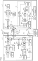
- FIG. 2 is a block diagram illustrating the configuration of an outdoor unit 2 and an indoor unit 3 according to the first embodiment.
- the air conditioning system according to the present embodiment includes multiple pieces of air conditioning-related equipment (hereinafter may also be referred to as multiple air conditioning-related units), such as a centralized management device 1, outdoor units 2, indoor units 3, and a refrigerant switching device 4.
- the multiple air conditioning-related units are connected via multiple types of wiring L.
- the air conditioning-related equipment is not limited to the above, and includes various types of equipment related to air conditioning, such as ventilation devices, remote controllers, communication devices, or control devices.
- the wiring L connecting the air conditioning-related equipment includes wiring L for transmitting high-voltage power along with communication (hereinafter referred to as a high-voltage power line L1), wiring L for transmitting low-voltage power along with communication (hereinafter referred to as a low-voltage power line L2), and wiring L dedicated to communication and not to power transmission (hereinafter referred to as a dedicated communication line).
- the high-voltage power line L1 is wiring L for transmitting power required to operate the drive system of a refrigerant circuit and the like.
- the low-voltage power line L2 is wiring L for transmitting power required to operate a control system, for example.
- multiple air conditioning-related units are connected by the high-voltage power line L1 and the low-voltage power line L2.
- the centralized management device 1 and the outdoor units 2 can communicate via the low-voltage power line L2.
- Multiple indoor units 3 are connected to a first outdoor unit 2 via the high-voltage power line L1.
- the outdoor unit 2 communicates with the indoor units 3 via the high-voltage power line L1, and supplies high-voltage power to the indoor units 3.
- the first outdoor unit 2 and the indoor units 3 form one system (for example, one refrigerant circuit).
- Multiple indoor units 3 are daisy-chained to a second outdoor unit 2 via the low-voltage power line L2.
- the second outdoor unit 2 and the indoor units 3 can communicate via the low-voltage power line L2.
- the second outdoor unit 2 and the indoor units 3 form one system.
- the refrigerant switching device 4 is connected to a third outdoor unit 2 via the low-voltage power line L2. Multiple indoor units 3 are daisy-chained to the refrigerant switching device 4 via the high-voltage power line L1.
- the third outdoor unit 2 and the refrigerant switching device 4 can communicate via the low-voltage power line L2.
- the refrigerant switching device 4 communicates with the indoor units 3 via the high-voltage power line L1, and supplies high-voltage power to the indoor units 3.
- the third outdoor unit 2 can communicate with the indoor units 3 via the low-voltage power line L2 and the high-voltage power line L1.
- the third outdoor unit 2, the refrigerant switching device 4, and the indoor units 3 form one system.
- connection circuits 20 and 30 are provided with isolation circuits 20b and 30b, and communication circuits 20d and 30d communicating using a certain common communication protocol, thereby realizing interoperable signal communication.
- "communication" in the outdoor units 2 and the indoor units 3 indicate the communication circuits 20d and 30d
- "isolation” indicates the isolation circuits 20b and 30b.
- the refrigerant switching device 4 also has the same or similar circuit configuration as the outdoor units 2, and realizes interoperable signal communication.
- signals pertaining to communication are transmitted through the shared line L12 connected to the reference potential and the signal line L13, signals pertaining to communication can be prevented from leaking to an external power system through the power line L13.
- the outdoor unit 2 includes a first connection portion 21 to which the high-voltage power line L1 is connected, a second connection portion 22 to which the low-voltage power line L2 or the dedicated communication line is connected, and a third connection portion 23 having a power terminal to which an AC power source 10 is connected.
- the outdoor unit 2 includes the connection circuit 20 connecting the first connection portion 21 and the second connection portion 22.
- the first connection portion 21 of the outdoor unit 2 includes receptacles to which the power line L11, the shared line L12, and the signal line L13 of the high-voltage power line L1 are connected.
- the first connection portion 21 includes two or more sets of receptacles for connecting to other air conditioning-related equipment in a daisy-chain configuration.
- the receptacles' corresponding terminals are connected. That is, a first receptacle includes a terminal to which the power line L11 of the high-voltage power line L1 is connected, a terminal to which the shared line L12 is connected, and a terminal to which the signal line L13 is connected.
- a second receptacle also includes a terminal to which the power line L11 of the high-voltage power line L1 is connected, a terminal to which the shared line L12 is connected, and a terminal to which the signal line L13 is connected.
- the receptacles' terminals to which the power line L11 is connected are connected.
- the receptacles' terminals to which the shared line L12 is connected are connected.
- the receptacles' terminals to which the signal line L13 is connected are connected.
- the second connection portion 22 of the outdoor unit 2 includes receptacles to which the low-voltage power line L2 or the dedicated communication line is connected.
- the second connection portion 22 includes two or more sets of receptacles for connecting to other air conditioning-related equipment in a daisy-chain configuration.
- the low-voltage power line L2 and the dedicated communication line each have two wires, and each receptacle includes terminals to which these two wires are connected. The receptacles' corresponding terminals are connected.
- the indoor unit 3 includes a first connection portion 31 to which the high-voltage power line L1 is connected, a second connection portion 32 to which the low-voltage power line L2 or the dedicated communication line is connected, and a third connection portion 33 to which the AC power source 10 is connected.
- the indoor unit 3 includes the connection circuit 30 connecting the first connection portion 31 and the second connection portion 32.
- the first connection portion 31 of the indoor unit 3 includes receptacles to which the power line L11, the shared line L12, and the signal line L13 of the high-voltage power line L1 are connected.
- the first connection portion 31 includes two or more sets of receptacles for connecting to other air conditioning-related equipment in a daisy-chain configuration.
- the second connection portion 32 of the indoor unit 3 includes receptacles to which the low-voltage power line L2 or the dedicated communication line is connected.
- the second connection portion 32 includes two or more sets of receptacles for connecting to other air conditioning-related equipment in a daisy-chain configuration.
- the low-voltage power line L2 and the dedicated communication line each have two wires, and each receptacle includes terminals to which these two wires are connected. The receptacles' corresponding terminals are connected.
- the first connection portion 21 of the outdoor unit 2 and the first connection portion 31 of the indoor unit 3 are connected via the high-voltage power line L1.
- the second connection portion 22 of the outdoor unit 2 and the centralized management device 1 are connected via the low-voltage power line L2.
- the AC power source 10 is connected to the third connection portion 23 of the outdoor unit 2.
- the wiring L and the AC power source 10 are not connected to the second connection portion 32 and the third connection portion 33 of the indoor unit 3.
- connection circuit 20 of outdoor unit 2 ⁇ Configuration of connection circuit 20 of outdoor unit 2>
- the connection circuit 20 of the outdoor unit 2 is a circuit that connects the first connection portion 21 and the second connection portion 22 of the outdoor unit 2.
- the connection circuit 20 includes a high-voltage noise filter (high-voltage NF) 20a, the isolation circuit 20b, a band-pass filter (BPF) 20c, the communication circuit 20d, a control circuit 20e, and a low-voltage noise filter (low-voltage NF) 20f.
- the connection circuit 20 further includes a first transmission circuit (high voltage PS) 20g and a second transmission circuit (PS) 20h for recognizing the system in the air conditioning system. The first transmission circuit 20g and the second transmission circuit 20h will be described in detail later.
- the communication circuit 20d is connected to the first connection portion 21 of the outdoor unit 2 via the high-voltage noise filter 20a, the isolation circuit 20b, and the band-pass filter 20c.
- internal wiring is connected to the terminals of the first connection portion 21 to which the shared line L12 and the signal line L13 of the high-voltage power line L1 are connected, and the first connection portion 21 and the communication circuit 20d are connected through the internal wiring.
- the high-voltage noise filter 20a is a circuit that removes noise that has entered the high-voltage power line L1.
- the high-voltage noise filter 20a is, for example, a common mode noise filter.
- the isolation circuit 20b is a circuit that blocks high-voltage power and transmits signals pertaining to communication.
- the isolation circuit 20b includes a transformer Tr1 and a capacitor C1 that are connected in series.
- the internal wiring connecting the high-voltage noise filter 20a and the communication circuit 20d is illustrated as a single line, but the circuits are connected by two lines of the internal wiring.
- Each of two terminals of a first coil constituting the transformer Tr1 is connected to the high-voltage noise filter 20a via the capacitor C1.
- Two terminals of a second coil constituting the transformer Tr1 are connected to the band-pass filter 20c.
- the band-pass filter 20c is a filter circuit that passes signal components transmitted and received between air conditioning-related units, while blocking non-signal components.
- the band-pass filter 20c may be a high-pass filter.
- isolation circuit 20b may be configured to include either the transformer Tr1 or the capacitor C1.
- the communication circuit 20d is connected to the second connection portion 22 of the outdoor unit 2 via the low-voltage noise filter 20f.
- internal wiring is connected to the terminal of the second connection portion 22, and the second connection portion 22 and the communication circuit 20d are connected through the internal wiring.
- the low-voltage noise filter 20f is a circuit that removes noise that has entered the low-voltage power line L2.
- the internal wiring connecting the second connection portion 22, the low-voltage noise filter 20f, and the communication circuit 20d is illustrated as a single line, but the circuits are connected by two lines of the internal wiring.
- the communication circuit 20d is, as described above, connected to the first connection portion 21 via the isolation circuit 20b, and is connected to the second connection portion 22 without the isolation circuit 20b interposed.
- the communication circuit 20d can communicate with external air conditioning-related equipment via the high-voltage power line L1 connected to the first connection portion 21, and can communicate with external air conditioning-related equipment via the low-voltage power line L2 or the dedicated communication line connected to the second connection portion 22.
- the communication circuit 20d can communicate with the indoor unit 3 via the high-voltage power line L1, and can communicate with the centralized management device 1 via the low-voltage power line L2.
- the control circuit 20e of the outdoor unit 2 is a circuit that controls the transmission and reception of signals by the communication circuit 20d and controls the operation of the outdoor unit 2.
- a control device includes an arithmetic processing unit that executes control programs, and a storage section.
- the arithmetic processing unit includes, for example, a CPU (Central Processing Unit) or an MPU (Micro Processing Unit).
- the storage section stores control programs and information used for control processing.
- the storage section includes a non-volatile memory and a volatile memory.
- connection circuit 30 of indoor unit 3 ⁇ Configuration of connection circuit 30 of indoor unit 3>
- the connection circuit 30 of the indoor unit 3 is a circuit connecting the first connection portion 31 and the second connection portion 32 of the indoor unit 3.
- the configuration of the connection circuit 30 of the indoor unit 3 is the same as or similar to the connection circuit 30 of the outdoor unit 2, and its detailed description will be omitted as appropriate.
- the connection circuit 30 includes a high-voltage noise filter (high-voltage NF) 30a, the isolation circuit 30b, a band-pass filter (BPF) 30c, the communication circuit 30d, a control circuit 30e, and a low-voltage noise filter (low-voltage NF) 30f.
- the connection circuit 30 further includes a first reception circuit (high-voltage PD) 30g and a second reception circuit (PD) 30h for recognizing the system in the air conditioning system. The first reception circuit 30g and the second reception circuit 30h will be described in detail later.
- the communication circuit 30d is connected to the first connection portion 31 of the indoor unit 3 via the high-voltage noise filter 30a, the isolation circuit 30b, and the band-pass filter 30c.
- internal wiring is connected to the terminals of the first connection portion 31 to which the shared line L12 and the signal line L13 of the high-voltage power line L1 are connected, and the first connection portion 31 and the communication circuit 30d are connected through the internal wiring.
- the isolation circuit 30b is a circuit that blocks high-voltage power and transmits signals pertaining to communication.
- the isolation circuit 30b includes a transformer Tr2 and a capacitor C2 that are connected in series. Each of two terminals of a first coil constituting the transformer Tr2 is connected to the high-voltage noise filter 30a via the capacitor C2. Two terminals of a second coil constituting the transformer Tr3 are connected to the band-pass filter 30c.
- the band-pass filter 30c is a filter circuit that passes signal components transmitted and received between air conditioning-related units, while blocking non-signal components.
- the communication circuit 30d is connected to the second connection portion 32 of the indoor unit 3 via the low-voltage noise filter 30f.
- internal wiring is connected to the terminal of the second connection portion 32, and the second connection portion 32 and the communication circuit 30d are connected through the internal wiring.
- the communication circuit 30d is, as described above, connected to the first connection portion 31 via the isolation circuit 30b, and is connected to the second connection portion 32 without the isolation circuit 30b interposed.
- the communication circuit 30d can communicate with external air conditioning-related equipment via the high-voltage power line L1 connected to the first connection portion 31, and can communicate with external air conditioning-related equipment via the low-voltage power line L2 or the dedicated communication line connected to the second connection portion 32.
- the communication circuit 30d can communicate with the outdoor unit 2 via the high-voltage power line L1.
- the control circuit 30e of the indoor unit 3 is a circuit that controls the transmission and reception of signals by the communication circuit 30d and controls the operation of the indoor unit 3.
- the storage section stores control programs and information used for control processing.
Landscapes
- Engineering & Computer Science (AREA)
- Chemical & Material Sciences (AREA)
- Combustion & Propulsion (AREA)
- Mechanical Engineering (AREA)
- General Engineering & Computer Science (AREA)
- Power Engineering (AREA)
- Computer Networks & Wireless Communication (AREA)
- Signal Processing (AREA)
- Human Computer Interaction (AREA)
- Air Conditioning Control Device (AREA)
- Cable Transmission Systems, Equalization Of Radio And Reduction Of Echo (AREA)
Abstract
Description
- The present disclosure relates to air conditioning-related equipment and an air conditioning system.
-
Patent Literature 1 discloses technology for connecting an outdoor unit and an indoor unit with a dedicated communication line and transmitting signals.Patent Literature 2 discloses an air conditioner that communicates using a power line and a communication line.Patent Literature 3 discloses a communication processing control circuit that can be used with both an alternating current (AC) power source and a direct current (DC) power source. -
- PTL 1:
Japanese Unexamined Patent Application Publication No. 2016-99020 - PTL 2: International Publication No.
2020/174563 - PTL 3:
Japanese Unexamined Patent Application Publication No. 2005-159921 - It is an object of the present disclosure to provide air conditioning-related equipment and an air conditioning system capable of interoperable signal communication with a communication network that includes wiring for transmitting high voltage along with communication, and a communication network that includes wiring dedicated to communication and not to power transmission or wiring for transmitting low voltage along with communication.
- Air conditioning-related equipment according to one aspect of the present disclosure includes: a first connection portion to which wiring for transmitting high voltage along with communication is connected; a second connection portion to which wiring dedicated to communication and not to power transmission or wiring for transmitting low voltage along with communication is connected; and a connection circuit that connects the first connection portion and the second connection portion, wherein the connection circuit includes an isolation circuit that blocks power transmission and transmits a signal pertaining to communication.
- In the air conditioning-related equipment according to this aspect of the present disclosure, preferably the connection circuit includes a communication circuit that communicates via the wiring for transmitting high voltage along with communication and communicates via the wiring dedicated to communication and not to power transmission or the wiring for transmitting low voltage along with communication, and the isolation circuit is provided in front of the communication circuit.
- In the air conditioning-related equipment according to this aspect of the present disclosure, preferably the isolation circuit is provided between the communication circuit and the first connection portion, and the second connection portion is connected to the communication circuit without the isolation circuit interposed.
- The air conditioning-related equipment according to this aspect of the present disclosure preferably includes: a power circuit that receives high-voltage power transmitted from external air conditioning-related equipment via the wiring for transmitting high voltage along with communication, or high-voltage power supplied from an alternating current power source, and supplies main power to the air conditioning-related equipment; and a power receiving circuit that receives low-voltage power transmitted from external air conditioning-related equipment via the wiring dedicated to communication and not to power transmission or the wiring for transmitting low voltage along with communication, and supplies auxiliary power to the air conditioning-related equipment.
- The air conditioning-related equipment according to this aspect of the present disclosure preferably includes: a first reception circuit that receives, via the wiring for transmitting high voltage along with communication, a signal at a lower frequency than a frequency of a signal pertaining to communication via the wiring for transmitting high voltage along with communication; and a second reception circuit that receives, via the wiring dedicated to communication and not to power transmission or the wiring for transmitting low voltage along with communication, a signal at a lower frequency than a frequency of a signal pertaining to communication via the wiring dedicated to communication and not to power transmission or the wiring for transmitting low voltage along with communication.
- The air conditioning-related equipment according to this aspect of the present disclosure preferably includes: a power circuit connected to an alternating current power source and supplying main power to the air conditioning-related equipment, wherein high-voltage power of the alternating current power source is transmitted to other air conditioning-related equipment via the wiring for transmitting high voltage along with communication.
- The air conditioning-related equipment according to this aspect of the present disclosure preferably includes: a first transmission circuit that transmits, via the wiring for transmitting high voltage along with communication, a signal at a lower frequency than a frequency of a signal pertaining to communication via the wiring for transmitting high voltage along with communication; and a second transmission circuit that transmits, via the wiring dedicated to communication and not to power transmission or the wiring for transmitting low voltage along with communication, a signal at a lower frequency than a frequency of a signal pertaining to communication via the wiring dedicated to communication and not to power transmission or the wiring for transmitting low voltage along with communication.
- In the air conditioning-related equipment according to this aspect of the present disclosure, preferably the wiring for transmitting high voltage along with communication includes a power line, a shared line, and a signal line; and high-voltage power is transmitted using the power line and the shared line, and the communication circuit communicates via the signal line and the shared line.
- In the air conditioning-related equipment according to this aspect of the present disclosure, preferably the isolation circuit includes a transformer and/or a capacitor.
- An air conditioning system according to one aspect of the present disclosure includes: first air conditioning-related equipment described above; and second air conditioning-related equipment connected to the first air conditioning-related equipment via the wiring for transmitting high voltage along with communication, the wiring dedicated to communication and not to power transmission, or the wiring for transmitting low voltage along with communication, wherein the first air conditioning-related equipment communicates with the second air conditioning-related equipment via the wiring for transmitting high voltage along with communication, the wiring dedicated to communication and not to power transmission, or the wiring for transmitting low voltage along with communication.
- An air conditioning system according to one aspect of the present disclosure includes: first air conditioning-related equipment described above; second air conditioning-related equipment connected to the first air conditioning-related equipment via the wiring for transmitting high voltage along with communication; and third air conditioning-related equipment connected to the first air conditioning-related equipment via the wiring dedicated to communication and not to power transmission or the wiring for transmitting low voltage along with communication, wherein the first air conditioning-related equipment communicates with the second air conditioning-related equipment via the wiring for transmitting high voltage along with communication, and communicates with the third air conditioning-related equipment via the wiring dedicated to communication and not to power transmission or the wiring for transmitting low voltage along with communication.
- According to the present disclosure, interoperable signal communication is enabled with a communication network that includes wiring for transmitting high voltage along with communication, and with a communication network that includes wiring dedicated to communication and not to power transmission or wiring for transmitting low voltage along with communication.
-
- [
FIG. 1] FIG. 1 is a block diagram illustrating the configuration of an air conditioning system according to a first embodiment. - [
FIG. 2] FIG. 2 is a block diagram illustrating the configuration of an outdoor unit and an indoor unit according to the first embodiment. - [
FIG. 3] FIG. 3 is a block diagram illustrating the configuration of the outdoor unit and the indoor unit according to the first embodiment. - [
FIG. 4] FIG. 4 is a block diagram illustrating the configuration of an air conditioning system according to a comparative example. - Air conditioning-related equipment and an air conditioning system according to an embodiment of the present disclosure will be described below with reference to the drawings.
-
FIG. 1 is a block diagram illustrating the configuration of an air conditioning system according to a first embodiment, andFIG. 2 is a block diagram illustrating the configuration of anoutdoor unit 2 and anindoor unit 3 according to the first embodiment. The air conditioning system according to the present embodiment includes multiple pieces of air conditioning-related equipment (hereinafter may also be referred to as multiple air conditioning-related units), such as acentralized management device 1,outdoor units 2,indoor units 3, and arefrigerant switching device 4. The multiple air conditioning-related units are connected via multiple types of wiring L. The air conditioning-related equipment is not limited to the above, and includes various types of equipment related to air conditioning, such as ventilation devices, remote controllers, communication devices, or control devices. - The wiring L connecting the air conditioning-related equipment includes wiring L for transmitting high-voltage power along with communication (hereinafter referred to as a high-voltage power line L1), wiring L for transmitting low-voltage power along with communication (hereinafter referred to as a low-voltage power line L2), and wiring L dedicated to communication and not to power transmission (hereinafter referred to as a dedicated communication line). The high-voltage power line L1 is wiring L for transmitting power required to operate the drive system of a refrigerant circuit and the like. The low-voltage power line L2 is wiring L for transmitting power required to operate a control system, for example. In the example illustrated in
FIG. 1 , multiple air conditioning-related units are connected by the high-voltage power line L1 and the low-voltage power line L2. - Multiple
outdoor units 2 are daisy-chained to thecentralized management device 1 via the low-voltage power line L2. Thecentralized management device 1 and theoutdoor units 2 can communicate via the low-voltage power line L2. - Multiple
indoor units 3 are connected to a firstoutdoor unit 2 via the high-voltage power line L1. Theoutdoor unit 2 communicates with theindoor units 3 via the high-voltage power line L1, and supplies high-voltage power to theindoor units 3. The firstoutdoor unit 2 and theindoor units 3 form one system (for example, one refrigerant circuit). - Multiple
indoor units 3 are daisy-chained to a secondoutdoor unit 2 via the low-voltage power line L2. The secondoutdoor unit 2 and theindoor units 3 can communicate via the low-voltage power line L2. The secondoutdoor unit 2 and theindoor units 3 form one system. - The
refrigerant switching device 4 is connected to a thirdoutdoor unit 2 via the low-voltage power line L2. Multipleindoor units 3 are daisy-chained to therefrigerant switching device 4 via the high-voltage power line L1. The thirdoutdoor unit 2 and therefrigerant switching device 4 can communicate via the low-voltage power line L2. Therefrigerant switching device 4 communicates with theindoor units 3 via the high-voltage power line L1, and supplies high-voltage power to theindoor units 3. The thirdoutdoor unit 2 can communicate with theindoor units 3 via the low-voltage power line L2 and the high-voltage power line L1. The thirdoutdoor unit 2, therefrigerant switching device 4, and theindoor units 3 form one system. - In the air conditioning system thus configured, the
outdoor units 2 and theindoor units 3 are provided withconnection circuits connection circuits isolation circuits communication circuits FIG. 1 , "communication" in theoutdoor units 2 and theindoor units 3 indicate thecommunication circuits isolation circuits refrigerant switching device 4 also has the same or similar circuit configuration as theoutdoor units 2, and realizes interoperable signal communication. - The functions of air conditioning-related equipment capable of interoperable signal communication are as follows.
- (1) The
outdoor units 2, theindoor units 3, and therefrigerant switching device 4 are capable of connecting to a communication network that utilizes the high-voltage power line L1, a communication network that utilizes the low-voltage power line L2, and a communication network that utilizes the dedicated communication line. - (2) The
outdoor units 2, theindoor units 3, and therefrigerant switching device 4 can be daisy-chained using different types of wiring L, and the individual air conditioning-related units can directly exchange signals through the multiple types of wiring L. The air conditioning-related equipment can communicate as if various types of air conditioning-related equipment were daisy-chained on the wiring L of the same system. Signals pertaining to communication are transmitted from the low-voltage power line L2 to the high-voltage power line L1, and from the high-voltage power line L1 to the low-voltage power line L2 via theisolation circuits isolation circuits - (3) The
outdoor units 2, theindoor units 3, and therefrigerant switching device 4 can communicate using a common communication protocol, regardless of the type and system of communication network. - The
outdoor unit 2 and theindoor unit 3 illustrated inFIG. 2 are connected via the high-voltage power line L1. The high-voltage power line L1 includes a power line L11, a shared line L12, and a signal line L13. The shared line L12 is, for example, an electric wire connected to a reference potential. For example, the shared line L12 is an electric wire grounded to 0 V. The power line L11 is an electric wire for transmitting high-voltage power. The signal line L13 is an electric wire for communication between air conditioning-related units. Theoutdoor unit 2 and theindoor unit 3 transmit high-voltage power using the power line L11 and the shared line L12, and communicate via the shared line L12 and the signal line L13. - Since signals pertaining to communication are transmitted through the shared line L12 connected to the reference potential and the signal line L13, signals pertaining to communication can be prevented from leaking to an external power system through the power line L13.
- The
outdoor unit 2 includes afirst connection portion 21 to which the high-voltage power line L1 is connected, asecond connection portion 22 to which the low-voltage power line L2 or the dedicated communication line is connected, and athird connection portion 23 having a power terminal to which anAC power source 10 is connected. Theoutdoor unit 2 includes theconnection circuit 20 connecting thefirst connection portion 21 and thesecond connection portion 22. - The
first connection portion 21 of theoutdoor unit 2 includes receptacles to which the power line L11, the shared line L12, and the signal line L13 of the high-voltage power line L1 are connected. Thefirst connection portion 21 includes two or more sets of receptacles for connecting to other air conditioning-related equipment in a daisy-chain configuration. The receptacles' corresponding terminals are connected. That is, a first receptacle includes a terminal to which the power line L11 of the high-voltage power line L1 is connected, a terminal to which the shared line L12 is connected, and a terminal to which the signal line L13 is connected. A second receptacle also includes a terminal to which the power line L11 of the high-voltage power line L1 is connected, a terminal to which the shared line L12 is connected, and a terminal to which the signal line L13 is connected. The receptacles' terminals to which the power line L11 is connected are connected. The receptacles' terminals to which the shared line L12 is connected are connected. The receptacles' terminals to which the signal line L13 is connected are connected. - The
second connection portion 22 of theoutdoor unit 2 includes receptacles to which the low-voltage power line L2 or the dedicated communication line is connected. Thesecond connection portion 22 includes two or more sets of receptacles for connecting to other air conditioning-related equipment in a daisy-chain configuration. The low-voltage power line L2 and the dedicated communication line each have two wires, and each receptacle includes terminals to which these two wires are connected. The receptacles' corresponding terminals are connected. - The
indoor unit 3 includes afirst connection portion 31 to which the high-voltage power line L1 is connected, asecond connection portion 32 to which the low-voltage power line L2 or the dedicated communication line is connected, and athird connection portion 33 to which theAC power source 10 is connected. Theindoor unit 3 includes theconnection circuit 30 connecting thefirst connection portion 31 and thesecond connection portion 32. - The
first connection portion 31 of theindoor unit 3 includes receptacles to which the power line L11, the shared line L12, and the signal line L13 of the high-voltage power line L1 are connected. Thefirst connection portion 31 includes two or more sets of receptacles for connecting to other air conditioning-related equipment in a daisy-chain configuration. - The
second connection portion 32 of theindoor unit 3 includes receptacles to which the low-voltage power line L2 or the dedicated communication line is connected. Thesecond connection portion 32 includes two or more sets of receptacles for connecting to other air conditioning-related equipment in a daisy-chain configuration. The low-voltage power line L2 and the dedicated communication line each have two wires, and each receptacle includes terminals to which these two wires are connected. The receptacles' corresponding terminals are connected. - In the example illustrated in
FIG. 2 , thefirst connection portion 21 of theoutdoor unit 2 and thefirst connection portion 31 of theindoor unit 3 are connected via the high-voltage power line L1. Thesecond connection portion 22 of theoutdoor unit 2 and thecentralized management device 1 are connected via the low-voltage power line L2. TheAC power source 10 is connected to thethird connection portion 23 of theoutdoor unit 2. The wiring L and theAC power source 10 are not connected to thesecond connection portion 32 and thethird connection portion 33 of theindoor unit 3. - The
connection circuit 20 of theoutdoor unit 2 is a circuit that connects thefirst connection portion 21 and thesecond connection portion 22 of theoutdoor unit 2. Theconnection circuit 20 includes a high-voltage noise filter (high-voltage NF) 20a, theisolation circuit 20b, a band-pass filter (BPF) 20c, thecommunication circuit 20d, acontrol circuit 20e, and a low-voltage noise filter (low-voltage NF) 20f. Theconnection circuit 20 further includes a first transmission circuit (high voltage PS) 20g and a second transmission circuit (PS) 20h for recognizing the system in the air conditioning system. Thefirst transmission circuit 20g and thesecond transmission circuit 20h will be described in detail later. - The
communication circuit 20d is connected to thefirst connection portion 21 of theoutdoor unit 2 via the high-voltage noise filter 20a, theisolation circuit 20b, and the band-pass filter 20c. In detail, internal wiring is connected to the terminals of thefirst connection portion 21 to which the shared line L12 and the signal line L13 of the high-voltage power line L1 are connected, and thefirst connection portion 21 and thecommunication circuit 20d are connected through the internal wiring. The high-voltage noise filter 20a is a circuit that removes noise that has entered the high-voltage power line L1. The high-voltage noise filter 20a is, for example, a common mode noise filter. Theisolation circuit 20b is a circuit that blocks high-voltage power and transmits signals pertaining to communication. Theisolation circuit 20b includes a transformer Tr1 and a capacitor C1 that are connected in series. For the convenience of drawing, the internal wiring connecting the high-voltage noise filter 20a and thecommunication circuit 20d is illustrated as a single line, but the circuits are connected by two lines of the internal wiring. Each of two terminals of a first coil constituting the transformer Tr1 is connected to the high-voltage noise filter 20a via the capacitor C1. Two terminals of a second coil constituting the transformer Tr1 are connected to the band-pass filter 20c. The band-pass filter 20c is a filter circuit that passes signal components transmitted and received between air conditioning-related units, while blocking non-signal components. For example, the band-pass filter 20c may be a high-pass filter. - Note that the
isolation circuit 20b may be configured to include either the transformer Tr1 or the capacitor C1. - The
communication circuit 20d is connected to thesecond connection portion 22 of theoutdoor unit 2 via the low-voltage noise filter 20f. In detail, internal wiring is connected to the terminal of thesecond connection portion 22, and thesecond connection portion 22 and thecommunication circuit 20d are connected through the internal wiring. The low-voltage noise filter 20f is a circuit that removes noise that has entered the low-voltage power line L2. For the convenience of drawing, the internal wiring connecting thesecond connection portion 22, the low-voltage noise filter 20f, and thecommunication circuit 20d is illustrated as a single line, but the circuits are connected by two lines of the internal wiring. - The
communication circuit 20d is, as described above, connected to thefirst connection portion 21 via theisolation circuit 20b, and is connected to thesecond connection portion 22 without theisolation circuit 20b interposed. Thecommunication circuit 20d can communicate with external air conditioning-related equipment via the high-voltage power line L1 connected to thefirst connection portion 21, and can communicate with external air conditioning-related equipment via the low-voltage power line L2 or the dedicated communication line connected to thesecond connection portion 22. In the example illustrated inFIG. 2 , thecommunication circuit 20d can communicate with theindoor unit 3 via the high-voltage power line L1, and can communicate with thecentralized management device 1 via the low-voltage power line L2. - The
control circuit 20e of theoutdoor unit 2 is a circuit that controls the transmission and reception of signals by thecommunication circuit 20d and controls the operation of theoutdoor unit 2. A control device includes an arithmetic processing unit that executes control programs, and a storage section. The arithmetic processing unit includes, for example, a CPU (Central Processing Unit) or an MPU (Micro Processing Unit). The storage section stores control programs and information used for control processing. The storage section includes a non-volatile memory and a volatile memory. - The
connection circuit 30 of theindoor unit 3 is a circuit connecting thefirst connection portion 31 and thesecond connection portion 32 of theindoor unit 3. The configuration of theconnection circuit 30 of theindoor unit 3 is the same as or similar to theconnection circuit 30 of theoutdoor unit 2, and its detailed description will be omitted as appropriate. Theconnection circuit 30 includes a high-voltage noise filter (high-voltage NF) 30a, theisolation circuit 30b, a band-pass filter (BPF) 30c, thecommunication circuit 30d, acontrol circuit 30e, and a low-voltage noise filter (low-voltage NF) 30f. Theconnection circuit 30 further includes a first reception circuit (high-voltage PD) 30g and a second reception circuit (PD) 30h for recognizing the system in the air conditioning system. Thefirst reception circuit 30g and thesecond reception circuit 30h will be described in detail later. - The
communication circuit 30d is connected to thefirst connection portion 31 of theindoor unit 3 via the high-voltage noise filter 30a, theisolation circuit 30b, and the band-pass filter 30c. In detail, internal wiring is connected to the terminals of thefirst connection portion 31 to which the shared line L12 and the signal line L13 of the high-voltage power line L1 are connected, and thefirst connection portion 31 and thecommunication circuit 30d are connected through the internal wiring. Theisolation circuit 30b is a circuit that blocks high-voltage power and transmits signals pertaining to communication. Theisolation circuit 30b includes a transformer Tr2 and a capacitor C2 that are connected in series. Each of two terminals of a first coil constituting the transformer Tr2 is connected to the high-voltage noise filter 30a via the capacitor C2. Two terminals of a second coil constituting the transformer Tr3 are connected to the band-pass filter 30c. The band-pass filter 30c is a filter circuit that passes signal components transmitted and received between air conditioning-related units, while blocking non-signal components. - The
communication circuit 30d is connected to thesecond connection portion 32 of theindoor unit 3 via the low-voltage noise filter 30f. In detail, internal wiring is connected to the terminal of thesecond connection portion 32, and thesecond connection portion 32 and thecommunication circuit 30d are connected through the internal wiring. - The
communication circuit 30d is, as described above, connected to thefirst connection portion 31 via theisolation circuit 30b, and is connected to thesecond connection portion 32 without theisolation circuit 30b interposed. Thecommunication circuit 30d can communicate with external air conditioning-related equipment via the high-voltage power line L1 connected to thefirst connection portion 31, and can communicate with external air conditioning-related equipment via the low-voltage power line L2 or the dedicated communication line connected to thesecond connection portion 32. In the example illustrated inFIG. 2 , thecommunication circuit 30d can communicate with theoutdoor unit 2 via the high-voltage power line L1. - The
control circuit 30e of theindoor unit 3 is a circuit that controls the transmission and reception of signals by thecommunication circuit 30d and controls the operation of theindoor unit 3. The storage section stores control programs and information used for control processing. - As described above, since the
outdoor units 2,indoor units 3, andrefrigerant switching devices 4, which belong to multiple systems, can communicate with each other interoperably, they are unable to recognize to which system the communicating and connected air conditioning-related equipment belongs through communication using thecommunication circuits - Accordingly, as circuits for recognizing the system, each
outdoor unit 2 according to the present embodiment includes thefirst transmission circuit 20g and thesecond transmission circuit 20h, and eachindoor unit 3 includes thefirst reception circuit 30g and thesecond reception circuit 30h. - The
first transmission circuit 20g of theoutdoor unit 2 is a circuit that transmits, via the high-voltage power line L1, a detection signal at a lower frequency than that of a signal pertaining to communication via the high-voltage power line L1. An output terminal of thefirst transmission circuit 20g is connected to thefirst connection portion 21. Specifically, thefirst transmission circuit 20g is connected to thefirst connection portion 21 via internal wiring connected to the shared line L12 and the signal line L13 of the high-voltage power line L1. An input terminal of thefirst transmission circuit 20g is connected to thecontrol circuit 20e. Thecontrol circuit 20e controls the operation of thefirst transmission circuit 20g. For example, thefirst transmission circuit 20g transmits a pulse signal encoded with the identifier of theoutdoor unit 2. - The
second transmission circuit 20h of theoutdoor unit 2 is a circuit that transmits, via the dedicated communication line or the low-voltage power line L2, a detection signal at a lower frequency than that of a signal pertaining to communication via the dedicated communication line or the low-voltage power line L2. An output terminal of thesecond transmission circuit 20h is connected to thesecond connection portion 22. An input terminal of thesecond transmission circuit 20h is connected to thecontrol circuit 20e. Thecontrol circuit 20e controls the signal transmission of thesecond transmission circuit 20h. For example, thesecond transmission circuit 20h transmits a pulse signal encoded with the identifier of theoutdoor unit 2. - The
first reception circuit 30g of theindoor unit 3 is a circuit that transmits, via the high-voltage power line L1, a detection signal at a lower frequency than that of a signal pertaining to communication via the high-voltage power line L1. An input terminal of thefirst reception circuit 30g is connected to thefirst connection portion 31. Specifically, thefirst reception circuit 30g is connected to thefirst connection portion 31 via internal wiring connected to the shared line L12 and the signal line L13 of the high-voltage power line L1. An output terminal of thefirst reception circuit 30g is connected to thecontrol circuit 30e. Thecontrol circuit 30e receives a detection signal via thefirst reception circuit 30g. Thecontrol circuit 30e can obtain the identifier of the transmission source by decoding the detection signal. - The
second reception circuit 30h of theindoor unit 3 is a circuit that transmits, via the dedicated communication line or the low-voltage power line L2, a detection signal at a lower frequency than that of a signal pertaining to communication via the dedicated communication line or the low-voltage power line L2. An input terminal of thesecond reception circuit 30h is connected to thesecond connection portion 32 via the low-voltage noise filter 30f. An output terminal of thesecond reception circuit 30h is connected to thecontrol circuit 30e. Thecontrol circuit 30e receives a detection signal via thesecond reception circuit 30h. Thecontrol circuit 30e can obtain the identifier of the transmission source by decoding the detection signal. - A high-frequency transmission filter is disposed between multiple systems that form the air conditioning system illustrated in
FIG. 1 . That is, a high-frequency transmission filter is provided in the wiring L connecting the air conditioning related equipment that forms a first system and the air conditioning related equipment that forms a second system. The high-frequency transmission filter is a filter circuit that passes signal components transmitted and received between air conditioning-related units, while blocking the above-described detection signals. By providing the high-frequency transmission filter, the transmission range of detected signals is limited to be within one system. - In the case where the
outdoor unit 2 is to recognize the system of air conditioning-related equipment connected to the high-voltage power line L1, thecontrol circuit 20e of theoutdoor unit 2 causes thefirst transmission circuit 20g to transmit a detection signal. The detection signal is at a lower frequency than signal components transmitted and received between air conditioning-related units, and does not pass through the high-frequency transmission filter. The detection signal only reaches the air conditioning-related equipment within the system defined by the high-frequency transmission filter. In the case where thecontrol circuit 30e of theindoor unit 3, which is daisy-chained to theoutdoor unit 2, receives a detection signal, transmitted from theoutdoor unit 2, at thefirst reception circuit 30g, a response signal is transmitted to theoutdoor unit 2 via the high-voltage power line L1. In the case where theoutdoor unit 2 receives the response signal at thecommunication circuit 20d, theoutdoor unit 2 recognizes that theoutdoor unit 2, which is the transmitting source of the response signal, is air conditioning-related equipment within the same system as itself. For other air conditioning-related equipment, the transmission and reception of a detection signal and a response signal enable the air conditioning-related equipment to recognize a group of air conditioning-related units within the same system. - In the case where the
outdoor unit 2 is to recognize the system of air conditioning-related equipment connected to the low-voltage power line L2 or the dedicated communication line, thecontrol circuit 20e of theoutdoor unit 2 causes thesecond transmission circuit 20h to transmit a detection signal. The detection signal only reaches the air conditioning-related equipment within the system defined by the high-frequency transmission filter. In the case where thecontrol circuit 30e of theindoor unit 3, which is daisy-chained to theoutdoor unit 2, receives the detection signal, transmitted from theoutdoor unit 2, at thesecond reception circuit 30h, a response signal is transmitted to theoutdoor unit 2 via the low-voltage power line L2 or the dedicated communication line. In the case where theoutdoor unit 2 receives the response signal at thecommunication circuit 20d, theoutdoor unit 2 recognizes that theoutdoor unit 2, which is the transmitting source of the response signal, is air conditioning-related equipment within the same system as itself. For other air conditioning-related equipment, the transmission and reception of a detection signal and a response signal enable the air conditioning-related equipment to recognize a group of air conditioning-related units within the same system. - The
outdoor unit 2 and theindoor unit 3 include an outdoor unit and an indoor unit, respectively, which form an unillustrated refrigerant circuit. The outdoor unit and the indoor unit are connected via a refrigerant pipe and a closing valve. The outdoor unit includes a compressor for inhaling, compressing, and discharging refrigerant, a four-way switching valve provided in the refrigerant pipe, an outdoor heat exchanger, an expansion mechanism for decompressing the refrigerant, and the like. The expansion mechanism is, for example, an expansion valve, a capillary tube, or the like. The indoor unit includes an indoor heat exchanger and the like. - The
outdoor unit 2 includes a noise filter (NF) 24, arectifier smoothing circuit 25, aninverter 26a, anoutdoor fan 26b, apower circuit 26c, and a low-pass filter (LPF) 27. - The
inverter 26a and theoutdoor fan 26b are connected to thethird connection portion 23 of theoutdoor unit 2 via thenoise filter 24 and therectifier smoothing circuit 25. Thenoise filter 24 removes noise that has occurred in theconnection circuits rectifier smoothing circuit 25 is a circuit that converts AC power supplied from theAC power source 10 or external air conditioning-related equipment to DC power. Theinverter 26a is a circuit that converts the DC power rectified by therectifier smoothing circuit 25 to AC power. The outdoor unit is driven by the AC power converted by theinverter 26a. Theoutdoor fan 26b is driven with the DC power rectified by therectifier smoothing circuit 25. Theoutdoor fan 26b blows air to the outdoor heat exchanger to facilitate heat exchange. - The
power circuit 26c is connected to thethird connection portion 23 of theoutdoor unit 2 via thenoise filter 24. Thepower circuit 26c is, for example, a switching power circuit. Thepower circuit 26c receives AC power supplied from theAC power source 10 or external air conditioning-related equipment and supplies main power to various units within theoutdoor unit 2, which is the unit itself. - The
third connection portion 23 of theoutdoor unit 2 is connected to thefirst connection portion 31 via the low-pass filter 27. The low-pass filter 27 blocks signals at higher frequencies than AC power and prevents such signals from leaking from thefirst connection portion 31 to the outside via thethird connection portion 33. In the case where theAC power source 10 is connected to thethird connection portion 33 and the high-voltage power line L1 is connected to thefirst connection portion 31, high-voltage power of theAC power source 10 is transmitted to external air conditioning-related equipment via thethird connection portion 33, thefirst connection portion 31, and the high-voltage power line L1. In the example illustrated inFIG. 2 , high-voltage power is transmitted from theoutdoor unit 2 to theindoor unit 3 via the high-voltage power line L1. - The
indoor unit 3 includes a noise filter (NF) 34, arectifier smoothing circuit 35, anindoor fan 36b, apower circuit 36c, low-pass filters (LPFs) 37 and 38, and apower receiving circuit 39. - The
indoor fan 36b is connected to thethird connection portion 33 of theindoor unit 3 via thenoise filter 34 and therectifier smoothing circuit 35. Thenoise filter 34 removes noise that has occurred in theconnection circuits rectifier smoothing circuit 35 is a circuit that converts AC power supplied from theAC power source 10 or external air conditioning-related equipment to DC power. Theindoor fan 36b is driven with the DC power rectified by therectifier smoothing circuit 35. Theindoor fan 36b blows air to the indoor heat exchanger and blows the heat-exchanged air into the indoor space. - The
power circuit 36c is connected to thethird connection portion 33 of theindoor unit 3 via thenoise filter 24. Thepower circuit 36c is, for example, a switching power circuit. Thepower circuit 36c receives AC power supplied from theAC power source 10 or external air conditioning-related equipment and supplies main power to various devices within theindoor unit 3 itself. - The
third connection portion 33 of theindoor unit 3 is connected to thefirst connection portion 31 via the low-pass filter 37. The low-pass filter 37 blocks signals at higher frequencies than AC power and prevents such signals from leaking from thefirst connection portion 31 to the outside via thethird connection portion 33. - The
power receiving circuit 39 is connected to thesecond connection portion 32 of theindoor unit 3 via the low-voltage noise filter 30f and the low-pass filter 38. The low-pass filter 38 is a circuit that removes signals pertaining to communication. Thepower receiving circuit 39 receives low-voltage power supplied from theoutdoor unit 2, therefrigerant switching device 4, or other air conditioning-related equipment via the low-voltage power line L2, and supplies auxiliary power to various circuits within theindoor unit 3 itself. - Although an example of providing the
indoor unit 3 with the low-pass filter 38 and thepower receiving circuit 39 for receiving low-voltage power has been described, theoutdoor unit 2 may also be provided with a circuit for receiving low-voltage power. -
FIG. 3 is a block diagram illustrating the configuration of theoutdoor unit 2 and theindoor unit 3 according to the first embodiment. Theoutdoor unit 2 and theindoor unit 3 have the same or similar configurations to those illustrated inFIG. 2 . In the example illustrated inFIG. 3 , thesecond connection portion 22 of theoutdoor unit 2 and thesecond connection portion 32 of theindoor unit 3 are connected via the low-voltage power line L2. Thesecond connection portion 22 of theoutdoor unit 2 and thecentralized management device 1 are connected via the low-voltage power line L2. TheAC power source 10 is connected to thethird connection portion 33 of theindoor unit 3 and thethird connection portion 23 of theoutdoor unit 2. No wiring L is connected to thefirst connection portion 21 of theoutdoor unit 2 and thefirst connection portion 31 of theindoor unit 3. - In the example illustrated in
FIG. 3 , theoutdoor unit 2 and theindoor unit 3 can transmit and receive signals via the low-voltage power line L2. Thecentralized management device 1 and theoutdoor unit 2 can transmit and receive signals via the low-voltage power line L2. Thecentralized management device 1 and theindoor unit 3 can transmit and receive signals via the low-voltage power line L2. - The
second connection portion 22 of theoutdoor unit 2 and thesecond connection portion 32 of theindoor unit 3 can be connected via the dedicated communication line. In this case, theoutdoor unit 2 and theindoor unit 3 can transmit and receive signals via the dedicated communication line. - The configuration pertaining to communication of the
refrigerant switching device 4 illustrated inFIG. 1 is the same as or similar to theoutdoor unit 2 or theindoor unit 3, and its detailed description is omitted. In the example illustrated inFIG. 1 , therefrigerant switching device 4 is connected to theoutdoor unit 2 via the low-voltage power line L2 and to theindoor units 3 via the high-voltage power line L1. Therefrigerant switching device 4 and theoutdoor unit 2 can transmit and receive signals via the low-voltage power line L2. Therefrigerant switching device 4 and theindoor units 3 can send and receive signals via the high-voltage power line L1. Theoutdoor unit 2 and theindoor units 3 can transmit and receive signals via low-voltage power and the high-voltage power line L1. Thecentralized management device 1 can transmit and receive signals via the low-voltage power line L2 and the high-voltage power line L1. -
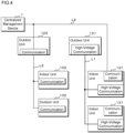
FIG. 4 is a block diagram illustrating the configuration of an air conditioning system according to a comparative example. The air conditioning system according to the comparative example is a system in which multiple air conditioning-related units are connected via multiple types of wiring L, but signals cannot be communicated interoperably. InFIG. 4 , "communication" indicates a dedicated high-voltage communication circuit for communicating via the low-voltage power line L2, and "high voltage communication" indicates a dedicated low-voltage communication circuit for communicating via the high-voltage power line L1. - An
outdoor unit 121 and multipleindoor units 131 according to the comparative example are connected via the high-voltage power line L1. Theoutdoor unit 121 and theindoor units 131 use the high-voltage communication circuits to transmit and receive signals using a dedicated high-voltage communication protocol. Theindoor units 131 each include the low-voltage communication circuit. One of theindoor units 131 communicates with thecentralized management device 1 using the low-voltage communication circuit via low-power power. Theindoor unit 131 and thecentralized management device 1 transmit and receive signals using a dedicated low-voltage communication protocol. Theindoor unit 131 can communicate via the low-voltage power line L2 and communicate via the high-voltage power line L1, but cannot communicate signals interoperably with the high-voltage power line L1 and the low-voltage power line L2, and their communication protocols are also different. Therefore, thecentralized management device 1 is unable to directly communicate with theoutdoor unit 121. Thecentralized management device 1 is also unable to directly communicate with theindoor unit 131 that is not connected via the low-voltage power line L2. - An
outdoor unit 122 and multipleindoor units 132 according to the comparative example are connected via the low-voltage power line L2. Theoutdoor unit 122 and theindoor units 132 use the low-voltage communication circuits to transmit and receive signals using a dedicated low-voltage communication protocol. Theoutdoor unit 122 is unable to directly communicate with theoutdoor unit 121. - As described above, the air conditioning system according to the comparative example is such that a communication network utilizing the high-voltage power line L1 and a communication network utilizing the low-voltage power line L2 are not connected to enable interoperable signal communication. Therefore, the equipment with which air conditioning-related equipment can communicate is limited.
- In contrast, according to the air conditioning system according to the present embodiment, a communication network utilizing the high-voltage power line L1 and a communication network utilizing the low-voltage power line L2 are connected to enable interoperable signal communication. The communication protocol is also standardized. Therefore, the individual air conditioning-related units can directly communicate across both the high-voltage power line L1 and the low-voltage power line L2.
- According to the air conditioning-related equipment and air conditioning system according to the present embodiment, the air conditioning-related equipment can be connected to enable interoperable signal communication with a communication network including the high-voltage power line L1 and a communication network including the low-voltage power line L2 or the dedicated communication line.
- The
connection circuits isolation circuits first connection portions second connection portions - The
communication circuits outdoor unit 2 and theindoor unit 3 are connected to the high-voltage power line L1 via theisolation circuits outdoor unit 2 and theindoor unit 3 can communicate via the high-voltage power line L1. - The
communication circuits outdoor unit 2 and theindoor unit 3 are connected to the low-voltage power line L2 without theisolation circuits outdoor unit 2 and theindoor unit 3 can communicate via the low-voltage power line L2. - The
outdoor units 2, theindoor units 3, and therefrigerant switching device 4 can receive high-voltage power supplied from other air conditioning-related equipment via the high-voltage power line L1 and operate. - The
outdoor units 2, theindoor units 3, and therefrigerant switching device 4 can receive low-voltage power supplied from other air conditioning-related equipment via the low-voltage power line L2 and operate. - The
outdoor units 2, theindoor units 3, and therefrigerant switching device 4 can supply high-voltage power to other air conditioning-related equipment via the high-voltage power line L1. - The
outdoor units 2 and theindoor units 3 can transmit and receive low-frequency signals for recognizing the system and recognize the system. That is, theoutdoor units 2 and theindoor units 3 can recognize air conditioning-related equipment within the same system as the system to which they are connected. - Since communication is performed in the high-frequency band, even if part of the communication path fails, air conditioning-related units that are successfully connected via the wiring L can continue to communicate in a relatively stable manner.
- Since high-speed communication is possible, the air conditioning-related equipment can transmit and receive information other than control data for the air conditioning system. For example, information pertaining to maintenance and inspection can be transmitted and received.
- Since the protocols for communication via the high-voltage power line L1, communication via the low-voltage power line L2, and communication via the dedicated communication line are standardized, the
communication circuits - The
isolation circuits - The air conditioning-related equipment can transmit and receive signals using the shared line L12, which is one of conductor wires for transmitting high-voltage power, and the signal line L13. The high-voltage power line L1 can be used as an electric wire for communication, and signals pertaining to communication can be prevented from leaking into the power system.
- Although the embodiment has been described above, it will be understood that various changes in form and details are possible without departing from the spirit and scope of the claims. Any part of the above embodiment may be optionally combined.
-
- 1
- centralized management device
- 2
- outdoor units
- 3
- indoor units
- 4
- refrigerant switching device
- 10
- AC power source
- 20
- connection circuit
- 20a
- high-voltage noise filter
- 20b
- isolation circuit
- 20c
- band-pass filter
- 20d
- communication circuit
- 20e
- control circuit
- 20f
- low-voltage noise filter
- 20g
- first transmission circuit
- 20h
- second transmission circuit
- 21
- first connection portion
- 22
- second connection portion
- 23
- third connection portion
- 24
- noise filter
- 25
- rectifier smoothing circuit
- 26a
- inverter
- 26b
- outdoor fan
- 26c
- power circuit
- 27
- low-pass filter
- 30
- connection circuit
- 30a
- high-voltage noise filter
- 30b
- isolation circuit
- 30c
- band-pass filter
- 30d
- communication circuit
- 30e
- control circuit
- 30f
- low-voltage noise filter
- 30g
- first reception circuit
- 30h
- second reception circuit
- 31
- first connection portion
- 32
- second connection portion
- 33
- third connection portion
- 34
- noise filter
- 35
- rectifier smoothing circuit
- 36b
- indoor fan
- 36c
- power circuit
- 37
- low-pass filter
- 38
- low-pass filter
- 39
- power receiving circuit
- C1
- capacitor
- C2
- capacitor
- L
- wiring
- L1
- high-voltage power line
- L11
- power line
- L12
- shared line
- L13
- signal line
- L2
- low-voltage power line
Claims (11)
- Air conditioning-related equipment comprising:a first connection portion to which wiring for transmitting high voltage along with communication is connected;a second connection portion to which wiring dedicated to communication and not to power transmission or wiring for transmitting low voltage along with communication is connected; anda connection circuit that connects the first connection portion and the second connection portion,wherein the connection circuit includes an isolation circuit that blocks power transmission and transmits a signal pertaining to communication.
- The air conditioning-related equipment according to claim 1, wherein:the connection circuit includesa communication circuit that communicates via the wiring for transmitting high voltage along with communication, and communicates via the wiring dedicated to communication and not to power transmission or the wiring for transmitting low voltage along with communication, andthe isolation circuit is provided in front of the communication circuit.
- The air conditioning-related equipment according to claim 2, wherein:
the isolation circuit is provided between the communication circuit and the first connection portion, and the second connection portion is connected to the communication circuit without the isolation circuit interposed. - The air conditioning-related equipment according to claim 2 or 3, comprising:a power circuit that receives high-voltage power transmitted from external air conditioning-related equipment via the wiring for transmitting high voltage along with communication, or high-voltage power supplied from an alternating current power source, and supplies main power to the air conditioning-related equipment; anda power receiving circuit that receives low-voltage power transmitted from external air conditioning-related equipment via the wiring dedicated to communication and not to power transmission or the wiring for transmitting low voltage along with communication, and supplies auxiliary power to the air conditioning-related equipment.
- The air conditioning-related equipment according to claim 4, comprising:a first reception circuit that receives, via the wiring for transmitting high voltage along with communication, a signal at a lower frequency than a frequency of a signal pertaining to communication via the wiring for transmitting high voltage along with communication; anda second reception circuit that receives, via the wiring dedicated to communication and not to power transmission or the wiring for transmitting low voltage along with communication, a signal at a lower frequency than a frequency of a signal pertaining to communication via the wiring dedicated to communication and not to power transmission or the wiring for transmitting low voltage along with communication.
- The air conditioning-related equipment according to claim 2 or 3, comprising:a power circuit connected to an alternating current power source and supplying main power to the air conditioning-related equipment,wherein high-voltage power of the alternating current power source is supplied to other air conditioning-related equipment via the wiring for transmitting high voltage along with communication.
- The air conditioning-related equipment according to claim 6, comprising:a first transmission circuit that transmits, via the wiring for transmitting high voltage along with communication, a signal at a lower frequency than a frequency of a signal pertaining to communication via the wiring for transmitting high voltage along with communication; anda second transmission circuit that transmits, via the wiring dedicated to communication and not to power transmission or the wiring for transmitting low voltage along with communication, a signal at a lower frequency than a frequency of a signal pertaining to communication via the wiring dedicated to communication and not to power transmission or the wiring for transmitting low voltage along with communication.
- The air conditioning-related equipment according to any one of claims 2 to 7, wherein:the wiring for transmitting high voltage along with communication includes a power line, a shared line, and a signal line, andhigh-voltage power is transmitted using the power line and the shared line, and the communication circuit communicates via the signal line and the shared line.
- The air conditioning-related equipment according to any one of claims 1 to 8, wherein:the isolation circuit includesa transformer or a capacitor.
- An air conditioning system comprising:first air conditioning-related equipment according to any one of claims 1 to 9; andsecond air conditioning-related equipment connected to the first air conditioning-related equipment via the wiring for transmitting high voltage along with communication, the wiring dedicated to communication and not to power transmission, or the wiring for transmitting low voltage along with communication,wherein the first air conditioning-related equipment communicates with the second air conditioning-related equipment via the wiring for transmitting high voltage along with communication, the wiring dedicated to communication and not to power transmission, or the wiring for transmitting low voltage along with communication.
- An air conditioning system comprising:first air conditioning-related equipment according to any one of claims 1 to 9; andsecond air conditioning-related equipment connected to the first air conditioning-related equipment via the wiring for transmitting high voltage along with communication; andthird air conditioning-related equipment connected to the first air conditioning-related equipment via the wiring dedicated to communication and not to power transmission or the wiring for transmitting low voltage along with communication,wherein the first air conditioning-related equipment communicates with the second air conditioning-related equipment via the wiring for transmitting high voltage along with communication, and communicates with the third air conditioning-related equipment via the wiring dedicated to communication and not to power transmission or the wiring for transmitting low voltage along with communication.
Applications Claiming Priority (2)
| Application Number | Priority Date | Filing Date | Title |
|---|---|---|---|
| JP2022061066A JP7385149B2 (en) | 2022-03-31 | 2022-03-31 | Air conditioning related equipment and air conditioning systems |
| PCT/JP2023/012718 WO2023190632A1 (en) | 2022-03-31 | 2023-03-29 | Air conditioning-related equipment and air conditioning system |
Publications (2)
| Publication Number | Publication Date |
|---|---|
| EP4503456A1 true EP4503456A1 (en) | 2025-02-05 |
| EP4503456A4 EP4503456A4 (en) | 2025-07-30 |
Family
ID=88201973
Family Applications (1)
| Application Number | Title | Priority Date | Filing Date |
|---|---|---|---|
| EP23780641.9A Pending EP4503456A4 (en) | 2022-03-31 | 2023-03-29 | EQUIPMENT ASSOCIATED WITH AIR CONDITIONING AND AIR CONDITIONING SYSTEM |
Country Status (5)
| Country | Link |
|---|---|
| US (1) | US12305877B2 (en) |
| EP (1) | EP4503456A4 (en) |
| JP (1) | JP7385149B2 (en) |
| CN (1) | CN119234395B (en) |
| WO (1) | WO2023190632A1 (en) |
Families Citing this family (2)
| Publication number | Priority date | Publication date | Assignee | Title |
|---|---|---|---|---|
| WO2025203473A1 (en) * | 2024-03-28 | 2025-10-02 | 三菱電機株式会社 | Ventilation control interface device |
| JP7902388B2 (en) * | 2024-06-18 | 2026-08-07 | 三菱電機株式会社 | Air conditioner, air conditioning system, and method for manufacturing an air conditioner |
Family Cites Families (17)
| Publication number | Priority date | Publication date | Assignee | Title |
|---|---|---|---|---|
| SG91835A1 (en) * | 1999-02-26 | 2002-10-15 | Lg Electronics Inc | Communication module and initialization method for multi-air conditioner system |
| JP2005020197A (en) | 2003-06-24 | 2005-01-20 | Hitachi Ltd | Power line communication device, control system, and method for setting connection wiring in power line communication device |
| JP2005159921A (en) | 2003-11-28 | 2005-06-16 | Yaskawa Electric Corp | Communication processing control circuit |
| JP3806882B2 (en) * | 2004-11-29 | 2006-08-09 | ダイキン工業株式会社 | Air conditioner |
| KR101587066B1 (en) * | 2010-08-05 | 2016-01-21 | 삼성전자 주식회사 | Air conditioner and communication method thereof |
| JP5528618B2 (en) | 2011-02-21 | 2014-06-25 | 三菱電機株式会社 | Air conditioning equipment and air conditioning system |
| JP5382105B2 (en) * | 2011-12-28 | 2014-01-08 | ダイキン工業株式会社 | Air conditioner |
| JP6345090B2 (en) | 2014-11-19 | 2018-06-20 | 日立ジョンソンコントロールズ空調株式会社 | Air conditioner |
| JP6692696B2 (en) | 2016-05-26 | 2020-05-13 | シャープ株式会社 | Air conditioner |
| CN107547109B (en) * | 2017-08-04 | 2021-05-25 | 广东美的制冷设备有限公司 | Air conditioner current loop communication circuit and air conditioner |
| JP6593402B2 (en) * | 2017-08-09 | 2019-10-23 | ダイキン工業株式会社 | Refrigeration unit outdoor unit |
| JP2019100655A (en) | 2017-12-06 | 2019-06-24 | シャープ株式会社 | Air conditioner, indoor unit and outdoor unit |
| EP3933290B1 (en) | 2019-02-26 | 2024-07-24 | Mitsubishi Electric Corporation | Electrical device |
| CN110994756A (en) * | 2019-11-29 | 2020-04-10 | 珠海格力电器股份有限公司 | Air conditioner power supply device and method and air conditioner |
| JP2022185182A (en) | 2021-06-02 | 2022-12-14 | ダイキン工業株式会社 | System component |
| JP2022185181A (en) | 2021-06-02 | 2022-12-14 | ダイキン工業株式会社 | Indoor machine |
| JP2023119900A (en) * | 2022-02-17 | 2023-08-29 | ダイキン工業株式会社 | air conditioner |
-
2022
- 2022-03-31 JP JP2022061066A patent/JP7385149B2/en active Active
-
2023
- 2023-03-29 CN CN202380032003.0A patent/CN119234395B/en active Active
- 2023-03-29 EP EP23780641.9A patent/EP4503456A4/en active Pending
- 2023-03-29 WO PCT/JP2023/012718 patent/WO2023190632A1/en not_active Ceased
- 2023-03-29 US US18/852,510 patent/US12305877B2/en active Active
Also Published As
| Publication number | Publication date |
|---|---|
| WO2023190632A1 (en) | 2023-10-05 |
| EP4503456A4 (en) | 2025-07-30 |
| CN119234395B (en) | 2025-12-02 |
| CN119234395A (en) | 2024-12-31 |
| US20250102181A1 (en) | 2025-03-27 |
| JP7385149B2 (en) | 2023-11-22 |
| US12305877B2 (en) | 2025-05-20 |
| JP2023151457A (en) | 2023-10-16 |
Similar Documents
| Publication | Publication Date | Title |
|---|---|---|
| US12305877B2 (en) | Air conditioning-related equipment and air conditioning system | |
| US9787362B2 (en) | Transmitter path for power line communication devices | |
| CA2589959C (en) | Hvac communication system | |
| US6710704B2 (en) | Power transfer apparatus for concurrently transmitting data and power over data wires | |
| EP2679925B1 (en) | Air conditioning apparatus and air conditioning system | |
| US7573372B2 (en) | Multiple channel ballast and networkable topology and system including power line carrier applications | |
| CN216897511U (en) | Slave line controller of multi-split air conditioner, multi-split air conditioner and multi-split air conditioner system | |
| US12467655B2 (en) | Indoor unit | |
| CN113300738B (en) | Cross-phase communicator, communication method, system and storage medium | |
| KR20110121187A (en) | Indoor DC power system with power line communication function | |
| RU2714858C2 (en) | Electric power meter and adapter module therefor | |
| JP7385148B2 (en) | Air conditioning related equipment and air conditioning systems | |
| WO2023238190A1 (en) | Air conditioning system | |
| CN206149267U (en) | Photovoltaic allies oneself with carrier communication coupling transmission circuit of air conditioner more | |
| CN210348229U (en) | Intelligent toll booth control system based on RS485 communication | |
| CN106656270A (en) | Photovoltaic multi-connected air conditioner carrier communication coupled transmission method and carrier communication coupled transmission circuit | |
| JP2005064750A (en) | Receiver for power line communication | |
| CN207720136U (en) | Termination power, collector and the system communicated based on two-phase, three-wire or phase three-wire three | |
| CN113676223A (en) | Power line carrier communication system and air conditioning system | |
| CN214335932U (en) | Communication cascade box of high-voltage UPS battery system | |
| KR100541480B1 (en) | Power line communication method of multi air conditioner | |
| JP2009079812A (en) | Air conditioning system and communication control device | |
| JPH05272795A (en) | Air conditioner | |
| CN207741274U (en) | Air-conditioning communication switching unit and air-conditioning communicate converting system | |
| JP2003264487A (en) | SS transmission system |
Legal Events
| Date | Code | Title | Description |
|---|---|---|---|
| STAA | Information on the status of an ep patent application or granted ep patent |
Free format text: STATUS: THE INTERNATIONAL PUBLICATION HAS BEEN MADE |
|
| PUAI | Public reference made under article 153(3) epc to a published international application that has entered the european phase |
Free format text: ORIGINAL CODE: 0009012 |
|
| STAA | Information on the status of an ep patent application or granted ep patent |
Free format text: STATUS: REQUEST FOR EXAMINATION WAS MADE |
|
| 17P | Request for examination filed |
Effective date: 20241017 |
|
| AK | Designated contracting states |
Kind code of ref document: A1 Designated state(s): AL AT BE BG CH CY CZ DE DK EE ES FI FR GB GR HR HU IE IS IT LI LT LU LV MC ME MK MT NL NO PL PT RO RS SE SI SK SM TR |
|
| DAV | Request for validation of the european patent (deleted) | ||
| DAX | Request for extension of the european patent (deleted) | ||
| A4 | Supplementary search report drawn up and despatched |
Effective date: 20250702 |
|
| RIC1 | Information provided on ipc code assigned before grant |
Ipc: H04B 3/54 20060101AFI20250626BHEP Ipc: F24F 11/88 20180101ALI20250626BHEP Ipc: F24F 11/50 20180101ALI20250626BHEP |
|
| P01 | Opt-out of the competence of the unified patent court (upc) registered |
Free format text: CASE NUMBER: UPC_APP_3799_4503456/2025 Effective date: 20250820 |