EP4503455A1 - Air-conditioning-related apparatus and air-conditioning system - Google Patents
Air-conditioning-related apparatus and air-conditioning system Download PDFInfo
- Publication number
- EP4503455A1 EP4503455A1 EP23780640.1A EP23780640A EP4503455A1 EP 4503455 A1 EP4503455 A1 EP 4503455A1 EP 23780640 A EP23780640 A EP 23780640A EP 4503455 A1 EP4503455 A1 EP 4503455A1
- Authority
- EP
- European Patent Office
- Prior art keywords
- power source
- communication
- circuit
- air conditioning
- voltage power
- Prior art date
- Legal status (The legal status is an assumption and is not a legal conclusion. Google has not performed a legal analysis and makes no representation as to the accuracy of the status listed.)
- Pending
Links
Images


Classifications
-
- F—MECHANICAL ENGINEERING; LIGHTING; HEATING; WEAPONS; BLASTING
- F24—HEATING; RANGES; VENTILATING
- F24F—AIR-CONDITIONING; AIR-HUMIDIFICATION; VENTILATION; USE OF AIR CURRENTS FOR SCREENING
- F24F11/00—Control or safety arrangements
- F24F11/88—Electrical aspects, e.g. circuits
-
- H—ELECTRICITY
- H04—ELECTRIC COMMUNICATION TECHNIQUE
- H04B—TRANSMISSION
- H04B3/00—Line transmission systems
- H04B3/54—Systems for transmission via power distribution lines
- H04B3/548—Systems for transmission via power distribution lines the power on the line being DC
-
- H—ELECTRICITY
- H04—ELECTRIC COMMUNICATION TECHNIQUE
- H04B—TRANSMISSION
- H04B2203/00—Indexing scheme relating to line transmission systems
- H04B2203/54—Aspects of powerline communications not already covered by H04B3/54 and its subgroups
- H04B2203/5404—Methods of transmitting or receiving signals via power distribution lines
- H04B2203/5416—Methods of transmitting or receiving signals via power distribution lines by adding signals to the wave form of the power source
-
- H—ELECTRICITY
- H04—ELECTRIC COMMUNICATION TECHNIQUE
- H04B—TRANSMISSION
- H04B2203/00—Indexing scheme relating to line transmission systems
- H04B2203/54—Aspects of powerline communications not already covered by H04B3/54 and its subgroups
- H04B2203/5429—Applications for powerline communications
- H04B2203/5445—Local network
-
- H—ELECTRICITY
- H04—ELECTRIC COMMUNICATION TECHNIQUE
- H04B—TRANSMISSION
- H04B2203/00—Indexing scheme relating to line transmission systems
- H04B2203/54—Aspects of powerline communications not already covered by H04B3/54 and its subgroups
- H04B2203/5429—Applications for powerline communications
- H04B2203/5458—Monitor sensor; Alarm systems
Definitions
- the present disclosure relates to air conditioning related equipment and an air conditioning system.
- PTL 1 discloses a technique to connect an outdoor unit to an indoor unit with a communication line for signal transmission.
- PTL 2 discloses an air conditioner that performs communication using an alternating-current power source line.
- PTL 3 discloses an air conditioner that supplies a direct-current power source to multiple indoor units connected to each other with a communication line.
- Air conditioning related equipment includes a communication circuit that is communicably connected via at least two of a communication line through which a communication signal is transmitted, a high-voltage power source line through which high-voltage power is transmitted, and a low-voltage power source line through which low-voltage power is transmitted.
- the air conditioning related equipment desirably includes a power source circuit that generates driving power of the communication circuit from the high-voltage power and a connection portion to which the communication line is connected.
- the communication circuit desirably is connected to the connection portion.
- the air conditioning related equipment desirably includes a connection portion to which the low-voltage power source line is connected, a power reception circuit that generates auxiliary power from the low-voltage power to supply the auxiliary power to the communication circuit when the high-voltage power is stopped, and an impedance upper that is disposed between the connection portion and the power reception circuit and that keeps impedance of the connection portion higher than impedance of the power reception circuit across a frequency band of the communication signal.
- the communication circuit is desirably connected to the connection portion.
- the air conditioning related equipment desirably includes a connection portion to which the high-voltage power source line is connected, a power source circuit that generates driving power of the communication circuit from the high-voltage power, an impedance upper that is disposed between the connection portion and the power source circuit and that keeps impedance of the connection portion higher than impedance of the power source circuit across a frequency band of the communication signal, and an insulation circuit that cuts off the high-voltage power and that transmits the communication signal.
- the communication circuit is desirably connected to the connection portion via the insulation circuit.
- the air conditioning related equipment desirably includes a connection portion to which the high-voltage power source line is connected, a power source connection portion to which a high-voltage power source is connected, a power source circuit that generates driving power of the communication circuit from the high-voltage power, an impedance upper that is disposed between the connection portion and the power source connection portion and that keeps impedance of the connection portion higher than impedance of the power source connection portion across a frequency band of the communication signal, and an insulation circuit that cuts off the high-voltage power and that transmits the communication signal.
- the communication circuit is desirably connected to the connection portion via the insulation circuit.
- the air conditioning related equipment desirably includes a first connection portion to which the communication circuit is connected and to which the communication line or the low-voltage power source line is connected, a second connection portion to which the high-voltage power source line is connected, a power source circuit that is connected to the second connection portion and that generates driving power of the communication circuit from the high-voltage power, an impedance upper that is disposed between the second connection portion and the power source circuit and that keeps impedance of the second connection portion higher than impedance of the power source circuit across a frequency band of the communication signal, and an insulation circuit that is disposed between the second connection portion and the communication circuit and that cuts off the high-voltage power and transmits the communication signal.
- the air conditioning related equipment desirably includes a power reception circuit that generates auxiliary power from the low-voltage power and that supplies the auxiliary power to the communication circuit when the high-voltage power is stopped, and an impedance upper that is disposed between the first connection portion and the power reception circuit and that keeps impedance of the first connection portion higher than impedance of the power reception circuit across the frequency band of the communication signal.
- the insulation circuit desirably includes a capacitor.
- the communication circuit desirably performs communication using multiple signals in a frequency division multiplex system.
- the communication circuit desirably performs communication using a signal of a frequency of 100 kHz or higher.
- the high-voltage power source line desirably includes a power source line, a common line, and a signal line.
- the high-voltage power is desirably transmitted through the power source line and the common line and the communication circuit desirably performs communication via the signal line and the common line.
- An air conditioning system desirably includes the first air conditioning related equipment described above and second air conditioning related equipment that is connected to the first air conditioning related equipment via the communication line.
- the first air conditioning related equipment desirably communicates with the second air conditioning related equipment via the communication line.
- An air conditioning system desirably includes the first air conditioning related equipment described above and second air conditioning related equipment that is connected to the first air conditioning related equipment via the low-voltage power source line.
- the first air conditioning related equipment desirably communicates with the second air conditioning related equipment via the low-voltage power source line.
- An air conditioning system desirably includes the first air conditioning related equipment described above and second air conditioning related equipment that is connected to the first air conditioning related equipment via the high-voltage power source line.
- the first air conditioning related equipment desirably communicates with the second air conditioning related equipment via the high-voltage power source line.
- An air conditioning system desirably includes the first air conditioning related equipment described above, second air conditioning related equipment that is connected to the first air conditioning related equipment via the high-voltage power source line, and third air conditioning related equipment that is connected to the first air conditioning related equipment via the low-voltage power source line.
- the first air conditioning related equipment desirably communicates with the second air conditioning related equipment via the high-voltage power source line and desirably communicates with the third air conditioning related equipment via the low-voltage power source line.
- the present disclosure it is possible to support at least two of communication via the communication line through which the communication signal is transmitted, communication via the high-voltage power source line through which the high-voltage power is transmitted, and communication via the low-voltage power source line through which the low-voltage power is transmitted.
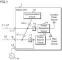
- Fig. 1 is a block diagram schematically illustrating the configuration of an indoor unit 1 according to a first embodiment.
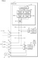
- Fig. 2 is a block diagram illustrating an example of the configuration of the indoor unit 1 according to the first embodiment.
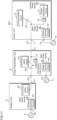
- Fig. 3A and Fig. 3B are circuit diagrams illustrating examples of the configurations of filter circuits.
- the indoor unit 1 according to the first embodiment is air conditioning related equipment capable of communicating with external air conditioning related equipment via one or two wiring lines of a communication line L1 through which a communication signal is transmitted, a high-voltage power source line L2 through which high-voltage power is transmitted, and a low-voltage power source line L3 through which low-voltage power is transmitted.
- a communication system in which pieces of air conditioning related equipment are connected with the communication line L1, the high-voltage power source line L2, or the low-voltage power source line L3 is referred to as an air conditioning system.
- the communication line L1 is a wiring line that is intended for transmission of the communication signal and that is not intended for power transmission.
- the communication line L1 includes two electric wires as transmission media of a differential signal.
- the communication line L1 is a two-core vinyl cabtire round cord (VCTF) .
- the high-voltage power source line L2 is a wiring line through which high-voltage power necessary to operate a driving system, such as a refrigerant circuit, is transmitted and through which the communication signal is transmitted.
- the high-voltage power source line L2 includes a power source line L21, a common line L22, and a signal line L23.
- the common line L22 is, for example, an electric wire connected to reference potential.
- the common line L22 is an electric wire grounded to 0 V.
- the power source line L21 is an electric wire for transmitting the high-voltage power.
- the signal line L23 is an electric wire for communication between the pieces of the air conditioning related equipment.
- the indoor unit 1 transmits the high-voltage power via the power source line L21 and the common line L22 and performs communication via the common line L22 and the signal line L23.
- the low-voltage power source line L3 is a wiring line through which power necessary to operate a control system is transmitted and through which the communication signal is transmitted.
- the low-voltage power source line L3 includes two electric wires as transmission media of the low-voltage power and the differential signal.
- the physical configuration of the low-voltage power source line L3 is the same as that of the communication line L1.
- the indoor unit 1 includes a communication circuit 10, a first connection portion 11, a second connection portion 12, a third connection portion 13, a power reception circuit 14, a first impedance upper 15, a power source circuit 16, and a second impedance upper 17.
- the first connection portion 11 is a connection terminal to which the communication line L1 or the low-voltage power source line L3 is connected.
- the first connection portion 11 is connected to the communication circuit 10 via a low-voltage cut-off capacitor C2.
- the first connection portion 11 is connected to the power reception circuit 14 via the first impedance upper 15.
- the first connection portion 11 includes two terminals 11a and 11b to which the two electric wires composing the low-voltage power source line L3 and the communication line L1 are respectively connected.
- Internal wiring lines are connected to the two terminals 11a and 11b, and the two terminals 11a and 11b are connected to a transmission circuit 10b and a reception circuit 10c via the capacitor C2 with the internal wiring lines.
- the internal wiring lines are connected to the two terminals 11a and 11b, and the terminals 11a and 11b are connected to the power reception circuit 14 via the first impedance upper 15 with the internal wiring lines.
- the first connection portion 21 may include two or more pairs of the terminals 11a and 11b for connection to other pieces of air conditioning related equipment in a daisy chain method.
- the corresponding terminals are connected to each other.
- the power reception circuit 14 is a circuit that receives the low-voltage power supplied from external air conditioning related equipment through the low-voltage power source line L3 and that supplies auxiliary power to various circuits in the indoor unit 1, which is the own unit.
- the power reception circuit 14 is capable of receiving the low-voltage power and supplying the received power to the communication circuit 10 even if supply of the high-voltage power is stopped.
- the first impedance upper 15 is a circuit that is disposed between the first connection portion 11 and the power reception circuit 14 and that keeps the impedance of the first connection portion 11 higher than the impedance of the power reception circuit 14 across a frequency band of the communication signal.
- the first impedance upper 15 is, for example, a low-pass filter and removes the communication signal and supplies only the low-voltage power to the power reception circuit 14.
- the second connection portion 12 is a connection terminal to which the high-voltage power source line L2 is connected.
- the second connection portion 12 is connected to the power source circuit 16 via the second impedance upper 17.
- the second connection portion 12 is connected to the communication circuit 10 via a high-voltage cut-off capacitor C1 (an insulation circuit) and the capacitor C2.
- the second connection portion 12 is connected to the first connection portion 11 via the capacitor C1.
- the second connection portion 12 includes a terminal 12a to which the power source line L21 of the high-voltage power source line L2 is connected, a terminal 12b to which the common line L22 is connected, and a terminal 12c to which the signal line L23 is connected.
- the terminal 12a and the terminal 12b are connected to the power source circuit 16 via the second impedance upper 17.
- the terminal 12b and the terminal 12c are connected to the capacitor C1.
- the second connection portion 22 may include two or more pairs of the terminals 12a, 12b, and 12c for connection to other pieces of air conditioning related equipment in the daisy chain method.
- the corresponding terminals are connected to each other.
- the second impedance upper 17 is a circuit that keeps the impedances of the terminals 12a and 12b higher than the impedance of the power source circuit 16 across the frequency band of the communication signal.
- the second impedance upper 17 is, for example, a low-pass filter circuit illustrated in Fig. 3B .
- the low-pass filter illustrated in Fig. 3B is an L-shaped filter circuit.
- the low-pass filter includes inductors L respectively connected in series to two communication paths and a capacitor C connected in parallel to the two communication paths.
- the capacitor C1 is a circuit that is disposed between the second connection portion 12, and the communication circuit 10 and the first connection portion 11 and that cuts off the high-voltage power and transmits the communication signal.
- the third connection portion 13 is a connection terminal to which an alternating-current power source A is connected.
- the third connection portion 13 includes two terminals 13a and 13b. Internal power source lines are connected to the two terminals 13a and 13b, and the terminals 13a and 13b are connected to the power source circuit 16 with the internal power source lines.
- the two terminals 13a and 13b are connected to the terminals 12a and 12b of the second connection portion 12 via the second impedance upper 17.
- a noise filter may be provided between the third connection portion 13 and the power source circuit 16.
- the power source circuit 16 is, for example, a switching power source circuit.
- the power source circuit 16 receives alternating-current power supplied from the alternating-current power source A or external air conditioning related equipment and supplies main power to various devices in the indoor unit 1, which is the own unit.
- the power source circuit 16 is a main power source and generates driving power for the communication circuit 10 to supply the generated driving power to the communication circuit 10.
- the communication circuit 10 is a circuit that performs frequency division multiplex communication.
- the communication circuit 10 includes a control circuit 10a, a transmission circuit 10b that transmits a signal modulated in the frequency division multiplex system in a band of 2 MHz to 28 MHz, and a reception circuit 10c that receives the signal modulated in the frequency division multiplex system in the same frequency band.
- the communication circuit 10 includes a transmission filter 18a, a reception filter 18b, and a noise filter 18.
- the communication circuit 10 is capable of broadband communication using a high frequency band and is capable of multicarrier communication using the signal in the frequency division multiplex system.
- the communication circuit 10 is capable of high-speed high-capacity communication.
- the following communication protocols are used in the communication circuit 10.
- a communication protocol in the frequency division multiplex system and the Ethernet are used as physical-datalink layers.
- User Datagram Protocol (UDP) is used as a transport layer protocol
- IPv6 Internet Protocol Version 6
- Constrained Application Protocol (CoAP) is used as an application protocol
- Concise Binary Object Representation (CBOR) is used as a serialization format.
- UDP is preferable for the indoor unit 1 and the air conditioning system according to the present embodiment. Since connection is not established, unlike Transmission Control Protocol (TPC), even when multiple pieces of air conditioning related equipment are connected, random access memories (RAMs) in the pieces of air conditioning related equipment are not overloaded.
- TPC Transmission Control Protocol
- RAMs random access memories
- IPv6 is preferable for the indoor unit 1 and the air conditioning system according to the present embodiment. Multiple pieces of air conditioning related equipment are capable of being identified with Internet protocol (IP) addresses having common specifications for communication.
- IP Internet protocol
- CoAP is preferable for the indoor unit 1 and the air conditioning system according to the present embodiment. Since binary communication is performed, light communication is enabled, compared with Hyper Text Transfer Protocol (HTTP). The correspondence between requests and responses is established and retransmission of data is enabled when the request fails. Acquisition and update of data concerning control, the operation state, and so on are capable of being performed between the pieces of air conditioning related equipment using a GET command and a SET command.
- HTTP Hyper Text Transfer Protocol
- CBOR is preferable for the indoor unit 1 and the air conditioning system according to the present embodiment. Since the binary communication is performed, light communication is enabled, compared with JavaScript Object Notation (JSON) or the like. Data is capable of being tagged to give meaning to data transmitted and received between the pieces of air conditioning related equipment.
- JSON JavaScript Object Notation
- a combination of the above protocols is most preferable for the indoor unit 1 and the air conditioning system according to the present embodiment.
- the transmission circuit 10b in the communication circuit 10 is connected to the second connection portion 12 via the transmission filter 18a, the noise filter 18, and the capacitors C1 and C2.
- the transmission circuit 10b is connected to the first connection portion 11 via the transmission filter 18a, the noise filter 18, and the capacitor C2.
- the reception circuit 10c in the communication circuit 10 is connected to the second connection portion 12 via the reception filter 18b, the noise filter 18, and the capacitors C1 and C2.
- the reception circuit 10c is connected to the first connection portion 11 via the reception filter 18b, the noise filter 18, and the capacitor C2.
- the communication circuit 10 is capable of communicating with external air conditioning related equipment via the high-voltage power source line L2 connected to the second connection portion 12 and is capable of communicating with external air conditioning related equipment via the communication line L1 or the low-voltage power source line L3 connected to the first connection portion 11.
- the noise filter 18 is a transformer that transmits the differential signal and that cuts off common mode noise. Both terminals of a first coil composing the transformer are respectively connected to the terminals 12b and 12c of the second connection portion 12 via the capacitors C1 and C2. Both terminals of the first coil are respectively connected to the terminals 11b and 11c of the first connection portion 11 via the capacitor C2. Both terminals of a second coil composing the noise filter 18 are connected to the transmission circuit 10b via the transmission filter 18a. Both terminals of the second coil composing the noise filter 18 are connected to the reception circuit 10c via the reception filter 18b.
- the transmission filter 18a and the reception filter 18b are filter circuits that transmit signal components transmitted and received between the pieces of air conditioning related equipment and that cut off non-signal components.
- the transmission filter 18a and the reception filter 18b are each desirably configured as a high-pass filter illustrated in Fig. 3A .
- the high-pass filter illustrated in Fig. 3A is a T-shaped filter circuit.
- the high-pass filter includes two capacitors C connected in series to a first communication path, two capacitors C connected in series to a second communication circuit, and an inductor L connected in parallel between nodes of the capacitors C on the respective paths.
- the transmission filter 18a and the reception filter 18b may be bandpass filter circuits.
- the control circuit 10a is a circuit that controls transmission and reception of the signals by the transmission circuit 10b and the reception circuit 10c to control the operation of the indoor unit 1.
- the control apparatus includes an arithmetic processing unit that executes control programs and a storage unit.
- the arithmetic processing unit includes, for example, a central processing unit (CPU) or a micro processing unit (MPU).
- the storage unit stores information used for the control programs and a control process.
- the storage unit includes a non-volatile memory and a volatile memory.
- the indoor unit 1 and an outdoor unit 2 each include an indoor unit composing a refrigerant circuit (not illustrated) and an outdoor unit.
- the indoor unit and the outdoor unit are connected to each other via a refrigerant pipe and a shutoff valve.
- the outdoor unit includes a compressor that sucks in and compresses refrigerant to discharge the refrigerant, a four-way switching valve provided in the refrigerant pipe, an outdoor heat exchanger, an expansion mechanism that decompresses the refrigerant, and so on.
- the expansion mechanism is, for example, an expansion valve, a capillary tube, or the like.
- the indoor unit includes an indoor heat exchanger and so on.
- Fig. 4 is a schematic diagram illustrating a first connection example of the indoor unit 1 and the outdoor unit 2 according to the first embodiment.
- the outdoor unit 2 includes a communication circuit 20, a first connection portion 21, a third connection portion 23, and a power source circuit 26.
- the first connection portion 21 is a connection terminal to which the communication line L1 is connected.
- the first connection portion 21 is connected to the communication circuit 20.
- the communication circuit 20 is a circuit that performs the frequency division multiplex communication.
- the configuration of the communication circuit 20 is the same as that of the communication circuit 10 in the indoor unit 1, and the communication circuit 20 is capable of communication using the same communication protocol as that of the communication circuit 10.
- the third connection portion 23 is a connection terminal to which the alternating-current power source A is connected.
- the third connection portion 23 is connected to the power source circuit 26.
- the power source circuit 26 receives the alternating-current power supplied from the alternating-current power source A connected to the third connection portion 23 and supplies the main power to various devices in the outdoor unit 2, which is
- the indoor unit 1 is capable of being connected to the outdoor unit 2 via the communication line L1 and is capable of transmitting and receiving the signal via the communication line L1.
- one end of the communication line L1 is connected to the first connection portion 11 of the indoor unit 1 and the other end of the communication line L1 is connected to the first connection portion 21 of the outdoor unit 2.
- the communication signal transmitted by the communication circuit 10 is transmitted to the outdoor unit 2 through the capacitor C2, the first connection portion 11, and the communication line L1.
- the communication signal transmitted from the outdoor unit 2 through the communication line L1 is input into the communication circuit 10 through the first connection portion 11 and the capacitor C2.
- Fig. 5 is a schematic diagram illustrating a second connection example of the indoor unit 1 and an outdoor unit 3 according to the first embodiment.
- the outdoor unit 3 includes a communication circuit 30, a second connection portion 32, a third connection portion 33, a power source circuit 36, an impedance upper 37, and an insulation circuit 38.
- the second connection portion 32 is a connection terminal to which the high-voltage power source line L2 is connected.
- the second connection portion 32 is connected to the communication circuit 30 via the insulation circuit 38.
- the second connection portion 32 is connected to the third connection portion 33 and the power source circuit 36 via the impedance upper 37.
- the communication circuit 30 is a circuit that performs the frequency division multiplex communication.
- the configuration of the communication circuit 30 is the same as that of the communication circuit 10 in the indoor unit 1, and the communication circuit 30 is capable of communication using the same communication protocol as that of the communication circuit 10.
- the third connection portion 33 is a connection terminal to which the alternating-current power source A is connected.
- the third connection portion 33 is connected to the power source circuit 36.
- the power source circuit 36 receives the alternating-current power supplied from the alternating-current power source A connected to the third connection portion 33 and supplies the main power to various devices in the outdoor unit 3, which is the own unit.
- the indoor unit 1 is capable of being connected to the outdoor unit 3 via the high-voltage power source line L2 and is capable of transmitting and receiving the signal via the high-voltage power source line L2.
- one end of the high-voltage power source line L2 is connected to the second connection portion 12 of the indoor unit 1 and the other end of the high-voltage power source line L2 is connected to the second connection portion 32 of the outdoor unit 3.
- the communication signal transmitted by the communication circuit 10 is transmitted to the outdoor unit 3 through the capacitors C1 and C2, the second connection portion 12, and the high-voltage power source line L2.
- the communication signal transmitted from the outdoor unit 3 through the high-voltage power source line L2 is input into the communication circuit 10 through the second connection portion 12 and the capacitors C1 and C2.
- the outdoor unit 3 supplies the high-voltage power to the indoor unit 1 via the high-voltage power source line L2.
- the high-voltage power supplied from the outdoor unit 3 through the high-voltage power source line L2 is input into the power source circuit 16 from the second connection portion 12 of the indoor unit 1 through the second impedance upper 17.
- the indoor unit 1 is capable of receiving the high-voltage power supplied from the outdoor unit 3.
- Fig. 6 is a schematic diagram illustrating a third connection example of the indoor unit 1 and the outdoor unit 2 according to the first embodiment.
- the indoor unit 1 is connected to the outdoor unit 2 via a power transmission unit 4.
- the outdoor unit 2 includes the communication circuit 20, the first connection portion 21, the third connection portion 23, and the power source circuit 26.
- This circuit configuration is the same as or similar to the circuit configuration of the outdoor unit 2 described above with reference to Fig. 4 .
- the power transmission unit 4 is a unit that supplies the low-voltage power.
- the power transmission unit 4 includes a communication circuit 40, a first connection portion 41, a second connection portion 42, a third connection portion 43, a power source circuit 46, an impedance upper 47, and a capacitor 49.
- the first connection portion 41 and the second connection portion 42 are connection terminals to which the low-voltage power source line L3 is connected.
- the first connection portion 41 is connected to the communication circuit 40.
- the second connection portion 42 is connected to the communication circuit 40 via the capacitor 49.
- the communication circuit 40 is connected to the first connection portion 41 and the second connection portion 42 in the daisy chain method.
- the power transmission unit 4 includes a low-voltage supplying power source circuit that supplies the low-voltage power.
- the low-voltage supplying power source circuit is connected to the first connection portion 41 via the impedance upper 47.
- the low-voltage supplying power source circuit supplies the low-voltage power to the low-voltage power source line L3 connected to the first connection portion 41.
- the third connection portion 43 is a connection terminal to which the alternating-current power source A is connected.
- the third connection portion 43 is connected to the power source circuit 46.
- the power source circuit 46 receives the alternating-current power supplied from the alternating-current power source A connected to the third connection portion 43 and supplies the main power to various devices in the power transmission unit 4, which is the own unit.
- the indoor unit 1 is capable of being connected to the outdoor unit 2 via the low-voltage power source line L3 and is capable of transmitting and receiving the signal via the low-voltage power source line L3.
- one end of a first low-voltage power source line L3 is connected to the first connection portion 11 of the indoor unit 1 and the other end of the low-voltage power source line L3 is connected to the first connection portion 41 of the power transmission unit 4.
- One end of a second low-voltage power source line L3 is connected to the second connection portion 42 of the power transmission unit 4 and the other end of the low-voltage power source line L3 is connected to the first connection portion 21 of the outdoor unit 2.
- the communication signal transmitted by the communication circuit 10 is transmitted to the outdoor unit 2 through the capacitor C2, the first connection portion 11, the first low-voltage power source line L3, the power transmission unit 4, and the second low-voltage power source line L3.
- the communication signal transmitted from the outdoor unit 2 through the communication line L1 is input into the communication circuit 10 through the first connection portion 11 and the capacitor C2.
- the low-voltage power supplied from the power transmission unit 4 through the low-voltage power source line L3 is input into the power reception circuit 14 from the first connection portion 11 of the indoor unit 1 through the first impedance upper 15.
- the indoor unit 1 is capable of receiving the low-voltage power with the power reception circuit 14.
- Fig. 7 is a schematic diagram illustrating a fourth connection example of the indoor unit 1 and the outdoor units 2 and 3 according to the first embodiment.
- the indoor unit 1 is connected to the outdoor unit 3 via the high-voltage power source line L2 and is connected to the outdoor unit 2 via the low-voltage power source line L3.
- the configuration of the outdoor unit 3 illustrated in Fig. 7 is the same as or similar to that of the outdoor unit 3 illustrated in Fig. 5 .
- the configurations of the outdoor unit 2 and the power transmission unit 4 illustrated in Fig. 7 are the same as or similar to the configurations of the outdoor unit 2 and the power transmission unit 4 illustrated in Fig. 6 .
- One end of the high-voltage power source line L2 is connected to the second connection portion 12 of the indoor unit 1 and the other end of the high-voltage power source line L2 is connected to the second connection portion 32 of the outdoor unit 3.
- One end of the first low-voltage power source line L3 is connected to the first connection portion 11 of the indoor unit 1 and the other end of the low-voltage power source line L3 is connected to the first connection portion 41 of the power transmission unit 4.
- One end of the second low-voltage power source line L3 is connected to the second connection portion 42 of the power transmission unit 4 and the other end of the low-voltage power source line L3 is connected to the first connection portion 21 of the outdoor unit 2.
- the indoor unit 1 is capable of being connected to the outdoor unit 3 via the high-voltage power source line L2 and is capable of being connected to the outdoor unit 2 via the low-voltage power source line L3.
- the indoor unit 1 is capable of communicating with the outdoor unit 2 via the low-voltage power source line L3 and is capable of communicating with the outdoor unit 3 via the high-voltage power source line L2.
- the indoor unit 1 realizes mutual communication of the signals with the high-voltage power source line L2 and the low-voltage power source line L3 through the provision of the capacitor C1 according to the present embodiment. Specifically, the indoor unit 1 realizes the mutual communication of the signals through the provision of the capacitor C1 and the communication circuits 10, 20, and 30, which communicate with each other with a common communication protocol using the frequency division multiplex communication method.
- the indoor unit 1 is capable of being connected to all of the communication line L1, the high-voltage power source line L2, and the low-voltage power source line L3 to communicate with external air conditioning related equipment.
- the indoor unit 1 Since the communication circuit 10 in the indoor unit 1 is connected to the high-voltage power source line L2 via the high-voltage cut-off capacitor C1, the indoor unit 1 is capable of communication via the high-voltage power source line L2.
- the communication circuit 10 in the indoor unit 1 is connected to the low-voltage power source line L3 not via the high-voltage cut-off capacitor C1 but via the low-voltage cut-off capacitor C2.
- the indoor unit 1 is capable of communication via the low-voltage power source line L3.
- the indoor unit 1 is capable of receiving the high-voltage power supplied from another piece of air conditioning related equipment via the high-voltage power source line L2 for operation.
- the indoor unit 1 is capable of receiving the low-voltage power supplied from another piece of air conditioning related equipment via the low-voltage power source line L3 for operation.
- the indoor unit 1 is capable of supplying the high-voltage power to another piece of air conditioning related equipment via the high-voltage power source line L2.
- the indoor unit 1 is capable of being connected to a communication network including the high-voltage power source line L2 and a communication network including the low-voltage power source line L3 or the communication line L1 so as to enable the mutual communication of the signals.
- the indoor unit 1 includes the high-voltage cut-off capacitor C1 provided between the first connection portion 11 to which the communication line L1 or the low-voltage power source line L3 is connected and the second connection portion 12 to which the high-voltage power source line L2 is connected, the mutual communication of the signals with the high-voltage power source line L2 and the low-voltage power source line L3 is enabled.
- the communication circuits 10 in the indoor unit 1 and the outdoor unit 2 are capable of performing the frequency division multiplex communication.
- the broadband communication and the multicarrier communication of the signal in the frequency division multiplex system are enabled in the high-frequency band of 2 MHz to 28 MHz.
- the indoor unit 1 and the outdoor unit 2 are capable of performing the high-speed high-capacity communication.
- the pieces of air conditioning related equipment that are normally connected to each other via the wiring lines are capable of relatively stably continuing the communication even if any failure occurs on part of the communication paths.
- the air conditioning related equipment is capable of transmitting and receiving information other than control data about the air conditioning system.
- the air conditioning related equipment is capable of transmitting and receiving information about maintenance and inspection.
- the communication circuit 10 in the indoor unit 1 and the communication circuit 20 in the outdoor unit 2 are capable of communicating with the pieces of air conditioning related equipment that are mutually connected using a common communication protocol.
- the high-voltage cut-off insulation circuit is capable of being configured by the simple circuit composed of the capacitor C1.
- the air conditioning related equipment is capable of transmitting and receiving the signal using the common line L22, which is one lead wire for transmitting the high-voltage power, and the signal line L23.
- the air conditioning related equipment is capable of using the high-voltage power source line L2 as an electric wire for communication.
- the indoor unit 1 is exemplified as the air conditioning related equipment according to the first embodiment
- the first embodiment may be applied to various devices concerning the air conditioning, such as the outdoor unit 2, a refrigerant switching apparatus, a power transmission unit, a ventilation apparatus, a remote controller, a communication apparatus, and a control apparatus.
- Fig. 8 is a block diagram illustrating an example of the configuration of an outdoor unit 202 according to a second embodiment.
- the outdoor unit 202 according to the second embodiment includes the communication circuit 20, the first connection portion 21, a second connection portion 22, the third connection portion 23, a power reception circuit 24, a first impedance upper 25, the power source circuit 26, and a second impedance upper 27. Since the circuit configuration concerning the communication and the power transmission is the same as the circuit configuration of the indoor unit 1, a detailed description of the circuit configuration of the outdoor unit 202 is appropriately omitted herein.
- the first connection portion 21 is a connection terminal to which the communication line L1 or the low-voltage power source line L3 is connected.
- the first connection portion 21 includes two terminals 21a and 21b to which the two electric wires composing the low-voltage power source line L3 and the communication line L1 are respectively connected.
- the first connection portion 21 is connected to the communication circuit 20 via a low-voltage cut-off capacitor C4.
- the first connection portion 21 is connected to the power reception circuit 24 via the first impedance upper 25.
- the power reception circuit 24 is a circuit that receives the low-voltage power supplied from external air conditioning related equipment via the low-voltage power source line L3 and that supplies the auxiliary power to various circuits in the outdoor unit 202, which is the own unit.
- the first impedance upper 25 is a circuit that is disposed between the first connection portion 21 and the power reception circuit 24 and that keeps the impedance of the first connection portion 21 higher than the impedance of the power reception circuit 24 across the frequency band of the communication signal.
- the second connection portion 22 is a connection terminal to which the high-voltage power source line L2 is connected.
- the second connection portion 22 is connected to the power source circuit 26 via the second impedance upper 27.
- the second connection portion 22 is connected to the communication circuit 20 via a high-voltage cut-off capacitor C3 (an insulation circuit) and the low-voltage cut-off capacitor C4.
- the second connection portion 22 includes a terminal 22a to which the power source line L21 of the high-voltage power source line L2 is connected, a terminal 22b to which the common line L22 is connected, and a terminal 22c to which the signal line L23 is connected.
- the terminals 22a and 22b are connected to the power source circuit 26 via the second impedance upper 27.
- the terminals 22b and 22c are connected to the high-voltage cut-off capacitor C3.
- the second impedance upper 27 is a circuit that keeps the impedances of the terminals 22a and 22b higher than the impedance of the power source circuit 26 across the frequency band of the communication signal.
- the capacitor C3 is a circuit that is disposed between the second connection portion 22, and the communication circuit 20 and the first connection portion 21 and that cuts off the high-voltage power and transmits the communication signal.
- the third connection portion 23 is a connection terminal to which the alternating-current power source A is connected.
- the third connection portion 23 includes two terminals 23a and 23b. Internal power source lines are connected to the two terminals 23a and 23b, and the terminals 23a and 23b are connected to the power source circuit 26 with the internal power source lines.
- the two terminals 23a and 23b are connected to the terminals 22a and 22b of the second connection portion 22 via the second impedance upper 27.
- the power source circuit 26 receives the alternating-current power supplied from the alternating-current power source A or external air conditioning related equipment and supplies the main power to various devices in the outdoor unit 202, which is the own unit.
- the communication circuit 20 includes a control circuit 20a, a transmission circuit 20b, a reception circuit 20c, a transmission filter 28a, a reception filter 28b, and a noise filter 28.
- the transmission circuit 20b, the reception circuit 20c, the transmission filter 28a, the reception filter 28b, and the noise filter 28 perform the frequency division multiplex communication.
- the configurations of the respective circuits and filters are the same as those of the circuits and filters in the indoor unit 1 of the first embodiment.
- the communication circuit 20 is connected to the second connection portion 22 via the capacitors C3 and C4.
- the communication circuit 20 is connected to the first connection portion 21 via the capacitor C4.
- the communication circuit 20 is capable of communicating with external air conditioning related equipment via the high-voltage power source line L2 connected to the second connection portion 22 and is capable of communicating with external air conditioning related equipment via the communication line L1 or the low-voltage power source line L3, which is connected to the first connection portion 21.
- the outdoor unit 202 is capable of being connected to all of the communication line L1, the high-voltage power source line L2, and the low-voltage power source line L3 to communicate with external air conditioning related equipment.
- Fig. 9 is a schematic diagram illustrating an example of the configuration of an indoor unit 301 and the outdoor unit 2 according to a third embodiment.
- the common communication protocol is used for the communication via the communication line L1, the communication via the high-voltage power source line L2, and the communication via the low-voltage power source line L3. Accordingly, providing one communication circuit 10 commonly used for multiple kinds of air conditioning related equipment and appropriately selecting necessary peripheral circuits enable the indoor unit 301 that performs communication only via the communication line L1 to be configured. Since the detailed configuration of the circuits composing the indoor unit 301 is the same as or similar to that in the first embodiment, a detailed description of the circuits composing the indoor unit 301 is omitted herein.
- the indoor unit 301 includes the communication circuit 10, the first connection portion 11, the third connection portion 13, and the power source circuit 16.
- the configuration of the outdoor unit 2 is the same as or similar to the circuit configuration of the outdoor unit 2 described above with reference to Fig. 4 .
- the first connection portion 11 of the indoor unit 301 is connected to the first connection portion 21 of the outdoor unit 2 via the communication line L1.
- the indoor unit 301 is capable of communicating with the outdoor unit 2 via the communication line L1. It is not necessary to provide a dedicated circuit for realizing the communication via the communication line L1, and it is possible to compose the indoor unit 301 according to the third embodiment using the communication circuit 10 having the common specifications.
- Fig. 10 is a schematic diagram illustrating an example of the configuration of an indoor unit 401 and the outdoor unit 3 according to a fourth embodiment.
- the common communication protocol is used for the communication via the communication line L1, the communication via the high-voltage power source line L2, and the communication via the low-voltage power source line L3. Accordingly, providing one communication circuit 10 commonly used for multiple kinds of air conditioning related equipment and appropriately selecting necessary peripheral circuits enables the indoor unit 401 that performs communication only via the high-voltage power source line L2 to be configured. Since the detailed configuration of the circuits composing the indoor unit 401 is the same as or similar to that in the first embodiment, a detailed description of the circuits composing the indoor unit 401 is omitted herein.
- the indoor unit 401 includes the communication circuit 10, the second connection portion 12, the power source circuit 16, the second impedance upper 17, and the capacitor C2.
- the configuration of the outdoor unit 3 is the same as or similar to the circuit configuration of the outdoor unit 3 described above with reference to Fig. 5 .
- the second connection portion 12 is connected to the communication circuit 10 via the capacitor C2.
- the second connection portion 12 of the indoor unit 401 is connected to the second connection portion 32 of the outdoor unit 3 via the high-voltage power source line L2.
- the indoor unit 401 is capable of communicating with the outdoor unit 3 via the high-voltage power source line L2. It is not necessary to provide a dedicated circuit for realizing the communication via the high-voltage power source line L2, and it is possible to compose the indoor unit 401 according to the fourth embodiment using the communication circuit 10 having the common specifications.
- Fig. 11 is a schematic diagram illustrating a first connection example of an indoor unit 501 and the outdoor unit 2 according to a fifth embodiment.
- the common communication protocol is used for the communication via the communication line L1, the communication via the high-voltage power source line L2, and the communication via the low-voltage power source line L3. Accordingly, providing one communication circuit 10 commonly used for multiple kinds of air conditioning related equipment and appropriately selecting necessary peripheral circuits enables the indoor unit 501 that performs communication only via the low-voltage power source line L3 to be configured. Since the detailed configuration of the circuits composing the indoor unit 501 is the same as or similar to that in the first embodiment, a detailed description of the circuits composing the indoor unit 501 is omitted herein.
- the indoor unit 501 includes the communication circuit 10, the first connection portion 11, the third connection portion 13, the power source circuit 16, the first impedance upper 15, the power reception circuit 14, and the capacitor C2.
- the configuration of the outdoor unit 2 is the same as or similar to the circuit configuration of the outdoor unit 2 described above with reference to Fig. 4 and Fig. 6 .
- the first connection portion 11 is connected to the communication circuit 10 via the capacitor C2.
- the configuration of the power transmission unit 4 is the same as or similar to the circuit configuration of the power transmission unit 4 described above with reference to Fig. 6 .
- the first connection portion 11 of the indoor unit 501 is connected to the first connection portion 21 of the outdoor unit 2 via the power transmission unit 4 with the low-voltage power source line L3.
- the indoor unit 501 is capable of communicating with the outdoor unit 2 via the low-voltage power source line L3. It is not necessary to provide a dedicated circuit for realizing the communication via the low-voltage power source line L3, and it is possible to compose the indoor unit 501 according to the fifth embodiment using the communication circuit 10 having the common specifications.
- the communication circuits 10 and 20 perform the communication using the multiple signals in the frequency division multiplex system in the first embodiment to the fifth embodiment, the communication circuits 10 and 20 are not limited to this.
- the communication circuits 10 and 20 may perform the communication using a single signal.
- the communication line L1 and the low-voltage power source line L3 are not limited to this.
- Cables of different kinds including a vinyl cabtire oval cord (VCTFK), a vinyl insulated vinyl cabtire cable (VCT), a vinyl insulated vinyl sheathed round-type cable (VVR), a vinyl insulated vinyl sheathed flat-type cable (VVF), and a control-use vinyl insulated vinyl sheathed cable (CVV) may be used for the communication line L1 and the low-voltage power source line L3.
- cords or cables of three or more cores may be used for the communication line L1 and the low-voltage power source line L3.
- the communication circuits 10 and 20 perform the communication using the signal modulated in the frequency division multiplex system in the band of 2 MHz to 28 MHz in the first embodiment to the fifth embodiment, the communication circuits 10 and 20 are not limited to this.
- the communication circuits 10 and 20 may perform the communication using the signal modulated in the frequency division multiplex system in a band of 100 kHz or higher.
Landscapes
- Engineering & Computer Science (AREA)
- Power Engineering (AREA)
- Computer Networks & Wireless Communication (AREA)
- Signal Processing (AREA)
- Chemical & Material Sciences (AREA)
- Combustion & Propulsion (AREA)
- Mechanical Engineering (AREA)
- General Engineering & Computer Science (AREA)
- Cable Transmission Systems, Equalization Of Radio And Reduction Of Echo (AREA)
- Air Conditioning Control Device (AREA)
Abstract
Description
- The present disclosure relates to air conditioning related equipment and an air conditioning system.
-
PTL 1 discloses a technique to connect an outdoor unit to an indoor unit with a communication line for signal transmission.PTL 2 discloses an air conditioner that performs communication using an alternating-current power source line.PTL 3 discloses an air conditioner that supplies a direct-current power source to multiple indoor units connected to each other with a communication line. -
- PTL 1:
Japanese Patent No. 4165581 - PTL 2:
Japanese Patent No. 5928423 - PTL 3:
Japanese Patent No. 4160884 - It is an object of the present disclosure to provide air conditioning related equipment and an air conditioning system capable of supporting at least two of communication via a communication line through which a communication signal is transmitted, communication via a high-voltage power source line through which high-voltage power is transmitted, and communication via a low-voltage power source line through which low-voltage power is transmitted. Solution to Problem
- Air conditioning related equipment according to one aspect of the present disclosure includes a communication circuit that is communicably connected via at least two of a communication line through which a communication signal is transmitted, a high-voltage power source line through which high-voltage power is transmitted, and a low-voltage power source line through which low-voltage power is transmitted.
- The air conditioning related equipment according to one aspect of the present disclosure desirably includes a power source circuit that generates driving power of the communication circuit from the high-voltage power and a connection portion to which the communication line is connected. The communication circuit desirably is connected to the connection portion.
- The air conditioning related equipment according to one aspect of the present disclosure desirably includes a connection portion to which the low-voltage power source line is connected, a power reception circuit that generates auxiliary power from the low-voltage power to supply the auxiliary power to the communication circuit when the high-voltage power is stopped, and an impedance upper that is disposed between the connection portion and the power reception circuit and that keeps impedance of the connection portion higher than impedance of the power reception circuit across a frequency band of the communication signal. The communication circuit is desirably connected to the connection portion.
- The air conditioning related equipment according to one aspect of the present disclosure desirably includes a connection portion to which the high-voltage power source line is connected, a power source circuit that generates driving power of the communication circuit from the high-voltage power, an impedance upper that is disposed between the connection portion and the power source circuit and that keeps impedance of the connection portion higher than impedance of the power source circuit across a frequency band of the communication signal, and an insulation circuit that cuts off the high-voltage power and that transmits the communication signal. The communication circuit is desirably connected to the connection portion via the insulation circuit.
- The air conditioning related equipment according to one aspect of the present disclosure desirably includes a connection portion to which the high-voltage power source line is connected, a power source connection portion to which a high-voltage power source is connected, a power source circuit that generates driving power of the communication circuit from the high-voltage power, an impedance upper that is disposed between the connection portion and the power source connection portion and that keeps impedance of the connection portion higher than impedance of the power source connection portion across a frequency band of the communication signal, and an insulation circuit that cuts off the high-voltage power and that transmits the communication signal. The communication circuit is desirably connected to the connection portion via the insulation circuit.
- The air conditioning related equipment according to one aspect of the present disclosure desirably includes a first connection portion to which the communication circuit is connected and to which the communication line or the low-voltage power source line is connected, a second connection portion to which the high-voltage power source line is connected, a power source circuit that is connected to the second connection portion and that generates driving power of the communication circuit from the high-voltage power, an impedance upper that is disposed between the second connection portion and the power source circuit and that keeps impedance of the second connection portion higher than impedance of the power source circuit across a frequency band of the communication signal, and an insulation circuit that is disposed between the second connection portion and the communication circuit and that cuts off the high-voltage power and transmits the communication signal.
- The air conditioning related equipment according to one aspect of the present disclosure desirably includes a power reception circuit that generates auxiliary power from the low-voltage power and that supplies the auxiliary power to the communication circuit when the high-voltage power is stopped, and an impedance upper that is disposed between the first connection portion and the power reception circuit and that keeps impedance of the first connection portion higher than impedance of the power reception circuit across the frequency band of the communication signal.
- In the air conditioning related equipment according to one aspect of the present disclosure, the insulation circuit desirably includes a capacitor.
- In the air conditioning related equipment according to one aspect of the present disclosure, the communication circuit desirably performs communication using multiple signals in a frequency division multiplex system.
- In the air conditioning related equipment according to one aspect of the present disclosure, the communication circuit desirably performs communication using a signal of a frequency of 100 kHz or higher.
- In the air conditioning related equipment according to one aspect of the present disclosure, the high-voltage power source line desirably includes a power source line, a common line, and a signal line. The high-voltage power is desirably transmitted through the power source line and the common line and the communication circuit desirably performs communication via the signal line and the common line.
- An air conditioning system according to one aspect of the present disclosure desirably includes the first air conditioning related equipment described above and second air conditioning related equipment that is connected to the first air conditioning related equipment via the communication line. The first air conditioning related equipment desirably communicates with the second air conditioning related equipment via the communication line.
- An air conditioning system according to one aspect of the present disclosure desirably includes the first air conditioning related equipment described above and second air conditioning related equipment that is connected to the first air conditioning related equipment via the low-voltage power source line. The first air conditioning related equipment desirably communicates with the second air conditioning related equipment via the low-voltage power source line.
- An air conditioning system according to one aspect of the present disclosure desirably includes the first air conditioning related equipment described above and second air conditioning related equipment that is connected to the first air conditioning related equipment via the high-voltage power source line. The first air conditioning related equipment desirably communicates with the second air conditioning related equipment via the high-voltage power source line.
- An air conditioning system according to one aspect of the present disclosure desirably includes the first air conditioning related equipment described above, second air conditioning related equipment that is connected to the first air conditioning related equipment via the high-voltage power source line, and third air conditioning related equipment that is connected to the first air conditioning related equipment via the low-voltage power source line. The first air conditioning related equipment desirably communicates with the second air conditioning related equipment via the high-voltage power source line and desirably communicates with the third air conditioning related equipment via the low-voltage power source line.
- According to the present disclosure, it is possible to support at least two of communication via the communication line through which the communication signal is transmitted, communication via the high-voltage power source line through which the high-voltage power is transmitted, and communication via the low-voltage power source line through which the low-voltage power is transmitted.
-
- [
Fig. 1] Fig. 1 is a block diagram schematically illustrating the configuration of an indoor unit according to a first embodiment. - [
Fig. 2] Fig. 2 is a block diagram illustrating an example of the configuration of the indoor unit according to the first embodiment. - [
Fig. 3A] Fig. 3A is a circuit diagrams illustrating an example of the configuration of a filter circuit. - [
Fig. 3B] Fig. 3B is a circuit diagrams illustrating an example of the configuration of a filter circuit. - [
Fig. 4] Fig. 4 is a schematic diagram illustrating a first connection example of the indoor unit and an outdoor unit according to the first embodiment. - [
Fig. 5] Fig. 5 is a schematic diagram illustrating a second connection example of the indoor unit and an outdoor unit according to the first embodiment. - [
Fig. 6] Fig. 6 is a schematic diagram illustrating a third connection example of the indoor unit and the outdoor unit according to the first embodiment. - [
Fig. 7] Fig. 7 is a schematic diagram illustrating a fourth connection example of the indoor unit and the outdoor units according to the first embodiment. - [
Fig. 8] Fig. 8 is a block diagram illustrating an example of the configuration of an outdoor unit according to a second embodiment. - [
Fig. 9] Fig. 9 is a schematic diagram illustrating an example of the configuration of an indoor unit and the outdoor unit according to a third embodiment. - [
Fig. 10] Fig. 10 is a schematic diagram illustrating an example of the configuration of an indoor unit and the outdoor unit according to a fourth embodiment. - [
Fig. 11] Fig. 11 is a schematic diagram illustrating an example of the configuration of an indoor unit and the outdoor unit according to a fifth embodiment. - Pieces of air conditioning related equipment and air conditioning systems according to embodiments of the present disclosure will herein be described with reference to the drawings.
-
Fig. 1 is a block diagram schematically illustrating the configuration of anindoor unit 1 according to a first embodiment.Fig. 2 is a block diagram illustrating an example of the configuration of theindoor unit 1 according to the first embodiment.Fig. 3A and Fig. 3B are circuit diagrams illustrating examples of the configurations of filter circuits. Theindoor unit 1 according to the first embodiment is air conditioning related equipment capable of communicating with external air conditioning related equipment via one or two wiring lines of a communication line L1 through which a communication signal is transmitted, a high-voltage power source line L2 through which high-voltage power is transmitted, and a low-voltage power source line L3 through which low-voltage power is transmitted. A communication system in which pieces of air conditioning related equipment are connected with the communication line L1, the high-voltage power source line L2, or the low-voltage power source line L3 is referred to as an air conditioning system. - The communication line L1 is a wiring line that is intended for transmission of the communication signal and that is not intended for power transmission. The communication line L1 includes two electric wires as transmission media of a differential signal. The communication line L1 is a two-core vinyl cabtire round cord (VCTF) .
- The high-voltage power source line L2 is a wiring line through which high-voltage power necessary to operate a driving system, such as a refrigerant circuit, is transmitted and through which the communication signal is transmitted. The high-voltage power source line L2 includes a power source line L21, a common line L22, and a signal line L23. The common line L22 is, for example, an electric wire connected to reference potential. For example, the common line L22 is an electric wire grounded to 0 V. The power source line L21 is an electric wire for transmitting the high-voltage power. The signal line L23 is an electric wire for communication between the pieces of the air conditioning related equipment. The
indoor unit 1 transmits the high-voltage power via the power source line L21 and the common line L22 and performs communication via the common line L22 and the signal line L23. - The low-voltage power source line L3 is a wiring line through which power necessary to operate a control system is transmitted and through which the communication signal is transmitted. The low-voltage power source line L3 includes two electric wires as transmission media of the low-voltage power and the differential signal. The physical configuration of the low-voltage power source line L3 is the same as that of the communication line L1.
- The
indoor unit 1 according to the first embodiment includes acommunication circuit 10, afirst connection portion 11, asecond connection portion 12, athird connection portion 13, apower reception circuit 14, a first impedance upper 15, apower source circuit 16, and a second impedance upper 17. - The
first connection portion 11 is a connection terminal to which the communication line L1 or the low-voltage power source line L3 is connected. Thefirst connection portion 11 is connected to thecommunication circuit 10 via a low-voltage cut-off capacitor C2. Thefirst connection portion 11 is connected to thepower reception circuit 14 via the first impedance upper 15. - Specifically, the
first connection portion 11 includes twoterminals terminals terminals transmission circuit 10b and areception circuit 10c via the capacitor C2 with the internal wiring lines. The internal wiring lines are connected to the twoterminals terminals power reception circuit 14 via the first impedance upper 15 with the internal wiring lines. - The
first connection portion 21 may include two or more pairs of theterminals - The
power reception circuit 14 is a circuit that receives the low-voltage power supplied from external air conditioning related equipment through the low-voltage power source line L3 and that supplies auxiliary power to various circuits in theindoor unit 1, which is the own unit. Thepower reception circuit 14 is capable of receiving the low-voltage power and supplying the received power to thecommunication circuit 10 even if supply of the high-voltage power is stopped. - The first impedance upper 15 is a circuit that is disposed between the
first connection portion 11 and thepower reception circuit 14 and that keeps the impedance of thefirst connection portion 11 higher than the impedance of thepower reception circuit 14 across a frequency band of the communication signal. The first impedance upper 15 is, for example, a low-pass filter and removes the communication signal and supplies only the low-voltage power to thepower reception circuit 14. - The
second connection portion 12 is a connection terminal to which the high-voltage power source line L2 is connected. Thesecond connection portion 12 is connected to thepower source circuit 16 via the second impedance upper 17. Thesecond connection portion 12 is connected to thecommunication circuit 10 via a high-voltage cut-off capacitor C1 (an insulation circuit) and the capacitor C2. Thesecond connection portion 12 is connected to thefirst connection portion 11 via the capacitor C1. - Specifically, the
second connection portion 12 includes a terminal 12a to which the power source line L21 of the high-voltage power source line L2 is connected, a terminal 12b to which the common line L22 is connected, and a terminal 12c to which the signal line L23 is connected. The terminal 12a and the terminal 12b are connected to thepower source circuit 16 via the second impedance upper 17. The terminal 12b and the terminal 12c are connected to the capacitor C1. - The
second connection portion 22 may include two or more pairs of theterminals - The second impedance upper 17 is a circuit that keeps the impedances of the
terminals power source circuit 16 across the frequency band of the communication signal. The second impedance upper 17 is, for example, a low-pass filter circuit illustrated inFig. 3B . The low-pass filter illustrated inFig. 3B is an L-shaped filter circuit. The low-pass filter includes inductors L respectively connected in series to two communication paths and a capacitor C connected in parallel to the two communication paths. - The capacitor C1 is a circuit that is disposed between the
second connection portion 12, and thecommunication circuit 10 and thefirst connection portion 11 and that cuts off the high-voltage power and transmits the communication signal. - The
third connection portion 13 is a connection terminal to which an alternating-current power source A is connected. Thethird connection portion 13 includes twoterminals terminals terminals power source circuit 16 with the internal power source lines. The twoterminals terminals second connection portion 12 via the second impedance upper 17. A noise filter may be provided between thethird connection portion 13 and thepower source circuit 16. - The
power source circuit 16 is, for example, a switching power source circuit. Thepower source circuit 16 receives alternating-current power supplied from the alternating-current power source A or external air conditioning related equipment and supplies main power to various devices in theindoor unit 1, which is the own unit. Thepower source circuit 16 is a main power source and generates driving power for thecommunication circuit 10 to supply the generated driving power to thecommunication circuit 10. - The
communication circuit 10 is a circuit that performs frequency division multiplex communication. Specifically, thecommunication circuit 10 includes acontrol circuit 10a, atransmission circuit 10b that transmits a signal modulated in the frequency division multiplex system in a band of 2 MHz to 28 MHz, and areception circuit 10c that receives the signal modulated in the frequency division multiplex system in the same frequency band. Thecommunication circuit 10 includes atransmission filter 18a, areception filter 18b, and anoise filter 18. Thecommunication circuit 10 is capable of broadband communication using a high frequency band and is capable of multicarrier communication using the signal in the frequency division multiplex system. Thecommunication circuit 10 is capable of high-speed high-capacity communication. - The following communication protocols are used in the
communication circuit 10. A communication protocol in the frequency division multiplex system and the Ethernet (registered trademark) are used as physical-datalink layers. User Datagram Protocol (UDP) is used as a transport layer protocol, and Internet Protocol Version 6 (IPv6) is used as a network layer protocol. Constrained Application Protocol (CoAP) is used as an application protocol, and Concise Binary Object Representation (CBOR) is used as a serialization format. - UDP is preferable for the
indoor unit 1 and the air conditioning system according to the present embodiment. Since connection is not established, unlike Transmission Control Protocol (TPC), even when multiple pieces of air conditioning related equipment are connected, random access memories (RAMs) in the pieces of air conditioning related equipment are not overloaded. - IPv6 is preferable for the
indoor unit 1 and the air conditioning system according to the present embodiment. Multiple pieces of air conditioning related equipment are capable of being identified with Internet protocol (IP) addresses having common specifications for communication. - CoAP is preferable for the
indoor unit 1 and the air conditioning system according to the present embodiment. Since binary communication is performed, light communication is enabled, compared with Hyper Text Transfer Protocol (HTTP). The correspondence between requests and responses is established and retransmission of data is enabled when the request fails. Acquisition and update of data concerning control, the operation state, and so on are capable of being performed between the pieces of air conditioning related equipment using a GET command and a SET command. - CBOR is preferable for the
indoor unit 1 and the air conditioning system according to the present embodiment. Since the binary communication is performed, light communication is enabled, compared with JavaScript Object Notation (JSON) or the like. Data is capable of being tagged to give meaning to data transmitted and received between the pieces of air conditioning related equipment. - A combination of the above protocols is most preferable for the
indoor unit 1 and the air conditioning system according to the present embodiment. - The
transmission circuit 10b in thecommunication circuit 10 is connected to thesecond connection portion 12 via thetransmission filter 18a, thenoise filter 18, and the capacitors C1 and C2. Thetransmission circuit 10b is connected to thefirst connection portion 11 via thetransmission filter 18a, thenoise filter 18, and the capacitor C2. Thereception circuit 10c in thecommunication circuit 10 is connected to thesecond connection portion 12 via thereception filter 18b, thenoise filter 18, and the capacitors C1 and C2. Thereception circuit 10c is connected to thefirst connection portion 11 via thereception filter 18b, thenoise filter 18, and the capacitor C2. Thecommunication circuit 10 is capable of communicating with external air conditioning related equipment via the high-voltage power source line L2 connected to thesecond connection portion 12 and is capable of communicating with external air conditioning related equipment via the communication line L1 or the low-voltage power source line L3 connected to thefirst connection portion 11. - The
noise filter 18 is a transformer that transmits the differential signal and that cuts off common mode noise. Both terminals of a first coil composing the transformer are respectively connected to theterminals second connection portion 12 via the capacitors C1 and C2. Both terminals of the first coil are respectively connected to theterminals 11b and 11c of thefirst connection portion 11 via the capacitor C2. Both terminals of a second coil composing thenoise filter 18 are connected to thetransmission circuit 10b via thetransmission filter 18a. Both terminals of the second coil composing thenoise filter 18 are connected to thereception circuit 10c via thereception filter 18b. Thetransmission filter 18a and thereception filter 18b are filter circuits that transmit signal components transmitted and received between the pieces of air conditioning related equipment and that cut off non-signal components. Thetransmission filter 18a and thereception filter 18b are each desirably configured as a high-pass filter illustrated inFig. 3A . The high-pass filter illustrated inFig. 3A is a T-shaped filter circuit. The high-pass filter includes two capacitors C connected in series to a first communication path, two capacitors C connected in series to a second communication circuit, and an inductor L connected in parallel between nodes of the capacitors C on the respective paths. Thetransmission filter 18a and thereception filter 18b may be bandpass filter circuits. - The
control circuit 10a is a circuit that controls transmission and reception of the signals by thetransmission circuit 10b and thereception circuit 10c to control the operation of theindoor unit 1. The control apparatus includes an arithmetic processing unit that executes control programs and a storage unit. The arithmetic processing unit includes, for example, a central processing unit (CPU) or a micro processing unit (MPU). The storage unit stores information used for the control programs and a control process. The storage unit includes a non-volatile memory and a volatile memory. - The
indoor unit 1 and an outdoor unit 2 (refer toFig. 4 ) each include an indoor unit composing a refrigerant circuit (not illustrated) and an outdoor unit. The indoor unit and the outdoor unit are connected to each other via a refrigerant pipe and a shutoff valve. The outdoor unit includes a compressor that sucks in and compresses refrigerant to discharge the refrigerant, a four-way switching valve provided in the refrigerant pipe, an outdoor heat exchanger, an expansion mechanism that decompresses the refrigerant, and so on. The expansion mechanism is, for example, an expansion valve, a capillary tube, or the like. The indoor unit includes an indoor heat exchanger and so on. -
Fig. 4 is a schematic diagram illustrating a first connection example of theindoor unit 1 and theoutdoor unit 2 according to the first embodiment. Theoutdoor unit 2 includes acommunication circuit 20, afirst connection portion 21, athird connection portion 23, and apower source circuit 26. Thefirst connection portion 21 is a connection terminal to which the communication line L1 is connected. Thefirst connection portion 21 is connected to thecommunication circuit 20. Thecommunication circuit 20 is a circuit that performs the frequency division multiplex communication. The configuration of thecommunication circuit 20 is the same as that of thecommunication circuit 10 in theindoor unit 1, and thecommunication circuit 20 is capable of communication using the same communication protocol as that of thecommunication circuit 10. Thethird connection portion 23 is a connection terminal to which the alternating-current power source A is connected. Thethird connection portion 23 is connected to thepower source circuit 26. Thepower source circuit 26 receives the alternating-current power supplied from the alternating-current power source A connected to thethird connection portion 23 and supplies the main power to various devices in theoutdoor unit 2, which is the own unit. - As illustrated in
Fig. 4 , theindoor unit 1 according to the first embodiment is capable of being connected to theoutdoor unit 2 via the communication line L1 and is capable of transmitting and receiving the signal via the communication line L1. Specifically, one end of the communication line L1 is connected to thefirst connection portion 11 of theindoor unit 1 and the other end of the communication line L1 is connected to thefirst connection portion 21 of theoutdoor unit 2. The communication signal transmitted by thecommunication circuit 10 is transmitted to theoutdoor unit 2 through the capacitor C2, thefirst connection portion 11, and the communication line L1. The communication signal transmitted from theoutdoor unit 2 through the communication line L1 is input into thecommunication circuit 10 through thefirst connection portion 11 and the capacitor C2. -
Fig. 5 is a schematic diagram illustrating a second connection example of theindoor unit 1 and anoutdoor unit 3 according to the first embodiment. Theoutdoor unit 3 includes acommunication circuit 30, asecond connection portion 32, athird connection portion 33, apower source circuit 36, an impedance upper 37, and aninsulation circuit 38. Thesecond connection portion 32 is a connection terminal to which the high-voltage power source line L2 is connected. Thesecond connection portion 32 is connected to thecommunication circuit 30 via theinsulation circuit 38. In addition, thesecond connection portion 32 is connected to thethird connection portion 33 and thepower source circuit 36 via the impedance upper 37. Thecommunication circuit 30 is a circuit that performs the frequency division multiplex communication. The configuration of thecommunication circuit 30 is the same as that of thecommunication circuit 10 in theindoor unit 1, and thecommunication circuit 30 is capable of communication using the same communication protocol as that of thecommunication circuit 10. Thethird connection portion 33 is a connection terminal to which the alternating-current power source A is connected. Thethird connection portion 33 is connected to thepower source circuit 36. Thepower source circuit 36 receives the alternating-current power supplied from the alternating-current power source A connected to thethird connection portion 33 and supplies the main power to various devices in theoutdoor unit 3, which is the own unit. - As illustrated in
Fig. 5 , theindoor unit 1 according to the first embodiment is capable of being connected to theoutdoor unit 3 via the high-voltage power source line L2 and is capable of transmitting and receiving the signal via the high-voltage power source line L2. Specifically, one end of the high-voltage power source line L2 is connected to thesecond connection portion 12 of theindoor unit 1 and the other end of the high-voltage power source line L2 is connected to thesecond connection portion 32 of theoutdoor unit 3. The communication signal transmitted by thecommunication circuit 10 is transmitted to theoutdoor unit 3 through the capacitors C1 and C2, thesecond connection portion 12, and the high-voltage power source line L2. The communication signal transmitted from theoutdoor unit 3 through the high-voltage power source line L2 is input into thecommunication circuit 10 through thesecond connection portion 12 and the capacitors C1 and C2. - The
outdoor unit 3 supplies the high-voltage power to theindoor unit 1 via the high-voltage power source line L2. The high-voltage power supplied from theoutdoor unit 3 through the high-voltage power source line L2 is input into thepower source circuit 16 from thesecond connection portion 12 of theindoor unit 1 through the second impedance upper 17. Theindoor unit 1 is capable of receiving the high-voltage power supplied from theoutdoor unit 3. -
Fig. 6 is a schematic diagram illustrating a third connection example of theindoor unit 1 and theoutdoor unit 2 according to the first embodiment. Theindoor unit 1 is connected to theoutdoor unit 2 via apower transmission unit 4. - The
outdoor unit 2 includes thecommunication circuit 20, thefirst connection portion 21, thethird connection portion 23, and thepower source circuit 26. This circuit configuration is the same as or similar to the circuit configuration of theoutdoor unit 2 described above with reference toFig. 4 . - The
power transmission unit 4 is a unit that supplies the low-voltage power. Thepower transmission unit 4 includes acommunication circuit 40, afirst connection portion 41, asecond connection portion 42, athird connection portion 43, apower source circuit 46, an impedance upper 47, and acapacitor 49. - The
first connection portion 41 and thesecond connection portion 42 are connection terminals to which the low-voltage power source line L3 is connected. Thefirst connection portion 41 is connected to thecommunication circuit 40. Thesecond connection portion 42 is connected to thecommunication circuit 40 via thecapacitor 49. Thecommunication circuit 40 is connected to thefirst connection portion 41 and thesecond connection portion 42 in the daisy chain method. - The
power transmission unit 4 includes a low-voltage supplying power source circuit that supplies the low-voltage power. The low-voltage supplying power source circuit is connected to thefirst connection portion 41 via the impedance upper 47. The low-voltage supplying power source circuit supplies the low-voltage power to the low-voltage power source line L3 connected to thefirst connection portion 41. - The
third connection portion 43 is a connection terminal to which the alternating-current power source A is connected. Thethird connection portion 43 is connected to thepower source circuit 46. Thepower source circuit 46 receives the alternating-current power supplied from the alternating-current power source A connected to thethird connection portion 43 and supplies the main power to various devices in thepower transmission unit 4, which is the own unit. - As illustrated in
Fig. 6 , theindoor unit 1 according to the first embodiment is capable of being connected to theoutdoor unit 2 via the low-voltage power source line L3 and is capable of transmitting and receiving the signal via the low-voltage power source line L3. Specifically, one end of a first low-voltage power source line L3 is connected to thefirst connection portion 11 of theindoor unit 1 and the other end of the low-voltage power source line L3 is connected to thefirst connection portion 41 of thepower transmission unit 4. One end of a second low-voltage power source line L3 is connected to thesecond connection portion 42 of thepower transmission unit 4 and the other end of the low-voltage power source line L3 is connected to thefirst connection portion 21 of theoutdoor unit 2. The communication signal transmitted by thecommunication circuit 10 is transmitted to theoutdoor unit 2 through the capacitor C2, thefirst connection portion 11, the first low-voltage power source line L3, thepower transmission unit 4, and the second low-voltage power source line L3. The communication signal transmitted from theoutdoor unit 2 through the communication line L1 is input into thecommunication circuit 10 through thefirst connection portion 11 and the capacitor C2. - The low-voltage power supplied from the
power transmission unit 4 through the low-voltage power source line L3 is input into thepower reception circuit 14 from thefirst connection portion 11 of theindoor unit 1 through the first impedance upper 15. Theindoor unit 1 is capable of receiving the low-voltage power with thepower reception circuit 14. -
Fig. 7 is a schematic diagram illustrating a fourth connection example of theindoor unit 1 and theoutdoor units indoor unit 1 is connected to theoutdoor unit 3 via the high-voltage power source line L2 and is connected to theoutdoor unit 2 via the low-voltage power source line L3. The configuration of theoutdoor unit 3 illustrated inFig. 7 is the same as or similar to that of theoutdoor unit 3 illustrated inFig. 5 . The configurations of theoutdoor unit 2 and thepower transmission unit 4 illustrated inFig. 7 are the same as or similar to the configurations of theoutdoor unit 2 and thepower transmission unit 4 illustrated inFig. 6 . - One end of the high-voltage power source line L2 is connected to the
second connection portion 12 of theindoor unit 1 and the other end of the high-voltage power source line L2 is connected to thesecond connection portion 32 of theoutdoor unit 3. - One end of the first low-voltage power source line L3 is connected to the
first connection portion 11 of theindoor unit 1 and the other end of the low-voltage power source line L3 is connected to thefirst connection portion 41 of thepower transmission unit 4. One end of the second low-voltage power source line L3 is connected to thesecond connection portion 42 of thepower transmission unit 4 and the other end of the low-voltage power source line L3 is connected to thefirst connection portion 21 of theoutdoor unit 2. - As illustrated in
Fig. 7 , theindoor unit 1 according to the first embodiment is capable of being connected to theoutdoor unit 3 via the high-voltage power source line L2 and is capable of being connected to theoutdoor unit 2 via the low-voltage power source line L3. Theindoor unit 1 is capable of communicating with theoutdoor unit 2 via the low-voltage power source line L3 and is capable of communicating with theoutdoor unit 3 via the high-voltage power source line L2. - As illustrated in
Fig. 7 , theindoor unit 1 realizes mutual communication of the signals with the high-voltage power source line L2 and the low-voltage power source line L3 through the provision of the capacitor C1 according to the present embodiment. Specifically, theindoor unit 1 realizes the mutual communication of the signals through the provision of the capacitor C1 and thecommunication circuits - The functions of the air conditioning related equipment enabling the mutual communication are as follows:
- (1) The
indoor unit 1 is capable of connection to all of a communication network using the high-voltage power source line L2, a communication network using the low-voltage power source line L3, and a communication network using the communication line L1. - (2) The
indoor unit 1 is capable of connection by the daisy chain method using the high-voltage power source line L2 and the low-voltage power source line L3, and the respective pieces of air conditioning related equipment are capable of directly exchanging the signal via the high-voltage power source line L2 and the low-voltage power source line L3. In the example illustrated inFig. 7 , theoutdoor unit 2 and theoutdoor unit 3 are capable of directly transmitting and receiving the signal via the high-voltage power source line L2 and the low-voltage power source line L3. - (3) The
indoor unit 1 is capable of communication using a common communication protocol regardless of the kind and the system of the communication network. - With the
indoor unit 1 and the air conditioning system according to the present embodiment, theindoor unit 1 is capable of being connected to all of the communication line L1, the high-voltage power source line L2, and the low-voltage power source line L3 to communicate with external air conditioning related equipment. - Since the
communication circuit 10 in theindoor unit 1 is connected to the high-voltage power source line L2 via the high-voltage cut-off capacitor C1, theindoor unit 1 is capable of communication via the high-voltage power source line L2. - The
communication circuit 10 in theindoor unit 1 is connected to the low-voltage power source line L3 not via the high-voltage cut-off capacitor C1 but via the low-voltage cut-off capacitor C2. Theindoor unit 1 is capable of communication via the low-voltage power source line L3. - The
indoor unit 1 is capable of receiving the high-voltage power supplied from another piece of air conditioning related equipment via the high-voltage power source line L2 for operation. - The
indoor unit 1 is capable of receiving the low-voltage power supplied from another piece of air conditioning related equipment via the low-voltage power source line L3 for operation. - The
indoor unit 1 is capable of supplying the high-voltage power to another piece of air conditioning related equipment via the high-voltage power source line L2. - The
indoor unit 1 is capable of being connected to a communication network including the high-voltage power source line L2 and a communication network including the low-voltage power source line L3 or the communication line L1 so as to enable the mutual communication of the signals. - Since the
indoor unit 1 includes the high-voltage cut-off capacitor C1 provided between thefirst connection portion 11 to which the communication line L1 or the low-voltage power source line L3 is connected and thesecond connection portion 12 to which the high-voltage power source line L2 is connected, the mutual communication of the signals with the high-voltage power source line L2 and the low-voltage power source line L3 is enabled. - The
communication circuits 10 in theindoor unit 1 and theoutdoor unit 2 are capable of performing the frequency division multiplex communication. The broadband communication and the multicarrier communication of the signal in the frequency division multiplex system are enabled in the high-frequency band of 2 MHz to 28 MHz. Theindoor unit 1 and theoutdoor unit 2 are capable of performing the high-speed high-capacity communication. - Since the communication is performed in the high-frequency band, the pieces of air conditioning related equipment that are normally connected to each other via the wiring lines are capable of relatively stably continuing the communication even if any failure occurs on part of the communication paths.
- Since high-speed communication is enabled, the air conditioning related equipment is capable of transmitting and receiving information other than control data about the air conditioning system. For example, the air conditioning related equipment is capable of transmitting and receiving information about maintenance and inspection.
- Since the common protocol is used for the communication via the communication line L1, the communication via the high-voltage power source line L2, and the communication via the low-voltage power source line L3, the
communication circuit 10 in theindoor unit 1 and thecommunication circuit 20 in theoutdoor unit 2 are capable of communicating with the pieces of air conditioning related equipment that are mutually connected using a common communication protocol. - The high-voltage cut-off insulation circuit is capable of being configured by the simple circuit composed of the capacitor C1.
- The air conditioning related equipment is capable of transmitting and receiving the signal using the common line L22, which is one lead wire for transmitting the high-voltage power, and the signal line L23. The air conditioning related equipment is capable of using the high-voltage power source line L2 as an electric wire for communication.
- Although the
indoor unit 1 is exemplified as the air conditioning related equipment according to the first embodiment, the first embodiment may be applied to various devices concerning the air conditioning, such as theoutdoor unit 2, a refrigerant switching apparatus, a power transmission unit, a ventilation apparatus, a remote controller, a communication apparatus, and a control apparatus. -
Fig. 8 is a block diagram illustrating an example of the configuration of anoutdoor unit 202 according to a second embodiment. Theoutdoor unit 202 according to the second embodiment includes thecommunication circuit 20, thefirst connection portion 21, asecond connection portion 22, thethird connection portion 23, apower reception circuit 24, a first impedance upper 25, thepower source circuit 26, and a second impedance upper 27. Since the circuit configuration concerning the communication and the power transmission is the same as the circuit configuration of theindoor unit 1, a detailed description of the circuit configuration of theoutdoor unit 202 is appropriately omitted herein. - The
first connection portion 21 is a connection terminal to which the communication line L1 or the low-voltage power source line L3 is connected. Thefirst connection portion 21 includes twoterminals first connection portion 21 is connected to thecommunication circuit 20 via a low-voltage cut-off capacitor C4. Thefirst connection portion 21 is connected to thepower reception circuit 24 via the first impedance upper 25. - The
power reception circuit 24 is a circuit that receives the low-voltage power supplied from external air conditioning related equipment via the low-voltage power source line L3 and that supplies the auxiliary power to various circuits in theoutdoor unit 202, which is the own unit. - The first impedance upper 25 is a circuit that is disposed between the
first connection portion 21 and thepower reception circuit 24 and that keeps the impedance of thefirst connection portion 21 higher than the impedance of thepower reception circuit 24 across the frequency band of the communication signal. - The
second connection portion 22 is a connection terminal to which the high-voltage power source line L2 is connected. Thesecond connection portion 22 is connected to thepower source circuit 26 via the second impedance upper 27. Thesecond connection portion 22 is connected to thecommunication circuit 20 via a high-voltage cut-off capacitor C3 (an insulation circuit) and the low-voltage cut-off capacitor C4. - Specifically, the
second connection portion 22 includes a terminal 22a to which the power source line L21 of the high-voltage power source line L2 is connected, a terminal 22b to which the common line L22 is connected, and a terminal 22c to which the signal line L23 is connected. Theterminals power source circuit 26 via the second impedance upper 27. Theterminals - The second impedance upper 27 is a circuit that keeps the impedances of the
terminals power source circuit 26 across the frequency band of the communication signal. - The capacitor C3 is a circuit that is disposed between the
second connection portion 22, and thecommunication circuit 20 and thefirst connection portion 21 and that cuts off the high-voltage power and transmits the communication signal. - The
third connection portion 23 is a connection terminal to which the alternating-current power source A is connected. Thethird connection portion 23 includes twoterminals terminals terminals power source circuit 26 with the internal power source lines. The twoterminals terminals second connection portion 22 via the second impedance upper 27. - The
power source circuit 26 receives the alternating-current power supplied from the alternating-current power source A or external air conditioning related equipment and supplies the main power to various devices in theoutdoor unit 202, which is the own unit. - The
communication circuit 20 includes acontrol circuit 20a, atransmission circuit 20b, areception circuit 20c, atransmission filter 28a, areception filter 28b, and anoise filter 28. Thetransmission circuit 20b, thereception circuit 20c, thetransmission filter 28a, thereception filter 28b, and thenoise filter 28 perform the frequency division multiplex communication. The configurations of the respective circuits and filters are the same as those of the circuits and filters in theindoor unit 1 of the first embodiment. - The
communication circuit 20 is connected to thesecond connection portion 22 via the capacitors C3 and C4. Thecommunication circuit 20 is connected to thefirst connection portion 21 via the capacitor C4. Thecommunication circuit 20 is capable of communicating with external air conditioning related equipment via the high-voltage power source line L2 connected to thesecond connection portion 22 and is capable of communicating with external air conditioning related equipment via the communication line L1 or the low-voltage power source line L3, which is connected to thefirst connection portion 21. - According to the second embodiment, the
outdoor unit 202 is capable of being connected to all of the communication line L1, the high-voltage power source line L2, and the low-voltage power source line L3 to communicate with external air conditioning related equipment. -
Fig. 9 is a schematic diagram illustrating an example of the configuration of anindoor unit 301 and theoutdoor unit 2 according to a third embodiment. As described in the first embodiment, the common communication protocol is used for the communication via the communication line L1, the communication via the high-voltage power source line L2, and the communication via the low-voltage power source line L3. Accordingly, providing onecommunication circuit 10 commonly used for multiple kinds of air conditioning related equipment and appropriately selecting necessary peripheral circuits enable theindoor unit 301 that performs communication only via the communication line L1 to be configured. Since the detailed configuration of the circuits composing theindoor unit 301 is the same as or similar to that in the first embodiment, a detailed description of the circuits composing theindoor unit 301 is omitted herein. - The
indoor unit 301 according to the third embodiment includes thecommunication circuit 10, thefirst connection portion 11, thethird connection portion 13, and thepower source circuit 16. The configuration of theoutdoor unit 2 is the same as or similar to the circuit configuration of theoutdoor unit 2 described above with reference toFig. 4 . Thefirst connection portion 11 of theindoor unit 301 is connected to thefirst connection portion 21 of theoutdoor unit 2 via the communication line L1. - According to the third embodiment, the
indoor unit 301 is capable of communicating with theoutdoor unit 2 via the communication line L1. It is not necessary to provide a dedicated circuit for realizing the communication via the communication line L1, and it is possible to compose theindoor unit 301 according to the third embodiment using thecommunication circuit 10 having the common specifications. -
Fig. 10 is a schematic diagram illustrating an example of the configuration of anindoor unit 401 and theoutdoor unit 3 according to a fourth embodiment. As described in the first embodiment, the common communication protocol is used for the communication via the communication line L1, the communication via the high-voltage power source line L2, and the communication via the low-voltage power source line L3. Accordingly, providing onecommunication circuit 10 commonly used for multiple kinds of air conditioning related equipment and appropriately selecting necessary peripheral circuits enables theindoor unit 401 that performs communication only via the high-voltage power source line L2 to be configured. Since the detailed configuration of the circuits composing theindoor unit 401 is the same as or similar to that in the first embodiment, a detailed description of the circuits composing theindoor unit 401 is omitted herein. - The
indoor unit 401 according to the fourth embodiment includes thecommunication circuit 10, thesecond connection portion 12, thepower source circuit 16, the second impedance upper 17, and the capacitor C2. The configuration of theoutdoor unit 3 is the same as or similar to the circuit configuration of theoutdoor unit 3 described above with reference toFig. 5 . Thesecond connection portion 12 is connected to thecommunication circuit 10 via the capacitor C2. Thesecond connection portion 12 of theindoor unit 401 is connected to thesecond connection portion 32 of theoutdoor unit 3 via the high-voltage power source line L2. - According to the fourth embodiment, the
indoor unit 401 is capable of communicating with theoutdoor unit 3 via the high-voltage power source line L2. It is not necessary to provide a dedicated circuit for realizing the communication via the high-voltage power source line L2, and it is possible to compose theindoor unit 401 according to the fourth embodiment using thecommunication circuit 10 having the common specifications. -
Fig. 11 is a schematic diagram illustrating a first connection example of anindoor unit 501 and theoutdoor unit 2 according to a fifth embodiment. As described in the first embodiment, the common communication protocol is used for the communication via the communication line L1, the communication via the high-voltage power source line L2, and the communication via the low-voltage power source line L3. Accordingly, providing onecommunication circuit 10 commonly used for multiple kinds of air conditioning related equipment and appropriately selecting necessary peripheral circuits enables theindoor unit 501 that performs communication only via the low-voltage power source line L3 to be configured. Since the detailed configuration of the circuits composing theindoor unit 501 is the same as or similar to that in the first embodiment, a detailed description of the circuits composing theindoor unit 501 is omitted herein. - The
indoor unit 501 according to the fifth embodiment includes thecommunication circuit 10, thefirst connection portion 11, thethird connection portion 13, thepower source circuit 16, the first impedance upper 15, thepower reception circuit 14, and the capacitor C2. The configuration of theoutdoor unit 2 is the same as or similar to the circuit configuration of theoutdoor unit 2 described above with reference toFig. 4 andFig. 6 . Thefirst connection portion 11 is connected to thecommunication circuit 10 via the capacitor C2. The configuration of thepower transmission unit 4 is the same as or similar to the circuit configuration of thepower transmission unit 4 described above with reference toFig. 6 . Thefirst connection portion 11 of theindoor unit 501 is connected to thefirst connection portion 21 of theoutdoor unit 2 via thepower transmission unit 4 with the low-voltage power source line L3. - According to the fifth embodiment, the
indoor unit 501 is capable of communicating with theoutdoor unit 2 via the low-voltage power source line L3. It is not necessary to provide a dedicated circuit for realizing the communication via the low-voltage power source line L3, and it is possible to compose theindoor unit 501 according to the fifth embodiment using thecommunication circuit 10 having the common specifications. - Although the
communication circuits communication circuits communication circuits - Although the two-core vinyl cabtire round cord (VCTF) is used for the communication line L1 and the low-voltage power source line L3 in the first embodiment to the fifth embodiment, the communication line L1 and the low-voltage power source line L3 are not limited to this. Cables of different kinds including a vinyl cabtire oval cord (VCTFK), a vinyl insulated vinyl cabtire cable (VCT), a vinyl insulated vinyl sheathed round-type cable (VVR), a vinyl insulated vinyl sheathed flat-type cable (VVF), and a control-use vinyl insulated vinyl sheathed cable (CVV) may be used for the communication line L1 and the low-voltage power source line L3. In addition, cords or cables of three or more cores may be used for the communication line L1 and the low-voltage power source line L3.
- Although the
communication circuits communication circuits communication circuits - Although the embodiments are described above, various modifications of the modes and detailed configurations may be available without departing from the spirit and scope of the claims. At least part of the embodiments described above may be arbitrarily combined.
-
- 1 indoor unit
- 2, 3 outdoor unit
- 4 power transmission unit
- 10 communication circuit
- 10a control circuit
- 10b transmission circuit
- 10c reception circuit
- 11 first connection portion
- 12 second connection portion
- 13 third connection portion
- 14 power reception circuit
- 15 first impedance upper
- 16 power source circuit
- 17 second impedance upper
- 18 noise filter
- 18a transmission filter
- 18b reception filter
- 20 communication circuit
- 20a control circuit
- 20b transmission circuit
- 20c reception circuit
- 21 first connection portion
- 22 second connection portion
- 23 third connection portion
- 24 power reception circuit
- 25 first impedance upper
- 26 power source circuit
- 27 second impedance upper
- 28 noise filter
- 28a transmission filter
- 28b reception filter
- A alternating-current power source
- C1 capacitor
- C2 capacitor
- C3 capacitor
- C4 capacitor
- L1 communication line
- L2 high-voltage power source line
- L21 power source line
- L22 common line
- L23 signal line
- L3 low-voltage power source line
Claims (15)
- Air conditioning related equipment comprising:
a communication circuit that is communicably connected via at least two of a communication line through which a communication signal is transmitted, a high-voltage power source line through which high-voltage power is transmitted, and a low-voltage power source line through which low-voltage power is transmitted. - The air conditioning related equipment according to Claim 1 comprising:a power source circuit that generates driving power of the communication circuit from the high-voltage power; anda connection portion to which the communication line is connected,wherein the communication circuit is connected to the connection portion.
- The air conditioning related equipment according to Claim 1 or 2 comprising:a connection portion to which the low-voltage power source line is connected;a power reception circuit that generates auxiliary power from the low-voltage power to supply the auxiliary power to the communication circuit when the high-voltage power is stopped; andan impedance upper that is disposed between the connection portion and the power reception circuit and that keeps impedance of the connection portion higher than impedance of the power reception circuit across a frequency band of the communication signal,wherein the communication circuit is connected to the connection portion.
- The air conditioning related equipment according to Claim 1 or 2 comprising:a connection portion to which the high-voltage power source line is connected;a power source circuit that generates driving power of the communication circuit from the high-voltage power;an impedance upper that is disposed between the connection portion and the power source circuit and that keeps impedance of the connection portion higher than impedance of the power source circuit across a frequency band of the communication signal; andan insulation circuit that cuts off the high-voltage power and that transmits the communication signal,wherein the communication circuit is connected to the connection portion via the insulation circuit.
- The air conditioning related equipment according to Claim 1 or 2 comprising:a connection portion to which the high-voltage power source line is connected;a power source connection portion to which a high-voltage power source is connected;a power source circuit that generates driving power of the communication circuit from the high-voltage power;an impedance upper that is disposed between the connection portion and the power source connection portion and that keeps impedance of the connection portion higher than impedance of the power source connection portion across a frequency band of the communication signal; andan insulation circuit that cuts off the high-voltage power and that transmits the communication signal,wherein the communication circuit is connected to the connection portion via the insulation circuit.
- The air conditioning related equipment according to Claim 1 comprising:a first connection portion to which the communication circuit is connected and to which the communication line or the low-voltage power source line is connected;a second connection portion to which the high-voltage power source line is connected;a power source circuit that is connected to the second connection portion and that generates driving power of the communication circuit from the high-voltage power;an impedance upper that is disposed between the second connection portion and the power source circuit and that keeps impedance of the second connection portion higher than impedance of the power source circuit across a frequency band of the communication signal; andan insulation circuit that is disposed between the second connection portion and the communication circuit and that cuts off the high-voltage power and transmits the communication signal.
- The air conditioning related equipment according to Claim 6 comprising:a power reception circuit that generates auxiliary power from the low-voltage power and that supplies the auxiliary power to the communication circuit when the high-voltage power is stopped; andan impedance upper that is disposed between the first connection portion and the power reception circuit and that keeps impedance of the first connection portion higher than impedance of the power reception circuit across the frequency band of the communication signal.
- The air conditioning related equipment according to any of Claims 4 to 7,
wherein the insulation circuit includes a capacitor. - The air conditioning related equipment according to any of Claims 1 to 8,
wherein the communication circuit performs communication using multiple signals in a frequency division multiplex system. - The air conditioning related equipment according to any of Claims 1 to 9,
wherein the communication circuit performs communication using a signal of a frequency of 100 kHz or higher. - The air conditioning related equipment according to any of Claims 1 to 10,wherein the high-voltage power source line includes a power source line, a common line, and a signal line, andwherein the high-voltage power is transmitted through the power source line and the common line and the communication circuit performs communication via the signal line and the common line.
- An air conditioning system comprising:first air conditioning related equipment according to any of Claims 1 to 11; andsecond air conditioning related equipment that is connected to the first air conditioning related equipment via the communication line,wherein the first air conditioning related equipment communicates with the second air conditioning related equipment via the communication line.
- An air conditioning system comprising:first air conditioning related equipment according to any of Claims 1 to 11; andsecond air conditioning related equipment that is connected to the first air conditioning related equipment via the low-voltage power source line,wherein the first air conditioning related equipment communicates with the second air conditioning related equipment via the low-voltage power source line.
- An air conditioning system comprising:first air conditioning related equipment according to any of Claims 1 to 11; andsecond air conditioning related equipment that is connected to the first air conditioning related equipment via the high-voltage power source line,wherein the first air conditioning related equipment communicates with the second air conditioning related equipment via the high-voltage power source line.
- An air conditioning system comprising:first air conditioning related equipment according to any of Claims 1 to 11;second air conditioning related equipment that is connected to the first air conditioning related equipment via the high-voltage power source line; andthird air conditioning related equipment that is connected to the first air conditioning related equipment via the low-voltage power source line,wherein the first air conditioning related equipment communicates with the second air conditioning related equipment via the high-voltage power source line and communicates with the third air conditioning related equipment via the low-voltage power source line.
Applications Claiming Priority (2)
| Application Number | Priority Date | Filing Date | Title |
|---|---|---|---|
| JP2022061065A JP7385148B2 (en) | 2022-03-31 | 2022-03-31 | Air conditioning related equipment and air conditioning systems |
| PCT/JP2023/012717 WO2023190631A1 (en) | 2022-03-31 | 2023-03-29 | Air-conditioning-related apparatus and air-conditioning system |
Publications (2)
| Publication Number | Publication Date |
|---|---|
| EP4503455A1 true EP4503455A1 (en) | 2025-02-05 |
| EP4503455A4 EP4503455A4 (en) | 2025-07-09 |
Family
ID=88201971
Family Applications (1)
| Application Number | Title | Priority Date | Filing Date |
|---|---|---|---|
| EP23780640.1A Pending EP4503455A4 (en) | 2022-03-31 | 2023-03-29 | DEVICE ASSOCIATED WITH AN AIR CONDITIONING SYSTEM AND AIR CONDITIONING SYSTEM |
Country Status (5)
| Country | Link |
|---|---|
| US (1) | US20260168695A1 (en) |
| EP (1) | EP4503455A4 (en) |
| JP (1) | JP7385148B2 (en) |
| CN (1) | CN118975141A (en) |
| WO (1) | WO2023190631A1 (en) |
Families Citing this family (1)
| Publication number | Priority date | Publication date | Assignee | Title |
|---|---|---|---|---|
| JP7902388B2 (en) * | 2024-06-18 | 2026-08-07 | 三菱電機株式会社 | Air conditioner, air conditioning system, and method for manufacturing an air conditioner |
Family Cites Families (11)
| Publication number | Priority date | Publication date | Assignee | Title |
|---|---|---|---|---|
| SG91835A1 (en) * | 1999-02-26 | 2002-10-15 | Lg Electronics Inc | Communication module and initialization method for multi-air conditioner system |
| JP2005020197A (en) * | 2003-06-24 | 2005-01-20 | Hitachi Ltd | Power line communication device, control system, and method for setting connection wiring in power line communication device |
| JP4160884B2 (en) | 2003-09-03 | 2008-10-08 | 三菱電機株式会社 | Air conditioner |
| JP4165581B2 (en) | 2006-07-11 | 2008-10-15 | ダイキン工業株式会社 | Air conditioner transmission device |
| KR101587066B1 (en) * | 2010-08-05 | 2016-01-21 | 삼성전자 주식회사 | Air conditioner and communication method thereof |
| JP5528618B2 (en) * | 2011-02-21 | 2014-06-25 | 三菱電機株式会社 | Air conditioning equipment and air conditioning system |
| JP5928423B2 (en) | 2013-09-13 | 2016-06-01 | ダイキン工業株式会社 | Air conditioner |
| JP6692696B2 (en) * | 2016-05-26 | 2020-05-13 | シャープ株式会社 | Air conditioner |
| JP2019100655A (en) * | 2017-12-06 | 2019-06-24 | シャープ株式会社 | Air conditioner, indoor unit and outdoor unit |
| JP2022185182A (en) * | 2021-06-02 | 2022-12-14 | ダイキン工業株式会社 | System component |
| JP2022185181A (en) * | 2021-06-02 | 2022-12-14 | ダイキン工業株式会社 | Indoor machine |
-
2022
- 2022-03-31 JP JP2022061065A patent/JP7385148B2/en active Active
-
2023
- 2023-03-29 US US18/851,703 patent/US20260168695A1/en active Pending
- 2023-03-29 WO PCT/JP2023/012717 patent/WO2023190631A1/en not_active Ceased
- 2023-03-29 EP EP23780640.1A patent/EP4503455A4/en active Pending
- 2023-03-29 CN CN202380031397.8A patent/CN118975141A/en active Pending
Also Published As
| Publication number | Publication date |
|---|---|
| EP4503455A4 (en) | 2025-07-09 |
| JP7385148B2 (en) | 2023-11-22 |
| CN118975141A (en) | 2024-11-15 |
| WO2023190631A1 (en) | 2023-10-05 |
| US20260168695A1 (en) | 2026-06-18 |
| JP2023151456A (en) | 2023-10-16 |
Similar Documents
| Publication | Publication Date | Title |
|---|---|---|
| US9787362B2 (en) | Transmitter path for power line communication devices | |
| US7176786B2 (en) | Method of isolating data in a power line communications network | |
| US8223792B2 (en) | Ultra low cost ethernet architecture | |
| US9172430B2 (en) | High performance PLC cluster system | |
| JP2007221358A (en) | Cable connector for power line communication | |
| US8838763B2 (en) | Communications system, a HVAC system employing the same and a method of manufacturing a component for the HVAC system | |
| CN103380330A (en) | Air-conditioning equipment and air-conditioning systems | |
| US20110077788A1 (en) | Wireless Power Distribution System and Device | |
| KR101701288B1 (en) | Powerline communication diversity coupling technique | |
| US12305877B2 (en) | Air conditioning-related equipment and air conditioning system | |
| JP7385148B2 (en) | Air conditioning related equipment and air conditioning systems | |
| JP2003244039A (en) | Switchboard and wired communication network system using the switchboard | |
| CN206094436U (en) | Communication device of multi-split air conditioning system and multi-split air conditioning system | |
| JP4767638B2 (en) | Filter device | |
| US20180091321A1 (en) | System and apparatus for preventing faulty connection between poc and poe | |
| CN102917402A (en) | WiFi control and application system with improved client sides and communication control method thereof | |
| WO2023136249A1 (en) | Relay device, air conditioning-related system, and communication method | |
| Selvam et al. | Implementation and testing of power line communication network for lamp control application | |
| KR20070073039A (en) | Power line communication access point, power line communication distribution board using same, and power line communication system using same | |
| KR200178726Y1 (en) | Impedance matching device for trunk interface | |
| WO2024007902A1 (en) | Isolator, communication device, and communication system |
Legal Events
| Date | Code | Title | Description |
|---|---|---|---|
| STAA | Information on the status of an ep patent application or granted ep patent |
Free format text: STATUS: THE INTERNATIONAL PUBLICATION HAS BEEN MADE |
|
| PUAI | Public reference made under article 153(3) epc to a published international application that has entered the european phase |
Free format text: ORIGINAL CODE: 0009012 |
|
| STAA | Information on the status of an ep patent application or granted ep patent |
Free format text: STATUS: REQUEST FOR EXAMINATION WAS MADE |
|
| 17P | Request for examination filed |
Effective date: 20241017 |
|
| AK | Designated contracting states |
Kind code of ref document: A1 Designated state(s): AL AT BE BG CH CY CZ DE DK EE ES FI FR GB GR HR HU IE IS IT LI LT LU LV MC ME MK MT NL NO PL PT RO RS SE SI SK SM TR |
|
| A4 | Supplementary search report drawn up and despatched |
Effective date: 20250606 |
|
| DAV | Request for validation of the european patent (deleted) | ||
| DAX | Request for extension of the european patent (deleted) | ||
| RIC1 | Information provided on ipc code assigned before grant |
Ipc: F24F 11/88 20180101ALI20250602BHEP Ipc: H04B 3/54 20060101AFI20250602BHEP |
|
| P01 | Opt-out of the competence of the unified patent court (upc) registered |
Free format text: CASE NUMBER: UPC_APP_3799_4503455/2025 Effective date: 20250820 |