EP4503390A1 - Embedded magnet rotor and rotating electrical machine - Google Patents
Embedded magnet rotor and rotating electrical machine Download PDFInfo
- Publication number
- EP4503390A1 EP4503390A1 EP22809630.1A EP22809630A EP4503390A1 EP 4503390 A1 EP4503390 A1 EP 4503390A1 EP 22809630 A EP22809630 A EP 22809630A EP 4503390 A1 EP4503390 A1 EP 4503390A1
- Authority
- EP
- European Patent Office
- Prior art keywords
- rotor
- permanent magnet
- magnet
- rotor core
- communication opening
- Prior art date
- Legal status (The legal status is an assumption and is not a legal conclusion. Google has not performed a legal analysis and makes no representation as to the accuracy of the status listed.)
- Pending
Links
Images


Classifications
-
- H—ELECTRICITY
- H02—GENERATION; CONVERSION OR DISTRIBUTION OF ELECTRIC POWER
- H02K—DYNAMO-ELECTRIC MACHINES
- H02K1/00—Details of the magnetic circuit
- H02K1/06—Details of the magnetic circuit characterised by the shape, form or construction
- H02K1/22—Rotating parts of the magnetic circuit
- H02K1/27—Rotor cores with permanent magnets
- H02K1/2706—Inner rotors
- H02K1/272—Inner rotors the magnetisation axis of the magnets being perpendicular to the rotor axis
- H02K1/274—Inner rotors the magnetisation axis of the magnets being perpendicular to the rotor axis the rotor consisting of two or more circumferentially positioned magnets
- H02K1/2753—Inner rotors the magnetisation axis of the magnets being perpendicular to the rotor axis the rotor consisting of two or more circumferentially positioned magnets the rotor consisting of magnets or groups of magnets arranged with alternating polarity
- H02K1/276—Magnets embedded in the magnetic core, e.g. interior permanent magnets [IPM]
- H02K1/2766—Magnets embedded in the magnetic core, e.g. interior permanent magnets [IPM] having a flux concentration effect
-
- H—ELECTRICITY
- H02—GENERATION; CONVERSION OR DISTRIBUTION OF ELECTRIC POWER
- H02K—DYNAMO-ELECTRIC MACHINES
- H02K1/00—Details of the magnetic circuit
- H02K1/06—Details of the magnetic circuit characterised by the shape, form or construction
- H02K1/22—Rotating parts of the magnetic circuit
- H02K1/27—Rotor cores with permanent magnets
- H02K1/2706—Inner rotors
- H02K1/272—Inner rotors the magnetisation axis of the magnets being perpendicular to the rotor axis
- H02K1/274—Inner rotors the magnetisation axis of the magnets being perpendicular to the rotor axis the rotor consisting of two or more circumferentially positioned magnets
- H02K1/2753—Inner rotors the magnetisation axis of the magnets being perpendicular to the rotor axis the rotor consisting of two or more circumferentially positioned magnets the rotor consisting of magnets or groups of magnets arranged with alternating polarity
- H02K1/276—Magnets embedded in the magnetic core, e.g. interior permanent magnets [IPM]
-
- H—ELECTRICITY
- H02—GENERATION; CONVERSION OR DISTRIBUTION OF ELECTRIC POWER
- H02K—DYNAMO-ELECTRIC MACHINES
- H02K2213/00—Specific aspects, not otherwise provided for and not covered by codes H02K2201/00 - H02K2211/00
- H02K2213/03—Machines characterised by numerical values, ranges, mathematical expressions or similar information
Definitions
- the present invention relates to an embedded magnet rotor and a rotary electric machine including the same.
- permanent magnets are housed in through holes formed in regions near a radially outer side in a rotor core and extending in the axial direction.
- the through holes each have not only a space where to house the permanent magnet but also a partial space on its radially outer side.
- the partial space on the radially outer side is a flux barrier for hindering the passage of a magnetic flux.
- top bridges which are part of the rotor core are present between the partial spaces on the radially outer side and the outer surface of the rotor core to strengthen the structure of the rotor core.
- the top bridges serve as paths of the fluxes, that is, magnetic paths.
- the fluxes that pass through the magnetic paths become leakage fluxes that stay only inside the rotor side and are not linked with the stator side, leading to low torque efficiency of the rotary electric machine.
- some rotors used are of a type having no top bridges and having the aforesaid partial spaces on the radially outer side communicate with a space outside the rotor core (a gap space between the rotor and the stator).
- Patent Document 1 Japanese Patent No. 5447418
- the embedded magnet rotor with no top bridges requires some measure being taken in case the magnet breaks when an abnormality occurs such as when the rotation speed abnormally increases. Specifically, when any one of the magnets is fragmented, the fragment may protrude into the gap space outside the rotor core through the partial space on the radially outer side.
- the protrusion of the fragment of the magnet into the gap space causes a problem that the fragment is caught between the rotor and the stator to lock the rotor, which may break the outer surface of the rotor or the inner surface of the stator.
- An object of the present invention is to provide an embedded magnet rotor and a rotary electric machine in which a fragment of a permanent magnet does not protrude into a gap space even if the permanent magnet is broken.
- an embedded magnet rotor comprising: a rotor shaft extending in a rotation axis direction; a rotor core disposed on a radially outer side of the rotor shaft, the rotor core having a plurality of permanent magnet housing spaces formed at near radially outer part of the rotor core with circumferential intervals; and flat plate-shaped permanent magnets respectively housed in the plurality of permanent magnet housing spaces, wherein the permanent magnet housing spaces each extend more radially outward than a range where the permanent magnet is held by a magnet holding outer projection formed in the rotor core and each have a communication opening communicating with a gap space between the embedded magnet rotor and a stator arranged on a radially outer side of the embedded magnet rotor, wherein the communication opening is sandwiched by two chips being part of the rotor core and extending in a circumferential direction, and wherein in a cross section perpendicular to the rotation axis direction, a radial thickness of
- a rotary electric machine comprising: the embedded magnet rotor; and a stator disposed on a radially outer side of the rotor core.
- FIG. 1 is a cross-sectional view illustrating the structure of a rotary electric machine 200 according to an embodiment.
- the rotary electric machine 200 includes: an embedded magnet rotor 100 having a rotor shaft 110 extending in the rotation axis direction, a rotor core 120 attached to the rotor shaft 110, and a plurality of permanent magnets 130; a cylindrical stator 10 disposed on a radially outer side of the rotor core 120 to surround the rotor core 120 across a gap space 15; and two bearings (not illustrated) to rotatably support the rotor shaft 110.
- the rotor core 120 has a plurality of electromagnetic steel sheets 120a laminated in the rotation axis direction.
- the electromagnetic steel sheets 120a each have a punched portion where the rotor shaft 110 is to penetrate and punched portions where the permanent magnets 130 are to penetrate. In the state in which the electromagnetic steel sheets 120a are laminated, these punched portions form, in the rotor core 120, through holes extending in the rotation axis direction.
- FIG. 1 illustrates, as an example, the case where the rotor core 120 has the electromagnetic steel sheets 120a, this is not restrictive and is also applicable to a solid rotor in which a rotor shaft and a rotor core are integrated.
- the permanent magnets 130 are flat plate-shaped. At each magnetic pole, two permanent magnet housing spaces 121 for housing the respective two permanent magnets 130 are arranged in a V-shape projecting radially inward. It should be noted that though FIG. 1 illustrates, as an example, the case where the permanent magnets 130 are arranged in the V-shape, this is not restrictive and such arrangement without the V-shape is applicable to a case where the arrangement has a problem of the protrusion of a fragment.
- stator 10 On the inner periphery of the stator 10, a plurality of stator teeth 11 for a stator winding (not illustrated) are formed at intervals in the circumferential direction.
- the radial width of the gap space 15 is represented by the symbol " ⁇ ".
- the radial width ⁇ of the gap space 15 is an interval between the outer peripheral surface of the rotor core 120 and an inner circumferential envelope surface of the stator 10, that is, a radially inner top of the stator tooth 11.
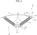
- FIG. 2 is a partial cross-sectional view illustrating the configuration of one magnetic pole portion of the embedded magnet rotor 100 according to the embodiment.
- An area sandwiched by radially inner ends of the two permanent magnet housing spaces 121 forming the V-shape functions as a center bridge 126 that connects portions, in the rotor core 120, located on a radially outer side and a radially inner side of the two permanent magnet housing spaces 121. It should be noted that though there is a center flux barrier 125 in the middle of the center bridge 126 in FIG. 2 , the center flux barrier 125 is not essential.
- the permanent magnet housing spaces 121 each have, in addition to a portion where to house the permanent magnet 130, a partial space that is located on a radially outer side of the permanent magnet 130.
- the permanent magnet housing spaces 121 each have an outer partial space 122 that is a portion located on a more radially outer side than the permanent magnet 130, that is, a portion on a side far from the center bridge 126.
- the outer partial spaces 122 communicate with the gap space 15 through communication openings 128.
- the communication openings 128 are each sandwiched by two chips 127a and 127b forming part of the outer peripheral surface of the rotor core 120.
- a magnet holding outer projection 123b in a projecting shape which is part of the rotor core 120, is formed between the permanent magnet 130 and the outer partial space 122 to resist a centrifugal force applied to the permanent magnet 130 during the rotation of the embedded magnet rotor 100.
- the magnet holding outer projections 123b are each formed on a radial-direction inner surface of the permanent magnet housing space 121.
- the permanent magnet housing spaces 121 each further have an inner partial space 124 that is a portion on a more radially inner side than the permanent magnet 130, that is, a portion close to the center bridge 126.
- FIG. 3 is a partial cross-sectional view illustrating an example of breakage of one of the permanent magnets 130 of the embedded magnet rotor 100 according to the embodiment.
- the centrifugal force applied to the permanent magnet 130 is received by a radial-direction outer wall 121a of the permanent magnet housing space 121 and the magnet holding outer projection 123b.
- an interval between a tip of the magnet holding outer projection 123b and the radial-direction outer wall 121a is represented by the symbol "H".
- a radially outer end surface 130b of the permanent magnet 130 is in contact with the magnet holding outer projection 123b at its portion close to a radial-direction inner side surface 130c of the permanent magnet 130, and nothing is in contact with its other portion, that is, its portion corresponding to the length H.
- the tip of the magnet holding outer projection 123b is in contact with a tip contact portion 123p of the radially outer end surface 130b of the permanent magnet 130. Then, stress concentration occurs at the tip contact portion 123p.
- the tip contact portion 123p is highly likely to be a starting point of the occurrence of a defect of the permanent magnet 130. Further, in the radially outer end surface 130b of the permanent magnet 130, the portion held by the magnet holding outer projection 123b suffers a compressive stress but another portion not held by the magnet holding outer projection 123b is given a radially outward load due to the centrifugal force. As a result, in the defect starting from the tip contact portion 123p, a tensile stress component in a direction along the radially outer end surface 130b of the permanent magnet 130 is generated. This tensile stress component will be a cause making the defect starting from the tip contact portion 123p develop as a crack 131 toward the inside of the permanent magnet 130.
- the crack 131 propagates toward the radially inner side of a radially outer corner portion 132c of the permanent magnet 130.
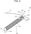
- FIG. 4 is a partial cross-sectional view illustrating the state of a fragment 132 in the case of the example of the breakage of the one permanent magnet 130 of the embedded magnet rotor 100 according to the embodiment.
- the fragment 132 is supposed to move while the radially outer corner portion 132c is on the radially outer side, because of the direction of the centrifugal force applied to the fragment 132.
- this is supposed to be a state in which the portion of the radially outer end surface 130b and the portion of the radial-direction outer side surface 130a are constrained respectively by the chip 127a and the chip 127b and the radially outer corner portion 132c is present in the communication opening 128.
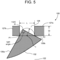
- FIG. 5 is an enlarged view of the vicinity of the communication opening 128 in FIG. 4 illustrating the state of the fragment 132 in the case of the example of the breakage of the one permanent magnet 130 of the embedded magnet rotor 100 according to the embodiment.
- the fragment 132 is protruding into the communication opening 128 from the inside of the outer partial space 122.
- the radial-direction outer side surface 130a of the fragment 132 is in contact with an inner corner portion of the chip 127b at P1 and the radially outer end surface 130b of the fragment 132 is in contact with an inner corner portion of the chip 127a at P2.
- point Pt being the radially outer corner portion 132c of the fragment 132, point P1, and point P2 form a right triangle. Therefore, the trajectory of point Pt is a semicircle whose diameter is an interval between point P1 and point P2, that is, the width L of the communication opening 128, as illustrated in FIG. 5 .
- the radius r is 1/2 of the diameter L.
- the width L of the communication opening 128 needs to have a dimension more than or equal to twice the thickness T of the electromagnet steel sheet 120a, considering manufacturing constrains.
- the embedded magnet rotor 100 satisfies the conditions of the following expression (1) and expression (2) regarding the outer partial space 122 of the permanent magnet housing space 121.
- 2 ⁇ T ⁇ L ⁇ H L / 2 ⁇ W ⁇ ⁇
- H stands for the interval, illustrated in FIG. 3 , between the tip of the magnet holding outer projection 123b and the radial-direction outer wall 121a
- L stands for the width of the communication opening
- W stands for the radial thickness of each of the two chips
- T stands for the sheet thickness of each of the electromagnetic steel sheets 120a
- ⁇ stands for the radial width of the gap space 15.
- the angle of the radially outer corner portion 132c of the fragment 132 in the plan view of FIG. 5 is larger than 90 degrees, and thus the aforesaid expressin (1) is satisfied with a larger margin.
- the embedded magnet rotor 100 is configured to prevent the fragment 132 of the permanent magnet 130 from protruding into the gap space 15.
- the embedded magnet rotor and the rotary electric machine in which the fragment of the permanent magnet does not protrude into the gap space even if the permanent magnet breaks.
- stator stator
- 11 stator tooth
- 15 gap space
- 100 embedded magnet rotor
- 110 rotor shaft
- 120 rotor core
- 120a electromagnetic steel sheet
- 121 permanent magnet housing space
- 121a radial-direction outer wall
- 122 outer partial space
- 123a magnet holding inner projection
- 123b magnet holding outer projection
- 123p tip contact portion
- 124 inner partial space
- 125 center flux barrier
- 126 center bridge
- 127a, 127b chip
- 128 communication opening
- 130 permanent magnet
- 130a radial-direction outer side surface
- 130b radially outer end surface
- 130c radial-direction inner side surface
- 132c radially outer corner portion
- 200 rotary electric machine
Landscapes
- Engineering & Computer Science (AREA)
- Power Engineering (AREA)
- Permanent Field Magnets Of Synchronous Machinery (AREA)
Abstract
Description
- The present invention relates to an embedded magnet rotor and a rotary electric machine including the same.
- In a rotary electric machine including an embedded magnet rotor, permanent magnets are housed in through holes formed in regions near a radially outer side in a rotor core and extending in the axial direction. Typically, the through holes each have not only a space where to house the permanent magnet but also a partial space on its radially outer side. The partial space on the radially outer side is a flux barrier for hindering the passage of a magnetic flux.
- In many cases, top bridges which are part of the rotor core are present between the partial spaces on the radially outer side and the outer surface of the rotor core to strengthen the structure of the rotor core.
- The top bridges serve as paths of the fluxes, that is, magnetic paths. The fluxes that pass through the magnetic paths become leakage fluxes that stay only inside the rotor side and are not linked with the stator side, leading to low torque efficiency of the rotary electric machine.
- With this as a background, some rotors used are of a type having no top bridges and having the aforesaid partial spaces on the radially outer side communicate with a space outside the rotor core (a gap space between the rotor and the stator).
- Patent Document 1:
Japanese Patent No. 5447418 - Though achieving a reduction in leakage fluxes as described above, the embedded magnet rotor with no top bridges requires some measure being taken in case the magnet breaks when an abnormality occurs such as when the rotation speed abnormally increases. Specifically, when any one of the magnets is fragmented, the fragment may protrude into the gap space outside the rotor core through the partial space on the radially outer side.
- The protrusion of the fragment of the magnet into the gap space, if any, causes a problem that the fragment is caught between the rotor and the stator to lock the rotor, which may break the outer surface of the rotor or the inner surface of the stator.
- An object of the present invention is to provide an embedded magnet rotor and a rotary electric machine in which a fragment of a permanent magnet does not protrude into a gap space even if the permanent magnet is broken.
- According to the present invention, there is provided an embedded magnet rotor comprising: a rotor shaft extending in a rotation axis direction; a rotor core disposed on a radially outer side of the rotor shaft, the rotor core having a plurality of permanent magnet housing spaces formed at near radially outer part of the rotor core with circumferential intervals; and flat plate-shaped permanent magnets respectively housed in the plurality of permanent magnet housing spaces, wherein the permanent magnet housing spaces each extend more radially outward than a range where the permanent magnet is held by a magnet holding outer projection formed in the rotor core and each have a communication opening communicating with a gap space between the embedded magnet rotor and a stator arranged on a radially outer side of the embedded magnet rotor, wherein the communication opening is sandwiched by two chips being part of the rotor core and extending in a circumferential direction, and wherein in a cross section perpendicular to the rotation axis direction, a radial thickness of each of the two chips and a circumferential width of the communication opening are in such a dimensional relation as to prevent a fragment produced when the permanent magnet breaks from protruding from the communication opening and coming into contact with the stator.
- According to the present invention, there is provided a rotary electric machine comprising: the embedded magnet rotor; and a stator disposed on a radially outer side of the rotor core.
-
-
FIG. 1 is a cross-sectional view illustrating the structure of a rotary electric machine according to an embodiment. -
FIG. 2 is a partial cross-sectional view illustrating the configuration of one magnetic pole portion of an embedded magnet rotor of the embodiment. -
FIG. 3 is a partial cross-sectional view illustrating an example of breakage of one permanent magnet of the embedded magnet rotor according to the embodiment. -
FIG. 4 is a partial cross-sectional view illustrating the state of a fragment in the case of the example of the breakage of the one permanent magnet of the embedded magnet rotor according to the embodiment. -
FIG. 5 is an enlarged view of the vicinity of a communication opening inFIG. 4 illustrating the state of the fragment in the case of the example of the breakage of the one permanent magnet of the embedded magnet rotor according to the embodiment. - Hereinafter, with reference to the accompanying drawings, embodiments of an embedded magnet rotor and a rotary electric machine of the present invention will be described. The same or similar portions are represented by the same reference symbols, and a duplicate description will be omitted.
-
FIG. 1 is a cross-sectional view illustrating the structure of a rotaryelectric machine 200 according to an embodiment. - The rotary
electric machine 200 includes: an embeddedmagnet rotor 100 having arotor shaft 110 extending in the rotation axis direction, arotor core 120 attached to therotor shaft 110, and a plurality ofpermanent magnets 130; acylindrical stator 10 disposed on a radially outer side of therotor core 120 to surround therotor core 120 across agap space 15; and two bearings (not illustrated) to rotatably support therotor shaft 110. - The
rotor core 120 has a plurality ofelectromagnetic steel sheets 120a laminated in the rotation axis direction. Theelectromagnetic steel sheets 120a each have a punched portion where therotor shaft 110 is to penetrate and punched portions where thepermanent magnets 130 are to penetrate. In the state in which theelectromagnetic steel sheets 120a are laminated, these punched portions form, in therotor core 120, through holes extending in the rotation axis direction. It should be noted that thoughFIG. 1 illustrates, as an example, the case where therotor core 120 has theelectromagnetic steel sheets 120a, this is not restrictive and is also applicable to a solid rotor in which a rotor shaft and a rotor core are integrated. - The
permanent magnets 130 are flat plate-shaped. At each magnetic pole, two permanentmagnet housing spaces 121 for housing the respective twopermanent magnets 130 are arranged in a V-shape projecting radially inward. It should be noted that thoughFIG. 1 illustrates, as an example, the case where thepermanent magnets 130 are arranged in the V-shape, this is not restrictive and such arrangement without the V-shape is applicable to a case where the arrangement has a problem of the protrusion of a fragment. - On the inner periphery of the
stator 10, a plurality ofstator teeth 11 for a stator winding (not illustrated) are formed at intervals in the circumferential direction. - Here, the radial width of the
gap space 15 is represented by the symbol "δ". - Specifically, the radial width δ of the
gap space 15 is an interval between the outer peripheral surface of therotor core 120 and an inner circumferential envelope surface of thestator 10, that is, a radially inner top of thestator tooth 11. -
FIG. 2 is a partial cross-sectional view illustrating the configuration of one magnetic pole portion of the embeddedmagnet rotor 100 according to the embodiment. - An area sandwiched by radially inner ends of the two permanent
magnet housing spaces 121 forming the V-shape functions as acenter bridge 126 that connects portions, in therotor core 120, located on a radially outer side and a radially inner side of the two permanentmagnet housing spaces 121. It should be noted that though there is acenter flux barrier 125 in the middle of thecenter bridge 126 inFIG. 2 , thecenter flux barrier 125 is not essential. - The permanent
magnet housing spaces 121 each have, in addition to a portion where to house thepermanent magnet 130, a partial space that is located on a radially outer side of thepermanent magnet 130. - Specifically, the permanent
magnet housing spaces 121 each have an outerpartial space 122 that is a portion located on a more radially outer side than thepermanent magnet 130, that is, a portion on a side far from thecenter bridge 126. The outerpartial spaces 122 communicate with thegap space 15 throughcommunication openings 128. - The
communication openings 128 are each sandwiched by twochips rotor core 120. - In each of the permanent
magnet housing spaces 121, a magnet holdingouter projection 123b in a projecting shape, which is part of therotor core 120, is formed between thepermanent magnet 130 and the outerpartial space 122 to resist a centrifugal force applied to thepermanent magnet 130 during the rotation of the embeddedmagnet rotor 100. The magnet holdingouter projections 123b are each formed on a radial-direction inner surface of the permanentmagnet housing space 121. - The permanent
magnet housing spaces 121 each further have an innerpartial space 124 that is a portion on a more radially inner side than thepermanent magnet 130, that is, a portion close to thecenter bridge 126. -
FIG. 3 is a partial cross-sectional view illustrating an example of breakage of one of thepermanent magnets 130 of the embeddedmagnet rotor 100 according to the embodiment. - While the embedded
magnet rotor 100 is rotating, the centrifugal force applied to thepermanent magnet 130 is received by a radial-directionouter wall 121a of the permanentmagnet housing space 121 and the magnet holdingouter projection 123b. - There is no projection on the radial-direction
outer wall 121a with which a radial-directionouter side surface 130a of thepermanent magnet 130 is in contact. - As indicated in
FIG. 3 , an interval between a tip of the magnet holdingouter projection 123b and the radial-directionouter wall 121a is represented by the symbol "H". - A radially
outer end surface 130b of thepermanent magnet 130 is in contact with the magnet holdingouter projection 123b at its portion close to a radial-directioninner side surface 130c of thepermanent magnet 130, and nothing is in contact with its other portion, that is, its portion corresponding to the length H. The tip of the magnet holdingouter projection 123b is in contact with atip contact portion 123p of the radiallyouter end surface 130b of thepermanent magnet 130. Then, stress concentration occurs at thetip contact portion 123p. - Therefore, the
tip contact portion 123p is highly likely to be a starting point of the occurrence of a defect of thepermanent magnet 130. Further, in the radiallyouter end surface 130b of thepermanent magnet 130, the portion held by the magnet holdingouter projection 123b suffers a compressive stress but another portion not held by the magnet holdingouter projection 123b is given a radially outward load due to the centrifugal force. As a result, in the defect starting from thetip contact portion 123p, a tensile stress component in a direction along the radiallyouter end surface 130b of thepermanent magnet 130 is generated. This tensile stress component will be a cause making the defect starting from thetip contact portion 123p develop as acrack 131 toward the inside of thepermanent magnet 130. - Because of the above, the
crack 131 propagates toward the radially inner side of a radiallyouter corner portion 132c of thepermanent magnet 130. -
FIG. 4 is a partial cross-sectional view illustrating the state of afragment 132 in the case of the example of the breakage of the onepermanent magnet 130 of the embeddedmagnet rotor 100 according to the embodiment. - The penetration of the
crack 131 illustrated inFIG. 3 through thepermanent magnet 130 results in the production of thefragment 132. Since thecrack 131 develops toward the radially inner side of the radiallyouter corner portion 132c of thepermanent magnet 130 as described above, the radiallyouter corner portion 132c remains in thefragment 132. - Further, in the embedded
magnet rotor 100, thefragment 132 is supposed to move while the radiallyouter corner portion 132c is on the radially outer side, because of the direction of the centrifugal force applied to thefragment 132. - That is, this is supposed to be a state in which the portion of the radially
outer end surface 130b and the portion of the radial-directionouter side surface 130a are constrained respectively by thechip 127a and thechip 127b and the radiallyouter corner portion 132c is present in thecommunication opening 128. -
FIG. 5 is an enlarged view of the vicinity of thecommunication opening 128 inFIG. 4 illustrating the state of thefragment 132 in the case of the example of the breakage of the onepermanent magnet 130 of the embeddedmagnet rotor 100 according to the embodiment. - The
fragment 132 is protruding into thecommunication opening 128 from the inside of the outerpartial space 122. - In this state, the radial-direction
outer side surface 130a of thefragment 132 is in contact with an inner corner portion of thechip 127b at P1 and the radiallyouter end surface 130b of thefragment 132 is in contact with an inner corner portion of thechip 127a at P2. - In the cross section in
FIG. 5 perpendicular to the extension direction of the rotation axis of therotor shaft 110, point Pt being the radiallyouter corner portion 132c of thefragment 132, point P1, and point P2 form a right triangle. Therefore, the trajectory of point Pt is a semicircle whose diameter is an interval between point P1 and point P2, that is, the width L of thecommunication opening 128, as illustrated inFIG. 5 . Here, the radius r is 1/2 of the diameter L. - The width L of the
communication opening 128 needs to have a dimension more than or equal to twice the thickness T of theelectromagnet steel sheet 120a, considering manufacturing constrains. - It follows that in the case where the radius r is smaller than the thickness W of the
chip 127a and thechip 127b, the radial-directionouter side surface 130a of thefragment 132 does not protrude from the outer peripheral surface of the embeddedmagnet rotor 100. - Based on the above, the embedded
magnet rotor 100 according to the embodiment satisfies the conditions of the following expression (1) and expression (2) regarding the outerpartial space 122 of the permanentmagnet housing space 121.

- Here, "H" stands for the interval, illustrated in
FIG. 3 , between the tip of the magnet holdingouter projection 123b and the radial-directionouter wall 121a, "L" stands for the width of the communication opening, "W" stands for the radial thickness of each of the two chips, "T" stands for the sheet thickness of each of theelectromagnetic steel sheets 120a, and "δ" stands for the radial width of thegap space 15. Note that "X = < Y" indicates that X is equal to or less than Y. - In the case where the
fragment 132 is inclined with respect to the rotation axis direction, inFIG. 5 , the angle of the radiallyouter corner portion 132c of thefragment 132 in the plan view ofFIG. 5 is larger than 90 degrees, and thus the aforesaid expressin (1) is satisfied with a larger margin. - Therefore, satisfying the conditions of expression (1) and expression (2), the embedded
magnet rotor 100 according to this embodiment is configured to prevent thefragment 132 of thepermanent magnet 130 from protruding into thegap space 15. - As described above, according to the present embodiment, it is possible to provide the embedded magnet rotor and the rotary electric machine in which the fragment of the permanent magnet does not protrude into the gap space even if the permanent magnet breaks.
- While embodiment of the present invention has been described, the embodiment has been presented by way of example only, and is not intended to limit the scope of the invention. Features of the embodiment may be used in combination. Furthermore, the embodiment may be embodied in other various forms. Various omissions, replacements and changes may be made without departing from the spirit of the invention. The embodiment and variants thereof are within the scope and spirit of the invention, and are similarly within the scope of the invention defined in the appended claims and the range of equivalency thereof.
- 10: stator, 11: stator tooth, 15: gap space, 100: embedded magnet rotor, 110: rotor shaft, 120: rotor core, 120a: electromagnetic steel sheet, 121: permanent magnet housing space, 121a: radial-direction outer wall, 122: outer partial space, 123a: magnet holding inner projection, 123b: magnet holding outer projection, 123p: tip contact portion, 124: inner partial space, 125: center flux barrier, 126: center bridge, 127a, 127b: chip, 128: communication opening, 130: permanent magnet, 130a: radial-direction outer side surface, 130b: radially outer end surface, 130c: radial-direction inner side surface, 132c: radially outer corner portion, 200: rotary electric machine
Claims (4)
- An embedded magnet rotor comprising:a rotor shaft extending in a rotation axis direction;a rotor core disposed on a radially outer side of the rotor shaft, the rotor core having a plurality of permanent magnet housing spaces formed at near radially outer part of the rotor core with circumferential intervals; andflat plate-shaped permanent magnets respectively housed in the plurality of permanent magnet housing spaces,wherein the permanent magnet housing spaces each extend more radially outward than a range where the permanent magnet is held by a magnet holding outer projection formed in the rotor core and each have a communication opening communicating with a gap space between the embedded magnet rotor and a stator arranged on a radially outer side of the embedded magnet rotor,wherein the communication opening is sandwiched by two chips being part of the rotor core and extending in a circumferential direction, andwherein in a cross section perpendicular to the rotation axis direction, a radial thickness of each of the two chips and a circumferential width of the communication opening are in such a dimensional relation as to prevent a fragment produced when the permanent magnet breaks from protruding from the communication opening and coming into contact with the stator.
- The embedded magnet rotor according to claim 1,wherein the rotor core has a plurality of laminated electromagnetic steel sheets, andwherein the dimensional relation satisfies the following expression (1) and expression (2),


- The embedded magnet rotor according to claim 1 or 2, wherein the plurality of permanent magnet housing spaces are arranged in pairs, and at each pole portion, each of the pairs is arranged in a V-shape projecting radially inward.
- A rotary electric machine comprising:the embedded magnet rotor according to any one of claims 1 to claim 3; anda stator disposed on a radially outer side of the rotor core.
Applications Claiming Priority (1)
| Application Number | Priority Date | Filing Date | Title |
|---|---|---|---|
| PCT/JP2022/015396 WO2023187971A1 (en) | 2022-03-29 | 2022-03-29 | Embedded magnet rotor and rotating electrical machine |
Publications (2)
| Publication Number | Publication Date |
|---|---|
| EP4503390A1 true EP4503390A1 (en) | 2025-02-05 |
| EP4503390A4 EP4503390A4 (en) | 2025-11-05 |
Family
ID=83558421
Family Applications (1)
| Application Number | Title | Priority Date | Filing Date |
|---|---|---|---|
| EP22809630.1A Pending EP4503390A4 (en) | 2022-03-29 | 2022-03-29 | ROTOR WITH EMBEDDED MAGNET AND ELECTRIC LATHE |
Country Status (5)
| Country | Link |
|---|---|
| US (1) | US12218548B2 (en) |
| EP (1) | EP4503390A4 (en) |
| JP (1) | JP7151023B1 (en) |
| CN (1) | CN117157853A (en) |
| WO (1) | WO2023187971A1 (en) |
Families Citing this family (1)
| Publication number | Priority date | Publication date | Assignee | Title |
|---|---|---|---|---|
| JP7799761B1 (en) * | 2024-07-16 | 2026-01-15 | 株式会社東芝 | Permanent magnet rotor and rotating electric machine |
Family Cites Families (16)
| Publication number | Priority date | Publication date | Assignee | Title |
|---|---|---|---|---|
| US4327302A (en) * | 1979-09-21 | 1982-04-27 | General Electric Company | Electronically commutated motor, stationary and rotatable assemblies therefore, and lamination |
| DE10153750A1 (en) * | 2001-10-31 | 2003-05-22 | Siemens Ag | Rotor for PM synchronous machine |
| JP2005130604A (en) * | 2003-10-23 | 2005-05-19 | Nissan Motor Co Ltd | Magnetic steel sheet forming body, rotor for a built-in permanent magnet rotating machine using the same, rotating machine with built-in permanent magnet, and vehicle using this built-in permanent magnet rotating machine |
| US7385328B2 (en) * | 2006-05-23 | 2008-06-10 | Reliance Electric Technologies, Llc | Cogging reduction in permanent magnet machines |
| JP5447418B2 (en) | 2011-03-28 | 2014-03-19 | 株式会社豊田自動織機 | Rotating electric machine permanent magnet embedded rotor and rotating electric machine |
| CN103999330B (en) * | 2011-11-30 | 2017-03-29 | Abb研究有限公司 | Motor and rotor |
| JP5851365B2 (en) * | 2012-08-31 | 2016-02-03 | 日立オートモティブシステムズ株式会社 | Rotating electric machine |
| JP2014064422A (en) * | 2012-09-24 | 2014-04-10 | Daikin Ind Ltd | Rotor core and method manufacturing the same |
| JP5958305B2 (en) * | 2012-11-29 | 2016-07-27 | スズキ株式会社 | IPM type electric rotating machine |
| JP2015202027A (en) * | 2014-03-31 | 2015-11-12 | ダイキン工業株式会社 | Rotor |
| JP2015195638A (en) * | 2014-03-31 | 2015-11-05 | ダイキン工業株式会社 | rotor |
| JP6357859B2 (en) * | 2014-05-12 | 2018-07-18 | 富士電機株式会社 | Permanent magnet embedded rotary electric machine |
| EP3309931B1 (en) * | 2015-06-15 | 2021-07-21 | Mitsubishi Electric Corporation | Permanent magnet-embedded motor and compressor |
| JP2017112705A (en) * | 2015-12-16 | 2017-06-22 | 富士電機株式会社 | Permanent magnet type rotating electrical machine and manufacturing method thereof |
| CN113994569B (en) * | 2019-09-24 | 2024-07-30 | 株式会社东芝 | Rotor of rotating electrical machine |
| WO2022059199A1 (en) * | 2020-09-18 | 2022-03-24 | 株式会社 東芝 | Rotor |
-
2022
- 2022-03-29 EP EP22809630.1A patent/EP4503390A4/en active Pending
- 2022-03-29 CN CN202280003622.2A patent/CN117157853A/en active Pending
- 2022-03-29 JP JP2022543524A patent/JP7151023B1/en active Active
- 2022-03-29 WO PCT/JP2022/015396 patent/WO2023187971A1/en not_active Ceased
- 2022-12-09 US US18/064,033 patent/US12218548B2/en active Active
Also Published As
| Publication number | Publication date |
|---|---|
| EP4503390A4 (en) | 2025-11-05 |
| JP7151023B1 (en) | 2022-10-11 |
| JPWO2023187971A1 (en) | 2023-10-05 |
| US12218548B2 (en) | 2025-02-04 |
| CN117157853A (en) | 2023-12-01 |
| WO2023187971A1 (en) | 2023-10-05 |
| US20230318373A1 (en) | 2023-10-05 |
Similar Documents
| Publication | Publication Date | Title |
|---|---|---|
| US8957561B2 (en) | Rotor for rotary electric machine | |
| JP5045373B2 (en) | Permanent magnet motor rotor | |
| EP3273573A1 (en) | Rotor for rotating electrical machine | |
| US12283848B2 (en) | Rotor for rotary electric machine | |
| US12301059B2 (en) | Rotating electric machine | |
| CN110140279A (en) | Rotor for dynamo-electric machine | |
| US9570947B2 (en) | Electric rotating machine | |
| JP2007068357A (en) | Rotating electric machine rotor and rotating electric machine using the same | |
| US12218548B2 (en) | Embedded magnet rotor and rotary electric machine | |
| CN107769412A (en) | Rotor pack and associated rotor and the electro-motor comprising the rotor pack | |
| JP6357859B2 (en) | Permanent magnet embedded rotary electric machine | |
| EP3866305A1 (en) | Rotor, and rotary electric machine provided with same | |
| JP5623147B2 (en) | Abduction type rotating electrical machine | |
| CN109983676A (en) | Synchronous reluctance type rotating electric machine | |
| JP5264551B2 (en) | Electric motor, blower and compressor | |
| CN102377307B (en) | Rotating electric machine and manufacturing method thereof | |
| US11139705B2 (en) | Electric motor | |
| JP5879848B2 (en) | Rotor for interior magnet type rotary electric machine | |
| EP4443705A1 (en) | Rotating electric machine | |
| JP4042623B2 (en) | Split core type stator | |
| JP2016226218A (en) | Permanent magnet embedded rotor for rotary electric machine | |
| CN114915064B (en) | Rotor and brushless motor | |
| JP4376586B2 (en) | Electric motor | |
| CN112436630B (en) | Rotor with embedded magnet | |
| CN114915065B (en) | Rotor and brushless motor |
Legal Events
| Date | Code | Title | Description |
|---|---|---|---|
| STAA | Information on the status of an ep patent application or granted ep patent |
Free format text: STATUS: UNKNOWN |
|
| STAA | Information on the status of an ep patent application or granted ep patent |
Free format text: STATUS: THE INTERNATIONAL PUBLICATION HAS BEEN MADE |
|
| PUAI | Public reference made under article 153(3) epc to a published international application that has entered the european phase |
Free format text: ORIGINAL CODE: 0009012 |
|
| STAA | Information on the status of an ep patent application or granted ep patent |
Free format text: STATUS: REQUEST FOR EXAMINATION WAS MADE |
|
| 17P | Request for examination filed |
Effective date: 20221202 |
|
| AK | Designated contracting states |
Kind code of ref document: A1 Designated state(s): AL AT BE BG CH CY CZ DE DK EE ES FI FR GB GR HR HU IE IS IT LI LT LU LV MC MK MT NL NO PL PT RO RS SE SI SK SM TR |
|
| DAV | Request for validation of the european patent (deleted) | ||
| DAX | Request for extension of the european patent (deleted) | ||
| RAP1 | Party data changed (applicant data changed or rights of an application transferred) |
Owner name: KABUSHIKI KAISHA TOSHIBA |
|
| A4 | Supplementary search report drawn up and despatched |
Effective date: 20251007 |
|
| RIC1 | Information provided on ipc code assigned before grant |
Ipc: H02K 1/276 20220101AFI20250930BHEP |