EP4503355A1 - Gas-insulated switchgear - Google Patents
Gas-insulated switchgear Download PDFInfo
- Publication number
- EP4503355A1 EP4503355A1 EP22935487.3A EP22935487A EP4503355A1 EP 4503355 A1 EP4503355 A1 EP 4503355A1 EP 22935487 A EP22935487 A EP 22935487A EP 4503355 A1 EP4503355 A1 EP 4503355A1
- Authority
- EP
- European Patent Office
- Prior art keywords
- switch
- manipulator
- general switch
- manipulators
- general
- Prior art date
- Legal status (The legal status is an assumption and is not a legal conclusion. Google has not performed a legal analysis and makes no representation as to the accuracy of the status listed.)
- Granted
Links
Images


Classifications
-
- H—ELECTRICITY
- H02—GENERATION; CONVERSION OR DISTRIBUTION OF ELECTRIC POWER
- H02B—BOARDS, SUBSTATIONS OR SWITCHING ARRANGEMENTS FOR THE SUPPLY OR DISTRIBUTION OF ELECTRIC POWER
- H02B13/00—Arrangement of switchgear in which switches are enclosed in, or structurally associated with, a casing, e.g. cubicle
- H02B13/02—Arrangement of switchgear in which switches are enclosed in, or structurally associated with, a casing, e.g. cubicle with metal casing
- H02B13/035—Gas-insulated switchgear
-
- H—ELECTRICITY
- H01—ELECTRIC ELEMENTS
- H01H—ELECTRIC SWITCHES; RELAYS; SELECTORS; EMERGENCY PROTECTIVE DEVICES
- H01H33/00—High-tension or heavy-current switches with arc-extinguishing or arc-preventing means
- H01H33/02—Details
- H01H33/53—Cases; Reservoirs, tanks, piping or valves, for arc-extinguishing fluid; Accessories therefor, e.g. safety arrangements, pressure relief devices
- H01H33/56—Gas reservoirs
-
- H—ELECTRICITY
- H01—ELECTRIC ELEMENTS
- H01H—ELECTRIC SWITCHES; RELAYS; SELECTORS; EMERGENCY PROTECTIVE DEVICES
- H01H3/00—Mechanisms for operating contacts
- H01H3/32—Driving mechanisms, i.e. for transmitting driving force to the contacts
- H01H3/36—Driving mechanisms, i.e. for transmitting driving force to the contacts using belt, chain, or cord
-
- H—ELECTRICITY
- H01—ELECTRIC ELEMENTS
- H01H—ELECTRIC SWITCHES; RELAYS; SELECTORS; EMERGENCY PROTECTIVE DEVICES
- H01H33/00—High-tension or heavy-current switches with arc-extinguishing or arc-preventing means
- H01H33/02—Details
- H01H33/28—Power arrangements internal to the switch for operating the driving mechanism
- H01H33/285—Power arrangements internal to the switch for operating the driving mechanism using electro-dynamic repulsion
-
- H—ELECTRICITY
- H01—ELECTRIC ELEMENTS
- H01H—ELECTRIC SWITCHES; RELAYS; SELECTORS; EMERGENCY PROTECTIVE DEVICES
- H01H33/00—High-tension or heavy-current switches with arc-extinguishing or arc-preventing means
- H01H33/02—Details
- H01H33/28—Power arrangements internal to the switch for operating the driving mechanism
- H01H33/36—Power arrangements internal to the switch for operating the driving mechanism using dynamo-electric motor
-
- H—ELECTRICITY
- H01—ELECTRIC ELEMENTS
- H01H—ELECTRIC SWITCHES; RELAYS; SELECTORS; EMERGENCY PROTECTIVE DEVICES
- H01H33/00—High-tension or heavy-current switches with arc-extinguishing or arc-preventing means
- H01H33/02—Details
- H01H33/42—Driving mechanisms
-
- H—ELECTRICITY
- H01—ELECTRIC ELEMENTS
- H01H—ELECTRIC SWITCHES; RELAYS; SELECTORS; EMERGENCY PROTECTIVE DEVICES
- H01H31/00—Air-break switches for high tension without arc-extinguishing or arc-preventing means
- H01H31/003—Earthing switches
-
- H—ELECTRICITY
- H02—GENERATION; CONVERSION OR DISTRIBUTION OF ELECTRIC POWER
- H02B—BOARDS, SUBSTATIONS OR SWITCHING ARRANGEMENTS FOR THE SUPPLY OR DISTRIBUTION OF ELECTRIC POWER
- H02B13/00—Arrangement of switchgear in which switches are enclosed in, or structurally associated with, a casing, e.g. cubicle
- H02B13/02—Arrangement of switchgear in which switches are enclosed in, or structurally associated with, a casing, e.g. cubicle with metal casing
- H02B13/035—Gas-insulated switchgear
- H02B13/075—Earthing arrangements
Definitions
- the present disclosure relates to a gas-insulated switch including a general switch.
- a gas-insulated switch in which general switches including a disconnector and a grounding switch, in addition to a breaker, are housed in a tank enclosing insulating gas uses a method for: installing a general switch manipulator that is a power source of a switching operation of each general switch outside the tank; and transmitting rotational force from each general switch manipulator to each general switch with a wire so as to cause the general switch to perform the switching operation.
- the general switch manipulator Since the general switch manipulator is installed separately from a breaker manipulator that is a power source of a switching operation of the breaker, an attachment position of the general switch manipulator has been changed according to an arrangement layout of the general switch. However, when the attachment position of the general switch manipulator changes, it is necessary to change a device fixing method. Therefore, there has been a problem in that the number of models increases and it is necessary to individually design each model.
- a gas-insulated switch disclosed in Patent Literature 1 houses a plurality of manipulators in a box disposed on a rack.
- the gas-insulated switch disclosed in Patent Literature 1 since the plurality of manipulators is housed in the box, it is not necessary to change the attachment position of the general switch manipulator according to the arrangement layout of the general switch.
- Patent Literature 1 International Publication Pamphlet No. 2015/111133
- Patent Literature 1 does not disclose a method for avoiding wire bending, when the plurality of general switch manipulators are housed in a box, it is necessary to widen an interval between the general switch manipulators. In this way, Patent Literature 1 does not disclose a method for reducing an installation space of the general switch manipulator.
- the present disclosure has been made in view of the above, and an object of the present disclosure is to obtain a gas-insulated switch that does not need to change an attachment position of a general switch manipulator according to an arrangement layout of the general switch and reduces a space where the general switch manipulator is installed.
- a gas-insulated switch includes: a conductor configured to form a power transmission circuit; a breaker configured to cut off a current flowing in the conductor; a plurality of general switches including a disconnector that separates a part of the conductor, a grounding switch that grounds the conductor separated from the power transmission circuit by the disconnector, and a switching operation unit that opens and closes with rotation of a driven pulley; the breaker manipulator that causes the breaker to perform a switching operation; a plurality of the general switch manipulators that include a motor and a driving pulley rotationally driven by the motor; a wire that transmits rotational force of the driving pulley to the driven pulley; and a housing that houses the breaker manipulator and the general switch manipulator.
- two general switch manipulators are arranged in the horizontal direction and set as a set, and each set is disposed above the breaker manipulator, in the housing.
- the wire is put around the driving pulley, from a direction different from a direction in which another general switch manipulator in the same set is disposed.
- an effect is achieved that a gas-insulated switch is obtained that does not need to change an attachment position of a general switch manipulator according to an arrangement layout of the general switch and reduces a space where the general switch manipulator is installed.
- FIG. 1 is a system configuration diagram of a gas-insulated switch according to a first embodiment.
- a gas-insulated switch 100 according to the first embodiment includes a tank 10 enclosing insulating gas. Inside of the tank 10 includes; a conductor 11 that forms a power transmission circuit; a breaker 12 configured to cut off a current flowing in the conductor 11; a disconnector 13 configured to disconnect a part of the conductor 11; and a grounding switch 14 configured to ground the conductor 11 separated from the power transmission circuit by the disconnector 13.
- the gas-insulated switch 100 includes: a breaker manipulator 20 that is a power source of a switching operation of the breaker 12; and a plurality of general switch manipulators 30 that are power sources of a switching operating of each general switch 50 including the disconnector 13 and the grounding switch 14.
- the gas-insulated switch 100 according to the first embodiment includes the two disconnectors 13 and the two grounding switches 14. That is, the gas-insulated switch 100 according to the first embodiment includes the four general switches 50.
- the general switch manipulator 30 includes a motor 31 and a driving pulley 32 rotationally driven by the motor 31.
- Each general switch 50 includes: a driven pulley 51 configured to receive driving force of the switching operation from the general switch manipulator 30; a movable junction 52 that moves with rotation of the driven pulley 51; and a fixed junction 53 that is fixed to the conductor 11.
- the general switch 50 may include a Geneva mechanism that converts a continuous rotational motion of the driven pulley 51 into an intermittent rotational motion of the movable junction 52.
- the general switch 50 is configured to perform a switching operation by switching a closed state where the movable junction 52 has contact with the fixed junction 53 and an opened state where the movable junction 52 does not have contact with the fixed junction 53.
- a wire 60 that is a rotational force transmitting member is stretched between the driving pulley 32 and the driven pulley 51.
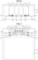
- FIG. 2 is a horizontal cross-sectional view of a housing that houses the general switch manipulator and the breaker manipulator of the gas-insulated switch according to the first embodiment.
- FIG. 3 is a vertical cross-sectional view of the housing that houses the general switch manipulator and the breaker manipulator of the gas-insulated switch according to the first embodiment.
- FIG. 2 illustrates a horizontal cross section of a housing 70 taken along a II-II line in FIG. 1 .
- FIG. 3 illustrates a vertical cross section of the housing 70 taken along a III-III line in FIG. 1 .
- Each general switch manipulator 30 is housed in the housing 70 common to the breaker manipulator 20.
- the two general switch manipulators 30 arranged in the horizontal direction and set as a set, and each set is disposed above the breaker manipulator 20.
- the two sets of the general switch manipulators 30 are arranged in the vertical direction and housed.
- the wire 60 is put around the driving pulley 32, from a direction opposite to a direction in which another general switch manipulator 30 in the same set is disposed.
- the wire 60 is drawn out from the housing 70 through a wire hole 71 formed in the housing 70.
- the breaker manipulator 20 and the general switch manipulator 30 are housed in the common housing 70, there is no need to change an attachment position of the general switch manipulator 30 according to an installation layout of the general switch 50. Furthermore, since the breaker manipulator 20 and the general switch manipulator 30 are housed in the common housing 70, maintenance of the breaker manipulator 20 and the general switch manipulator 30 is easy. Furthermore, it is necessary to open/close the plurality of general switches 50 in a determined order. However, since the plurality of the general switch manipulators 30 is collectively installed in the housing 70 in the gas-insulated switch 100 according to the first embodiment, an operation for switching the general switches 50 in the determined order can be easily and manually performed.
- FIG. 4 is a horizontal cross-sectional view of the housing that houses the general switch manipulator and the breaker manipulator of the gas-insulated switch according to a second embodiment.
- FIG. 5 is a vertical cross-sectional view of the housing that houses the general switch manipulator and the breaker manipulator of the gas-insulated switch according to the second embodiment.
- the plurality of the general switch manipulators 30 are housed in the housing 70 common to the breaker manipulator 20.
- the two general switch manipulators 30 are arranged in the horizontal direction and set as a set, and each set is disposed above the breaker manipulator 20.
- the two sets of the general switch manipulators 30 are arranged in the horizontal direction and housed.
- the wire 60 is put around the driving pulley 32, from a direction opposite to a direction in which another general switch manipulator 30 in the same set is disposed.
- the wire 60 is drawn out from the housing 70 through the wire hole 71 formed in the housing 70.
- the wires 60 put around the driving pulleys 32 of the respective two adjacent the general switch manipulators 30 included in different sets are shifted to the upside and the downside and are drawn in the housing 70.
- the maintenance of the breaker manipulator 20 and the general switch manipulator 30 is easy, and the operation for switching the general switches 50 in the determined order can be easily and manually performed.
- each general switch manipulator 30 is installed at the same height.
- the set of the general switch manipulators 30 are arranged in the vertical direction, it is necessary to install a stepstool for enabling to manually operate the set of upper and lower for the general switch manipulators 30.
- the plurality of the general switch manipulators 30 are installed at the same height, it is possible to manually operate all the general switch manipulators 30 without installing the stepstool. Therefore, as compared with the gas-insulated switch 100 according to the first embodiment, in the gas-insulated switch 100 according to the second embodiment, it is possible to further reduce the space where the general switch manipulator 30 is installed.
- FIG. 6 is a horizontal cross-sectional view of the housing that houses the general switch manipulator and the breaker manipulator of the gas-insulated switch according to a third embodiment.
- FIG. 7 is a vertical cross-sectional view of the housing that houses the general switch manipulator and the breaker manipulator of the gas-insulated switch according to the third embodiment.
- the plurality of the general switch manipulators 30 are housed in the housing 70 common to the breaker manipulator 20.
- the two general switch manipulators 30 are arranged in the horizontal direction and set as a set, and each set is disposed above the breaker manipulator 20.
- the two sets of the general switch manipulators 30 are arranged in the horizontal direction and housed.
- the wire 60 is put around the driving pulley 32, from the direction opposite to the direction in which the other general switch manipulator 30 in the same set is disposed.
- the wire 60 is put around the driving pulley 32 from the vertical direction. Therefore, for each of the two general switch manipulators 30 included in the single set, a direction in which the wire 60 is put around the driving pulley 32 is different by 90°.
- the wire 60 is drawn out from the housing 70 through the wire hole 71 formed in the housing 70.
- the maintenance of the breaker manipulator 20 and the general switch manipulator 30 is easy, and the operation for switching the general switches 50 in the determined order can be easily and manually performed.
- the wire 60 is put around the driving pulley 32 from the vertical direction, in one of the two general switch manipulators 30 included in the single set adjacent to the general switch manipulator 30 in the other set. Therefore, as compared with the gas-insulated switch 100 according to the second embodiment, in the gas-insulated switch 100 according to the third embodiment, it is possible to narrow the interval between the sets of the general switch manipulator 30, and it is possible to further reduce the space where the general switch manipulators 30 are installed.
- the plurality of the general switch manipulators 30 is installed at the same height as in the gas-insulated switch 100 according to the second embodiment, it is possible to manually operate all the general switch manipulators 30 without installing the stepstool.
Landscapes
- Engineering & Computer Science (AREA)
- Power Engineering (AREA)
- Gas-Insulated Switchgears (AREA)
Abstract
Description
- The present disclosure relates to a gas-insulated switch including a general switch.
- A gas-insulated switch in which general switches including a disconnector and a grounding switch, in addition to a breaker, are housed in a tank enclosing insulating gas uses a method for: installing a general switch manipulator that is a power source of a switching operation of each general switch outside the tank; and transmitting rotational force from each general switch manipulator to each general switch with a wire so as to cause the general switch to perform the switching operation.
- Since the general switch manipulator is installed separately from a breaker manipulator that is a power source of a switching operation of the breaker, an attachment position of the general switch manipulator has been changed according to an arrangement layout of the general switch. However, when the attachment position of the general switch manipulator changes, it is necessary to change a device fixing method. Therefore, there has been a problem in that the number of models increases and it is necessary to individually design each model.
- A gas-insulated switch disclosed in Patent Literature 1 houses a plurality of manipulators in a box disposed on a rack. In the gas-insulated switch disclosed in Patent Literature 1, since the plurality of manipulators is housed in the box, it is not necessary to change the attachment position of the general switch manipulator according to the arrangement layout of the general switch.
- Patent Literature 1: International Publication Pamphlet No.
2015/111133 - In a case where a plurality of general switch are arranged to be adjacent to each other, it is necessary to prevent a wire from being bent with a curvature equal to or less than a certain value, in order to prevent bending of the wire. However, Patent Literature 1 does not disclose a method for avoiding wire bending, when the plurality of general switch manipulators are housed in a box, it is necessary to widen an interval between the general switch manipulators. In this way, Patent Literature 1 does not disclose a method for reducing an installation space of the general switch manipulator.
- The present disclosure has been made in view of the above, and an object of the present disclosure is to obtain a gas-insulated switch that does not need to change an attachment position of a general switch manipulator according to an arrangement layout of the general switch and reduces a space where the general switch manipulator is installed.
- In order to solve the above problems and to achieve the object, a gas-insulated switch according to the present disclosure includes: a conductor configured to form a power transmission circuit; a breaker configured to cut off a current flowing in the conductor; a plurality of general switches including a disconnector that separates a part of the conductor, a grounding switch that grounds the conductor separated from the power transmission circuit by the disconnector, and a switching operation unit that opens and closes with rotation of a driven pulley; the breaker manipulator that causes the breaker to perform a switching operation; a plurality of the general switch manipulators that include a motor and a driving pulley rotationally driven by the motor; a wire that transmits rotational force of the driving pulley to the driven pulley; and a housing that houses the breaker manipulator and the general switch manipulator. Regarding the plurality of the general switch manipulators, two general switch manipulators are arranged in the horizontal direction and set as a set, and each set is disposed above the breaker manipulator, in the housing. In each of the two general switch manipulators included in the single set, the wire is put around the driving pulley, from a direction different from a direction in which another general switch manipulator in the same set is disposed.
- According to the present disclosure, an effect is achieved that a gas-insulated switch is obtained that does not need to change an attachment position of a general switch manipulator according to an arrangement layout of the general switch and reduces a space where the general switch manipulator is installed.
-
-
FIG. 1 is a system configuration diagram of a gas-insulated switch according to a first embodiment. -
FIG. 2 is a horizontal cross-sectional view of a housing that houses a general switch manipulator and a breaker manipulator of the gas-insulated switch according to the first embodiment. -
FIG. 3 is a vertical cross-sectional view of the housing that houses the general switch manipulator and the breaker manipulator of the gas-insulated switch according to the first embodiment. -
FIG. 4 is a horizontal cross-sectional view of the housing that houses the general switch manipulator and the breaker manipulator of the gas-insulated switch according to a second embodiment. -
FIG. 5 is a vertical cross-sectional view of the housing that houses the general switch manipulator and the breaker manipulator of the gas-insulated switch according to the second embodiment. -
FIG. 6 is a horizontal cross-sectional view of the housing that houses the general switch manipulator and the breaker manipulator of the gas-insulated switch according to a third embodiment. -
FIG. 7 is a vertical cross-sectional view of the housing that houses the general switch manipulator and the breaker manipulator of the gas-insulated switch according to the third embodiment. - Hereinafter, a gas-insulated switch according to embodiments will be described in detail with reference to the drawings.
-
FIG. 1 is a system configuration diagram of a gas-insulated switch according to a first embodiment. A gas-insulatedswitch 100 according to the first embodiment includes atank 10 enclosing insulating gas. Inside of thetank 10 includes; aconductor 11 that forms a power transmission circuit; abreaker 12 configured to cut off a current flowing in theconductor 11; a disconnector 13 configured to disconnect a part of theconductor 11; and a grounding switch 14 configured to ground theconductor 11 separated from the power transmission circuit by the disconnector 13. Furthermore, the gas-insulatedswitch 100 includes: abreaker manipulator 20 that is a power source of a switching operation of thebreaker 12; and a plurality ofgeneral switch manipulators 30 that are power sources of a switching operating of each general switch 50 including the disconnector 13 and the grounding switch 14. The gas-insulatedswitch 100 according to the first embodiment includes the two disconnectors 13 and the two grounding switches 14. That is, the gas-insulatedswitch 100 according to the first embodiment includes the four general switches 50. - The
general switch manipulator 30 includes amotor 31 and adriving pulley 32 rotationally driven by themotor 31. Each general switch 50 includes: a drivenpulley 51 configured to receive driving force of the switching operation from thegeneral switch manipulator 30; amovable junction 52 that moves with rotation of the drivenpulley 51; and afixed junction 53 that is fixed to theconductor 11. Note that the general switch 50 may include a Geneva mechanism that converts a continuous rotational motion of the drivenpulley 51 into an intermittent rotational motion of themovable junction 52. The general switch 50 is configured to perform a switching operation by switching a closed state where themovable junction 52 has contact with thefixed junction 53 and an opened state where themovable junction 52 does not have contact with thefixed junction 53. Awire 60 that is a rotational force transmitting member is stretched between thedriving pulley 32 and the drivenpulley 51. -
FIG. 2 is a horizontal cross-sectional view of a housing that houses the general switch manipulator and the breaker manipulator of the gas-insulated switch according to the first embodiment.FIG. 3 is a vertical cross-sectional view of the housing that houses the general switch manipulator and the breaker manipulator of the gas-insulated switch according to the first embodiment.FIG. 2 illustrates a horizontal cross section of ahousing 70 taken along a II-II line inFIG. 1 .FIG. 3 illustrates a vertical cross section of thehousing 70 taken along a III-III line inFIG. 1 . Eachgeneral switch manipulator 30 is housed in thehousing 70 common to thebreaker manipulator 20. Regarding the plurality of thegeneral switch manipulators 30, the twogeneral switch manipulators 30 arranged in the horizontal direction and set as a set, and each set is disposed above thebreaker manipulator 20. In the gas-insulatedswitch 100 according to the first embodiment, the two sets of thegeneral switch manipulators 30 are arranged in the vertical direction and housed. In each of the twogeneral switch manipulators 30 included in the single set, thewire 60 is put around thedriving pulley 32, from a direction opposite to a direction in which anothergeneral switch manipulator 30 in the same set is disposed. Thewire 60 is drawn out from thehousing 70 through awire hole 71 formed in thehousing 70. - In a case where the two
general switch manipulators 30 are arranged and installed, if thewire 60 is put around thedriving pulley 32 from a side adjacent to thegeneral switch manipulator 30, it is necessary to widen an interval between thegeneral switch manipulators 30, and a space necessary for installing thehousing 70 that houses thegeneral switch manipulators 30 is widened. In the gas-insulatedswitch 100 according to the first embodiment, regarding each of the twogeneral switch manipulators 30 included in the single set, since thewire 60 is put around thedriving pulley 32 from the direction opposite to the direction in which the othergeneral switch manipulator 30 in the same set is disposed, it is possible to narrow the interval between thegeneral switch manipulators 30, and the space where thegeneral switch manipulators 30 are installed can be reduced. - In the gas-insulated
switch 100 according to the first embodiment, since thebreaker manipulator 20 and thegeneral switch manipulator 30 are housed in thecommon housing 70, there is no need to change an attachment position of thegeneral switch manipulator 30 according to an installation layout of the general switch 50. Furthermore, since thebreaker manipulator 20 and thegeneral switch manipulator 30 are housed in thecommon housing 70, maintenance of thebreaker manipulator 20 and thegeneral switch manipulator 30 is easy. Furthermore, it is necessary to open/close the plurality of general switches 50 in a determined order. However, since the plurality of thegeneral switch manipulators 30 is collectively installed in thehousing 70 in the gas-insulatedswitch 100 according to the first embodiment, an operation for switching the general switches 50 in the determined order can be easily and manually performed. -
FIG. 4 is a horizontal cross-sectional view of the housing that houses the general switch manipulator and the breaker manipulator of the gas-insulated switch according to a second embodiment.FIG. 5 is a vertical cross-sectional view of the housing that houses the general switch manipulator and the breaker manipulator of the gas-insulated switch according to the second embodiment. In the gas-insulatedswitch 100 according to the second embodiment, the plurality of thegeneral switch manipulators 30 are housed in thehousing 70 common to thebreaker manipulator 20. Regarding the plurality of thegeneral switch manipulators 30, the twogeneral switch manipulators 30 are arranged in the horizontal direction and set as a set, and each set is disposed above thebreaker manipulator 20. In the gas-insulatedswitch 100 according to the second embodiment, the two sets of thegeneral switch manipulators 30 are arranged in the horizontal direction and housed. In each of the twogeneral switch manipulators 30 included in the single set, thewire 60 is put around the drivingpulley 32, from a direction opposite to a direction in which anothergeneral switch manipulator 30 in the same set is disposed. Thewire 60 is drawn out from thehousing 70 through thewire hole 71 formed in thehousing 70. - The
wires 60 put around the driving pulleys 32 of the respective two adjacent thegeneral switch manipulators 30 included in different sets are shifted to the upside and the downside and are drawn in thehousing 70. By shifting thewires 60 to the upside and the downside and drawing thewires 60 into thehousing 70, an interval between the two adjacentgeneral switch manipulators 30 included in the different sets can be narrowed. - In the gas-insulated
switch 100 according to the second embodiment, regarding each of the twogeneral switch manipulators 30 included in the single set, since thewire 60 is put around the drivingpulley 32 from the direction opposite to the direction in which the othergeneral switch manipulator 30 in the same set is disposed, it is possible to narrow the interval between thegeneral switch manipulators 30 in the same set, and the space where thegeneral switch manipulators 30 are installed can be reduced. - Furthermore, similarly to the gas-insulated
switch 100 according to the first embodiment, in the gas-insulatedswitch 100 according to the second embodiment, the maintenance of thebreaker manipulator 20 and thegeneral switch manipulator 30 is easy, and the operation for switching the general switches 50 in the determined order can be easily and manually performed. - Furthermore, in the gas-insulated
switch 100 according to the second embodiment, since the set of thegeneral switch manipulators 30 are arranged in the horizontal direction, eachgeneral switch manipulator 30 is installed at the same height. When the set of thegeneral switch manipulators 30 are arranged in the vertical direction, it is necessary to install a stepstool for enabling to manually operate the set of upper and lower for thegeneral switch manipulators 30. However, in the gas-insulatedswitch 100 according to the second embodiment, the plurality of thegeneral switch manipulators 30 are installed at the same height, it is possible to manually operate all thegeneral switch manipulators 30 without installing the stepstool. Therefore, as compared with the gas-insulatedswitch 100 according to the first embodiment, in the gas-insulatedswitch 100 according to the second embodiment, it is possible to further reduce the space where thegeneral switch manipulator 30 is installed. -
FIG. 6 is a horizontal cross-sectional view of the housing that houses the general switch manipulator and the breaker manipulator of the gas-insulated switch according to a third embodiment.FIG. 7 is a vertical cross-sectional view of the housing that houses the general switch manipulator and the breaker manipulator of the gas-insulated switch according to the third embodiment. In the gas-insulatedswitch 100 according to the third embodiment, the plurality of thegeneral switch manipulators 30 are housed in thehousing 70 common to thebreaker manipulator 20. In the gas-insulatedswitch 100 according to the third embodiment, regarding the plurality of thegeneral switch manipulators 30, the twogeneral switch manipulators 30 are arranged in the horizontal direction and set as a set, and each set is disposed above thebreaker manipulator 20. In the gas-insulatedswitch 100 according to the third embodiment, the two sets of thegeneral switch manipulators 30 are arranged in the horizontal direction and housed. In one of the twogeneral switch manipulators 30 included in the single set that is not adjacent to ageneral switch manipulator 30 in another set, thewire 60 is put around the drivingpulley 32, from the direction opposite to the direction in which the othergeneral switch manipulator 30 in the same set is disposed. Furthermore, in one of the twogeneral switch manipulators 30 included in the single set adjacent to thegeneral switch manipulator 30 of the other set, thewire 60 is put around the drivingpulley 32 from the vertical direction. Therefore, for each of the twogeneral switch manipulators 30 included in the single set, a direction in which thewire 60 is put around the drivingpulley 32 is different by 90°. Thewire 60 is drawn out from thehousing 70 through thewire hole 71 formed in thehousing 70. - In the gas-insulated
switch 100 according to the third embodiment, since the direction in which thewire 60 is put around the drivingpulley 32 is different, by 90°, for each of the two thegeneral switch manipulators 30 included in the single set, it is possible to narrow the interval between thegeneral switch manipulators 30, and it is possible to reduce the space where thegeneral switch manipulator 30 is installed. - Furthermore, similarly to the gas-insulated
switch 100 according to the first embodiment, in the gas-insulatedswitch 100 according to the third embodiment, the maintenance of thebreaker manipulator 20 and thegeneral switch manipulator 30 is easy, and the operation for switching the general switches 50 in the determined order can be easily and manually performed. - Furthermore, in the gas-insulated
switch 100 according to the third embodiment, thewire 60 is put around the drivingpulley 32 from the vertical direction, in one of the twogeneral switch manipulators 30 included in the single set adjacent to thegeneral switch manipulator 30 in the other set. Therefore, as compared with the gas-insulatedswitch 100 according to the second embodiment, in the gas-insulatedswitch 100 according to the third embodiment, it is possible to narrow the interval between the sets of thegeneral switch manipulator 30, and it is possible to further reduce the space where thegeneral switch manipulators 30 are installed. - Furthermore, in the gas-insulated
switch 100 according to the third embodiment, since the plurality of thegeneral switch manipulators 30 is installed at the same height as in the gas-insulatedswitch 100 according to the second embodiment, it is possible to manually operate all thegeneral switch manipulators 30 without installing the stepstool. - The configurations described in the above embodiments indicate an example of content and can be combined with other known techniques. Furthermore, the configurations described in the embodiments can be partially omitted or changed without departing from the scope.
- 10 tank; 11 conductor; 12 breaker; 13 disconnector; 14 grounding switch; 20 breaker manipulator; 30 general switch manipulator; 31 motor; 32 driving pulley; 50 general switch; 51 driven pulley; 52 movable junction; 53 fixed junction; 60 wire; 70 housing; 71 wire hole; 100 gas-insulated switch.
Claims (4)
- A gas-insulated switch comprising:a conductor configured to form a power transmission circuit;a breaker configured to cut off a current flowing in the conductor;a plurality of general switches including:a disconnector configured to separate a part of the conductor;a grounding switch configured to ground the conductor separated from the power transmission circuit by the disconnector; anda switching operation unit configured to open and close according to rotation of a driven pulley;a breaker manipulator configured to cause the breaker to perform a switching operation;a plurality of general switch manipulators including a motor and a driving pulley that is rotationally driven by the motor;a wire configured to transmit rotational force of the driving pulley to the driven pulley; anda housing configured to house the breaker manipulator and the general switch manipulators, whereinin the plurality of general switch manipulators,two general switch manipulators are arranged in a horizontal direction as a set and are disposed above the breaker manipulator for each set in the housing, whereinfor each of the two general switch manipulators included in the single set, the wire is put around the driving pulley from a direction different from a direction in which another general switch manipulator in the same set is disposed.
- The gas-insulated switch according to claim 1, wherein
for each of the two general switch manipulators included in the single set, the wire is put around the driving pulley in a direction opposite to a direction in which the another general switch manipulator in the same set is disposed. - The gas-insulated switch according to claim 1, wherein
the direction in which the wire is put around the driving pulley is different, by 90°, for each of the two general switch manipulators included in the single set. - The gas-insulated switch according to claim 2 or 3, wherein
the set is arranged in a horizontal direction.
Applications Claiming Priority (1)
| Application Number | Priority Date | Filing Date | Title |
|---|---|---|---|
| PCT/JP2022/016743 WO2023188346A1 (en) | 2022-03-31 | 2022-03-31 | Gas-insulated switchgear |
Publications (3)
| Publication Number | Publication Date |
|---|---|
| EP4503355A1 true EP4503355A1 (en) | 2025-02-05 |
| EP4503355A4 EP4503355A4 (en) | 2025-04-23 |
| EP4503355B1 EP4503355B1 (en) | 2026-04-01 |
Family
ID=86052891
Family Applications (1)
| Application Number | Title | Priority Date | Filing Date |
|---|---|---|---|
| EP22935487.3A Active EP4503355B1 (en) | 2022-03-31 | 2022-03-31 | Gas-insulated switchgear |
Country Status (4)
| Country | Link |
|---|---|
| US (1) | US20250191860A1 (en) |
| EP (1) | EP4503355B1 (en) |
| JP (1) | JP7262682B1 (en) |
| WO (1) | WO2023188346A1 (en) |
Family Cites Families (8)
| Publication number | Priority date | Publication date | Assignee | Title |
|---|---|---|---|---|
| JP2570356B2 (en) * | 1988-01-18 | 1997-01-08 | 三菱電機株式会社 | Gas insulated switchgear |
| JPH0345009U (en) * | 1989-09-08 | 1991-04-25 | ||
| JP3175434B2 (en) * | 1993-10-21 | 2001-06-11 | 株式会社日立製作所 | Gas insulated switchgear |
| JP4829021B2 (en) * | 2006-07-12 | 2011-11-30 | 株式会社東芝 | Gas insulated switchgear |
| US9646778B2 (en) * | 2014-01-21 | 2017-05-09 | Mitsubishi Electric Corporation | Gas insulated switching apparatus and switch |
| JP2017158397A (en) * | 2016-03-04 | 2017-09-07 | 三菱電機株式会社 | Gas insulation switching apparatus |
| US11069494B2 (en) * | 2017-11-17 | 2021-07-20 | Mitsubishi Electric Corporation | Switchgear |
| DE102019207926A1 (en) * | 2019-05-29 | 2020-12-03 | Siemens Aktiengesellschaft | Switching arrangement |
-
2022
- 2022-03-31 EP EP22935487.3A patent/EP4503355B1/en active Active
- 2022-03-31 WO PCT/JP2022/016743 patent/WO2023188346A1/en not_active Ceased
- 2022-03-31 US US18/836,242 patent/US20250191860A1/en active Pending
- 2022-03-31 JP JP2022550803A patent/JP7262682B1/en active Active
Also Published As
| Publication number | Publication date |
|---|---|
| US20250191860A1 (en) | 2025-06-12 |
| JPWO2023188346A1 (en) | 2023-10-05 |
| EP4503355B1 (en) | 2026-04-01 |
| WO2023188346A1 (en) | 2023-10-05 |
| JP7262682B1 (en) | 2023-04-21 |
| EP4503355A4 (en) | 2025-04-23 |
Similar Documents
| Publication | Publication Date | Title |
|---|---|---|
| CN101226844B (en) | Three-pole device for medium or high voltage distribution cabinets and relative cabinet comprising such a three-pole device | |
| US8331081B2 (en) | Electrical system, and electrical switching apparatus and shutter assembly therefor | |
| CN101540484B (en) | Switchgear | |
| EP2645395A1 (en) | An electric switching device and related electric apparatus | |
| EP2958205B1 (en) | Gas-insulated switchgear | |
| JP5875466B2 (en) | Switchgear or switchgear assembly method | |
| KR20200048761A (en) | High Speed Earthing Switch of Gas Insulated Switchgear | |
| US20150076115A1 (en) | Isolating/grounding switch with three phases in one enclosure | |
| EP3671989B1 (en) | Three phase switchgear using single phase equipment in single casing | |
| EP1220397B1 (en) | Gas insulated switch | |
| US20100259869A1 (en) | Medium voltage panel | |
| EP4503355A1 (en) | Gas-insulated switchgear | |
| HU189964B (en) | Metal-clad gas-insulation switching apparatus | |
| EP3280016B1 (en) | Gas-insulated switchgear | |
| WO2019183964A1 (en) | An air insulated switchgear and an electrical system comprising the same | |
| EP4456106A1 (en) | Switchgear | |
| EP3829012B1 (en) | Gas insulation switchgear | |
| JP2017158397A (en) | Gas insulation switching apparatus | |
| US6018134A (en) | Main circuit switching apparatus | |
| JP2006296062A (en) | Gas insulated switchgear | |
| JP4762047B2 (en) | Switchgear | |
| KR20200085050A (en) | Electrode driving apparatus for gas insulated switchgear | |
| US8426758B2 (en) | Medium voltage switch unit | |
| JP4414372B2 (en) | Gas insulated switchgear | |
| KR101831850B1 (en) | 25.8KV bypass built-in variable load break switch |
Legal Events
| Date | Code | Title | Description |
|---|---|---|---|
| STAA | Information on the status of an ep patent application or granted ep patent |
Free format text: STATUS: THE INTERNATIONAL PUBLICATION HAS BEEN MADE |
|
| PUAI | Public reference made under article 153(3) epc to a published international application that has entered the european phase |
Free format text: ORIGINAL CODE: 0009012 |
|
| STAA | Information on the status of an ep patent application or granted ep patent |
Free format text: STATUS: REQUEST FOR EXAMINATION WAS MADE |
|
| 17P | Request for examination filed |
Effective date: 20240708 |
|
| AK | Designated contracting states |
Kind code of ref document: A1 Designated state(s): AL AT BE BG CH CY CZ DE DK EE ES FI FR GB GR HR HU IE IS IT LI LT LU LV MC MK MT NL NO PL PT RO RS SE SI SK SM TR |
|
| A4 | Supplementary search report drawn up and despatched |
Effective date: 20250326 |
|
| RIC1 | Information provided on ipc code assigned before grant |
Ipc: H01H 3/36 20060101ALI20250320BHEP Ipc: H01H 33/36 20060101ALI20250320BHEP Ipc: H02B 13/035 20060101AFI20250320BHEP |
|
| DAV | Request for validation of the european patent (deleted) | ||
| DAX | Request for extension of the european patent (deleted) | ||
| GRAP | Despatch of communication of intention to grant a patent |
Free format text: ORIGINAL CODE: EPIDOSNIGR1 |
|
| STAA | Information on the status of an ep patent application or granted ep patent |
Free format text: STATUS: GRANT OF PATENT IS INTENDED |
|
| INTG | Intention to grant announced |
Effective date: 20251111 |
|
| GRAS | Grant fee paid |
Free format text: ORIGINAL CODE: EPIDOSNIGR3 |
|
| GRAA | (expected) grant |
Free format text: ORIGINAL CODE: 0009210 |
|
| STAA | Information on the status of an ep patent application or granted ep patent |
Free format text: STATUS: THE PATENT HAS BEEN GRANTED |
|
| AK | Designated contracting states |
Kind code of ref document: B1 Designated state(s): AL AT BE BG CH CY CZ DE DK EE ES FI FR GB GR HR HU IE IS IT LI LT LU LV MC MK MT NL NO PL PT RO RS SE SI SK SM TR |
|
| REG | Reference to a national code |
Ref country code: CH Ref legal event code: F10 Free format text: ST27 STATUS EVENT CODE: U-0-0-F10-F00 (AS PROVIDED BY THE NATIONAL OFFICE) Effective date: 20260401 Ref country code: GB Ref legal event code: FG4D |
|
| REG | Reference to a national code |
Ref country code: CH Ref legal event code: R17 Free format text: ST27 STATUS EVENT CODE: U-0-0-R10-R17 (AS PROVIDED BY THE NATIONAL OFFICE) Effective date: 20260408 |
|
| REG | Reference to a national code |
Ref country code: DE Ref legal event code: R096 Ref document number: 602022033803 Country of ref document: DE |
|
| REG | Reference to a national code |
Ref country code: IE Ref legal event code: FG4D |