EP4503350A1 - Light source device - Google Patents
Light source device Download PDFInfo
- Publication number
- EP4503350A1 EP4503350A1 EP22933605.2A EP22933605A EP4503350A1 EP 4503350 A1 EP4503350 A1 EP 4503350A1 EP 22933605 A EP22933605 A EP 22933605A EP 4503350 A1 EP4503350 A1 EP 4503350A1
- Authority
- EP
- European Patent Office
- Prior art keywords
- light
- wavelengths
- spectroscopic element
- optical amplifier
- spatial phase
- Prior art date
- Legal status (The legal status is an assumption and is not a legal conclusion. Google has not performed a legal analysis and makes no representation as to the accuracy of the status listed.)
- Pending
Links
Images












Classifications
-
- G—PHYSICS
- G01—MEASURING; TESTING
- G01J—MEASUREMENT OF INTENSITY, VELOCITY, SPECTRAL CONTENT, POLARISATION, PHASE OR PULSE CHARACTERISTICS OF INFRARED, VISIBLE OR ULTRAVIOLET LIGHT; COLORIMETRY; RADIATION PYROMETRY
- G01J3/00—Spectrometry; Spectrophotometry; Monochromators; Measuring colours
- G01J3/12—Generating the spectrum; Monochromators
- G01J3/18—Generating the spectrum; Monochromators using diffraction elements, e.g. grating
-
- H—ELECTRICITY
- H01—ELECTRIC ELEMENTS
- H01S—DEVICES USING THE PROCESS OF LIGHT AMPLIFICATION BY STIMULATED EMISSION OF RADIATION [LASER] TO AMPLIFY OR GENERATE LIGHT; DEVICES USING STIMULATED EMISSION OF ELECTROMAGNETIC RADIATION IN WAVE RANGES OTHER THAN OPTICAL
- H01S5/00—Semiconductor lasers
- H01S5/10—Construction or shape of the optical resonator, e.g. extended or external cavity, coupled cavities, bent-guide, varying width, thickness or composition of the active region
- H01S5/14—External cavity lasers
- H01S5/141—External cavity lasers using a wavelength selective device, e.g. a grating or etalon
-
- G—PHYSICS
- G01—MEASURING; TESTING
- G01J—MEASUREMENT OF INTENSITY, VELOCITY, SPECTRAL CONTENT, POLARISATION, PHASE OR PULSE CHARACTERISTICS OF INFRARED, VISIBLE OR ULTRAVIOLET LIGHT; COLORIMETRY; RADIATION PYROMETRY
- G01J3/00—Spectrometry; Spectrophotometry; Monochromators; Measuring colours
- G01J3/02—Details
- G01J3/0205—Optical elements not provided otherwise, e.g. optical manifolds, diffusers, windows
- G01J3/021—Optical elements not provided otherwise, e.g. optical manifolds, diffusers, windows using plane or convex mirrors, parallel phase plates, or particular reflectors
-
- G—PHYSICS
- G01—MEASURING; TESTING
- G01J—MEASUREMENT OF INTENSITY, VELOCITY, SPECTRAL CONTENT, POLARISATION, PHASE OR PULSE CHARACTERISTICS OF INFRARED, VISIBLE OR ULTRAVIOLET LIGHT; COLORIMETRY; RADIATION PYROMETRY
- G01J3/00—Spectrometry; Spectrophotometry; Monochromators; Measuring colours
- G01J3/02—Details
- G01J3/0205—Optical elements not provided otherwise, e.g. optical manifolds, diffusers, windows
- G01J3/0245—Optical elements not provided otherwise, e.g. optical manifolds, diffusers, windows using an optical amplifier of light, e.g. doped fiber
-
- H—ELECTRICITY
- H01—ELECTRIC ELEMENTS
- H01S—DEVICES USING THE PROCESS OF LIGHT AMPLIFICATION BY STIMULATED EMISSION OF RADIATION [LASER] TO AMPLIFY OR GENERATE LIGHT; DEVICES USING STIMULATED EMISSION OF ELECTROMAGNETIC RADIATION IN WAVE RANGES OTHER THAN OPTICAL
- H01S3/00—Lasers, i.e. devices using stimulated emission of electromagnetic radiation in the infrared, visible or ultraviolet wave range
- H01S3/05—Construction or shape of optical resonators; Accommodation of active medium therein; Shape of active medium
- H01S3/08—Construction or shape of optical resonators or components thereof
- H01S3/08059—Constructional details of the reflector, e.g. shape
-
- H—ELECTRICITY
- H01—ELECTRIC ELEMENTS
- H01S—DEVICES USING THE PROCESS OF LIGHT AMPLIFICATION BY STIMULATED EMISSION OF RADIATION [LASER] TO AMPLIFY OR GENERATE LIGHT; DEVICES USING STIMULATED EMISSION OF ELECTROMAGNETIC RADIATION IN WAVE RANGES OTHER THAN OPTICAL
- H01S3/00—Lasers, i.e. devices using stimulated emission of electromagnetic radiation in the infrared, visible or ultraviolet wave range
- H01S3/05—Construction or shape of optical resonators; Accommodation of active medium therein; Shape of active medium
- H01S3/08—Construction or shape of optical resonators or components thereof
- H01S3/081—Construction or shape of optical resonators or components thereof comprising three or more reflectors
- H01S3/083—Ring lasers
-
- H—ELECTRICITY
- H01—ELECTRIC ELEMENTS
- H01S—DEVICES USING THE PROCESS OF LIGHT AMPLIFICATION BY STIMULATED EMISSION OF RADIATION [LASER] TO AMPLIFY OR GENERATE LIGHT; DEVICES USING STIMULATED EMISSION OF ELECTROMAGNETIC RADIATION IN WAVE RANGES OTHER THAN OPTICAL
- H01S3/00—Lasers, i.e. devices using stimulated emission of electromagnetic radiation in the infrared, visible or ultraviolet wave range
- H01S3/10—Controlling the intensity, frequency, phase, polarisation or direction of the emitted radiation, e.g. switching, gating, modulating or demodulating
- H01S3/10053—Phase control
-
- H—ELECTRICITY
- H01—ELECTRIC ELEMENTS
- H01S—DEVICES USING THE PROCESS OF LIGHT AMPLIFICATION BY STIMULATED EMISSION OF RADIATION [LASER] TO AMPLIFY OR GENERATE LIGHT; DEVICES USING STIMULATED EMISSION OF ELECTROMAGNETIC RADIATION IN WAVE RANGES OTHER THAN OPTICAL
- H01S3/00—Lasers, i.e. devices using stimulated emission of electromagnetic radiation in the infrared, visible or ultraviolet wave range
- H01S3/10—Controlling the intensity, frequency, phase, polarisation or direction of the emitted radiation, e.g. switching, gating, modulating or demodulating
- H01S3/105—Controlling the intensity, frequency, phase, polarisation or direction of the emitted radiation, e.g. switching, gating, modulating or demodulating by controlling the mutual position or the reflecting properties of the reflectors of the cavity, e.g. by controlling the cavity length
-
- H—ELECTRICITY
- H01—ELECTRIC ELEMENTS
- H01S—DEVICES USING THE PROCESS OF LIGHT AMPLIFICATION BY STIMULATED EMISSION OF RADIATION [LASER] TO AMPLIFY OR GENERATE LIGHT; DEVICES USING STIMULATED EMISSION OF ELECTROMAGNETIC RADIATION IN WAVE RANGES OTHER THAN OPTICAL
- H01S5/00—Semiconductor lasers
- H01S5/10—Construction or shape of the optical resonator, e.g. extended or external cavity, coupled cavities, bent-guide, varying width, thickness or composition of the active region
- H01S5/1071—Ring-lasers
-
- G—PHYSICS
- G01—MEASURING; TESTING
- G01J—MEASUREMENT OF INTENSITY, VELOCITY, SPECTRAL CONTENT, POLARISATION, PHASE OR PULSE CHARACTERISTICS OF INFRARED, VISIBLE OR ULTRAVIOLET LIGHT; COLORIMETRY; RADIATION PYROMETRY
- G01J3/00—Spectrometry; Spectrophotometry; Monochromators; Measuring colours
- G01J3/12—Generating the spectrum; Monochromators
- G01J3/18—Generating the spectrum; Monochromators using diffraction elements, e.g. grating
- G01J2003/1842—Types of grating
- G01J2003/1861—Transmission gratings
-
- G—PHYSICS
- G01—MEASURING; TESTING
- G01J—MEASUREMENT OF INTENSITY, VELOCITY, SPECTRAL CONTENT, POLARISATION, PHASE OR PULSE CHARACTERISTICS OF INFRARED, VISIBLE OR ULTRAVIOLET LIGHT; COLORIMETRY; RADIATION PYROMETRY
- G01J3/00—Spectrometry; Spectrophotometry; Monochromators; Measuring colours
- G01J3/02—Details
- G01J3/0205—Optical elements not provided otherwise, e.g. optical manifolds, diffusers, windows
- G01J3/0218—Optical elements not provided otherwise, e.g. optical manifolds, diffusers, windows using optical fibers
-
- G—PHYSICS
- G01—MEASURING; TESTING
- G01J—MEASUREMENT OF INTENSITY, VELOCITY, SPECTRAL CONTENT, POLARISATION, PHASE OR PULSE CHARACTERISTICS OF INFRARED, VISIBLE OR ULTRAVIOLET LIGHT; COLORIMETRY; RADIATION PYROMETRY
- G01J3/00—Spectrometry; Spectrophotometry; Monochromators; Measuring colours
- G01J3/02—Details
- G01J3/10—Arrangements of light sources specially adapted for spectrometry or colorimetry
-
- G—PHYSICS
- G01—MEASURING; TESTING
- G01N—INVESTIGATING OR ANALYSING MATERIALS BY DETERMINING THEIR CHEMICAL OR PHYSICAL PROPERTIES
- G01N2201/00—Features of devices classified in G01N21/00
- G01N2201/12—Circuits of general importance; Signal processing
- G01N2201/129—Using chemometrical methods
- G01N2201/1296—Using chemometrical methods using neural networks
-
- H—ELECTRICITY
- H01—ELECTRIC ELEMENTS
- H01S—DEVICES USING THE PROCESS OF LIGHT AMPLIFICATION BY STIMULATED EMISSION OF RADIATION [LASER] TO AMPLIFY OR GENERATE LIGHT; DEVICES USING STIMULATED EMISSION OF ELECTROMAGNETIC RADIATION IN WAVE RANGES OTHER THAN OPTICAL
- H01S5/00—Semiconductor lasers
- H01S5/06—Arrangements for controlling the laser output parameters, e.g. by operating on the active medium
- H01S5/0617—Arrangements for controlling the laser output parameters, e.g. by operating on the active medium using memorised or pre-programmed laser characteristics
Definitions
- the present invention relates to a light source apparatus that can change wavelengths of emission light.
- Light sources such as laser light sources, that can change wavelengths of emission light are used in a field of optical communication, a field of inspection apparatus, and the like.
- optical coherence tomography is known, which allows acquisition of information related to tomographic images of subjects in a non-invasive manner.
- OCT optical coherence tomography
- SS-OCT swept source OCT
- a light source that changes wavelengths of emission light timewise in a wide band is used, and intensity of light obtained by causing interference between sample light and reference light is acquired regarding each of the wavelengths.
- a wavelength swept light source (frequency swept light source) that can sweep the wavelengths of the output light in a wide band is used.
- the wavelength swept light source examples include an external cavity wavelength swept light source that combines a gain medium that generates light and an oscillating mirror of micro electronic mechanical systems (MEMS), and the like (for example, Patent Document 1 and the like).
- MEMS micro electronic mechanical systems
- the external cavity wavelength swept light source light having wavelengths in a certain range emitted from the gain medium is separated by a diffraction grating or the like according to the wavelengths, and light having a desired wavelength is caused to be selectively reflected and sent back to the gain medium through the use of reciprocating motion of the oscillating mirror of the MEMS, to thereby allow the light to be amplified and the wavelengths of the light emitted from the light source to be swept.
- Patent Document 1 Japanese Patent Application Laid-Open No. 2017-148109
- time required for sweeping of the wavelengths of the light emitted from the light source is in accordance with the period of oscillation of the oscillating mirror of the MEMS.
- the rate of changing the wavelengths of the light emitted from the light source is limited depending on the period of oscillation of the oscillating mirror of the MEMS.
- the wavelengths of the light emitted from the light source can only be changed sequentially in a direction from a maximum wavelength toward a minimum wavelength in a predetermined wavelength range or in a direction from the minimum wavelength toward the maximum wavelength.
- the present invention is made in view of the problem described above, and has an object to provide a light source apparatus that can quickly change wavelengths of emission light.
- a light source apparatus includes an optical amplifier, a spectroscopic element, a spatial phase modulating element, and a controller.
- the optical amplifier is configured to amplify and release light.
- the spectroscopic element is configured to separate the light released from the optical amplifier according to wavelengths.
- the spatial phase modulating element includes a base part and a plurality of grating elements configured to reflect the light separated by the spectroscopic element.
- the spatial phase modulating element is configured to relatively displace at least a part of grating elements out of the plurality of grating elements with respect to the base part and thereby perform phase modulation on the light separated by the spectroscopic element, and emit diffracted light toward the spectroscopic element along an incident optical path from the spectroscopic element regarding a part of the wavelengths within a wavelength range of the light separated by the spectroscopic element.
- the controller is configured to control displacement of the plurality of grating elements with respect to the base part.
- the diffracted light emitted from the spatial phase modulating element generates the light having the part of the wavelengths in the spectroscopic element, and the light having the part of the wavelengths is amplified by the optical amplifier and is subsequently released toward the spectroscopic element.
- the light having the part of the wavelengths subjected to a plurality of times of amplification by the optical amplifier is output.
- a light source apparatus is the light source apparatus according to the first aspect.
- the optical amplifier includes a semiconductor optical amplifier, a booster optical amplifier, or a semiconductor laser.
- a light source apparatus is the light source apparatus according to the first or second aspect.
- the spectroscopic element includes a diffraction grating.
- a light source apparatus is the light source apparatus according to any one of the first to third aspects.
- the controller changes a pattern of displacement of the plurality of grating elements with respect to the base part using the spatial phase modulating element from a first pattern to a second pattern, and thereby switches from a state in which the part of the wavelengths includes a first wavelength to a state in which the part of the wavelengths includes a second wavelength different from the first wavelength.
- a light source apparatus is the light source apparatus according to any one of the first to third aspects.
- the part of the wavelengths includes a plurality of wavelengths being different and apart from each other.
- a light source apparatus is the light source apparatus according to the fifth aspect.
- the controller changes a pattern of displacement of the plurality of grating elements with respect to the base part using the spatial phase modulating element from a first pattern to a second pattern, and thereby switches from a state in which the plurality of wavelengths include a first-A wavelength and a first-B wavelength to a state in which the plurality of wavelengths include a second-A wavelength different from the first-A wavelength and a second-B wavelength different from the first-B wavelength.
- a light source apparatus is the light source apparatus according to any one of the first to sixth aspects, and further includes a first light guide part, an optical path change optical system, and a second light guide part.
- the first light guide part guides the light released from the optical amplifier toward the optical path change optical system.
- the optical path change optical system guides the light that has been released from the optical amplifier and has passed through the first light guide part toward the spectroscopic element, and guides the light having the part of the wavelengths generated in the spectroscopic element according to the diffracted light emitted from the spatial phase modulating element to the second light guide part.
- the second light guide part includes a first light output part configured to output a part of the light out of the light guided to the second light guide part by the optical path change optical system to an outside of the second light guide part, and a light guide portion configured to guide a rest of the light except the part of the light out of the light guided to the second light guide part by the optical path change optical system toward the optical amplifier.
- a light source apparatus is the light source apparatus according to any one of the first to sixth aspects, and further includes a third light guide part and a partially reflecting optical system.
- the third light guide part is configured to guide the light released from a first end surface of the optical amplifier toward the spectroscopic element, and guide the light having the part of the wavelengths generated in the spectroscopic element according to the diffracted light emitted from the spatial phase modulating element toward the first end surface of the optical amplifier.
- the partially reflecting optical system is configured to allow a part of the light out of the light released from a second end surface of the optical amplifier to be transmitted through the partially reflecting optical system and output the part of the light, and reflect a rest of the light except the part of the light out of the light released from the second end surface of the optical amplifier toward the second end surface.
- a light source apparatus is the light source apparatus according to any one of the first to eighth aspects.
- the plurality of grating elements include a plurality of ribbon-like parts.
- Each of the plurality of ribbon-like parts has an elongated ribbon-like shape extending along a first direction and flexibility, and includes a reflection part including a light reflecting surface on an opposite side of the base part.
- the plurality of ribbon-like parts are arrayed along a second direction perpendicular to the first direction.
- the reflection part of each of the plurality of ribbon-like parts faces the base part across a space.
- Each of the plurality of ribbon-like parts includes a connection part connected to the base part at both end portions in the first direction.
- the base part includes an electrode facing the reflection part.
- the controller adjusts a potential difference to be applied between the reflection part of each of the plurality of ribbon-like parts and the electrode, and thereby deflects the plurality of ribbon-like parts using an electrostatic force between the reflection part of each of the plurality of ribbon-like parts and the electrode, and controls displacement of the reflection part of each of the plurality of ribbon-like parts with respect to the base part.
- a light source apparatus is the light source apparatus according to any one of the first to eighth aspects.
- the spatial phase modulating element includes a plurality of reflective elements arrayed in a matrix shape.
- Each of the plurality of reflective elements includes a movable reflection part facing the base part across a space and including a light reflecting surface on an opposite side of the base part, and a support part being configured to support each of a plurality of portions of the movable reflection part, being connected to the base part, and having flexibility.
- the plurality of grating elements include the movable reflection part of each of the plurality of reflective elements.
- the base part includes an electrode facing the movable reflection part.
- the controller adjusts a potential difference to be applied between the movable reflection part and the electrode and thereby deflects the support part using an electrostatic force between the movable reflection part and the electrode, and controls displacement of the movable reflection part with respect to the base part.
- the light source apparatus for example, by changing the pattern of displacement of the plurality of grating elements with respect to the base part, the light of the part of the wavelengths to be selectively sent back to the spectroscopic element out of the light in the predetermined wavelength range separated by the spectroscopic element can be quickly changed.
- the wavelengths of the output light output from the light source apparatus after a plurality of times of amplification can be quickly switched. Therefore, for example, the wavelengths of the light emitted by the light source apparatus can be quickly changed.
- the wavelengths of the light output from the light source apparatus can be randomly changed.
- the wavelengths of the light emitted by the light source apparatus can be quickly changed.
- the wavelengths of the light selectively sent back to the spectroscopic element out of the light in the predetermined wavelength range separated by the spectroscopic element include the plurality of wavelengths being different and apart from each other, and therefore the light having the plurality of wavelengths being different and apart from each other can be simultaneously output from the light source apparatus.
- the plurality of wavelengths of the light simultaneously output from the light source apparatus can be randomly changed.
- the plurality of wavelengths of the light simultaneously emitted by the light source apparatus can be quickly changed.
- FIG. 2 to FIG. 10 , FIG. 13 to FIG. 16 , and FIG. 19 to FIG. 21 are each provided with a right-handed XYZ orthogonal coordinate system.
- the X-axis and the Y-axis extend in a direction along a diffraction grating surface (also referred to as a grating surface) P0 of a spatial phase modulating element 7 to be described later, and the Z-axis extends in a direction along a normal line to the grating surface P0.
- a direction of the point of an arrow is defined as a + (plus) direction, and a direction opposite thereto is defined as a - (minus) direction.
- an expression indicating a relative or absolute positional relationship does not only precisely indicate the positional relationship, but also indicates a state relatively displaced with respect to an angle or a distance as long as tolerance or comparable functionality is achieved.
- an expression indicating an equivalent state does not only quantitatively precisely indicate the equivalent state, but also indicates a state in which there is a difference with which tolerance or comparable functionality is achieved.
- an expression indicating a shape does not only geometrically precisely indicate the shape, but also indicates a shape having unevenness, a chamfer, or the like, for example, as long as a comparable effect is achieved.
- An expression “to be provided with”, “to be equipped with”, “to comprise”, “to include”, or “to have” one constituent element is not an exclusive expression that excludes presence of another constituent element.
- “on/above” and “below” may include not only a case where two elements are in contact with each other but also a case where two elements are separate from each other.
- "to cause movement in a specific direction” may include not only a case of causing movement in parallel with the specific direction but also a case of causing movement in a direction having a component of the specific direction.
- FIG. 1 is a diagram schematically illustrating an example of a configuration of a light source apparatus 100 according to a first embodiment.
- a traveling direction of light is indicated by an arrow shown in a thin one-dot chain line.
- the light source apparatus 100 has a configuration of an external cavity light source apparatus, which can selectively send light having a desired wavelength out of light emitted from an optical amplifier back to the optical amplifier using a configuration provided outside the optical amplifier, to thereby amplify light having a desired wavelength and output the light.
- the light source apparatus 100 includes an optical amplifier 1, a spectroscopic element 6, a spatial phase modulating element 7, and a first controller 10. Further, the light source apparatus 100 includes a second controller 20, for example. In the first embodiment, the light source apparatus 100 includes a first light guide part 2, an optical path change optical system 3, and a second light guide part 8. In the example of FIG. 1 , the light source apparatus 100 includes an optical fiber 4 being a light transmission part that has a function of transmitting light and a collimator lens 5 being an optical lens, which are disposed between the optical path change optical system 3 and the spectroscopic element 6.
- the optical amplifier 1 amplifies and releases light.
- the optical amplifier 1 releases the light toward the spectroscopic element 6, for example.
- an optical gain medium also referred to as an optical gain medium
- a semiconductor laser laser diode (LD)
- SOA semiconductor optical amplifier
- BOA booster optical amplifier
- the optical amplifier 1 generates light in response to application of a voltage, for example.
- the optical amplifier 1 is driven when an applied voltage is controlled by control of the second controller 20, for example.
- the optical amplifier 1 emits light having intensity in a predetermined wavelength range, for example.
- the predetermined wavelength range is set to a range having a width of approximately from 50 nanometers (nm) to 150 nm, for example.
- the light having intensity in the predetermined wavelength range may be visible light or may be invisible light, for example.
- the light emitted from the optical amplifier 1 may include light having intensity in a wavelength other than the predetermined wavelength range, for example. In the example of FIG.
- the first light guide part 2 guides the light released from the optical amplifier 1 toward the optical path change optical system 3.
- the first light guide part 2 includes a collimator lens 21 being an optical lens and an optical fiber 22 being a light transmission part, for example.
- light released from the first end surface E1 of the optical amplifier 1 passes through the collimator lens 21 and the optical fiber 22 in the mentioned order and then enters the optical path change optical system 3.
- the optical path change optical system 3 guides the light that has been released from the optical amplifier 1 and has passed through the first light guide part 2 toward the spectroscopic element 6. Further, the optical path change optical system 3 guides light from the spectroscopic element 6 to the second light guide part 8.
- the light from the spectroscopic element 6 is light generated in the spectroscopic element 6 according to diffracted light emitted from the spatial phase modulating element 7, for example.
- an optical system is used which is configured using an optical circulator, a polarizing beam splitter (PBS), or the like, for example.
- light that has been released from the optical amplifier 1 and guided toward the spectroscopic element 6 by the optical path change optical system 3 passes through the optical fiber 4 and the collimator lens 5 in the mentioned order and is then radiated to the spectroscopic element 6. Further, light generated in the spectroscopic element 6 according to diffracted light emitted from the spatial phase modulating element 7 passes through the collimator lens 5 and the optical fiber 4 in the mentioned order and then enters the optical path change optical system 3.
- the spectroscopic element 6 separates the light released from the optical amplifier 1 according to wavelengths.
- the spectroscopic element 6 separates light that has been released from the optical amplifier 1, has passed through the first light guide part 2, the optical path change optical system 3, the optical fiber 4, and the collimator lens 5 in the mentioned order and been then radiated to the spectroscopic element 6, according to wavelengths.
- the spectroscopic element 6 emits light having intensity in a predetermined wavelength range that constitutes the light released from the optical amplifier 1 at angles according to wavelengths. In other words, the spectroscopic element 6 disperses the light having intensity in the predetermined wavelength range that constitutes the light released from the optical amplifier 1 according to wavelengths.
- a diffraction grating is used as the spectroscopic element 6 as the spectroscopic element 6; however, this is not restrictive, and a reflection type diffraction grating may be used as the spectroscopic element 6. Further, as the spectroscopic element 6, another spectroscopic element such as a prism may be used, for example.
- the light separated in the spectroscopic element 6 is radiated to the spatial phase modulating element 7.
- the light is radiated to the spatial phase modulating element 7 at angles according to wavelengths.
- an optical path serving as a reference out of optical paths of the light separated in the spectroscopic element 6 and then radiated from the spectroscopic element 6 to the spatial phase modulating element 7 is defined as a reference optical path Ln0.
- the reference optical path Ln0 the central optical path of the optical paths of the light separated in the spectroscopic element 6 and then radiated from the spectroscopic element 6 to the spatial phase modulating element 7 is employed, for example.
- an optical path at the central angle within an angle range of the light emitted from the spectroscopic element 6 is used as the central optical path.
- the spectroscopic element 6 generates light according to diffracted light emitted from the spatial phase modulating element 7.
- the light is emitted toward the optical path change optical system 3.
- light generated in the spectroscopic element 6 according to diffracted light emitted from the spatial phase modulating element 7 passes through the collimator lens 5 and the optical fiber 4 in the mentioned order and then enters the optical path change optical system 3.
- the spatial phase modulating element 7 performs phase modulation on the light radiated from the spectroscopic element 6. Consequently, the spatial phase modulating element 7 can emit diffracted light toward the spectroscopic element 6, for example.
- a grating light valve being a type of optical phased array, which is illustrated in FIG. 2 to FIG. 4 , is used, for example.
- FIG. 2 is a plan view schematically illustrating an example of a configuration of the grating light valve.
- FIG. 2 schematically illustrates a part of a configuration of the grating light valve.
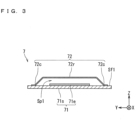
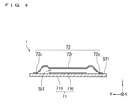
- FIG. 3 and FIG. 4 are each a cross-sectional diagram schematically illustrating an example of a configuration of the grating light valve.
- a first direction along a main surface (also referred to as a first main surface) Sf1 of a substrate 71s constituting the grating light valve on the +Z direction side is the +Y direction
- a second direction along the first main surface Sf1 and perpendicular to the +Y direction is the +X direction
- a third direction along the normal line to the first main surface Sf1 is the +Z direction.
- the grating light valve includes a base part 71 and a plurality of ribbon-shaped parts (also referred to as ribbon-like parts or ribbons) 72 as a plurality of grating elements that reflect the light separated by the spectroscopic element 6, for example.
- the base part 71 includes the substrate 71s and an electrode (also referred to as a reference electrode) 71e, for example.
- an electrode also referred to as a reference electrode
- As the substrate 71s a plate-like substrate such as a silicon substrate is used, for example.
- the reference electrode 71e is located along the first main surface Sf1 of the substrate 71s.
- As the reference electrode 71e a metal film formed on the first main surface Sf1 of the substrate 71s is used, for example.
- the plurality of ribbons 72 are located on the first main surface Sf1 of the substrate 71s.
- a fine structure configured with an amorphous silicon nitride film or the like is used, for example.
- the plurality of ribbons 72 are arrayed along the X direction.
- the number of the plurality of ribbons 72 is set to approximately from 2000 to 4000, for example. More specifically, the number of the plurality of ribbons 72 is set to approximately 3000, for example.
- the plurality of ribbons 72 are not in contact with each other. In other words, a fine clearance is present between two adjacent ribbons 72 of the plurality of ribbons 72.
- Each of the plurality of ribbons 72 has an elongated ribbon-like shape extending along the Y direction.
- each of the plurality of ribbons 72 has a rectangular shape having a transverse direction along the X direction and a longitudinal direction along the Y direction.
- the length (also referred to as width) of each ribbon 72 in the transverse direction is set to approximately from 2 micrometers ( ⁇ m) to 25.5 ⁇ m, for example, and the length of each ribbon 72 in the longitudinal direction is set to approximately from 1 millimeter (mm) to 3 mm, for example.
- Each of the plurality of ribbons 72 includes a reflection part 72r and connection parts 72c, for example.
- the reflection part 72r is located at the center in the Y direction, and the connection parts 72c are located at both ends in the Y direction.
- the connection part (also referred to as a first connection part) 72c, the reflection part 72r, and the connection part (also referred to as a second connection part) 72c are located in the mentioned order.
- the reflection part 72r includes a surface (also referred to as a light reflecting surface) that specularly reflects light on an opposite side of the base part 71.
- the light reflecting surface is a surface in parallel to the XY plane.
- the surface of each ribbon 72 has a configuration of being covered with a metal thin film, such as aluminum, that specularly reflects light. Consequently, for example, the surface of the reflection part 72r of each ribbon 72 on the opposite side of the base part 71 has a function as the light reflecting surface.
- the reflection part 72r of each ribbon 72 can reflect the light separated by the spectroscopic element 6.
- the plurality of ribbons 72 as the plurality of grating elements can reflect the light separated by the spectroscopic element 6.
- the metal thin film constituting the surface of each ribbon 72 has a function as an electrode (also referred to as a movable electrode).
- connection parts 72c are parts connected to the base part 71.
- each of the plurality of ribbons 72 includes the connection parts 72c connected to the base part 71 at both end portions in the Y direction.
- each of the plurality of ribbons 72 is connected to the first main surface Sf1 of the base part 71 at both end portions in the Y direction.
- the reflection part 72r of each of the plurality of ribbons 72 faces the base part 71 across a space Sp1. Further, the reflection part 72r of each ribbon 72 faces the reference electrode 71e of the base part 71 across the space Sp1. In other words, the reference electrode 71e of the base part 71 faces the reflection part 72r of each of the plurality of ribbons 72. From another point of view, for example, each of the plurality of ribbons 72 is provided to stretch over the substrate 71s in a manner of crossing the reference electrode 71e without coming in contact with the reference electrode 71e.
- Each of the plurality of ribbons 72 has flexibility.
- a potential difference is applied between the ribbon 72 having a function as the movable electrode and the reference electrode 71e
- an electrostatic force that attracts the reflection part 72r to the reference electrode 71e is generated between the reflection part 72r and the reference electrode 71e.
- the electrostatic force deflects the ribbon 72.
- FIG. 3 illustrates the ribbon 72 in an undeflected state (also referred to as a reference state)
- FIG. 4 illustrates the ribbon 72 in a deflected state.
- the ribbon 72 when being deflected, the ribbon 72 is displaced in the Z direction.
- the reflection part 72r is displaced in the -Z direction.
- the grating light valve as the spatial phase modulating element 7 deflects the ribbon 72 using the electrostatic force according to a signal from the first controller 10, and thereby displaces the ribbon 72 by a displacement amount according to the signal, for example.
- the grating light valve includes a complementary metal oxide semiconductor (CMOS) driver (not illustrated) or the like for individually applying a potential to each of the plurality of ribbons 72 according to the signal from the first controller 10, for example.
- CMOS complementary metal oxide semiconductor
- the first controller 10 adjusts the potential difference to be applied between the reflection part 72r and the reference electrode 71e, and can thereby deflect the ribbon 72 using the electrostatic force between the reflection part 72r and the reference electrode 71e and control displacement of the reflection part 72r with respect to the base part 71.
- a fixed reference first potential such as from 0 volts (V) to -12 V
- a second potential which is equal to or higher than the first potential
- the second potential is set such that a difference (potential difference) between the second potential and the first potential becomes a desired potential difference within a predetermined range, such as from 0 V to 25 V, for example.
- the second potential is a variable potential.
- the second potentials different from each other may be applied to the plurality of ribbons 72, for example. For example, this can freely make a difference in the displacement amount of the reflection part 72r among the plurality of ribbons 72.
- FIG. 5 illustrates an example of a first state in which the displacement amounts of the plurality of reflection parts 72r in the plurality of ribbons 72 are equally zero.
- the light reflecting surfaces of the plurality of reflection parts 72r are located along the grating surface P0, and the grating light valve as the spatial phase modulating element 7 functions as a mirror.
- the reference optical path Ln0 is an optical path along the normal line to the light reflecting surfaces of the reflection parts 72r, for example.
- the reference optical path Ln0 is an optical path along the normal line to the grating surface P0 of the grating light valve as the spatial phase modulating element 7.
- the grating surface P0 of the grating light valve is a surface along the XY plane.
- the normal line to the grating surface P0 is an imaginary straight line extending along the Z direction.
- FIG. 6 illustrates an example of a second state in which the displacement amounts of the reflection parts 72r periodically change in the X direction, and the grating light valve as the spatial phase modulating element 7 functions as a blazed diffraction grating.
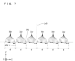
- FIG. 7 illustrates an example of a third state in which the displacement amounts of the reflection parts 72r periodically change in the X direction, and the grating light valve as the spatial phase modulating element 7 functions as a blazed diffraction grating.
- a pitch (also referred to as a grating pitch) d of the grating being a period of displace and an angle (also referred to as a blaze angle) ⁇ b formed by a sawtooth-shaped inclined surface with respect to the grating surface P0 in the blazed diffraction grating are provided.
- the grating pitch d and the blaze angle ⁇ b are different between the second state illustrated in FIG. 6 and the third state illustrated in FIG. 7 .
- the grating light valve as the spatial phase modulating element 7 may function as the blazed diffraction grating having a variable grating pitch d and blaze angle ⁇ b.
- the spectroscopic element 6 is disposed to emit light at different angles according to wavelengths in the X direction as the second direction in which the plurality of ribbons 72 as the plurality of grating elements are arrayed. Further, the spectroscopic element 6 is disposed such that the light emitted in a separated manner is radiated to the plurality of ribbons 72 as the plurality of grating elements. For example, the light emitted from the spectroscopic element 6 is radiated to a center portion of each of the plurality of ribbons 72 as the plurality of grating elements in the Y direction as the first direction.
- the light emitted from the spectroscopic element 6 is radiated to the plurality of reflection parts 72r constituting the plurality of ribbons 72 as the plurality of grating elements.
- the light emitted from the spectroscopic element 6 is radiated to a linear or band-like region along substantially the center of the plurality of ribbons 72 as the plurality of grating elements in the Y direction as the first direction.
- light having different wavelengths in the X direction is radiated to the light reflecting surfaces of the plurality of reflection parts 72r.
- the wavelengths of the light are shorter in the +X direction regarding the light emitted from the spectroscopic element 6 and radiated to the light reflecting surfaces of the plurality of reflection parts 72r.
- the grating light valve as the spatial phase modulating element 7 can relatively displace at least a part of the ribbons 72 out of the plurality of ribbons 72 as the plurality of grating elements with respect to the base part 71. Further, for example, the grating light valve as the spatial phase modulating element 7 can perform phase modulation on the light separated by the spectroscopic element 6, and emit diffracted light toward the spectroscopic element 6 along an optical path (also referred to as an incident optical path) Li of incident light from the spectroscopic element 6 regarding a part of the wavelengths within the predetermined wavelength range of the light separated by the spectroscopic element 6. Consequently, the grating light valve as the spatial phase modulating element 7 can selectively send light having a part of the wavelengths (also referred to as selected wavelengths) out of the light separated by the spectroscopic element 6 back to the spectroscopic element 6.
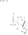
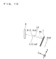
- FIG. 8 to FIG. 10 are each a diagram schematically illustrating an example of a relationship between the optical path (incident optical path) Li of the incident light and an optical path (also referred to as an emission optical path) Le of diffracted light as emission light in the grating light valve.
- the grating light valve as the spatial phase modulating element 7 can emit diffracted light at an angle according to the grating pitch d, depending on radiation of the incident light, for example.
- the grating light valve as the spatial phase modulating element 7 functions as the blazed diffraction grating and is set to the so-called Littrow configuration, regarding the light of a desired wavelength, an angle (also referred to as an angle of incidence) ⁇ i formed by a normal line L0 to the grating surface P0 and the optical path (incident optical path) Li of the incident light and an angle (also referred to as an angle of diffraction) ⁇ e formed by the normal line L0 to the grating surface P0 and the optical path (emission optical path) Le of the diffracted light are equal to each other.
- the angle of incidence ⁇ i, the angle of diffraction ⁇ e, and the blaze angle ⁇ b are equal to each other.
- whether the blaze angle ⁇ b is positive or negative can be defined in such a manner that the blaze angle ⁇ b is a negative angle when the sawtooth-shaped inclined surface is, in the +X direction, inclined toward the -Z direction and the blaze angle ⁇ b is a positive angle when the sawtooth-shaped inclined surface is, in the -X direction, inclined toward the -Z direction.
- whether the angle of incidence ⁇ i and the angle of diffraction ⁇ e are positive or negative can be defined in such a manner that the angle of incidence ⁇ i and the angle of diffraction ⁇ e are negative angles when the incident optical path Li and the emission optical path Le are inclined counterclockwise to form acute angles with respect to the normal line L0 and the angle of incidence ⁇ i and the angle of diffraction ⁇ e are positive angles when the incident optical path Li and the emission optical path Le are inclined clockwise to form acute angles with respect to the normal line L0.
- the grating light valve as the spatial phase modulating element 7 relatively displaces at least a part of the reflection parts 72r out of the plurality of reflection parts 72r with respect to the base part 71, and may thereby be set to the Littrow configuration for a part of the wavelengths (selected wavelengths) within the predetermined wavelength range of the light separated by the spectroscopic element 6.
- the grating light valve as the spatial phase modulating element 7 can emit diffracted light toward the spectroscopic element 6 along the incident optical path Li of the incident light from the spectroscopic element 6 regarding the selected wavelengths.
- the angle (angle of incidence) ⁇ i formed by the normal line L0 to the grating surface P0 and the optical path (incident optical path) Li of the incident light and the angle (angle of diffraction) ⁇ e formed by the normal line L0 to the grating surface P0 and the optical path (emission optical path) Le of the diffracted light are equal to each other. Consequently, the grating light valve as the spatial phase modulating element 7 can selectively send light having the part of the wavelengths (selected wavelengths) out of the light separated by the spectroscopic element 6 back to the spectroscopic element 6.
- the diffracted light having the selected wavelengths emitted from the spatial phase modulating element 7 generates light having the part of the wavelengths (selected wavelengths) within the predetermined wavelength range of the light separated by the spectroscopic element 6 in the spectroscopic element 6.
- the grating light valve as the spatial phase modulating element 7 relatively displaces at least a part of the reflection parts 72r out of the plurality of reflection parts 72r with respect to the base part 71, and may thereby be set to the Littrow configuration for a first wavelength ⁇ 1 as the part of the wavelengths (selected wavelengths) within the predetermined wavelength range of the light separated by the spectroscopic element 6.
- a first wavelength ⁇ 1 as the part of the wavelengths (selected wavelengths) within the predetermined wavelength range of the light separated by the spectroscopic element 6.
- a blaze angle (also referred to as a first blaze angle) ⁇ b1 corresponding to an angle (also referred to as a first angle of incidence) ⁇ i1 formed by an optical path (also referred to as a first incident optical path) Li1 of the first wavelength ⁇ 1 radiated from the spectroscopic element 6 toward the spatial phase modulating element 7 and the normal line L0 to the grating surface P0 is set.
- the grating light valve as the spatial phase modulating element 7 emits diffracted light having the first wavelength ⁇ 1 toward the spectroscopic element 6 along the incident optical path (first incident optical path) Li1 of the incident light having the first wavelength ⁇ 1 from the spectroscopic element 6.
- the angle (first angle of incidence) ⁇ i1 formed by the normal line L0 to the grating surface P0 and the optical path (first incident optical path) Li1 of the incident light having the first wavelength ⁇ 1 and an angle (also referred to as a first angle of diffraction) ⁇ e1 formed by the normal line L0 to the grating surface P0 and an optical path (also referred to as a first emission optical path) Le1 of the diffracted light having the first wavelength ⁇ 1 are equal to each other.
- the grating light valve as the spatial phase modulating element 7 can selectively send light having the first wavelength ⁇ 1 as the light having the part of the wavelengths (selected wavelengths) out of the light separated by the spectroscopic element 6 back to the spectroscopic element 6. Further, the diffracted light having the first wavelength ⁇ 1 emitted from the spatial phase modulating element 7 generates light having the first wavelength ⁇ 1 as the part of the wavelengths (selected wavelengths) within the predetermined wavelength range of the light separated by the spectroscopic element 6 in the spectroscopic element 6.
- the grating light valve as the spatial phase modulating element 7 relatively displaces at least a part of the reflection parts 72r out of the plurality of reflection parts 72r with respect to the base part 71, and may thereby be set to the Littrow configuration for a second wavelength ⁇ 2 as the part of the wavelengths (selected wavelengths) within the predetermined wavelength range of the light separated by the spectroscopic element 6.
- the second wavelength ⁇ 2 is different from the first wavelength ⁇ 1.
- a blaze angle (also referred to as a second blaze angle) ⁇ b2 corresponding to an angle (also referred to as a second angle of incidence) ⁇ i2 formed by an optical path (also referred to as a second incident optical path) Li2 of the second wavelength ⁇ 2 radiated from the spectroscopic element 6 toward the spatial phase modulating element 7 and the normal line L0 to the grating surface P0 is set.
- the grating light valve as the spatial phase modulating element 7 emits diffracted light having the second wavelength ⁇ 2 toward the spectroscopic element 6 along the incident optical path (second incident optical path) Li2 of the incident light having the second wavelength ⁇ 2 from the spectroscopic element 6.
- the angle (second angle of incidence) ⁇ i2 formed by the normal line L0 to the grating surface P0 and the optical path (second incident optical path) Li2 of the incident light having the second wavelength ⁇ 2 and an angle (also referred to as a second angle of diffraction) ⁇ e2 formed by the normal line L0 to the grating surface P0 and an optical path (also referred to as a second emission optical path) Le2 of the diffracted light having the second wavelength ⁇ 2 are equal to each other.
- the grating light valve as the spatial phase modulating element 7 can selectively send light having the second wavelength ⁇ 2 as the light having the part of the wavelengths (selected wavelengths) out of the light separated by the spectroscopic element 6 back to the spectroscopic element 6. Further, the diffracted light having the second wavelength ⁇ 2 emitted from the spatial phase modulating element 7 generates light having the second wavelength ⁇ 2 as the part of the wavelengths (selected wavelengths) within the predetermined wavelength range of the light separated by the spectroscopic element 6 in the spectroscopic element 6.
- the second light guide part 8 includes a first light output part 84 and a light guide portion 86, for example.
- the second light guide part 8 includes an optical fiber 81 as a light transmission part, a collimator lens 82 being an optical lens, and an optical fiber 83 as a light transmission part.
- light guided to the second light guide part 8 by the optical path change optical system 3 passes through the optical fiber 81, the collimator lens 82, and the optical fiber 83 in the mentioned order and then enters the first light output part 84.
- the first light output part 84 outputs a part of light out of the light guided to the second light guide part 8 by the optical path change optical system 3 to the outside of the second light guide part 8 as output light.
- an optical fiber coupler also referred to as a coupler
- the coupler outputs a part of light that has entered the coupler to the outside of the second light guide part 8 via an optical fiber 85 being a light transmission part, and guides the rest of the light out of the light that has entered the coupler to the light guide portion 86.
- quantity of light of the rest of the light output to the light guide portion 86 is set to be several times to several tens of times as large as quantity of light of the output light output to the outside of the second light guide part 8 via the optical fiber 85.
- the ratio between the quantity of light of the output light output to the outside of the second light guide part 8 via the optical fiber 85 and the quantity of light of the rest of the light output to the light guide portion 86 is set to "5 to 20":"95 to 80", for example.
- the ratio between the quantity of light of the output light and the quantity of light of the rest of the light is set to 10:90 or the like.
- the light guide portion 86 guides the rest of the light out of the light guided to the second light guide part 8 by the optical path change optical system 3 except the part of light (output light) output to the outside of the second light guide part 8 by the first light output part 84 toward the optical amplifier 1. Consequently, for example, the light that has entered the optical amplifier 1 is amplified by the optical amplifier 1, and is subsequently released toward the spectroscopic element 6. In other words, for example, the light having the part of the wavelengths (selected wavelengths) within the predetermined wavelength range generated in the spectroscopic element 6 according to the diffracted light emitted from the spatial phase modulating element 7 is amplified by the optical amplifier 1, and is subsequently released toward the spectroscopic element 6.
- the light guide portion 86 includes an optical fiber 861 as a light transmission part and a collimator lens 862 being an optical lens.
- light guided from the first light output part 84 to the light guide portion 86 passes through the optical fiber 861 and the collimator lens 862 in the mentioned order and then enters another end surface (also referred to as a second end surface) E2 that is different from the first end surface E1 of the optical amplifier 1. Consequently, for example, the light that has entered the second end surface E2 of the optical amplifier 1 is amplified by the optical amplifier 1, and is subsequently released toward the spectroscopic element 6.
- the light released from the optical amplifier 1 may pass through a path (also referred to as an amplification path), in which the light passes through the spectroscopic element 6, the spatial phase modulating element 7, the spectroscopic element 6, and the optical amplifier 1 in the mentioned order, a plurality of times. Consequently, for example, according to radiation of light having intensity in the predetermined wavelength range from the optical amplifier 1, light having a part of wavelengths (selected wavelengths) subjected to a plurality of times of amplification by the optical amplifier 1 is output. As a result, for example, light having high intensity in a narrow wavelength range may be output from the light source apparatus 100.
- the first controller 10 controls operation of the spatial phase modulating element 7. Specifically, the first controller 10 controls displacement of the plurality of ribbons 72 (specifically, the plurality of reflection parts 72r) as the plurality of grating elements with respect to the base part 71 in the spatial phase modulating element 7.
- the grating light valve as the spatial phase modulating element 7 changing a pattern of displacement of the plurality of ribbons 72 (specifically, the plurality of reflection parts 72r) as the plurality of grating elements with respect to the base part 71, the light having the part of the wavelengths (selected wavelengths) to be selectively sent back to the spectroscopic element 6 out of the light in the predetermined wavelength range separated by the spectroscopic element 6 can be quickly changed.
- the wavelengths of the output light output from the light source apparatus 100 after a plurality of times of amplification can be quickly switched. Therefore, for example, the wavelengths of the light emitted by the light source apparatus 100 can be quickly changed.
- the displacement amounts of the plurality of ribbons 72 (specifically, the plurality of reflection parts 72r) as the plurality of grating elements can be accurately controlled. Consequently, for example, the wavelengths of the light emitted by the light source apparatus 100 can be accurately changed.
- the first controller 10 includes a processor such as a central processing unit (CPU), a memory, and a storage, a field programmable gate array (FPGA), or the like, for example.
- a processor such as a central processing unit (CPU), a memory, and a storage, a field programmable gate array (FPGA), or the like, for example.
- the storage a non-volatile storage medium or the like that stores programs that can be executed by the CPU or the like is used, for example.
- the first controller 10 controls operation of the spatial phase modulating element 7, according to a signal, information, or the like from the control apparatus 200 outside of the light source apparatus 100, for example.
- the signal or the information input from the control apparatus 200 to the first controller 10 includes a signal or information indicating the pattern of displacement of the plurality of ribbons 72 (specifically, the plurality of reflection parts 72r) as the plurality of grating elements with respect to the base part 71 in the spatial phase modulating element 7, for example.
- control apparatus 200 various types of computers or the like, such as a personal computer including the CPU, the storage, and the like, is used, for example.
- the control apparatus 200 generates the information indicating the pattern of displacement of the plurality of ribbons 72 (specifically, the plurality of reflection parts 72r) as the plurality of grating elements with respect to the base part 71 in the spatial phase modulating element 7 according to a surface shape of the blazed diffraction grating corresponding to the light having a desired wavelength (selected wavelength) to be output from the light source apparatus 100, for example.
- the surface shape of the blazed diffraction grating corresponding to the light having a desired wavelength to be output from the light source apparatus 100 may be obtained through calculation or simulation based on relative positions and an orientation relationship between the spectroscopic element 6 and the spatial phase modulating element 7, information on spectral characteristic in the spectroscopic element 6, and the like, an experiment using the light source apparatus 100, or the like, for example.
- Elements that define the surface shape of the blazed diffraction grating include the blaze angle ⁇ b, the grating pitch d, and the like, for example.
- the first controller 10 can change the pattern of displacement of the plurality of ribbons 72 (specifically, the plurality of reflection parts 72r) as the plurality of grating elements with respect to the base part 71 from a first pattern to a second pattern, using the grating light valve as the spatial phase modulating element 7, for example.
- the grating light valve as the spatial phase modulating element 7 functions as the blazed diffraction grating having the blaze angle (first blaze angle) ⁇ b1 corresponding to the angle (first angle of incidence) ⁇ i1 formed by optical path (first incident optical path) Li1 of the incident light having the first wavelength ⁇ 1 radiated from the spectroscopic element 6 toward the spatial phase modulating element 7 and the normal line L0 to the grating surface P0.
- the grating light valve as the spatial phase modulating element 7 functions as the blazed diffraction grating having the blaze angle (second blaze angle) ⁇ b2 corresponding to the angle (second angle of incidence) ⁇ i2 formed by the optical path (second incident optical path) Li2 of the incident light having the second wavelength ⁇ 2 radiated from the spectroscopic element 6 toward the spatial phase modulating element 7 and the normal line L0 to the grating surface P0.
- the first controller 10 changes the pattern of displacement of the plurality of ribbons 72 (specifically, the plurality of reflection parts 72r) as the plurality of grating elements with respect to the base part 71 from the first pattern to the second pattern, a state in which the part of the wavelengths (selected wavelengths) within the predetermined wavelength range of the light separated by the spectroscopic element 6 includes the first wavelength ⁇ 1 is switched to a state in which the part of the wavelengths (selected wavelengths) within the predetermined wavelength range of the light separated by the spectroscopic element 6 includes the second wavelength ⁇ 2.
- the wavelengths of the output light output from the light source apparatus 100 can be randomly changed.
- the wavelengths of the light emitted by the light source apparatus 100 can be quickly changed.
- the first controller 10 may change the pattern of displacement of the plurality of ribbons 72 (specifically, the plurality of reflection parts 72r) as the plurality of grating elements with respect to the base part 71 from the first pattern to a third pattern, using the grating light valve as the spatial phase modulating element 7, for example.
- the grating light valve as the spatial phase modulating element 7 emits diffracted light toward the spectroscopic element 6 along the incident optical path Li of the incident light from the spectroscopic element 6.
- the first controller 10 changes the pattern of displacement of the plurality of ribbons 72 (specifically, the plurality of reflection parts 72r) as the plurality of grating elements with respect to the base part 71 from the first pattern to the third pattern
- the state in which the part of the wavelengths (selected wavelengths) within the predetermined wavelength range of the light separated by the spectroscopic element 6 includes the first wavelength ⁇ 1 is switched to a state in which the part of the wavelengths (selected wavelengths) within the predetermined wavelength range of the light separated by the spectroscopic element 6 includes the third wavelength ⁇ 3.
- FIG. 11 is a graph schematically showing an example of switching of the wavelengths (selected wavelengths) of the output light output from the light source apparatus 100.
- an example of a spectrum of the output light when the wavelength of the output light output from the light source apparatus 100 is the first wavelength ⁇ 1 is schematically indicated by a curved line shown in a solid line
- an example of a spectrum of the output light when the wavelength of the output light output from the light source apparatus 100 is the second wavelength ⁇ 2 is schematically indicated by a curved line shown in a one-dot chain line.
- an example of a spectrum of the output light when the wavelength of the output light output from the light source apparatus 100 is the third wavelength ⁇ 3 is schematically indicated by a curved line shown in a two-dot chain line.
- an aspect is considered that the wavelengths of the output light output from the light source apparatus 100 are quickly switched from the first wavelength ⁇ 1 to the second wavelength ⁇ 2 that is apart from the first wavelength ⁇ 1 and is smaller than the first wavelength ⁇ 1. Further, for example, an aspect is considered that the wavelengths of the output light output from the light source apparatus 100 are quickly switched from the first wavelength ⁇ 1 to the third wavelength ⁇ 3 that is apart from the first wavelength ⁇ 1 and is larger than the first wavelength ⁇ 1.
- the second wavelength ⁇ 2 and the third wavelength ⁇ 3 may be switched.
- the wavelengths of the output light output from the light source apparatus 100 can be randomly increased and decreased.
- the oscillating mirror of the MEMS described in the background art by oscillating an oscillating mirror larger than the ribbon 72 (specifically, the reflection part 72r) as the grating element in the light source apparatus 100, the wavelengths of the output light are swept.
- the oscillating mirror can only be oscillated within a range of a certain angle or larger.
- the wavelengths of the output light can be swept with the wavelengths of the output light being within a range of narrow wavelengths such as from 1 nm to less than 10 nm or the like, for example.
- the second controller 20 includes a processor such as a central processing unit (CPU), a memory, and a storage, a field programmable gate array (FPGA), or the like, for example.
- a processor such as a central processing unit (CPU), a memory, and a storage, a field programmable gate array (FPGA), or the like, for example.
- the storage a non-volatile storage medium or the like that stores programs that can be executed by the CPU or the like is used, for example.
- the second controller 20 may control the optical amplifier 1 according to a signal from the control apparatus 200, for example.
- the pattern of displacement of the plurality of ribbons 72 (specifically, the plurality of reflection parts 72r) as the plurality of grating elements with respect to the base part 71 can be changed by the grating light valve as the spatial phase modulating element 7. Consequently, for example, the light having the part of the wavelengths (selected wavelengths) to be selectively sent back to the spectroscopic element 6 out of the light in the predetermined wavelength range separated by the spectroscopic element 6 can be quickly changed.
- the wavelengths of the output light output from the light source apparatus 100 can be quickly switched after a plurality of times of amplification. Therefore, for example, the wavelengths of the light emitted by the light source apparatus 100 can be quickly changed.
- the light source apparatus 100 for example, when the pattern of displacement of the plurality of ribbons 72 (specifically, the plurality of reflection parts 72r) as the plurality of grating elements with respect to the base part 71 is changed from the first pattern to the second pattern, the state in which the part of the wavelengths (selected wavelengths) within the predetermined wavelength range of the light separated by the spectroscopic element 6 includes the first wavelength ⁇ 1 is switched to the state in which the part of the wavelengths (selected wavelengths) within the predetermined wavelength range of the light separated by the spectroscopic element 6 includes the second wavelength ⁇ 2. Consequently, for example, the wavelengths of the output light output from the light source apparatus 100 can be randomly changed. As a result, for example, the wavelengths of the light emitted by the light source apparatus 100 can be quickly changed.
- the part of the wavelengths (selected wavelengths) of the light to be selectively sent back to the spectroscopic element 6 by the grating light valve as the spatial phase modulating element 7 within the predetermined wavelength range of the light separated by the spectroscopic element 6 may include a plurality of wavelengths being different and apart from each other.
- the first controller 10 when the first controller 10 sets the pattern of displacement of the plurality of ribbons 72 (specifically, the plurality of reflection parts 72r) as the plurality of grating elements with respect to the base part 71 to the first pattern using the grating light valve as the spatial phase modulating element, the first controller 10 may selectively send light having a plurality of wavelengths being different and apart from each other within the predetermined wavelength range of the light separated by the spectroscopic element 6 back to the spectroscopic element 6 as light having the selected wavelengths.
- the wavelengths of the light selectively sent back to the spectroscopic element 6 out of the light in the predetermined wavelength range separated by the spectroscopic element 6 include the plurality of wavelengths being different and apart from each other, and therefore the light having the plurality of wavelengths being different and apart from each other can be simultaneously output from the light source apparatus 100.
- FIG. 12 is a graph schematically showing an example of a relationship between the wavelengths and the intensity regarding the output light having a plurality of wavelengths output from the light source apparatus 100.
- the plurality of wavelengths being different and apart from each other include a first-A wavelength ⁇ 1a and a first-B wavelength ⁇ 1b that are apart from each other and are in different relationships.
- the spectrum of the entire output light includes a peak (also referred to as a first-A peak) in the first-A wavelength ⁇ 1a and a peak (also referred to as a first-B peak) in the first-B wavelength ⁇ 1b.
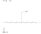
- FIG. 13 is a cross-sectional diagram schematically illustrating an example of a first-A pattern relating to the surface shape of the blazed diffraction grating functionally implemented in the grating light valve as the spatial phase modulating element 7.
- FIG. 14 is a cross-sectional diagram schematically illustrating an example of a first-B pattern relating to the surface shape of the blazed diffraction grating functionally implemented in the grating light valve as the spatial phase modulating element 7.
- the blazed diffraction grating functionally implemented in the grating light valve as the spatial phase modulating element 7 has the Littrow configuration for the first-A wavelength ⁇ 1a as the part of the wavelengths (selected wavelengths) within the predetermined wavelength range of the light separated by the spectroscopic element 6.
- the blazed diffraction grating functionally implemented in the grating light valve as the spatial phase modulating element 7 has the Littrow configuration for the first-B wavelength ⁇ 1b as the part of the wavelengths (selected wavelengths) within the predetermined wavelength range of the light separated by the spectroscopic element 6.
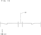
- the control apparatus 200 may generate a pattern (also referred to as a combined pattern) of the surface shape based on the surface shape of the first-A pattern and the surface shape of the first-B pattern, and generate information indicating the pattern of displacement of the plurality of ribbons 72 (specifically, the plurality of reflection parts 72r) as the plurality of grating elements with respect to the base part 71 in the spatial phase modulating element 7 according to the surface shape of the combined pattern of the blazed diffraction grating.
- the control apparatus 200 generates the combined pattern by combining the surface shape of the first-A pattern and the surface shape of the first-B pattern using the so-called inverse Fourier transform method.
- FIG. 15 is a diagram for illustrating an example of a method of generating the combined pattern for sending light having a plurality of wavelengths back to the spectroscopic element regarding the surface shape of the blazed diffraction grating functionally implemented in the grating light valve as the spatial phase modulating element 7.
- FIG. 16 is a cross-sectional diagram schematically illustrating an example of the combined pattern relating to the surface shape of the blazed diffraction grating functionally implemented in the grating light valve as the spatial phase modulating element 7.
- the control apparatus 200 generates the combined pattern so that the grating light valve as the spatial phase modulating element 7 has the surface shape of the first-A pattern at a position corresponding to a region (also referred to as a first-A region ) A1a to which the light having the first-A wavelength ⁇ 1a is radiated, and the grating light valve as the spatial phase modulating element 7 has the surface shape of the first-B pattern at a position corresponding to a region (also referred to as a first-B region) A1b to which the light having the first-B wavelength ⁇ 1b is radiated.
- the first-A wavelength ⁇ 1a and the first-B wavelength ⁇ 1b are freely set, light having any plurality of wavelengths being different and apart from each other can be simultaneously output from the light source apparatus 100.
- light having high intensity in each of a plurality of different narrow wavelength ranges can be output from the light source apparatus 100.
- FIG. 17 is a graph schematically showing an example of switching of a plurality of wavelengths of the output light output from the light source apparatus 100.
- an example of a spectrum of the output light when the wavelengths of the output light output from the light source apparatus 100 are the first-A wavelength ⁇ 1a and the first-B wavelength ⁇ 1b as the plurality of wavelengths is schematically indicated by a curved line shown in a thin two-dot chain line
- an example of a spectrum of the output light when the wavelengths of the output light output from the light source apparatus 100 are the second-A wavelength ⁇ 2a and the second-B wavelength ⁇ 2b as the plurality of wavelengths being different and apart from each other is schematically indicated by a curved line shown in a solid line.
- the spectrum of the entire output light includes a peak (also referred to as a second-A peak) in the second-A wavelength ⁇ 2a and a peak (also referred to as a second-B peak) in the second-B wavelength ⁇ 2b, for example.
- the first controller 10 changes the pattern of displacement of the plurality of ribbons 72 (specifically, the plurality of reflection parts 72r) as the plurality of grating elements with respect to the base part 71 from the first pattern to the second pattern using the grating light valve as the spatial phase modulating element 7, and may thereby switch from a state in which the plurality of wavelengths as the part of the wavelengths (selected wavelengths) within the predetermined wavelength range of the light separated by the spectroscopic element 6 include the first-A wavelength ⁇ 1a and the first-B wavelength ⁇ 1b to a state in which the plurality of wavelengths as the part of the wavelengths (selected wavelengths) within the predetermined wavelength range of the light separated by the spectroscopic element 6 include the second-A wavelength ⁇ 2a and the second-B wavelength ⁇ 2b.
- the plurality of wavelengths of the light simultaneously output from the light source apparatus 100 can be randomly changed.
- the plurality of wavelengths of the light simultaneously emitted by the light source apparatus 100 can be quickly changed.
- an aspect is considered that two wavelengths of the output light output from the light source apparatus 100 can be quickly switched from the first-A wavelength ⁇ 1a and the first-B wavelength ⁇ 1b to the second-A wavelength ⁇ 2a apart from the first-A wavelength ⁇ 1a in a direction of increasing the wavelength and the second-B wavelength ⁇ 2b apart from the first-B wavelength ⁇ 1b in a direction of increasing the wavelength.
- the second-A wavelength ⁇ 2a may be smaller than the first-A wavelength ⁇ 1a
- the second-B wavelength ⁇ 2b may be smaller than the first-B wavelength ⁇ 1b.
- the light source apparatus 100 that can quickly transform a plurality of wavelengths of simultaneously emitted light can be applied to an apparatus or a system that performs long distance high-accuracy range measurement of the Dual beat method using a beat signal of two wavelengths in a range measurement technology in the frequency modulation continuous wave (FMCW) method, for example.
- FMCW frequency modulation continuous wave
- a beat signal equivalent to a frequency difference between reference light and feedback light is detected through the use of interference between the feedback light from an object and the reference light with each ray of the reference light being swept to thereby obtain a frequency spectrum relating to the beat signal by fast Fourier transform (FFT) or the like, and thus a distance to the object is measured, for example.
- FFT fast Fourier transform
- a configuration may be employed that light may be released from the first end surface E1 of the optical amplifier 1, and light generated in the spectroscopic element 6 according to diffracted light emitted from the spatial phase modulating element 7 may be sent back to the first end surface E1 of the optical amplifier 1.
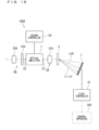
- FIG. 18 is a diagram schematically illustrating a configuration of a light source apparatus 100A according to a modification.
- a traveling direction of light is indicated by an arrow shown in a thin one-dot chain line.
- the light source apparatus 100A which is based on the light source apparatus 100 according to the first embodiment, includes a third light guide part 2A and a partially reflecting optical system 9A in place of the first light guide part 2, the optical path change optical system 3, the second light guide part 8, the optical fiber 4, and the collimator lens 5.
- the light source apparatus 100A includes the third light guide part 2A and the partially reflecting optical system 9A in addition to the optical amplifier 1, the spectroscopic element 6, the spatial phase modulating element 7, and the first controller 10. Further, the light source apparatus 100 includes the second controller 20, for example.
- the third light guide part 2A guides light released from the first end surface E1 of the optical amplifier 1 toward the spectroscopic element 6, and guides light having a part of wavelengths (selected wavelengths) generated in the spectroscopic element 6 according to diffracted light emitted from the spatial phase modulating element 7 toward the first end surface E1 of the optical amplifier 1.
- a collimator lens 21A or the like being an optical lens disposed between the optical amplifier 1 and the spectroscopic element 6 is used, for example.
- the partially reflecting optical system 9A allows a part of light out of the light released from the second end surface E2 of the optical amplifier 1 to be transmitted therethrough and outputs the part of light as output light, and reflects the rest of the light except the part of light out of the light released from the second end surface E2 of the optical amplifier 1 toward the second end surface E2 of the optical amplifier 1.
- a partially reflecting mirror 91A and a collimator lens 92A being an optical lens are used, for example.
- a semi-transparent mirror, a one-way mirror, or the like is used, for example.
- the partially reflecting mirror 91A allows a part of the light released from the second end surface E2 of the optical amplifier 1 to be transmitted therethrough, and outputs the part of light to the outside of the partially reflecting optical system 9A via the collimator lens 92A as output light.
- quantity of light of the light (rest of the light) reflected toward the second end surface E2 of the optical amplifier 1 by the partially reflecting mirror 91A out of the light released from the second end surface E2 of the optical amplifier 1 is set to be several times to several tens of times as large as quantity of light of the light (part of the light) allowed to be transmitted through the partially reflecting mirror 91A out of the light released from the second end surface E2 of the optical amplifier 1.
- the ratio between the quantity of light of the part of the light (also referred to as transmitted light) allowed to be transmitted through the partially reflecting mirror 91A and the quantity of light of the rest of the light (also referred to as reflected light) reflected by the partially reflecting mirror 91A is set to "5 to 20":"95 to 80", for example.
- the ratio between the quantity of light of the transmitted light and the quantity of light of the reflected light in the partially reflecting mirror 91A is set to 10:90 or the like.
- the light released from the optical amplifier 1 may pass through a path (also referred to as a reciprocation path), in which the light passes through the third light guide part 2A, the spectroscopic element 6, the spatial phase modulating element 7, the spectroscopic element 6, the third light guide part 2A, the optical amplifier 1, the partially reflecting optical system 9A, and the optical amplifier 1 in the mentioned order, a plurality of times.
- the light released from the optical amplifier 1 reciprocates between the partially reflecting optical system 9A and the spatial phase modulating element 7, and is subjected to a plurality of times of amplification by the optical amplifier 1.
- light having a part of wavelengths (selected wavelengths) subjected to a plurality of times of amplification by the optical amplifier 1 is output.
- light having high intensity in a narrow wavelength range may be output from the light source apparatus 100A.
- a planar light valve may be used instead of the grating light valve.
- FIG. 19 is a plan view schematically illustrating an example of a configuration of the planar light valve.
- FIG. 19 illustrates a part of a configuration of the planar light valve.
- FIG. 20 and FIG. 21 are each a cross-sectional diagram schematically illustrating a configuration of a single reflective element 74 and a base part 73 in the planar light valve. In FIG. 19 to FIG.
- a first direction along a main surface (also referred to as a second main surface) Sf2 of a substrate 73s constituting the planar light valve on the +Z direction side is the +Y direction
- a second direction along the second main surface Sf2 and perpendicular to the +Y direction is the +X direction
- a third direction along the normal line to the second main surface Sf2 is the +Z direction.
- the planar light valve as the spatial phase modulating element 7 includes a base part 73 and a plurality of reflective elements 74, for example.
- the base part 73 includes the substrate 73s and an electrode (also referred to as a reference electrode) 73e, for example.
- a plate-like substrate such as a silicon substrate is used, for example.
- the reference electrode 73e is located along the second main surface Sf2 of the substrate 73s.
- a metal film formed on the second main surface Sf2 of the substrate 73s is used, for example.
- the reference electrode 73e may be an electrode provided for each reflective element 74, or may be a common electrode for the plurality of reflective elements 74, for example.
- the plurality of reflective elements 74 are arrayed in a matrix shape. More specifically, the plurality of reflective elements 74 are arrayed on the second main surface Sf2 of the substrate 73s in a matrix shape.
- M reflective elements 74 are disposed in the Y direction and N reflective elements 74 are disposed in the X direction.
- M and N are natural numbers, and each of M and N is a numerical value from several hundreds to several thousands, for example.
- Each of the plurality of reflective elements 74 includes a movable reflection part 74r and a support part 74s.
- the plurality of movable reflection parts 74r in the plurality of reflective elements 74 function as the plurality of grating elements that reflect the light separated by the spectroscopic element 6.
- each of the plurality of reflective elements 74 includes a fixed reflection part 74f.
- the fixed reflection part 74f is a planar member having a substantially rectangular shape being fixed to the substrate 73s, and has a substantially circular opening at the center.
- a surface (also referred to as an upper surface) of the fixed reflection part 74f facing the +Z direction includes a light reflecting surface (also referred to as a fixed light reflecting surface) that specularly reflects light.
- the movable reflection part 74r includes a light reflecting surface (also referred to as a movable light reflecting surface) that specularly reflects light on an opposite side of the base part 73.
- the light reflecting surface is a surface in parallel to the XY plane.
- the surface of each movable reflection part 74r has a configuration of being covered with a metal thin film, such as aluminum, that specularly reflects light. Consequently, for example, the surface of each movable reflection part 74r on the opposite side of the base part 73 has a function as the light reflecting surface.
- each movable reflection part 74r can reflect the light separated by the spectroscopic element 6.
- the support part 74s has flexibility, and supports each of a plurality of portions of the movable reflection part 74r and is connected to the base part 73.
- a fine structure configured with an amorphous silicon nitride film or the like is used, for example.
- the support part 74s is configured with a part of a structure having a cross shape (also referred to as a cross-shaped structure), for example.
- the cross-shaped structure includes a center portion that constitutes a part of a surface (also referred to as a back surface) of the movable reflection part 74r in the -Z direction and four end portions as the support part 74s provided to stretch over between the movable reflection part 74r and the base part 73.
- the surface of the cross-shaped structure has a configuration of being covered with a metal thin film, such as aluminum.
- the metal thin film has a function as an electrode (also referred to as a movable electrode).
- the movable reflection part 74r has a function as the movable electrode.
- the movable reflection part 74r faces the base part 73 across the space Sp1. Further, each movable reflection part 74r faces the reference electrode 73e of the base part 73 reference electrode 73e of the base part 73 across the space Sp1. In other words, the reference electrode 73e of the base part 73 faces each movable reflection part 74r. Further, the support part 74s supports the movable reflection part 74r without coming in contact with the reference electrode 73e, for example. Thus, for example, when the support part 74s is deflected, as illustrated in FIG. 20 and FIG. 21 , the movable reflection part 74r may be displaced with respect to the base part 73.
- the planar light valve as the spatial phase modulating element 7 deflects the support part 74s using the electrostatic force according to a signal from the first controller 10, and thereby displaces the movable reflection part 74r by a displacement amount according to the signal, for example.
- the first controller 10 adjusts the potential difference to be applied between the movable reflection part 74r and the reference electrode 73e, and can thereby deflect the support part 74s using the electrostatic force between the movable reflection part 74r and the reference electrode 73e and control displacement of the movable reflection part 74r with respect to the base part 73.
- the first controller 10 can control displacement of the plurality of movable reflection parts 74r as the plurality of grating elements with respect to the base part 73.
- the support part 74s when the potential difference applied between the movable reflection part 74r and the reference electrode 73e reaches nearly zero after the support part 74s is deflected using the electrostatic force according to the potential difference applied between the movable reflection part 74r and the reference electrode 73e, the support part 74s returns to the undeflected reference state because of the elastic force of the support part 74s. At this time, the displacement amount of the movable reflection part 74r returns to zero.
- the displacement amounts of the respective movable reflection parts 74r in the plurality of reflective elements 74 arrayed along the Y direction are controlled to be the same.
- the displacement amounts of the movable reflection parts 74r are controlled, with the plurality of reflective elements 74 forming a row arrayed along the Y direction being one unit.
- the planar light valve may function as the blazed diffraction grating with the displacement amounts of the movable reflection parts 74r being periodically changed in the X direction in aspects similar to the second state and the third state illustrated in FIG. 6 and FIG. 7 in the grating light valve described above.
- the planar light valve as the spatial phase modulating element 7 may function as the blazed diffraction grating having a variable grating pitch d and blaze angle ⁇ b.
- the planar light valve as the spatial phase modulating element 7 can relatively displace at least a part of the movable reflection parts 74r out of the plurality of movable reflection parts 74r as the plurality of grating elements with respect to the base part 73 and thereby perform phase modulation on the light separated by the spectroscopic element 6, and emit diffracted light toward the spectroscopic element 6 along the optical path (incident optical path) Li of the incident light from the spectroscopic element 6 regarding a part of the wavelengths within the predetermined wavelength range of the light separated by the spectroscopic element 6. Consequently, the planar light valve as the spatial phase modulating element 7 can selectively send light having a part of the wavelengths (also referred to as selected wavelengths) out of the light separated by the spectroscopic element 6 back to the spectroscopic element 6.
- the planar light valve is used as the spatial phase modulating element 7, similarly to the first embodiment described above, by changing the pattern of displacement of the plurality of movable reflection parts 74r as the plurality of grating elements with respect to the base part 73, the light having the part of the wavelengths (selected wavelengths) to be selectively sent back to the spectroscopic element 6 out of the light in the predetermined wavelength range separated by the spectroscopic element 6 can be quickly changed.
- the wavelengths of the output light output from the light source apparatuses 100 and 100A after a plurality of times of amplification can be quickly switched. Therefore, for example, the wavelengths of the light emitted by the light source apparatuses 100 and 100A can be quickly changed.
- each of the plurality of movable reflection parts 74r is not limited to a disk-like shape, and upper and lower surfaces may have various plate-like shapes, such as a rectangular plate-like shape.
- the specific wavelength a wavelength at the center of the predetermined wavelength range or a wavelength around the center may be used, for example.
- the first controller 10 and the second controller 20 may be one controller.
- a part of functions of the first controller 10 and the second controller 20 may be assigned to an external apparatus of the light source apparatus 100.
- the control apparatus 200 or the like may be used, for example.
- a portion where the optical fiber is provided may be replaced with a free space as appropriate, depending on disposition of elements in front and behind the portion on the optical path.
Landscapes
- Physics & Mathematics (AREA)
- Electromagnetism (AREA)
- Spectroscopy & Molecular Physics (AREA)
- Optics & Photonics (AREA)
- General Physics & Mathematics (AREA)
- Engineering & Computer Science (AREA)
- Plasma & Fusion (AREA)
- Condensed Matter Physics & Semiconductors (AREA)
- Mechanical Light Control Or Optical Switches (AREA)
- Lasers (AREA)
- Exposure Of Semiconductors, Excluding Electron Or Ion Beam Exposure (AREA)
Abstract
Description
- The present invention relates to a light source apparatus that can change wavelengths of emission light.
- Light sources, such as laser light sources, that can change wavelengths of emission light are used in a field of optical communication, a field of inspection apparatus, and the like.
- For example, as an example of the inspection apparatus, optical coherence tomography (OCT) is known, which allows acquisition of information related to tomographic images of subjects in a non-invasive manner. In swept source OCT (SS-OCT) as a type of OCT, a light source that changes wavelengths of emission light timewise in a wide band is used, and intensity of light obtained by causing interference between sample light and reference light is acquired regarding each of the wavelengths. Thus, in SS-OCT, a wavelength swept light source (frequency swept light source) that can sweep the wavelengths of the output light in a wide band is used.
- Examples of the wavelength swept light source include an external cavity wavelength swept light source that combines a gain medium that generates light and an oscillating mirror of micro electronic mechanical systems (MEMS), and the like (for example,
Patent Document 1 and the like). In the external cavity wavelength swept light source, light having wavelengths in a certain range emitted from the gain medium is separated by a diffraction grating or the like according to the wavelengths, and light having a desired wavelength is caused to be selectively reflected and sent back to the gain medium through the use of reciprocating motion of the oscillating mirror of the MEMS, to thereby allow the light to be amplified and the wavelengths of the light emitted from the light source to be swept. - Patent Document 1:
Japanese Patent Application Laid-Open No. 2017-148109 - However, in the external cavity wavelength swept light source using the oscillating mirror of the MEMS, for example, time required for sweeping of the wavelengths of the light emitted from the light source is in accordance with the period of oscillation of the oscillating mirror of the MEMS. In other words, the rate of changing the wavelengths of the light emitted from the light source is limited depending on the period of oscillation of the oscillating mirror of the MEMS.
- Further, in the external cavity wavelength swept light source using the oscillating mirror of the MEMS, for example, due to oscillation of the oscillating mirror of the MEMS, the wavelengths of the light emitted from the light source can only be changed sequentially in a direction from a maximum wavelength toward a minimum wavelength in a predetermined wavelength range or in a direction from the minimum wavelength toward the maximum wavelength.
- Thus, regarding the external cavity wavelength swept light source, for example, there is room for improvement in quickly changing the wavelengths of emission light.
- The present invention is made in view of the problem described above, and has an object to provide a light source apparatus that can quickly change wavelengths of emission light.
- In order to solve the problem described above, a light source apparatus according to a first aspect includes an optical amplifier, a spectroscopic element, a spatial phase modulating element, and a controller. The optical amplifier is configured to amplify and release light. The spectroscopic element is configured to separate the light released from the optical amplifier according to wavelengths. The spatial phase modulating element includes a base part and a plurality of grating elements configured to reflect the light separated by the spectroscopic element. The spatial phase modulating element is configured to relatively displace at least a part of grating elements out of the plurality of grating elements with respect to the base part and thereby perform phase modulation on the light separated by the spectroscopic element, and emit diffracted light toward the spectroscopic element along an incident optical path from the spectroscopic element regarding a part of the wavelengths within a wavelength range of the light separated by the spectroscopic element. The controller is configured to control displacement of the plurality of grating elements with respect to the base part. The diffracted light emitted from the spatial phase modulating element generates the light having the part of the wavelengths in the spectroscopic element, and the light having the part of the wavelengths is amplified by the optical amplifier and is subsequently released toward the spectroscopic element. The light having the part of the wavelengths subjected to a plurality of times of amplification by the optical amplifier is output.
- A light source apparatus according to a second aspect is the light source apparatus according to the first aspect. The optical amplifier includes a semiconductor optical amplifier, a booster optical amplifier, or a semiconductor laser.
- A light source apparatus according to a third aspect is the light source apparatus according to the first or second aspect. The spectroscopic element includes a diffraction grating.
- A light source apparatus according to a fourth aspect is the light source apparatus according to any one of the first to third aspects. The controller changes a pattern of displacement of the plurality of grating elements with respect to the base part using the spatial phase modulating element from a first pattern to a second pattern, and thereby switches from a state in which the part of the wavelengths includes a first wavelength to a state in which the part of the wavelengths includes a second wavelength different from the first wavelength.
- A light source apparatus according to a fifth aspect is the light source apparatus according to any one of the first to third aspects. The part of the wavelengths includes a plurality of wavelengths being different and apart from each other.
- A light source apparatus according to a sixth aspect is the light source apparatus according to the fifth aspect. The controller changes a pattern of displacement of the plurality of grating elements with respect to the base part using the spatial phase modulating element from a first pattern to a second pattern, and thereby switches from a state in which the plurality of wavelengths include a first-A wavelength and a first-B wavelength to a state in which the plurality of wavelengths include a second-A wavelength different from the first-A wavelength and a second-B wavelength different from the first-B wavelength.
- A light source apparatus according to a seventh aspect is the light source apparatus according to any one of the first to sixth aspects, and further includes a first light guide part, an optical path change optical system, and a second light guide part. The first light guide part guides the light released from the optical amplifier toward the optical path change optical system. The optical path change optical system guides the light that has been released from the optical amplifier and has passed through the first light guide part toward the spectroscopic element, and guides the light having the part of the wavelengths generated in the spectroscopic element according to the diffracted light emitted from the spatial phase modulating element to the second light guide part. The second light guide part includes a first light output part configured to output a part of the light out of the light guided to the second light guide part by the optical path change optical system to an outside of the second light guide part, and a light guide portion configured to guide a rest of the light except the part of the light out of the light guided to the second light guide part by the optical path change optical system toward the optical amplifier.
- A light source apparatus according to an eighth aspect is the light source apparatus according to any one of the first to sixth aspects, and further includes a third light guide part and a partially reflecting optical system. The third light guide part is configured to guide the light released from a first end surface of the optical amplifier toward the spectroscopic element, and guide the light having the part of the wavelengths generated in the spectroscopic element according to the diffracted light emitted from the spatial phase modulating element toward the first end surface of the optical amplifier. The partially reflecting optical system is configured to allow a part of the light out of the light released from a second end surface of the optical amplifier to be transmitted through the partially reflecting optical system and output the part of the light, and reflect a rest of the light except the part of the light out of the light released from the second end surface of the optical amplifier toward the second end surface.
- A light source apparatus according to a ninth aspect is the light source apparatus according to any one of the first to eighth aspects. The plurality of grating elements include a plurality of ribbon-like parts. Each of the plurality of ribbon-like parts has an elongated ribbon-like shape extending along a first direction and flexibility, and includes a reflection part including a light reflecting surface on an opposite side of the base part. The plurality of ribbon-like parts are arrayed along a second direction perpendicular to the first direction. The reflection part of each of the plurality of ribbon-like parts faces the base part across a space. Each of the plurality of ribbon-like parts includes a connection part connected to the base part at both end portions in the first direction. The base part includes an electrode facing the reflection part. The controller adjusts a potential difference to be applied between the reflection part of each of the plurality of ribbon-like parts and the electrode, and thereby deflects the plurality of ribbon-like parts using an electrostatic force between the reflection part of each of the plurality of ribbon-like parts and the electrode, and controls displacement of the reflection part of each of the plurality of ribbon-like parts with respect to the base part.
- A light source apparatus according to a tenth aspect is the light source apparatus according to any one of the first to eighth aspects. The spatial phase modulating element includes a plurality of reflective elements arrayed in a matrix shape. Each of the plurality of reflective elements includes a movable reflection part facing the base part across a space and including a light reflecting surface on an opposite side of the base part, and a support part being configured to support each of a plurality of portions of the movable reflection part, being connected to the base part, and having flexibility. The plurality of grating elements include the movable reflection part of each of the plurality of reflective elements. The base part includes an electrode facing the movable reflection part. In each of the plurality of reflective elements, the controller adjusts a potential difference to be applied between the movable reflection part and the electrode and thereby deflects the support part using an electrostatic force between the movable reflection part and the electrode, and controls displacement of the movable reflection part with respect to the base part.
- In the light source apparatus according to any of the first to tenth aspects, for example, by changing the pattern of displacement of the plurality of grating elements with respect to the base part, the light of the part of the wavelengths to be selectively sent back to the spectroscopic element out of the light in the predetermined wavelength range separated by the spectroscopic element can be quickly changed. As a result, for example, the wavelengths of the output light output from the light source apparatus after a plurality of times of amplification can be quickly switched. Therefore, for example, the wavelengths of the light emitted by the light source apparatus can be quickly changed.
- In the light source apparatus according to the fourth aspect, for example, by changing the pattern of displacement of the plurality of grating elements with respect to the base part from the first pattern to the second pattern, the wavelengths of the light output from the light source apparatus can be randomly changed. As a result, for example, the wavelengths of the light emitted by the light source apparatus can be quickly changed.
- In the light source apparatus according to any of the fifth and sixth aspects, for example, the wavelengths of the light selectively sent back to the spectroscopic element out of the light in the predetermined wavelength range separated by the spectroscopic element include the plurality of wavelengths being different and apart from each other, and therefore the light having the plurality of wavelengths being different and apart from each other can be simultaneously output from the light source apparatus.
- In the light source apparatus according to the sixth aspect, for example, by changing the pattern of displacement of the plurality of grating elements with respect to the base part from the first pattern to the second pattern, the plurality of wavelengths of the light simultaneously output from the light source apparatus can be randomly changed. As a result, for example, the plurality of wavelengths of the light simultaneously emitted by the light source apparatus can be quickly changed.
-
-
FIG. 1 is a diagram schematically illustrating an example of a configuration of a light source apparatus according to a first embodiment. -
FIG. 2 is a plan view schematically illustrating an example of a configuration of a grating light valve as a spatial phase modulating element. -
FIG.3 is a cross-sectional diagram schematically illustrating an example of a configuration of the grating light valve as the spatial phase modulating element. -
FIG.4 is a cross-sectional diagram schematically illustrating an example of a configuration of the grating light valve as the spatial phase modulating element. -
FIG.5 is a diagram schematically illustrating an example of operation of the grating light valve as the spatial phase modulating element. -
FIG.6 is a diagram schematically illustrating an example of operation of the grating light valve as the spatial phase modulating element. -
FIG.7 is a diagram schematically illustrating an example of operation of the grating light valve as the spatial phase modulating element. -
FIG.8 is a diagram schematically illustrating an example of a relationship between an optical path of incident light and an optical path of diffracted light as emission light in the spatial phase modulating element. -
FIG.9 is a diagram schematically illustrating an example of a relationship between an optical path of incident light and an optical path of diffracted light as emission light in the spatial phase modulating element. -
FIG.10 is a diagram schematically illustrating an example of a relationship between an optical path of incident light and an optical path of diffracted light as emission light in the spatial phase modulating element. -
FIG.11 is a graph schematically showing an example of switching of wavelengths of output light output from the light source apparatus. -
FIG.12 is a graph schematically showing an example of a relationship between wavelengths and intensity regarding output light having a plurality of wavelengths output from the light source apparatus. -
FIG.13 is a cross-sectional diagram schematically illustrating an example of a first-A pattern relating to a surface shape of a blazed diffraction grating functionally implemented in the spatial phase modulating element. -
FIG.14 is a cross-sectional diagram schematically illustrating an example of a first-B pattern relating to the surface shape of the blazed diffraction grating functionally implemented in the spatial phase modulating element. -
FIG.15 is a diagram for illustrating an example of a method of generating a combined pattern for sending light having a plurality of wavelengths back to a spectroscopic element regarding the surface shape of the blazed diffraction grating functionally implemented in the spatial phase modulating element. -
FIG.16 is a cross-sectional diagram schematically illustrating an example of the combined pattern relating to the surface shape of the blazed diffraction grating functionally implemented in the grating light valve as the spatial phase modulating element. -
FIG.17 is a graph schematically showing an example of switching of a plurality of wavelengths of output light output from the light source apparatus. -
FIG. 18 is a diagram schematically illustrating a configuration of a light source apparatus according to a modification. -
FIG. 19 is a plan view schematically illustrating an example of a configuration of a planar light valve. -
FIG.20 is a cross-sectional diagram schematically illustrating a configuration of a single reflective element and a base part in the planar light valve. -
FIG.21 is a cross-sectional diagram schematically illustrating a configuration of the single reflective element and the base part in the planar light valve. - Various embodiments of the present invention will be described below with reference to the accompanying drawings. Constituent elements described in these embodiments are merely examples, and the scope of the present invention is not to be limited only to those. In the drawings, parts having similar configurations and functions are denoted by the same reference signs, and overlapping description will be omitted in the following description. Further, in the drawings, in order to facilitate understanding, dimensions and the number of each part are illustrated in an exaggerated or simplified manner as necessary. In each of the drawings, in order to describe positional relationships and the like of elements,
FIG. 2 to FIG. 10 ,FIG. 13 to FIG. 16 , andFIG. 19 to FIG. 21 are each provided with a right-handed XYZ orthogonal coordinate system. Here, the X-axis and the Y-axis extend in a direction along a diffraction grating surface (also referred to as a grating surface) P0 of a spatialphase modulating element 7 to be described later, and the Z-axis extends in a direction along a normal line to the grating surface P0. Further, in the following description, a direction of the point of an arrow is defined as a + (plus) direction, and a direction opposite thereto is defined as a - (minus) direction. - Unless otherwise specifically noted, an expression indicating a relative or absolute positional relationship (for example, "in a direction", "along a direction", "parallel", "orthogonal", "center", "concentric", "coaxial", or the like) does not only precisely indicate the positional relationship, but also indicates a state relatively displaced with respect to an angle or a distance as long as tolerance or comparable functionality is achieved. Unless otherwise specifically noted, an expression indicating an equivalent state (for example, "same", "equivalent", "homogeneous", or the like) does not only quantitatively precisely indicate the equivalent state, but also indicates a state in which there is a difference with which tolerance or comparable functionality is achieved. Unless otherwise specifically noted, an expression indicating a shape (for example, a "quadrilateral shape", a "cylindrical shape", or the like) does not only geometrically precisely indicate the shape, but also indicates a shape having unevenness, a chamfer, or the like, for example, as long as a comparable effect is achieved. An expression "to be provided with", "to be equipped with", "to comprise", "to include", or "to have" one constituent element is not an exclusive expression that excludes presence of another constituent element. Unless otherwise specifically noted, "on/above" and "below" may include not only a case where two elements are in contact with each other but also a case where two elements are separate from each other. Unless otherwise specifically noted, "to cause movement in a specific direction" may include not only a case of causing movement in parallel with the specific direction but also a case of causing movement in a direction having a component of the specific direction.
-
FIG. 1 is a diagram schematically illustrating an example of a configuration of alight source apparatus 100 according to a first embodiment. InFIG. 1 , a traveling direction of light is indicated by an arrow shown in a thin one-dot chain line. - The
light source apparatus 100 has a configuration of an external cavity light source apparatus, which can selectively send light having a desired wavelength out of light emitted from an optical amplifier back to the optical amplifier using a configuration provided outside the optical amplifier, to thereby amplify light having a desired wavelength and output the light. - The
light source apparatus 100 includes anoptical amplifier 1, aspectroscopic element 6, a spatialphase modulating element 7, and afirst controller 10. Further, thelight source apparatus 100 includes asecond controller 20, for example. In the first embodiment, thelight source apparatus 100 includes a firstlight guide part 2, an optical path changeoptical system 3, and a secondlight guide part 8. In the example ofFIG. 1 , thelight source apparatus 100 includes anoptical fiber 4 being a light transmission part that has a function of transmitting light and acollimator lens 5 being an optical lens, which are disposed between the optical path changeoptical system 3 and thespectroscopic element 6. - The
optical amplifier 1 amplifies and releases light. Theoptical amplifier 1 releases the light toward thespectroscopic element 6, for example. As theoptical amplifier 1, an optical gain medium (also referred to as an optical gain medium) that amplifies light is used, such as a semiconductor laser (laser diode (LD)), a semiconductor optical amplifier (SOA), or a booster optical amplifier (BOA), for example. - Further, the
optical amplifier 1 generates light in response to application of a voltage, for example. Theoptical amplifier 1 is driven when an applied voltage is controlled by control of thesecond controller 20, for example. Theoptical amplifier 1 emits light having intensity in a predetermined wavelength range, for example. The predetermined wavelength range is set to a range having a width of approximately from 50 nanometers (nm) to 150 nm, for example. The light having intensity in the predetermined wavelength range may be visible light or may be invisible light, for example. As the invisible light, near-infrared light, ultraviolet light, far-infrared light, or the like is used, for example. The light emitted from theoptical amplifier 1 may include light having intensity in a wavelength other than the predetermined wavelength range, for example. In the example ofFIG. 1 , light released from one end surface (also referred to as a first end surface) E1 of theoptical amplifier 1 passes through the firstlight guide part 2, the optical path changeoptical system 3, theoptical fiber 4, and thecollimator lens 5 in the mentioned order and is then radiated to thespectroscopic element 6. - The first
light guide part 2 guides the light released from theoptical amplifier 1 toward the optical path changeoptical system 3. The firstlight guide part 2 includes acollimator lens 21 being an optical lens and anoptical fiber 22 being a light transmission part, for example. In the example ofFIG. 1 , light released from the first end surface E1 of theoptical amplifier 1 passes through thecollimator lens 21 and theoptical fiber 22 in the mentioned order and then enters the optical path changeoptical system 3. - The optical path change
optical system 3 guides the light that has been released from theoptical amplifier 1 and has passed through the firstlight guide part 2 toward thespectroscopic element 6. Further, the optical path changeoptical system 3 guides light from thespectroscopic element 6 to the secondlight guide part 8. The light from thespectroscopic element 6 is light generated in thespectroscopic element 6 according to diffracted light emitted from the spatialphase modulating element 7, for example. As the optical path changeoptical system 3, an optical system is used which is configured using an optical circulator, a polarizing beam splitter (PBS), or the like, for example. - In the example of
FIG. 1 , light that has been released from theoptical amplifier 1 and guided toward thespectroscopic element 6 by the optical path changeoptical system 3 passes through theoptical fiber 4 and thecollimator lens 5 in the mentioned order and is then radiated to thespectroscopic element 6. Further, light generated in thespectroscopic element 6 according to diffracted light emitted from the spatialphase modulating element 7 passes through thecollimator lens 5 and theoptical fiber 4 in the mentioned order and then enters the optical path changeoptical system 3. - The
spectroscopic element 6 separates the light released from theoptical amplifier 1 according to wavelengths. In the example ofFIG. 1 , thespectroscopic element 6 separates light that has been released from theoptical amplifier 1, has passed through the firstlight guide part 2, the optical path changeoptical system 3, theoptical fiber 4, and thecollimator lens 5 in the mentioned order and been then radiated to thespectroscopic element 6, according to wavelengths. Thespectroscopic element 6 emits light having intensity in a predetermined wavelength range that constitutes the light released from theoptical amplifier 1 at angles according to wavelengths. In other words, thespectroscopic element 6 disperses the light having intensity in the predetermined wavelength range that constitutes the light released from theoptical amplifier 1 according to wavelengths. As thespectroscopic element 6, a diffraction grating is used. In the example ofFIG. 1 , a transmission type diffraction grating is used as thespectroscopic element 6; however, this is not restrictive, and a reflection type diffraction grating may be used as thespectroscopic element 6. Further, as thespectroscopic element 6, another spectroscopic element such as a prism may be used, for example. - The light separated in the
spectroscopic element 6 is radiated to the spatialphase modulating element 7. Thus, regarding the light having intensity in the predetermined wavelength range, the light is radiated to the spatialphase modulating element 7 at angles according to wavelengths. Here, an optical path serving as a reference out of optical paths of the light separated in thespectroscopic element 6 and then radiated from thespectroscopic element 6 to the spatialphase modulating element 7 is defined as a reference optical path Ln0. As the reference optical path Ln0, the central optical path of the optical paths of the light separated in thespectroscopic element 6 and then radiated from thespectroscopic element 6 to the spatialphase modulating element 7 is employed, for example. As the central optical path, regarding the light having intensity in the predetermined wavelength range, an optical path at the central angle within an angle range of the light emitted from thespectroscopic element 6 is used. - Further, the
spectroscopic element 6 generates light according to diffracted light emitted from the spatialphase modulating element 7. The light is emitted toward the optical path changeoptical system 3. In the example ofFIG. 1 , light generated in thespectroscopic element 6 according to diffracted light emitted from the spatialphase modulating element 7 passes through thecollimator lens 5 and theoptical fiber 4 in the mentioned order and then enters the optical path changeoptical system 3. - The spatial
phase modulating element 7 performs phase modulation on the light radiated from thespectroscopic element 6. Consequently, the spatialphase modulating element 7 can emit diffracted light toward thespectroscopic element 6, for example. As the spatialphase modulating element 7, a grating light valve being a type of optical phased array, which is illustrated inFIG. 2 to FIG. 4 , is used, for example.FIG. 2 is a plan view schematically illustrating an example of a configuration of the grating light valve.FIG. 2 schematically illustrates a part of a configuration of the grating light valve.FIG. 3 andFIG. 4 are each a cross-sectional diagram schematically illustrating an example of a configuration of the grating light valve.FIG. 5 to FIG. 7 are each a diagram schematically illustrating an example of operation of the grating light valve. InFIG. 2 to FIG. 7 , a first direction along a main surface (also referred to as a first main surface) Sf1 of asubstrate 71s constituting the grating light valve on the +Z direction side is the +Y direction, a second direction along the first main surface Sf1 and perpendicular to the +Y direction is the +X direction, and a third direction along the normal line to the first main surface Sf1 is the +Z direction. - The grating light valve includes a
base part 71 and a plurality of ribbon-shaped parts (also referred to as ribbon-like parts or ribbons) 72 as a plurality of grating elements that reflect the light separated by thespectroscopic element 6, for example. - The
base part 71 includes thesubstrate 71s and an electrode (also referred to as a reference electrode) 71e, for example. As thesubstrate 71s, a plate-like substrate such as a silicon substrate is used, for example. Thereference electrode 71e is located along the first main surface Sf1 of thesubstrate 71s. As thereference electrode 71e, a metal film formed on the first main surface Sf1 of thesubstrate 71s is used, for example. - The plurality of
ribbons 72 are located on the first main surface Sf1 of thesubstrate 71s. As each of the plurality ofribbons 72, a fine structure configured with an amorphous silicon nitride film or the like is used, for example. The plurality ofribbons 72 are arrayed along the X direction. The number of the plurality ofribbons 72 is set to approximately from 2000 to 4000, for example. More specifically, the number of the plurality ofribbons 72 is set to approximately 3000, for example. Here, the plurality ofribbons 72 are not in contact with each other. In other words, a fine clearance is present between twoadjacent ribbons 72 of the plurality ofribbons 72. - Each of the plurality of
ribbons 72 has an elongated ribbon-like shape extending along the Y direction. For example, as illustrated inFIG. 2 , in plan view, each of the plurality ofribbons 72 has a rectangular shape having a transverse direction along the X direction and a longitudinal direction along the Y direction. The length (also referred to as width) of eachribbon 72 in the transverse direction is set to approximately from 2 micrometers (µm) to 25.5 µm, for example, and the length of eachribbon 72 in the longitudinal direction is set to approximately from 1 millimeter (mm) to 3 mm, for example. - Each of the plurality of
ribbons 72 includes areflection part 72r andconnection parts 72c, for example. In eachribbon 72, thereflection part 72r is located at the center in the Y direction, and theconnection parts 72c are located at both ends in the Y direction. In other words, in eachribbon 72, in the Y direction, the connection part (also referred to as a first connection part) 72c, thereflection part 72r, and the connection part (also referred to as a second connection part) 72c are located in the mentioned order. - The
reflection part 72r includes a surface (also referred to as a light reflecting surface) that specularly reflects light on an opposite side of thebase part 71. For example, the light reflecting surface is a surface in parallel to the XY plane. For example, the surface of eachribbon 72 has a configuration of being covered with a metal thin film, such as aluminum, that specularly reflects light. Consequently, for example, the surface of thereflection part 72r of eachribbon 72 on the opposite side of thebase part 71 has a function as the light reflecting surface. Here, for example, owing to thereflection part 72r including the light reflecting surface, thereflection part 72r of eachribbon 72 can reflect the light separated by thespectroscopic element 6. In other words, for example, the plurality ofribbons 72 as the plurality of grating elements can reflect the light separated by thespectroscopic element 6. Further, the metal thin film constituting the surface of eachribbon 72 has a function as an electrode (also referred to as a movable electrode). - The
connection parts 72c are parts connected to thebase part 71. For example, as illustrated inFIG. 3 , each of the plurality ofribbons 72 includes theconnection parts 72c connected to thebase part 71 at both end portions in the Y direction. In other words, for example, each of the plurality ofribbons 72 is connected to the first main surface Sf1 of thebase part 71 at both end portions in the Y direction. - Here, the
reflection part 72r of each of the plurality ofribbons 72 faces thebase part 71 across a space Sp1. Further, thereflection part 72r of eachribbon 72 faces thereference electrode 71e of thebase part 71 across the space Sp1. In other words, thereference electrode 71e of thebase part 71 faces thereflection part 72r of each of the plurality ofribbons 72. From another point of view, for example, each of the plurality ofribbons 72 is provided to stretch over thesubstrate 71s in a manner of crossing thereference electrode 71e without coming in contact with thereference electrode 71e. - Each of the plurality of
ribbons 72 has flexibility. Here, for example, when a potential difference is applied between theribbon 72 having a function as the movable electrode and thereference electrode 71e, an electrostatic force that attracts thereflection part 72r to thereference electrode 71e is generated between thereflection part 72r and thereference electrode 71e. The electrostatic force deflects theribbon 72.FIG. 3 illustrates theribbon 72 in an undeflected state (also referred to as a reference state), andFIG. 4 illustrates theribbon 72 in a deflected state. As illustrated inFIG. 3 andFIG. 4 , when being deflected, theribbon 72 is displaced in the Z direction. Here, for example, when theribbon 72 is deflected with reference to a position of thereflection part 72r in the reference state in which theribbon 72 is not deflected, thereflection part 72r is displaced in the -Z direction. - The grating light valve as the spatial
phase modulating element 7 deflects theribbon 72 using the electrostatic force according to a signal from thefirst controller 10, and thereby displaces theribbon 72 by a displacement amount according to the signal, for example. The grating light valve includes a complementary metal oxide semiconductor (CMOS) driver (not illustrated) or the like for individually applying a potential to each of the plurality ofribbons 72 according to the signal from thefirst controller 10, for example. - In the first embodiment, for example, regarding each of the plurality of
ribbons 72, thefirst controller 10 adjusts the potential difference to be applied between thereflection part 72r and thereference electrode 71e, and can thereby deflect theribbon 72 using the electrostatic force between thereflection part 72r and thereference electrode 71e and control displacement of thereflection part 72r with respect to thebase part 71. - For example, a fixed reference first potential, such as from 0 volts (V) to -12 V, is applied to the
reference electrode 71e, and a second potential, which is equal to or higher than the first potential, is applied to each of the plurality ofribbons 72. The second potential is set such that a difference (potential difference) between the second potential and the first potential becomes a desired potential difference within a predetermined range, such as from 0 V to 25 V, for example. For example, the second potential is a variable potential. The second potentials different from each other may be applied to the plurality ofribbons 72, for example. For example, this can freely make a difference in the displacement amount of thereflection part 72r among the plurality ofribbons 72. When the potential difference applied between theribbon 72 and thereference electrode 71e reaches nearly zero after theribbon 72 is deflected using the electrostatic force according to the potential difference applied between theribbon 72 and thereference electrode 71e, theribbon 72 returns to the undeflected reference state because of the elastic force of theribbon 72. At this time, the displacement amount of thereflection part 72r returns to zero. -
FIG. 5 illustrates an example of a first state in which the displacement amounts of the plurality ofreflection parts 72r in the plurality ofribbons 72 are equally zero. In this case, the light reflecting surfaces of the plurality ofreflection parts 72r are located along the grating surface P0, and the grating light valve as the spatialphase modulating element 7 functions as a mirror. The reference optical path Ln0 is an optical path along the normal line to the light reflecting surfaces of thereflection parts 72r, for example. In this case, the reference optical path Ln0 is an optical path along the normal line to the grating surface P0 of the grating light valve as the spatialphase modulating element 7. Here, the grating surface P0 of the grating light valve is a surface along the XY plane. The normal line to the grating surface P0 is an imaginary straight line extending along the Z direction. -
FIG. 6 illustrates an example of a second state in which the displacement amounts of thereflection parts 72r periodically change in the X direction, and the grating light valve as the spatialphase modulating element 7 functions as a blazed diffraction grating.FIG. 7 illustrates an example of a third state in which the displacement amounts of thereflection parts 72r periodically change in the X direction, and the grating light valve as the spatialphase modulating element 7 functions as a blazed diffraction grating. In each ofFIG. 6 andFIG. 7 , for the sake of convenience, a pitch (also referred to as a grating pitch) d of the grating being a period of displace and an angle (also referred to as a blaze angle) θb formed by a sawtooth-shaped inclined surface with respect to the grating surface P0 in the blazed diffraction grating are provided. - The grating pitch d and the blaze angle θb are different between the second state illustrated in
FIG. 6 and the third state illustrated inFIG. 7 . For example, when deflection amounts of the plurality ofribbons 72 are controlled by control on the second potential to be applied to each of the plurality ofribbons 72, the grating light valve as the spatialphase modulating element 7 may function as the blazed diffraction grating having a variable grating pitch d and blaze angle θb. - In the first embodiment, for example, the
spectroscopic element 6 is disposed to emit light at different angles according to wavelengths in the X direction as the second direction in which the plurality ofribbons 72 as the plurality of grating elements are arrayed. Further, thespectroscopic element 6 is disposed such that the light emitted in a separated manner is radiated to the plurality ofribbons 72 as the plurality of grating elements. For example, the light emitted from thespectroscopic element 6 is radiated to a center portion of each of the plurality ofribbons 72 as the plurality of grating elements in the Y direction as the first direction. In other words, the light emitted from thespectroscopic element 6 is radiated to the plurality ofreflection parts 72r constituting the plurality ofribbons 72 as the plurality of grating elements. Here, the light emitted from thespectroscopic element 6 is radiated to a linear or band-like region along substantially the center of the plurality ofribbons 72 as the plurality of grating elements in the Y direction as the first direction. In this case, light having different wavelengths in the X direction is radiated to the light reflecting surfaces of the plurality ofreflection parts 72r. For example, an aspect is considered that the wavelengths of the light are shorter in the +X direction regarding the light emitted from thespectroscopic element 6 and radiated to the light reflecting surfaces of the plurality ofreflection parts 72r. - Here, for example, the grating light valve as the spatial
phase modulating element 7 can relatively displace at least a part of theribbons 72 out of the plurality ofribbons 72 as the plurality of grating elements with respect to thebase part 71. Further, for example, the grating light valve as the spatialphase modulating element 7 can perform phase modulation on the light separated by thespectroscopic element 6, and emit diffracted light toward thespectroscopic element 6 along an optical path (also referred to as an incident optical path) Li of incident light from thespectroscopic element 6 regarding a part of the wavelengths within the predetermined wavelength range of the light separated by thespectroscopic element 6. Consequently, the grating light valve as the spatialphase modulating element 7 can selectively send light having a part of the wavelengths (also referred to as selected wavelengths) out of the light separated by thespectroscopic element 6 back to thespectroscopic element 6. -
FIG. 8 to FIG. 10 are each a diagram schematically illustrating an example of a relationship between the optical path (incident optical path) Li of the incident light and an optical path (also referred to as an emission optical path) Le of diffracted light as emission light in the grating light valve. - When functioning as the blazed diffraction grating, the grating light valve as the spatial
phase modulating element 7 can emit diffracted light at an angle according to the grating pitch d, depending on radiation of the incident light, for example. Further, for example, when the grating light valve as the spatialphase modulating element 7 functions as the blazed diffraction grating and is set to the so-called Littrow configuration, regarding the light of a desired wavelength, an angle (also referred to as an angle of incidence) θi formed by a normal line L0 to the grating surface P0 and the optical path (incident optical path) Li of the incident light and an angle (also referred to as an angle of diffraction) θe formed by the normal line L0 to the grating surface P0 and the optical path (emission optical path) Le of the diffracted light are equal to each other. In the Littrow configuration, for example, as depth (= d × tan θb) of the sawtooth-like pattern of the blazed diffraction grating is closer to a half of the desired wavelength, diffraction efficiency may be increased. In this case, for example, the angle of incidence θi, the angle of diffraction θe, and the blaze angle θb are equal to each other. - Here, for example, whether the blaze angle θb is positive or negative can be defined in such a manner that the blaze angle θb is a negative angle when the sawtooth-shaped inclined surface is, in the +X direction, inclined toward the -Z direction and the blaze angle θb is a positive angle when the sawtooth-shaped inclined surface is, in the -X direction, inclined toward the -Z direction. In this case, in plan view in the +Y direction, whether the angle of incidence θi and the angle of diffraction θe are positive or negative can be defined in such a manner that the angle of incidence θi and the angle of diffraction θe are negative angles when the incident optical path Li and the emission optical path Le are inclined counterclockwise to form acute angles with respect to the normal line L0 and the angle of incidence θi and the angle of diffraction θe are positive angles when the incident optical path Li and the emission optical path Le are inclined clockwise to form acute angles with respect to the normal line L0.
- For example, in accordance with control of the
first controller 10, the grating light valve as the spatialphase modulating element 7 relatively displaces at least a part of thereflection parts 72r out of the plurality ofreflection parts 72r with respect to thebase part 71, and may thereby be set to the Littrow configuration for a part of the wavelengths (selected wavelengths) within the predetermined wavelength range of the light separated by thespectroscopic element 6. In this case, the grating light valve as the spatialphase modulating element 7 can emit diffracted light toward thespectroscopic element 6 along the incident optical path Li of the incident light from thespectroscopic element 6 regarding the selected wavelengths. In other words, regarding light having the selected wavelengths, the angle (angle of incidence) θi formed by the normal line L0 to the grating surface P0 and the optical path (incident optical path) Li of the incident light and the angle (angle of diffraction) θe formed by the normal line L0 to the grating surface P0 and the optical path (emission optical path) Le of the diffracted light are equal to each other. Consequently, the grating light valve as the spatialphase modulating element 7 can selectively send light having the part of the wavelengths (selected wavelengths) out of the light separated by thespectroscopic element 6 back to thespectroscopic element 6. Further, the diffracted light having the selected wavelengths emitted from the spatialphase modulating element 7 generates light having the part of the wavelengths (selected wavelengths) within the predetermined wavelength range of the light separated by thespectroscopic element 6 in thespectroscopic element 6. - Here, for example, in accordance with control of the
first controller 10, the grating light valve as the spatialphase modulating element 7 relatively displaces at least a part of thereflection parts 72r out of the plurality ofreflection parts 72r with respect to thebase part 71, and may thereby be set to the Littrow configuration for a first wavelength λ1 as the part of the wavelengths (selected wavelengths) within the predetermined wavelength range of the light separated by thespectroscopic element 6. Here, for example, as illustrated inFIG. 9 , in the grating light valve as the spatialphase modulating element 7, a blaze angle (also referred to as a first blaze angle) θb1 corresponding to an angle (also referred to as a first angle of incidence) θi1 formed by an optical path (also referred to as a first incident optical path) Li1 of the first wavelength λ1 radiated from thespectroscopic element 6 toward the spatialphase modulating element 7 and the normal line L0 to the grating surface P0 is set. In this case, the grating light valve as the spatialphase modulating element 7 emits diffracted light having the first wavelength λ1 toward thespectroscopic element 6 along the incident optical path (first incident optical path) Li1 of the incident light having the first wavelength λ1 from thespectroscopic element 6. In other words, regarding light having the selected wavelengths, the angle (first angle of incidence) θi1 formed by the normal line L0 to the grating surface P0 and the optical path (first incident optical path) Li1 of the incident light having the first wavelength λ1 and an angle (also referred to as a first angle of diffraction) θe1 formed by the normal line L0 to the grating surface P0 and an optical path (also referred to as a first emission optical path) Le1 of the diffracted light having the first wavelength λ1 are equal to each other. Consequently, the grating light valve as the spatialphase modulating element 7 can selectively send light having the first wavelength λ1 as the light having the part of the wavelengths (selected wavelengths) out of the light separated by thespectroscopic element 6 back to thespectroscopic element 6. Further, the diffracted light having the first wavelength λ1 emitted from the spatialphase modulating element 7 generates light having the first wavelength λ1 as the part of the wavelengths (selected wavelengths) within the predetermined wavelength range of the light separated by thespectroscopic element 6 in thespectroscopic element 6. - Further, here, for example, in accordance with control of the
first controller 10, the grating light valve as the spatialphase modulating element 7 relatively displaces at least a part of thereflection parts 72r out of the plurality ofreflection parts 72r with respect to thebase part 71, and may thereby be set to the Littrow configuration for a second wavelength λ2 as the part of the wavelengths (selected wavelengths) within the predetermined wavelength range of the light separated by thespectroscopic element 6. The second wavelength λ2 is different from the first wavelength λ1. Here, for example, as illustrated inFIG. 10 , in the grating light valve as the spatialphase modulating element 7, a blaze angle (also referred to as a second blaze angle) θb2 corresponding to an angle (also referred to as a second angle of incidence) θi2 formed by an optical path (also referred to as a second incident optical path) Li2 of the second wavelength λ2 radiated from thespectroscopic element 6 toward the spatialphase modulating element 7 and the normal line L0 to the grating surface P0 is set. In this case, the grating light valve as the spatialphase modulating element 7 emits diffracted light having the second wavelength λ2 toward thespectroscopic element 6 along the incident optical path (second incident optical path) Li2 of the incident light having the second wavelength λ2 from thespectroscopic element 6. In other words, regarding light having the selected wavelengths, the angle (second angle of incidence) θi2 formed by the normal line L0 to the grating surface P0 and the optical path (second incident optical path) Li2 of the incident light having the second wavelength λ2 and an angle (also referred to as a second angle of diffraction) θe2 formed by the normal line L0 to the grating surface P0 and an optical path (also referred to as a second emission optical path) Le2 of the diffracted light having the second wavelength λ2 are equal to each other. Consequently, the grating light valve as the spatialphase modulating element 7 can selectively send light having the second wavelength λ2 as the light having the part of the wavelengths (selected wavelengths) out of the light separated by thespectroscopic element 6 back to thespectroscopic element 6. Further, the diffracted light having the second wavelength λ2 emitted from the spatialphase modulating element 7 generates light having the second wavelength λ2 as the part of the wavelengths (selected wavelengths) within the predetermined wavelength range of the light separated by thespectroscopic element 6 in thespectroscopic element 6. - The second
light guide part 8 includes a firstlight output part 84 and alight guide portion 86, for example. In the example ofFIG. 1 , the secondlight guide part 8 includes anoptical fiber 81 as a light transmission part, acollimator lens 82 being an optical lens, and anoptical fiber 83 as a light transmission part. For example, light guided to the secondlight guide part 8 by the optical path changeoptical system 3 passes through theoptical fiber 81, thecollimator lens 82, and theoptical fiber 83 in the mentioned order and then enters the firstlight output part 84. - The first
light output part 84 outputs a part of light out of the light guided to the secondlight guide part 8 by the optical path changeoptical system 3 to the outside of the secondlight guide part 8 as output light. As the firstlight output part 84, an optical fiber coupler (also referred to as a coupler) is used, for example. For example, the coupler outputs a part of light that has entered the coupler to the outside of the secondlight guide part 8 via anoptical fiber 85 being a light transmission part, and guides the rest of the light out of the light that has entered the coupler to thelight guide portion 86. Here, for example, regarding the light that has entered the coupler, quantity of light of the rest of the light output to thelight guide portion 86 is set to be several times to several tens of times as large as quantity of light of the output light output to the outside of the secondlight guide part 8 via theoptical fiber 85. From another point of view, for example, regarding the light that has entered the coupler, the ratio between the quantity of light of the output light output to the outside of the secondlight guide part 8 via theoptical fiber 85 and the quantity of light of the rest of the light output to thelight guide portion 86 is set to "5 to 20":"95 to 80", for example. For example, the ratio between the quantity of light of the output light and the quantity of light of the rest of the light is set to 10:90 or the like. - The
light guide portion 86 guides the rest of the light out of the light guided to the secondlight guide part 8 by the optical path changeoptical system 3 except the part of light (output light) output to the outside of the secondlight guide part 8 by the firstlight output part 84 toward theoptical amplifier 1. Consequently, for example, the light that has entered theoptical amplifier 1 is amplified by theoptical amplifier 1, and is subsequently released toward thespectroscopic element 6. In other words, for example, the light having the part of the wavelengths (selected wavelengths) within the predetermined wavelength range generated in thespectroscopic element 6 according to the diffracted light emitted from the spatialphase modulating element 7 is amplified by theoptical amplifier 1, and is subsequently released toward thespectroscopic element 6. - In the example of
FIG. 1 , thelight guide portion 86 includes anoptical fiber 861 as a light transmission part and acollimator lens 862 being an optical lens. In this case, for example, light guided from the firstlight output part 84 to thelight guide portion 86 passes through theoptical fiber 861 and thecollimator lens 862 in the mentioned order and then enters another end surface (also referred to as a second end surface) E2 that is different from the first end surface E1 of theoptical amplifier 1. Consequently, for example, the light that has entered the second end surface E2 of theoptical amplifier 1 is amplified by theoptical amplifier 1, and is subsequently released toward thespectroscopic element 6. - In the
light source apparatus 100, the light released from theoptical amplifier 1 may pass through a path (also referred to as an amplification path), in which the light passes through thespectroscopic element 6, the spatialphase modulating element 7, thespectroscopic element 6, and theoptical amplifier 1 in the mentioned order, a plurality of times. Consequently, for example, according to radiation of light having intensity in the predetermined wavelength range from theoptical amplifier 1, light having a part of wavelengths (selected wavelengths) subjected to a plurality of times of amplification by theoptical amplifier 1 is output. As a result, for example, light having high intensity in a narrow wavelength range may be output from thelight source apparatus 100. - The
first controller 10 controls operation of the spatialphase modulating element 7. Specifically, thefirst controller 10 controls displacement of the plurality of ribbons 72 (specifically, the plurality ofreflection parts 72r) as the plurality of grating elements with respect to thebase part 71 in the spatialphase modulating element 7. Here, for example, by the grating light valve as the spatialphase modulating element 7 changing a pattern of displacement of the plurality of ribbons 72 (specifically, the plurality ofreflection parts 72r) as the plurality of grating elements with respect to thebase part 71, the light having the part of the wavelengths (selected wavelengths) to be selectively sent back to thespectroscopic element 6 out of the light in the predetermined wavelength range separated by thespectroscopic element 6 can be quickly changed. As a result, for example, the wavelengths of the output light output from thelight source apparatus 100 after a plurality of times of amplification can be quickly switched. Therefore, for example, the wavelengths of the light emitted by thelight source apparatus 100 can be quickly changed. - In addition, for example, with each of the plurality of ribbons 72 (specifically, the plurality of
reflection parts 72r) as the plurality of grating elements being fine, the displacement amounts of the plurality of ribbons 72 (specifically, the plurality ofreflection parts 72r) as the plurality of grating elements can be accurately controlled. Consequently, for example, the wavelengths of the light emitted by thelight source apparatus 100 can be accurately changed. - The
first controller 10 includes a processor such as a central processing unit (CPU), a memory, and a storage, a field programmable gate array (FPGA), or the like, for example. As the storage, a non-volatile storage medium or the like that stores programs that can be executed by the CPU or the like is used, for example. Thefirst controller 10 controls operation of the spatialphase modulating element 7, according to a signal, information, or the like from thecontrol apparatus 200 outside of thelight source apparatus 100, for example. The signal or the information input from thecontrol apparatus 200 to thefirst controller 10 includes a signal or information indicating the pattern of displacement of the plurality of ribbons 72 (specifically, the plurality ofreflection parts 72r) as the plurality of grating elements with respect to thebase part 71 in the spatialphase modulating element 7, for example. - As the
control apparatus 200, various types of computers or the like, such as a personal computer including the CPU, the storage, and the like, is used, for example. Thecontrol apparatus 200 generates the information indicating the pattern of displacement of the plurality of ribbons 72 (specifically, the plurality ofreflection parts 72r) as the plurality of grating elements with respect to thebase part 71 in the spatialphase modulating element 7 according to a surface shape of the blazed diffraction grating corresponding to the light having a desired wavelength (selected wavelength) to be output from thelight source apparatus 100, for example. Here, the surface shape of the blazed diffraction grating corresponding to the light having a desired wavelength to be output from thelight source apparatus 100 may be obtained through calculation or simulation based on relative positions and an orientation relationship between thespectroscopic element 6 and the spatialphase modulating element 7, information on spectral characteristic in thespectroscopic element 6, and the like, an experiment using thelight source apparatus 100, or the like, for example. Elements that define the surface shape of the blazed diffraction grating include the blaze angle θb, the grating pitch d, and the like, for example. - The
first controller 10 can change the pattern of displacement of the plurality of ribbons 72 (specifically, the plurality ofreflection parts 72r) as the plurality of grating elements with respect to thebase part 71 from a first pattern to a second pattern, using the grating light valve as the spatialphase modulating element 7, for example. - Here, for example, when the pattern of displacement of the plurality of ribbons 72 (specifically, the plurality of
reflection parts 72r) as the plurality of grating elements with respect to thebase part 71 is set to the first pattern, the grating light valve as the spatialphase modulating element 7 functions as the blazed diffraction grating having the blaze angle (first blaze angle) θb1 corresponding to the angle (first angle of incidence) θi1 formed by optical path (first incident optical path) Li1 of the incident light having the first wavelength λ1 radiated from thespectroscopic element 6 toward the spatialphase modulating element 7 and the normal line L0 to the grating surface P0. Further, for example, when the pattern of displacement of the plurality of ribbons 72 (specifically, the plurality ofreflection parts 72r) as the plurality of grating elements with respect to thebase part 71 is set to the second pattern, the grating light valve as the spatialphase modulating element 7 functions as the blazed diffraction grating having the blaze angle (second blaze angle) θb2 corresponding to the angle (second angle of incidence) θi2 formed by the optical path (second incident optical path) Li2 of the incident light having the second wavelength λ2 radiated from thespectroscopic element 6 toward the spatialphase modulating element 7 and the normal line L0 to the grating surface P0. - In this case, for example, when the
first controller 10 changes the pattern of displacement of the plurality of ribbons 72 (specifically, the plurality ofreflection parts 72r) as the plurality of grating elements with respect to thebase part 71 from the first pattern to the second pattern, a state in which the part of the wavelengths (selected wavelengths) within the predetermined wavelength range of the light separated by thespectroscopic element 6 includes the first wavelength λ1 is switched to a state in which the part of the wavelengths (selected wavelengths) within the predetermined wavelength range of the light separated by thespectroscopic element 6 includes the second wavelength λ2. Thus, for example, the wavelengths of the output light output from thelight source apparatus 100 can be randomly changed. As a result, for example, the wavelengths of the light emitted by thelight source apparatus 100 can be quickly changed. - Further, the
first controller 10 may change the pattern of displacement of the plurality of ribbons 72 (specifically, the plurality ofreflection parts 72r) as the plurality of grating elements with respect to thebase part 71 from the first pattern to a third pattern, using the grating light valve as the spatialphase modulating element 7, for example. Here, for example, when the pattern of displacement of the plurality of ribbons 72 (specifically, the plurality ofreflection parts 72r) as the plurality of grating elements with respect to thebase part 71 is set to the third pattern, regarding the light having the third wavelength λ3 within the predetermined wavelength range of the light separated by thespectroscopic element 6, the grating light valve as the spatialphase modulating element 7 emits diffracted light toward thespectroscopic element 6 along the incident optical path Li of the incident light from thespectroscopic element 6. In this case, for example, when thefirst controller 10 changes the pattern of displacement of the plurality of ribbons 72 (specifically, the plurality ofreflection parts 72r) as the plurality of grating elements with respect to thebase part 71 from the first pattern to the third pattern, the state in which the part of the wavelengths (selected wavelengths) within the predetermined wavelength range of the light separated by thespectroscopic element 6 includes the first wavelength λ1 is switched to a state in which the part of the wavelengths (selected wavelengths) within the predetermined wavelength range of the light separated by thespectroscopic element 6 includes the third wavelength λ3. -
FIG. 11 is a graph schematically showing an example of switching of the wavelengths (selected wavelengths) of the output light output from thelight source apparatus 100. InFIG. 11 , an example of a spectrum of the output light when the wavelength of the output light output from thelight source apparatus 100 is the first wavelength λ1 is schematically indicated by a curved line shown in a solid line, and an example of a spectrum of the output light when the wavelength of the output light output from thelight source apparatus 100 is the second wavelength λ2 is schematically indicated by a curved line shown in a one-dot chain line. Further, inFIG. 11 , an example of a spectrum of the output light when the wavelength of the output light output from thelight source apparatus 100 is the third wavelength λ3 is schematically indicated by a curved line shown in a two-dot chain line. - As shown in
FIG. 11 , for example, an aspect is considered that the wavelengths of the output light output from thelight source apparatus 100 are quickly switched from the first wavelength λ1 to the second wavelength λ2 that is apart from the first wavelength λ1 and is smaller than the first wavelength λ1. Further, for example, an aspect is considered that the wavelengths of the output light output from thelight source apparatus 100 are quickly switched from the first wavelength λ1 to the third wavelength λ3 that is apart from the first wavelength λ1 and is larger than the first wavelength λ1. Here, the second wavelength λ2 and the third wavelength λ3 may be switched. - In this manner, in the
light source apparatus 100, for example, as described above, by selectively sending the light having the part of the wavelengths (selected wavelengths) out of the light separated by thespectroscopic element 6 back to thespectroscopic element 6 using the grating light valve as the spatialphase modulating element 7, the wavelengths of the output light output from thelight source apparatus 100 can be randomly increased and decreased. - Incidentally, for example, in the external cavity wavelength swept light source using the oscillating mirror of the MEMS described in the background art, by oscillating an oscillating mirror larger than the ribbon 72 (specifically, the
reflection part 72r) as the grating element in thelight source apparatus 100, the wavelengths of the output light are swept. Thus, for example, there is a limitation that the oscillating mirror can only be oscillated within a range of a certain angle or larger. Thus, for example, it is not easy to sweep the wavelengths of the output light within a range of narrow wavelengths, such as less than 10 nm or the like. In contrast, in thelight source apparatus 100 according to the first embodiment, by controlling the displacement amounts of the plurality of ribbons 72 (specifically, the plurality ofreflection parts 72r) as the plurality of grating elements finer than the oscillating mirror of the MEMS, the wavelengths of the output light can be swept with the wavelengths of the output light being within a range of narrow wavelengths such as from 1 nm to less than 10 nm or the like, for example. - The
second controller 20 includes a processor such as a central processing unit (CPU), a memory, and a storage, a field programmable gate array (FPGA), or the like, for example. As the storage, a non-volatile storage medium or the like that stores programs that can be executed by the CPU or the like is used, for example. Thesecond controller 20 may control theoptical amplifier 1 according to a signal from thecontrol apparatus 200, for example. - As described above, in the
light source apparatus 100 according to the first embodiment, for example, the pattern of displacement of the plurality of ribbons 72 (specifically, the plurality ofreflection parts 72r) as the plurality of grating elements with respect to thebase part 71 can be changed by the grating light valve as the spatialphase modulating element 7. Consequently, for example, the light having the part of the wavelengths (selected wavelengths) to be selectively sent back to thespectroscopic element 6 out of the light in the predetermined wavelength range separated by thespectroscopic element 6 can be quickly changed. As a result, for example, the wavelengths of the output light output from thelight source apparatus 100 can be quickly switched after a plurality of times of amplification. Therefore, for example, the wavelengths of the light emitted by thelight source apparatus 100 can be quickly changed. - Further, in the
light source apparatus 100 according to the first embodiment, for example, when the pattern of displacement of the plurality of ribbons 72 (specifically, the plurality ofreflection parts 72r) as the plurality of grating elements with respect to thebase part 71 is changed from the first pattern to the second pattern, the state in which the part of the wavelengths (selected wavelengths) within the predetermined wavelength range of the light separated by thespectroscopic element 6 includes the first wavelength λ1 is switched to the state in which the part of the wavelengths (selected wavelengths) within the predetermined wavelength range of the light separated by thespectroscopic element 6 includes the second wavelength λ2. Consequently, for example, the wavelengths of the output light output from thelight source apparatus 100 can be randomly changed. As a result, for example, the wavelengths of the light emitted by thelight source apparatus 100 can be quickly changed. - The present invention is not limited to the first embodiment described above, and various modifications, improvements, and the like can be made within the scope not departing from the gist of the present invention.
- In the first embodiment described above, for example, the part of the wavelengths (selected wavelengths) of the light to be selectively sent back to the
spectroscopic element 6 by the grating light valve as the spatialphase modulating element 7 within the predetermined wavelength range of the light separated by thespectroscopic element 6 may include a plurality of wavelengths being different and apart from each other. Here, for example, when thefirst controller 10 sets the pattern of displacement of the plurality of ribbons 72 (specifically, the plurality ofreflection parts 72r) as the plurality of grating elements with respect to thebase part 71 to the first pattern using the grating light valve as the spatial phase modulating element, thefirst controller 10 may selectively send light having a plurality of wavelengths being different and apart from each other within the predetermined wavelength range of the light separated by thespectroscopic element 6 back to thespectroscopic element 6 as light having the selected wavelengths. In this case, for example, the wavelengths of the light selectively sent back to thespectroscopic element 6 out of the light in the predetermined wavelength range separated by thespectroscopic element 6 include the plurality of wavelengths being different and apart from each other, and therefore the light having the plurality of wavelengths being different and apart from each other can be simultaneously output from thelight source apparatus 100. -
FIG. 12 is a graph schematically showing an example of a relationship between the wavelengths and the intensity regarding the output light having a plurality of wavelengths output from thelight source apparatus 100. As shown inFIG. 12 , an aspect is considered that the plurality of wavelengths being different and apart from each other include a first-A wavelength λ1a and a first-B wavelength λ1b that are apart from each other and are in different relationships. Here, for example, the spectrum of the entire output light includes a peak (also referred to as a first-A peak) in the first-A wavelength λ1a and a peak (also referred to as a first-B peak) in the first-B wavelength λ1b. -
FIG. 13 is a cross-sectional diagram schematically illustrating an example of a first-A pattern relating to the surface shape of the blazed diffraction grating functionally implemented in the grating light valve as the spatialphase modulating element 7.FIG. 14 is a cross-sectional diagram schematically illustrating an example of a first-B pattern relating to the surface shape of the blazed diffraction grating functionally implemented in the grating light valve as the spatialphase modulating element 7. - Here, for example, when the pattern of displacement of the plurality of ribbons 72 (specifically, the plurality of
reflection parts 72r) as the plurality of grating elements with respect to thebase part 71 in the grating light valve as the spatialphase modulating element 7 is the pattern of displacement corresponding to the surface shape of the first-A pattern as illustrated inFIG. 13 , the blazed diffraction grating functionally implemented in the grating light valve as the spatialphase modulating element 7 has the Littrow configuration for the first-A wavelength λ1a as the part of the wavelengths (selected wavelengths) within the predetermined wavelength range of the light separated by thespectroscopic element 6. Further, here, for example, when the pattern of displacement of the plurality of ribbons 72 (specifically, the plurality ofreflection parts 72r) as the plurality of grating elements with respect to thebase part 71 in the grating light valve as the spatialphase modulating element 7 is the pattern of displacement corresponding to the surface shape of the first-B pattern as illustrated inFIG. 14 , the blazed diffraction grating functionally implemented in the grating light valve as the spatialphase modulating element 7 has the Littrow configuration for the first-B wavelength λ1b as the part of the wavelengths (selected wavelengths) within the predetermined wavelength range of the light separated by thespectroscopic element 6. - In this case, for example, the
control apparatus 200 may generate a pattern (also referred to as a combined pattern) of the surface shape based on the surface shape of the first-A pattern and the surface shape of the first-B pattern, and generate information indicating the pattern of displacement of the plurality of ribbons 72 (specifically, the plurality ofreflection parts 72r) as the plurality of grating elements with respect to thebase part 71 in the spatialphase modulating element 7 according to the surface shape of the combined pattern of the blazed diffraction grating. Here, for example, an aspect is considered that thecontrol apparatus 200 generates the combined pattern by combining the surface shape of the first-A pattern and the surface shape of the first-B pattern using the so-called inverse Fourier transform method. -
FIG. 15 is a diagram for illustrating an example of a method of generating the combined pattern for sending light having a plurality of wavelengths back to the spectroscopic element regarding the surface shape of the blazed diffraction grating functionally implemented in the grating light valve as the spatialphase modulating element 7.FIG. 16 is a cross-sectional diagram schematically illustrating an example of the combined pattern relating to the surface shape of the blazed diffraction grating functionally implemented in the grating light valve as the spatialphase modulating element 7. - Here, for example, as illustrated in
FIG. 15 andFIG. 16 , an aspect may be employed that thecontrol apparatus 200 generates the combined pattern so that the grating light valve as the spatialphase modulating element 7 has the surface shape of the first-A pattern at a position corresponding to a region (also referred to as a first-A region ) A1a to which the light having the first-A wavelength λ1a is radiated, and the grating light valve as the spatialphase modulating element 7 has the surface shape of the first-B pattern at a position corresponding to a region (also referred to as a first-B region) A1b to which the light having the first-B wavelength λ1b is radiated. - Here, for example, when the first-A wavelength λ1a and the first-B wavelength λ1b are freely set, light having any plurality of wavelengths being different and apart from each other can be simultaneously output from the
light source apparatus 100. As a result, for example, light having high intensity in each of a plurality of different narrow wavelength ranges can be output from thelight source apparatus 100. -
FIG. 17 is a graph schematically showing an example of switching of a plurality of wavelengths of the output light output from thelight source apparatus 100. InFIG. 17 , an example of a spectrum of the output light when the wavelengths of the output light output from thelight source apparatus 100 are the first-A wavelength λ1a and the first-B wavelength λ1b as the plurality of wavelengths is schematically indicated by a curved line shown in a thin two-dot chain line, and an example of a spectrum of the output light when the wavelengths of the output light output from thelight source apparatus 100 are the second-A wavelength λ2a and the second-B wavelength λ2b as the plurality of wavelengths being different and apart from each other is schematically indicated by a curved line shown in a solid line. When the wavelengths of the output light output from thelight source apparatus 100 are the second-A wavelength λ2a and the second-B wavelength λ2b as the plurality of wavelengths being different and apart from each other, the spectrum of the entire output light includes a peak (also referred to as a second-A peak) in the second-A wavelength λ2a and a peak (also referred to as a second-B peak) in the second-B wavelength λ2b, for example. - Here, for example, the
first controller 10 changes the pattern of displacement of the plurality of ribbons 72 (specifically, the plurality ofreflection parts 72r) as the plurality of grating elements with respect to thebase part 71 from the first pattern to the second pattern using the grating light valve as the spatialphase modulating element 7, and may thereby switch from a state in which the plurality of wavelengths as the part of the wavelengths (selected wavelengths) within the predetermined wavelength range of the light separated by thespectroscopic element 6 include the first-A wavelength λ1a and the first-B wavelength λ1b to a state in which the plurality of wavelengths as the part of the wavelengths (selected wavelengths) within the predetermined wavelength range of the light separated by thespectroscopic element 6 include the second-A wavelength λ2a and the second-B wavelength λ2b. In this case, for example, by changing the pattern of displacement of the plurality of ribbons 72 (specifically, the plurality ofreflection parts 72r) as the plurality of grating elements of the grating light valve as the spatialphase modulating element 7 with respect to thebase part 71 from the first pattern to the second pattern, the plurality of wavelengths of the light simultaneously output from thelight source apparatus 100 can be randomly changed. As a result, for example, the plurality of wavelengths of the light simultaneously emitted by thelight source apparatus 100 can be quickly changed. - As shown in
FIG. 17 , for example, an aspect is considered that two wavelengths of the output light output from thelight source apparatus 100 can be quickly switched from the first-A wavelength λ1a and the first-B wavelength λ1b to the second-A wavelength λ2a apart from the first-A wavelength λ1a in a direction of increasing the wavelength and the second-B wavelength λ2b apart from the first-B wavelength λ1b in a direction of increasing the wavelength. Here, for example, the second-A wavelength λ2a may be smaller than the first-A wavelength λ1a, and the second-B wavelength λ2b may be smaller than the first-B wavelength λ1b. - Here, the
light source apparatus 100 that can quickly transform a plurality of wavelengths of simultaneously emitted light can be applied to an apparatus or a system that performs long distance high-accuracy range measurement of the Dual beat method using a beat signal of two wavelengths in a range measurement technology in the frequency modulation continuous wave (FMCW) method, for example. In long distance high-accuracy range measurement of the Dual beat method, by simultaneously using light having two different wavelengths, a beat signal equivalent to a frequency difference between reference light and feedback light is detected through the use of interference between the feedback light from an object and the reference light with each ray of the reference light being swept to thereby obtain a frequency spectrum relating to the beat signal by fast Fourier transform (FFT) or the like, and thus a distance to the object is measured, for example. - In the first embodiment and the modification described above, for example, a configuration may be employed that light may be released from the first end surface E1 of the
optical amplifier 1, and light generated in thespectroscopic element 6 according to diffracted light emitted from the spatialphase modulating element 7 may be sent back to the first end surface E1 of theoptical amplifier 1. -
FIG. 18 is a diagram schematically illustrating a configuration of alight source apparatus 100A according to a modification. InFIG. 18 , similarly toFIG. 1 , a traveling direction of light is indicated by an arrow shown in a thin one-dot chain line. - The
light source apparatus 100A, which is based on thelight source apparatus 100 according to the first embodiment, includes a thirdlight guide part 2A and a partially reflectingoptical system 9A in place of the firstlight guide part 2, the optical path changeoptical system 3, the secondlight guide part 8, theoptical fiber 4, and thecollimator lens 5. In other words, thelight source apparatus 100A includes the thirdlight guide part 2A and the partially reflectingoptical system 9A in addition to theoptical amplifier 1, thespectroscopic element 6, the spatialphase modulating element 7, and thefirst controller 10. Further, thelight source apparatus 100 includes thesecond controller 20, for example. - The third
light guide part 2A guides light released from the first end surface E1 of theoptical amplifier 1 toward thespectroscopic element 6, and guides light having a part of wavelengths (selected wavelengths) generated in thespectroscopic element 6 according to diffracted light emitted from the spatialphase modulating element 7 toward the first end surface E1 of theoptical amplifier 1. As the thirdlight guide part 2A, acollimator lens 21A or the like being an optical lens disposed between theoptical amplifier 1 and thespectroscopic element 6 is used, for example. - The partially reflecting
optical system 9A allows a part of light out of the light released from the second end surface E2 of theoptical amplifier 1 to be transmitted therethrough and outputs the part of light as output light, and reflects the rest of the light except the part of light out of the light released from the second end surface E2 of theoptical amplifier 1 toward the second end surface E2 of theoptical amplifier 1. As the partially reflectingoptical system 9A, a partially reflectingmirror 91A and acollimator lens 92A being an optical lens are used, for example. As the partially reflectingmirror 91A, a semi-transparent mirror, a one-way mirror, or the like is used, for example. The partially reflectingmirror 91A allows a part of the light released from the second end surface E2 of theoptical amplifier 1 to be transmitted therethrough, and outputs the part of light to the outside of the partially reflectingoptical system 9A via thecollimator lens 92A as output light. - Here, quantity of light of the light (rest of the light) reflected toward the second end surface E2 of the
optical amplifier 1 by the partially reflectingmirror 91A out of the light released from the second end surface E2 of theoptical amplifier 1 is set to be several times to several tens of times as large as quantity of light of the light (part of the light) allowed to be transmitted through the partially reflectingmirror 91A out of the light released from the second end surface E2 of theoptical amplifier 1. From another point of view, of the light radiated from the second end surface E2 of theoptical amplifier 1 to the partially reflectingmirror 91A, the ratio between the quantity of light of the part of the light (also referred to as transmitted light) allowed to be transmitted through the partially reflectingmirror 91A and the quantity of light of the rest of the light (also referred to as reflected light) reflected by the partially reflectingmirror 91A is set to "5 to 20":"95 to 80", for example. For example, the ratio between the quantity of light of the transmitted light and the quantity of light of the reflected light in the partially reflectingmirror 91A is set to 10:90 or the like. - In the
light source apparatus 100A having the configuration described above, the light released from theoptical amplifier 1 may pass through a path (also referred to as a reciprocation path), in which the light passes through the thirdlight guide part 2A, thespectroscopic element 6, the spatialphase modulating element 7, thespectroscopic element 6, the thirdlight guide part 2A, theoptical amplifier 1, the partially reflectingoptical system 9A, and theoptical amplifier 1 in the mentioned order, a plurality of times. In other words, the light released from theoptical amplifier 1 reciprocates between the partially reflectingoptical system 9A and the spatialphase modulating element 7, and is subjected to a plurality of times of amplification by theoptical amplifier 1. Consequently, for example, according to radiation of light having intensity in the predetermined wavelength range from theoptical amplifier 1, light having a part of wavelengths (selected wavelengths) subjected to a plurality of times of amplification by theoptical amplifier 1 is output. As a result, for example, light having high intensity in a narrow wavelength range may be output from thelight source apparatus 100A. - In the first embodiment and each modification described above, for example, as the spatial
phase modulating element 7, a planar light valve may be used instead of the grating light valve. -
FIG. 19 is a plan view schematically illustrating an example of a configuration of the planar light valve.FIG. 19 illustrates a part of a configuration of the planar light valve.FIG. 20 andFIG. 21 are each a cross-sectional diagram schematically illustrating a configuration of a singlereflective element 74 and abase part 73 in the planar light valve. InFIG. 19 to FIG. 21 , a first direction along a main surface (also referred to as a second main surface) Sf2 of asubstrate 73s constituting the planar light valve on the +Z direction side is the +Y direction, a second direction along the second main surface Sf2 and perpendicular to the +Y direction is the +X direction, and a third direction along the normal line to the second main surface Sf2 is the +Z direction. InFIG. 20 andFIG. 21 , for the sake of convenience, illustration of asupport part 74s to be described later is omitted. - The planar light valve as the spatial
phase modulating element 7 includes abase part 73 and a plurality ofreflective elements 74, for example. - The
base part 73 includes thesubstrate 73s and an electrode (also referred to as a reference electrode) 73e, for example. As thesubstrate 73s, a plate-like substrate such as a silicon substrate is used, for example. Thereference electrode 73e is located along the second main surface Sf2 of thesubstrate 73s. As thereference electrode 73e, a metal film formed on the second main surface Sf2 of thesubstrate 73s is used, for example. Thereference electrode 73e may be an electrode provided for eachreflective element 74, or may be a common electrode for the plurality ofreflective elements 74, for example. - The plurality of
reflective elements 74 are arrayed in a matrix shape. More specifically, the plurality ofreflective elements 74 are arrayed on the second main surface Sf2 of thesubstrate 73s in a matrix shape. In the planar light valve, for example, Mreflective elements 74 are disposed in the Y direction and Nreflective elements 74 are disposed in the X direction. Here, M and N are natural numbers, and each of M and N is a numerical value from several hundreds to several thousands, for example. - Each of the plurality of
reflective elements 74 includes amovable reflection part 74r and asupport part 74s. Here, the plurality ofmovable reflection parts 74r in the plurality ofreflective elements 74 function as the plurality of grating elements that reflect the light separated by thespectroscopic element 6. Further, in the examples ofFIG. 19 to FIG. 21 , each of the plurality ofreflective elements 74 includes a fixedreflection part 74f. - As illustrated in
FIG. 19 to FIG. 21 , the fixedreflection part 74f is a planar member having a substantially rectangular shape being fixed to thesubstrate 73s, and has a substantially circular opening at the center. A surface (also referred to as an upper surface) of the fixedreflection part 74f facing the +Z direction includes a light reflecting surface (also referred to as a fixed light reflecting surface) that specularly reflects light. - The
movable reflection part 74r includes a light reflecting surface (also referred to as a movable light reflecting surface) that specularly reflects light on an opposite side of thebase part 73. The light reflecting surface is a surface in parallel to the XY plane. For example, the surface of eachmovable reflection part 74r has a configuration of being covered with a metal thin film, such as aluminum, that specularly reflects light. Consequently, for example, the surface of eachmovable reflection part 74r on the opposite side of thebase part 73 has a function as the light reflecting surface. Here, for example, owing to themovable reflection part 74r including the light reflecting surface, eachmovable reflection part 74r can reflect the light separated by thespectroscopic element 6. - The
support part 74s has flexibility, and supports each of a plurality of portions of themovable reflection part 74r and is connected to thebase part 73. As thesupport part 74s, a fine structure configured with an amorphous silicon nitride film or the like is used, for example. Thesupport part 74s is configured with a part of a structure having a cross shape (also referred to as a cross-shaped structure), for example. In this case, the cross-shaped structure includes a center portion that constitutes a part of a surface (also referred to as a back surface) of themovable reflection part 74r in the -Z direction and four end portions as thesupport part 74s provided to stretch over between themovable reflection part 74r and thebase part 73. The surface of the cross-shaped structure has a configuration of being covered with a metal thin film, such as aluminum. The metal thin film has a function as an electrode (also referred to as a movable electrode). In other words, themovable reflection part 74r has a function as the movable electrode. - Here, the
movable reflection part 74r faces thebase part 73 across the space Sp1. Further, eachmovable reflection part 74r faces thereference electrode 73e of thebase part 73reference electrode 73e of thebase part 73 across the space Sp1. In other words, thereference electrode 73e of thebase part 73 faces eachmovable reflection part 74r. Further, thesupport part 74s supports themovable reflection part 74r without coming in contact with thereference electrode 73e, for example. Thus, for example, when thesupport part 74s is deflected, as illustrated inFIG. 20 andFIG. 21 , themovable reflection part 74r may be displaced with respect to thebase part 73. - Here, for example, when a potential difference is applied between the
movable reflection part 74r having a function as the movable electrode and thereference electrode 73e, an electrostatic force that attracts themovable reflection part 74r to thereference electrode 73e is generated between themovable reflection part 74r and thereference electrode 73e. The electrostatic force deflects thesupport part 74s. - The planar light valve as the spatial
phase modulating element 7 deflects thesupport part 74s using the electrostatic force according to a signal from thefirst controller 10, and thereby displaces themovable reflection part 74r by a displacement amount according to the signal, for example. - For example, regarding each of the plurality of
reflective elements 74, thefirst controller 10 adjusts the potential difference to be applied between themovable reflection part 74r and thereference electrode 73e, and can thereby deflect thesupport part 74s using the electrostatic force between themovable reflection part 74r and thereference electrode 73e and control displacement of themovable reflection part 74r with respect to thebase part 73. In other words, thefirst controller 10 can control displacement of the plurality ofmovable reflection parts 74r as the plurality of grating elements with respect to thebase part 73. Note that, here, for example, when the potential difference applied between themovable reflection part 74r and thereference electrode 73e reaches nearly zero after thesupport part 74s is deflected using the electrostatic force according to the potential difference applied between themovable reflection part 74r and thereference electrode 73e, thesupport part 74s returns to the undeflected reference state because of the elastic force of thesupport part 74s. At this time, the displacement amount of themovable reflection part 74r returns to zero. - Here, the displacement amounts of the respective
movable reflection parts 74r in the plurality ofreflective elements 74 arrayed along the Y direction are controlled to be the same. In other words, regarding the plurality ofreflective elements 74 arrayed in a matrix shape, the displacement amounts of themovable reflection parts 74r are controlled, with the plurality ofreflective elements 74 forming a row arrayed along the Y direction being one unit. Thus, for example, the planar light valve may function as the blazed diffraction grating with the displacement amounts of themovable reflection parts 74r being periodically changed in the X direction in aspects similar to the second state and the third state illustrated inFIG. 6 andFIG. 7 in the grating light valve described above. Further, for example, when the deflection amounts of the plurality ofsupport parts 74s are controlled by control or the like on the potential to be applied to the movable electrode of the plurality ofmovable reflection parts 74r, the planar light valve as the spatialphase modulating element 7 may function as the blazed diffraction grating having a variable grating pitch d and blaze angle θb. - Thus, for example, the planar light valve as the spatial
phase modulating element 7 can relatively displace at least a part of themovable reflection parts 74r out of the plurality ofmovable reflection parts 74r as the plurality of grating elements with respect to thebase part 73 and thereby perform phase modulation on the light separated by thespectroscopic element 6, and emit diffracted light toward thespectroscopic element 6 along the optical path (incident optical path) Li of the incident light from thespectroscopic element 6 regarding a part of the wavelengths within the predetermined wavelength range of the light separated by thespectroscopic element 6. Consequently, the planar light valve as the spatialphase modulating element 7 can selectively send light having a part of the wavelengths (also referred to as selected wavelengths) out of the light separated by thespectroscopic element 6 back to thespectroscopic element 6. - Accordingly, also when the planar light valve is used as the spatial
phase modulating element 7, similarly to the first embodiment described above, by changing the pattern of displacement of the plurality ofmovable reflection parts 74r as the plurality of grating elements with respect to thebase part 73, the light having the part of the wavelengths (selected wavelengths) to be selectively sent back to thespectroscopic element 6 out of the light in the predetermined wavelength range separated by thespectroscopic element 6 can be quickly changed. As a result, for example, the wavelengths of the output light output from thelight source apparatuses light source apparatuses - Here, for example, the shape of each of the plurality of
movable reflection parts 74r is not limited to a disk-like shape, and upper and lower surfaces may have various plate-like shapes, such as a rectangular plate-like shape. - In the first embodiment and each modification described above, for example, the depth (= d × tan θb) of the sawtooth-like pattern of the blazed diffraction grating functionally implemented in the spatial
phase modulating element 7 need not always be set to a half of the selected wavelengths. Here, for example, the depth (= d × tan θb) of the sawtooth-like pattern of the blazed diffraction grating functionally implemented in the spatialphase modulating element 7 may be set to a half of a specific wavelength within the predetermined wavelength range. As the specific wavelength, a wavelength at the center of the predetermined wavelength range or a wavelength around the center may be used, for example. - In the first embodiment and each modification described above, for example, the
first controller 10 and thesecond controller 20 may be one controller. - In the first embodiment and each modification described above, for example, a part of functions of the
first controller 10 and thesecond controller 20 may be assigned to an external apparatus of thelight source apparatus 100. As the external apparatus, thecontrol apparatus 200 or the like may be used, for example. - In the first embodiment and each modification described above, a portion where the optical fiber is provided may be replaced with a free space as appropriate, depending on disposition of elements in front and behind the portion on the optical path.
- Note that it goes without saying that all or a part of the configurations in the first embodiment and various modifications described above can be combined as appropriate, unless there is an inconsistency.
-
- 1
- Optical amplifier
- 10
- First controller
- 100, 100A
- Light source apparatus
- 2
- First light guide part
- 20
- Second controller
- 2A
- Third light guide part
- 3
- Optical path change optical system
- 6
- Spectroscopic element
- 7
- Spatial phase modulating element
- 71, 73
- Base part
- 71e, 73e
- Reference electrode
- 71s, 73s
- Substrate
- 72
- Ribbon
- 72c
- Connection part
- 72r
- Reflection part
- 74
- Reflective element
- 74r
- Movable reflection part
- 74s
- Support part
- 8
- Second light guide part
- 84
- First light output part
- 86
- Light guide portion
- 9A
- Partially reflecting optical system
- E1
- First end surface
- E2
- Second end surface
- Li
- Incident optical path
- Sp1
- Space
Claims (10)
- A light source apparatus comprising:an optical amplifier configured to amplify and release light;a spectroscopic element configured to separate the light released from the optical amplifier according to wavelengths;a spatial phase modulating element including a base part and a plurality of grating elements configured to reflect the light separated by the spectroscopic element, the spatial phase modulating element being configured to relatively displace at least a part of grating elements out of the plurality of grating elements with respect to the base part and thereby perform phase modulation on the light separated by the spectroscopic element, and emit diffracted light toward the spectroscopic element along an incident optical path from the spectroscopic element regarding a part of the wavelengths within a wavelength range of the light separated by the spectroscopic element; anda controller configured to control displacement of the plurality of grating elements with respect to the base part, whereinthe diffracted light emitted from the spatial phase modulating element generates the light having the part of the wavelengths in the spectroscopic element, and the light having the part of the wavelengths is amplified by the optical amplifier and is subsequently released toward the spectroscopic element, andthe light having the part of the wavelengths subjected to a plurality of times of amplification by the optical amplifier is output.
- The light source apparatus according to claim 1, wherein
the optical amplifier includes a semiconductor optical amplifier, a booster optical amplifier, or a semiconductor laser. - The light source apparatus according to claim 1 or 2, wherein
the spectroscopic element includes a diffraction grating. - The light source apparatus according to any one of claims 1 to 3, wherein
the controller changes a pattern of displacement of the plurality of grating elements with respect to the base part using the spatial phase modulating element from a first pattern to a second pattern, and thereby switches from a state in which the part of the wavelengths includes a first wavelength to a state in which the part of the wavelengths includes a second wavelength different from the first wavelength. - The light source apparatus according to any one of claims 1 to 3, wherein
the part of the wavelengths includes a plurality of wavelengths being different and apart from each other. - The light source apparatus according to claim 5, wherein
the controller changes a pattern of displacement of the plurality of grating elements with respect to the base part using the spatial phase modulating element from a first pattern to a second pattern, and thereby switches from a state in which the plurality of wavelengths include a first-A wavelength and a first-B wavelength to a state in which the plurality of wavelengths include a second-A wavelength different from the first-A wavelength and a second-B wavelength different from the first-B wavelength. - The light source apparatus according to any one of claims 1 to 6, further comprising:a first light guide part;an optical path change optical system; anda second light guide part, whereinthe first light guide part guides the light released from the optical amplifier toward the optical path change optical system,the optical path change optical system guides the light that has been released from the optical amplifier and has passed through the first light guide part toward the spectroscopic element, and guides the light having the part of the wavelengths generated in the spectroscopic element according to the diffracted light emitted from the spatial phase modulating element to the second light guide part, andthe second light guide part includes a first light output part configured to output a part of the light out of the light guided to the second light guide part by the optical path change optical system to an outside of the second light guide part, and a light guide portion configured to guide a rest of the light except the part of the light out of the light guided to the second light guide part by the optical path change optical system toward the optical amplifier.
- The light source apparatus according to any one of claims 1 to 6, further comprising:a third light guide part configured to guide the light released from a first end surface of the optical amplifier toward the spectroscopic element, and guide the light having the part of the wavelengths generated in the spectroscopic element according to the diffracted light emitted from the spatial phase modulating element toward the first end surface of the optical amplifier; anda partially reflecting optical system configured to allow a part of the light out of the light released from a second end surface of the optical amplifier to be transmitted through the partially reflecting optical system and output the part of the light, and reflect a rest of the light except the part of the light out of the light released from the second end surface of the optical amplifier toward the second end surface.
- The light source apparatus according to any one of claims 1 to 8, whereinthe plurality of grating elements include a plurality of ribbon-like parts,each of the plurality of ribbon-like parts has an elongated ribbon-like shape extending along a first direction and flexibility, and includes a reflection part including a light reflecting surface on an opposite side of the base part,the plurality of ribbon-like parts are arrayed along a second direction perpendicular to the first direction,the reflection part of each of the plurality of ribbon-like parts faces the base part across a space,each of the plurality of ribbon-like parts includes a connection part connected to the base part at both end portions in the first direction,the base part includes an electrode facing the reflection part, andthe controller adjusts a potential difference to be applied between the reflection part of each of the plurality of ribbon-like parts and the electrode, and thereby deflects the plurality of ribbon-like parts using an electrostatic force between the reflection part of each of the plurality of ribbon-like parts and the electrode, and controls displacement of the reflection part of each of the plurality of ribbon-like parts with respect to the base part.
- The light source apparatus according to any one of claims 1 to 8, whereinthe spatial phase modulating element includes a plurality of reflective elements arrayed in a matrix shape,each of the plurality of reflective elements includes a movable reflection part facing the base part across a space and including a light reflecting surface on an opposite side of the base part, and a support part being configured to support each of a plurality of portions of the movable reflection part, being connected to the base part, and having flexibility,the plurality of grating elements include the movable reflection part of each of the plurality of reflective elements,the base part includes an electrode facing the movable reflection part, andin each of the plurality of reflective elements, the controller adjusts a potential difference to be applied between the movable reflection part and the electrode and thereby deflects the support part using an electrostatic force between the movable reflection part and the electrode, and controls displacement of the movable reflection part with respect to the base part.
Applications Claiming Priority (2)
| Application Number | Priority Date | Filing Date | Title |
|---|---|---|---|
| JP2022048296A JP7744276B2 (en) | 2022-03-24 | 2022-03-24 | light source device |
| PCT/JP2022/040135 WO2023181475A1 (en) | 2022-03-24 | 2022-10-27 | Light source device |
Publications (2)
| Publication Number | Publication Date |
|---|---|
| EP4503350A1 true EP4503350A1 (en) | 2025-02-05 |
| EP4503350A4 EP4503350A4 (en) | 2026-03-25 |
Family
ID=88100430
Family Applications (1)
| Application Number | Title | Priority Date | Filing Date |
|---|---|---|---|
| EP22933605.2A Pending EP4503350A4 (en) | 2022-03-24 | 2022-10-27 | LIGHT SOURCE DEVICE |
Country Status (6)
| Country | Link |
|---|---|
| US (1) | US20250189373A1 (en) |
| EP (1) | EP4503350A4 (en) |
| JP (1) | JP7744276B2 (en) |
| CN (1) | CN118872164A (en) |
| TW (1) | TWI857388B (en) |
| WO (1) | WO2023181475A1 (en) |
Family Cites Families (13)
| Publication number | Priority date | Publication date | Assignee | Title |
|---|---|---|---|---|
| US6282213B1 (en) * | 1998-09-14 | 2001-08-28 | Interscience, Inc. | Tunable diode laser with fast digital line selection |
| US6901088B2 (en) * | 2001-07-06 | 2005-05-31 | Intel Corporation | External cavity laser apparatus with orthogonal tuning of laser wavelength and cavity optical pathlength |
| US6829258B1 (en) * | 2002-06-26 | 2004-12-07 | Silicon Light Machines, Inc. | Rapidly tunable external cavity laser |
| JP2005077964A (en) * | 2003-09-03 | 2005-03-24 | Fujitsu Ltd | Spectroscope apparatus |
| JP2007242747A (en) | 2006-03-07 | 2007-09-20 | Fujifilm Corp | Tunable laser device and optical tomographic imaging apparatus |
| DE102007051520B4 (en) * | 2007-10-19 | 2021-01-14 | Seereal Technologies S.A. | Complex spatial light modulator, spatial light modulator device and method for modulating a wave field |
| US20120307257A1 (en) | 2010-02-12 | 2012-12-06 | Canon Kabushiki Kaisha | Swept light source apparatus and imaging system including the same |
| US9476824B2 (en) | 2012-10-12 | 2016-10-25 | Purdue Research Foundation | Optical chemical classification |
| JP6651768B2 (en) | 2015-09-28 | 2020-02-19 | 株式会社ニコン | Pattern drawing equipment |
| JP6679340B2 (en) | 2016-02-22 | 2020-04-15 | キヤノン株式会社 | Optical coherence tomography |
| JP6678705B2 (en) * | 2018-07-24 | 2020-04-08 | 三菱電機株式会社 | Distance measuring device |
| CN110187596B (en) | 2019-06-26 | 2021-05-04 | 业成科技(成都)有限公司 | Optical projection devices and electronic equipment |
| JP7744875B2 (en) * | 2022-05-12 | 2025-09-26 | 浜松ホトニクス株式会社 | Light source device and control method |
-
2022
- 2022-03-24 JP JP2022048296A patent/JP7744276B2/en active Active
- 2022-10-27 WO PCT/JP2022/040135 patent/WO2023181475A1/en not_active Ceased
- 2022-10-27 CN CN202280093489.4A patent/CN118872164A/en active Pending
- 2022-10-27 US US18/844,646 patent/US20250189373A1/en active Pending
- 2022-10-27 EP EP22933605.2A patent/EP4503350A4/en active Pending
- 2022-11-04 TW TW111142225A patent/TWI857388B/en active
Also Published As
| Publication number | Publication date |
|---|---|
| WO2023181475A1 (en) | 2023-09-28 |
| US20250189373A1 (en) | 2025-06-12 |
| CN118872164A (en) | 2024-10-29 |
| TWI857388B (en) | 2024-10-01 |
| TW202338427A (en) | 2023-10-01 |
| EP4503350A4 (en) | 2026-03-25 |
| JP7744276B2 (en) | 2025-09-25 |
| JP2023141797A (en) | 2023-10-05 |
Similar Documents
| Publication | Publication Date | Title |
|---|---|---|
| KR102435970B1 (en) | Vcsel array lidar transmitter with small angular divergence | |
| US20120307257A1 (en) | Swept light source apparatus and imaging system including the same | |
| US8711367B2 (en) | Position-measuring device | |
| CN116560157B (en) | Acousto-optic deflection module based on cylindrical lens beam expansion, distance measuring device and electronic equipment | |
| CN114114202B (en) | Laser emitting device, laser radar comprising same and detection method | |
| US20070177145A1 (en) | Optical spectrum analyzer | |
| JP7281064B2 (en) | Light irradiation device, imaging device, and laser processing device | |
| US9594253B2 (en) | Spectral apparatus, detection apparatus, light source apparatus, reaction apparatus, and measurement apparatus | |
| US20250189373A1 (en) | Light source apparatus | |
| CN116560155B (en) | Acousto-optic deflection module based on superlens collimation, distance measuring device and electronic equipment | |
| US10498107B1 (en) | Laser device | |
| CN116931337A (en) | Light beam scanning module based on liquid crystal polarization grating, distance measuring device and electronic equipment | |
| US20220260687A1 (en) | High Contrast MEMS Phased-Array | |
| JP2013025252A (en) | Light source device and imaging apparatus using the same | |
| CN111257897A (en) | Laser radar | |
| CN116559838B (en) | Acousto-optic deflection module based on cylindrical lens beam expansion, photoelectric device and electronic equipment | |
| JP7142512B2 (en) | External cavity type semiconductor laser device | |
| US7103258B2 (en) | Attenuator device, and optical switching device | |
| JP5128108B2 (en) | Position measuring device and method for operating the position measuring device | |
| US20180203327A1 (en) | Terahertz wave generator | |
| CN108832481A (en) | A kind of external cavity laser and its tuning method | |
| JP2025051212A (en) | Optical scanning device and distance measuring device | |
| TW202338428A (en) | Variable optical attenuator and optical switch | |
| CN113614632A (en) | Optical device and optical detection system | |
| JP2024099037A (en) | Light projecting and receiving device, distance measuring device and rotating device |
Legal Events
| Date | Code | Title | Description |
|---|---|---|---|
| STAA | Information on the status of an ep patent application or granted ep patent |
Free format text: STATUS: THE INTERNATIONAL PUBLICATION HAS BEEN MADE |
|
| PUAI | Public reference made under article 153(3) epc to a published international application that has entered the european phase |
Free format text: ORIGINAL CODE: 0009012 |
|
| STAA | Information on the status of an ep patent application or granted ep patent |
Free format text: STATUS: REQUEST FOR EXAMINATION WAS MADE |
|
| 17P | Request for examination filed |
Effective date: 20240822 |
|
| AK | Designated contracting states |
Kind code of ref document: A1 Designated state(s): AL AT BE BG CH CY CZ DE DK EE ES FI FR GB GR HR HU IE IS IT LI LT LU LV MC ME MK MT NL NO PL PT RO RS SE SI SK SM TR |
|
| DAV | Request for validation of the european patent (deleted) | ||
| DAX | Request for extension of the european patent (deleted) | ||
| A4 | Supplementary search report drawn up and despatched |
Effective date: 20260225 |
|
| RIC1 | Information provided on ipc code assigned before grant |
Ipc: H01S 3/10 20060101AFI20260219BHEP Ipc: G02B 26/00 20060101ALI20260219BHEP Ipc: H01S 5/14 20060101ALI20260219BHEP Ipc: H01S 5/10 20210101ALI20260219BHEP Ipc: G01J 3/18 20060101ALI20260219BHEP Ipc: G01J 3/10 20060101ALI20260219BHEP Ipc: G01J 3/02 20060101ALI20260219BHEP Ipc: H01S 3/08 20230101ALI20260219BHEP Ipc: H01S 3/105 20060101ALI20260219BHEP Ipc: H01S 5/06 20060101ALI20260219BHEP Ipc: H01S 3/083 20060101ALI20260219BHEP |