EP4503347A1 - Connector unit and vehicle-mounted connector device - Google Patents
Connector unit and vehicle-mounted connector device Download PDFInfo
- Publication number
- EP4503347A1 EP4503347A1 EP23845908.5A EP23845908A EP4503347A1 EP 4503347 A1 EP4503347 A1 EP 4503347A1 EP 23845908 A EP23845908 A EP 23845908A EP 4503347 A1 EP4503347 A1 EP 4503347A1
- Authority
- EP
- European Patent Office
- Prior art keywords
- region
- connector
- case
- sealing member
- waterproof sealing
- Prior art date
- Legal status (The legal status is an assumption and is not a legal conclusion. Google has not performed a legal analysis and makes no representation as to the accuracy of the status listed.)
- Pending
Links
Images



Classifications
-
- B—PERFORMING OPERATIONS; TRANSPORTING
- B60—VEHICLES IN GENERAL
- B60R—VEHICLES, VEHICLE FITTINGS, OR VEHICLE PARTS, NOT OTHERWISE PROVIDED FOR
- B60R16/00—Electric or fluid circuits specially adapted for vehicles and not otherwise provided for; Arrangement of elements of electric or fluid circuits specially adapted for vehicles and not otherwise provided for
- B60R16/02—Electric or fluid circuits specially adapted for vehicles and not otherwise provided for; Arrangement of elements of electric or fluid circuits specially adapted for vehicles and not otherwise provided for electric constitutive elements
-
- H—ELECTRICITY
- H05—ELECTRIC TECHNIQUES NOT OTHERWISE PROVIDED FOR
- H05K—PRINTED CIRCUITS; CASINGS OR CONSTRUCTIONAL DETAILS OF ELECTRIC APPARATUS; MANUFACTURE OF ASSEMBLAGES OF ELECTRICAL COMPONENTS
- H05K5/00—Casings, cabinets or drawers for electric apparatus
- H05K5/06—Hermetically-sealed casings
- H05K5/069—Other details of the casing, e.g. wall structure, passage for a connector, a cable, a shaft
-
- B—PERFORMING OPERATIONS; TRANSPORTING
- B62—LAND VEHICLES FOR TRAVELLING OTHERWISE THAN ON RAILS
- B62J—CYCLE SADDLES OR SEATS; AUXILIARY DEVICES OR ACCESSORIES SPECIALLY ADAPTED TO CYCLES AND NOT OTHERWISE PROVIDED FOR, e.g. ARTICLE CARRIERS OR CYCLE PROTECTORS
- B62J11/00—Supporting arrangements specially adapted for fastening specific devices to cycles, e.g. supports for attaching maps
-
- B—PERFORMING OPERATIONS; TRANSPORTING
- B62—LAND VEHICLES FOR TRAVELLING OTHERWISE THAN ON RAILS
- B62J—CYCLE SADDLES OR SEATS; AUXILIARY DEVICES OR ACCESSORIES SPECIALLY ADAPTED TO CYCLES AND NOT OTHERWISE PROVIDED FOR, e.g. ARTICLE CARRIERS OR CYCLE PROTECTORS
- B62J45/00—Electrical equipment arrangements specially adapted for use as accessories on cycles, not otherwise provided for
-
- H—ELECTRICITY
- H05—ELECTRIC TECHNIQUES NOT OTHERWISE PROVIDED FOR
- H05K—PRINTED CIRCUITS; CASINGS OR CONSTRUCTIONAL DETAILS OF ELECTRIC APPARATUS; MANUFACTURE OF ASSEMBLAGES OF ELECTRICAL COMPONENTS
- H05K5/00—Casings, cabinets or drawers for electric apparatus
- H05K5/0026—Casings, cabinets or drawers for electric apparatus provided with connectors and printed circuit boards [PCB], e.g. automotive electronic control units
- H05K5/0069—Casings, cabinets or drawers for electric apparatus provided with connectors and printed circuit boards [PCB], e.g. automotive electronic control units having connector relating features for connecting the connector pins with the PCB or for mounting the connector body with the housing
-
- H—ELECTRICITY
- H05—ELECTRIC TECHNIQUES NOT OTHERWISE PROVIDED FOR
- H05K—PRINTED CIRCUITS; CASINGS OR CONSTRUCTIONAL DETAILS OF ELECTRIC APPARATUS; MANUFACTURE OF ASSEMBLAGES OF ELECTRICAL COMPONENTS
- H05K5/00—Casings, cabinets or drawers for electric apparatus
- H05K5/06—Hermetically-sealed casings
- H05K5/061—Hermetically-sealed casings sealed by a gasket held between a removable cover and a body, e.g. O-ring, packing
-
- H—ELECTRICITY
- H05—ELECTRIC TECHNIQUES NOT OTHERWISE PROVIDED FOR
- H05K—PRINTED CIRCUITS; CASINGS OR CONSTRUCTIONAL DETAILS OF ELECTRIC APPARATUS; MANUFACTURE OF ASSEMBLAGES OF ELECTRICAL COMPONENTS
- H05K5/00—Casings, cabinets or drawers for electric apparatus
- H05K5/06—Hermetically-sealed casings
- H05K5/064—Hermetically-sealed casings sealed by potting, e.g. waterproof resin poured in a rigid casing
-
- H—ELECTRICITY
- H01—ELECTRIC ELEMENTS
- H01R—ELECTRICALLY-CONDUCTIVE CONNECTIONS; STRUCTURAL ASSOCIATIONS OF A PLURALITY OF MUTUALLY-INSULATED ELECTRICAL CONNECTING ELEMENTS; COUPLING DEVICES; CURRENT COLLECTORS
- H01R13/00—Details of coupling devices of the kinds covered by groups H01R12/70 or H01R24/00 - H01R33/00
- H01R13/46—Bases; Cases
- H01R13/52—Dustproof, splashproof, drip-proof, waterproof, or flameproof cases
- H01R13/5227—Dustproof, splashproof, drip-proof, waterproof, or flameproof cases with evacuation of penetrating liquids
-
- H—ELECTRICITY
- H05—ELECTRIC TECHNIQUES NOT OTHERWISE PROVIDED FOR
- H05K—PRINTED CIRCUITS; CASINGS OR CONSTRUCTIONAL DETAILS OF ELECTRIC APPARATUS; MANUFACTURE OF ASSEMBLAGES OF ELECTRICAL COMPONENTS
- H05K2201/00—Indexing scheme relating to printed circuits covered by H05K1/00
- H05K2201/10—Details of components or other objects attached to or integrated in a printed circuit board
- H05K2201/10007—Types of components
- H05K2201/10189—Non-printed connector
-
- H—ELECTRICITY
- H05—ELECTRIC TECHNIQUES NOT OTHERWISE PROVIDED FOR
- H05K—PRINTED CIRCUITS; CASINGS OR CONSTRUCTIONAL DETAILS OF ELECTRIC APPARATUS; MANUFACTURE OF ASSEMBLAGES OF ELECTRICAL COMPONENTS
- H05K3/00—Apparatus or processes for manufacturing printed circuits
- H05K3/30—Assembling printed circuits with electric components, e.g. with resistors
- H05K3/32—Assembling printed circuits with electric components, e.g. with resistors electrically connecting electric components or wires to printed circuits
- H05K3/34—Assembling printed circuits with electric components, e.g. with resistors electrically connecting electric components or wires to printed circuits by soldering
- H05K3/3405—Edge mounted components, e.g. terminals
Definitions
- the present invention relates to a connector unit that can be used by being attached to another device of a vehicle or the like.
- FIGS. 1A and 1B are diagrams for describing the waterproof connector of the prior art. As shown in FIGS.
- the waterproof connector includes highly conductive contacts 2, a metal shell 3 formed from a metal tube body inside which the contacts are disposed, an electrically insulating housing 4 where the contacts 2 are fixed, and an external waterproof sealing member 8 formed from annular sealing packing having an opening that is large enough to be attached to an outer periphery of the housing 4, where the housing 4 allows the contacts 2 to be disposed inside the metal shell 3 while being separated from an inner wall to be in an electrically insulated state, the housing 4 being formed from resin molded articles 4a to 4e and 4e 1 that are integrally molded by injection of electrically insulating synthetic resin.
- Patent literature 1 Japanese Patent Application Laid-Open No. 2012-59540
- a waterproof connector 1 of Patent literature 1 when a waterproof connector 1 of Patent literature 1 is mounted on a device with a front opening 3 F facing upward, a connector removal side of the waterproof connector 1 is kept facing upward while being used.
- the waterproof connector 1 does not include a water discharge structure, and when water enters the housing 4 for some reasons, the water is retained inside the housing 4. Even a small amount of water, if retained for an extended time, may rust front end parts of a plurality of contacts 2 of the waterproof connector 1 that are exposed inside the housing 4.
- the problem with the waterproof connector 1 of Patent literature 1 has been that there is a constraint on attitude at the time of mounting on a device because it has to be mounted on a device with the front opening 3 F facing downward, for example, so that the waterproof connector 1 is not used with the connector removal side facing upward.
- an object of the present invention is to provide a connector unit with which a constraint on an attitude at the time of use can be relaxed.
- a connector unit comprises a printed wiring board, an interface connector, a waterproof sealing member, and a case.
- the printed wiring board having a flat plate shape includes a first region and a second region that is adjacent to the first region.
- the interface connector is mounted on the first region of the printed wiring board, and includes a shell having a non-watertight structure.
- the waterproof sealing member covers a boundary between the first region and the second region of the printed wiring board.
- the case includes an opening portion for allowing insertion/removal of a mating connector of the interface connector, and houses the printed wiring board, the interface connector, and the waterproof sealing member.
- the waterproof sealing member is formed so as to cover an outer periphery of the boundary of the printed wiring board and an inner periphery of the case facing toward the outer periphery of the boundary in a close contact manner, and separate inside of the case into the first region side and the second region side across the waterproof sealing member.
- the second region side inside the case is a waterproof region.
- the interface connector having a non-watertight structure is mounted on the first region side inside the case. Accordingly, even when the opening portion faces upward in an attached state and water is retained in the first region, the water is not kept retained inside the interface connector as long as the water is in small quantity, and the water is discharged outside the interface connector.
- the second region side inside the case is a waterproof region, and a waterproof function is achieved. Accordingly, the connector unit of the present embodiment can relax a constraint on an attitude at the time of use.
- the connector unit of the present embodiment is used as a vehicle-mounted connector device including a holding tool to be attached to a handlebar of a motorcycle, a degree of freedom can be ensured with respect to an angle of attachment to the handlebar, and attachment at an attitude where the opening portion faces upward is enabled.
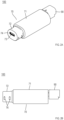
- FIG. 2A is a perspective view showing an example of a connector unit according to a present embodiment
- FIG. 2B is a side view thereof
- FIG. 3A is a rear view of the connector unit shown in FIG. 2A
- FIG. 3B is a cross-sectional view taken along a line C-C in FIG. 3A
- FIG. 4 is an exploded perspective view of the connector unit shown in FIG. 2A .
- potting resin 130 described later is not shown, and in FIG. 3B , electronic components 50 are not shown.
- a connector unit 100 is mainly formed from a printed wiring board 30, an interface connector 40, electronic components 50, a waterproof sealing member 60, a case 70, and a rear surface connector 90.
- the printed wiring board 30 is a single or multi-layer wiring board that is mainly composed of glass epoxy resin, for example.
- FIG. 5A is a perspective view showing a printed circuit board 35 of the connector unit shown in FIG. 2A
- FIG. 5B is a side view of the printed wiring board 30 shown in FIG. 5A .
- the printed wiring board 30 has a flat plate shape including an upper surface 30A and a lower surface 30B having a substantially rectangular shape, and includes an end part 32 including an end surface corresponding to one end in a lengthwise direction, and an end part 33 including an end surface on an opposite side from the end part 32.
- the printed wiring board 30 includes a first region 30a that extends from the end part 32 in a direction of the end part 33, and a second region 30b that is adjacent to the first region 30a and that extends to the end part 33.
- the first region 30a is a region of the printed wiring board 30 from the end part 32 to the boundary 30c
- the second region 30b is a region of the printed wiring board 30 from the boundary 30c to the end part 33.
- the interface connector 40, the electronic components 50, and the rear surface connector 90 are mounted on the upper surface 30A of the printed wiring board 30.
- the printed wiring board 30 where the interface connector 40, the electronic components 50, and the rear surface connector 90 are mounted will be referred to as "printed circuit board 35".
- the printed circuit board 35 is housed in the case 70.
- the interface connector 40 to be connected to a connector of a smartphone or the like is mounted on the upper surface 30A of the printed wiring board 30, on the end part 32 side of the first region 30a.
- a terminal 42 of the interface connector 40 is covered by a metal shell 41 have a non-watertight structure, and is positioned facing outside of the case 70 through an opening portion 73 provided in a front plate part 74 of the case 70.
- the interface connector 40 according to the present embodiment is a USB Type-C connector.
- the type of the interface connector 40 is not particularly limited as long as the interface connector is an interface connector having a non-watertight structure.
- interface connector 40 may be used.
- a USB Type-A connector or an HDMI (registered trademark) connector may be used.
- HDMI registered trademark
- the interface connector 40 has a non-watertight structure, even when the interface connector 40 receives water through the opening portion 73, the water is not retained inside the interface connector 40 as long as the water is in small quantity, and the water is discharged outside the interface connector.
- the electronic components 50 which are surface mount components such as an IC chip and a capacitor, are mounted on the upper surface 30A of the printed wiring board 30, on the second region 30b side.
- a plurality of electronic components 50 are mounted, as shown in FIG. 5A .
- the number of electronic components 50 on the printed wiring board 30 of the connector unit 100 according to the present embodiment is not limited to plural.
- the first region 30a side inside the case 70 is a non-waterproof region
- the second region 30b side is a waterproof region.
- the electronic components 50 according to the present embodiment may include an electronic component that requires high waterproofness than the interface connector 40. Additionally, in the case where the connector unit 100 of the present embodiment can be implemented without the electronic components 50, the electronic components 50 do not necessarily have to be mounted.
- FIG. 6A is a perspective view of the printed circuit board 35 where the waterproof sealing member 60 is integrally formed.
- FIG. 6B is a cross-sectional view seen from the interface connector 40 side, where the connector unit 100 is cut along a surface including the boundary 30c. In FIG. 6B , the printed wiring board 30 and the rear surface connector 90 on a backward side (a rear side) of the boundary 30c are not shown.
- the waterproof sealing member 60 formed on the printed wiring board 30 includes pressing surfaces 60A, 60B, 60C, and 60D that press an inner surface of a tubular part 72 when inserted inside the case 70.
- the pressing surface 60A and the pressing surface 60B, the pressing surface 60B and the pressing surface 60C, the pressing surface 60C and the pressing surface 60D, and the pressing surface 60D and the pressing surface 60A are continuous to each other, and a surface that is continuous as a whole is formed.
- the pressing surfaces 60A, 60B, 60C, and 60D press an inner periphery 72c that is an inner periphery of the tubular part 72 of the case 70 and that faces toward the outer periphery 30c1, and are thus in close contact with the inner surface of the tubular part 72.
- the second region 30b side of the inside of the case 70 according to the present embodiment is a waterproof region.
- the potting resin 130 is injected or the rear surface connector 90 is provided, and details will be given later.
- the waterproof sealing member 60 and making the second region 30b side inside the case 70 a waterproof region a waterproof function is achieved on the second region 30b side even when water enters from a rear end side of the case 70 (a side of the case 70 opposite from the front plate part 74), not to mention a case where water enters through the opening portion 73 of the case 70. Accordingly, the electronic components 50 and the printed wiring board 30 on the second region 30b side inside the case 70 are not affected by water regardless of which orientation the connector unit 100 is attached to another device of a vehicle or the like where the connector unit 100 is mounted.
- the waterproof sealing member 60 of the present embodiment is integrally formed with the printed wiring board 30 by insert molding, for example.
- the printed circuit board 35 is prepared in advance.
- the printed circuit board 35 is obtained by printing cream solder in the form of paste on component mount positions on the printed wiring board 30, placing the interface connector 40, the electronic components 50, and the rear surface connector 90 on the printed wiring board 30, and performing a soldering step by adding heat in a reflow furnace.
- the printed circuit board 35 is mounted in a mold for the waterproof sealing member 60 that is prepared in advance, the mold is closed and a hot melt material is injected after mold clamping, and insert molding is thereby performed.
- the waterproof sealing member 60 is thereby integrally formed on the printed wiring board 30 (the printed circuit board 35).
- a material for insert molding and a step of reflow process are desirably adjusted such that molding can be performed at a lower temperature (such as from 180°C to 200°C) than a temperature (also referred to as "application temperature") of the soldering step in the reflow furnace.
- thermoplastic resin having a low-melting point such as EVA, olefin, synthetic rubber, polyamide, or polyester.
- EVA ethylene glycol dimethacrylate
- olefin ethylene glycol dimethacrylate
- synthetic rubber such as polyamide
- polyamide such materials are not restrictive as long as the insert molding method described above can be implemented, and the inside of the case 70 can be separated into the first region 30a side and the second region 30b side from the standpoint of waterproofness.
- the waterproof sealing member 60 as one member is integrally formed with the printed circuit board 35.
- the waterproof sealing member 60 is not limited to be formed as one member, and a waterproof sealing member 61 formed from a plurality of non-annular members may also be used, as shown in FIGS. 7A and 7B , for example.
- FIG. 7A is an exploded perspective view of the waterproof sealing member 61, where the waterproof sealing member 61 is to be mounted on the printed circuit board 35.
- FIG. 7B is a cross-sectional view seen from the interface connector 40 side, where the connector unit 100 where the waterproof sealing member 61 is mounted is cut along the surface including the boundary 30c.
- the printed wiring board 30 and the rear surface connector 90 on the backward side (the rear side) of the boundary 30c are not shown.
- the waterproof sealing member 61 of a present modification is formed from a combination of two waterproof sealing members, i.e., a first waterproof sealing member 610 and a second waterproof sealing member 620.
- examples of a material of the waterproof sealing member 61 include thermoplastic resin having a low-melting point, such as EVA, olefin, synthetic rubber, polyamide, and polyester, but as in the case of the waterproof sealing member 60, these materials are not restrictive.
- the first waterproof sealing member 610 is formed from a pair of separating parts 611 and 612, and a coupling part 613 that couples the separating parts 611 and 612 into a substantially U-shape.
- the first waterproof sealing member 610 includes sandwiching surfaces 610a, 610b, and 610c for sandwiching the upper surface 30A and the lower surface 30B of the printed wiring board 30, and pressing surfaces 610A, 610B, and 610C for pressing the inner surface of the tubular part 72.
- FIG. 7A the first waterproof sealing member 610 includes sandwiching surfaces 610a, 610b, and 610c for sandwiching the upper surface 30A and the lower surface 30B of the printed wiring board 30, and pressing surfaces 610A, 610B, and 610C for pressing the inner surface of the tubular part 72.
- the second waterproof sealing member 620 is formed from a pair of separating parts 621 and 622, and a coupling part 623 that couples the separating parts 621 and 622 into a substantially U-shape.
- the second waterproof sealing member 620 includes sandwiching surfaces 620a, 620b, and 620c for sandwiching the upper surface 30A and the lower surface 30B of the printed wiring board 30, and pressing surfaces 620A, 620B, and 620C for pressing the inner surface of the tubular part 72.
- the first waterproof sealing member 610 and the second waterproof sealing member 620 have asymmetrical shapes, and form a substantially same shape as the waterproof sealing member 60 when combined together.
- the sandwiching surfaces 610a, 610b, and 610c of the first waterproof sealing member 610 and the sandwiching surfaces 620a, 620b, and 620c of the second waterproof sealing member 620 are brought into contact with and along the outer periphery 30c1 of the printed wiring board 30. Furthermore, an end part 611a of the first waterproof sealing member 610 and an end part 621a of the second waterproof sealing member 620, and an end part 611b of the first waterproof sealing member 610 and an end part 621b of the second waterproof sealing member 620 are brought into contact with each other while facing each other.
- an end part 612a of the first waterproof sealing member 610 and an end part 622a of the second waterproof sealing member 620, and an end part 612b of the first waterproof sealing member 610 and an end part 622b of the second waterproof sealing member 620 are brought into contact with each other while facing each other. Fixing is performed using an adhesive or the like so that such contact is maintained, or in other words, relative positions are not shifted, and the waterproof sealing member 61 is thereby disposed while being integrated with the printed circuit board 35. Sizes of the first waterproof sealing member 610 and the second waterproof sealing member 620 are such that the waterproof sealing member 61 as a whole has a substantially same size as the waterproof sealing member 60.
- the first waterproof sealing member 610 has a recessed shape and the second waterproof sealing member 620 has a protruding shape, but the shapes at the contact part are not limited to such shapes, and a more complex shape such as an interlocking structure may be adopted to achieve stronger joint than when joining by the waterproof sealing member 61 described above.
- the waterproof sealing member includes a plurality of members, as in the case of the waterproof sealing member 61, a mold for insert molding does not have to be created, and a waterproof sealing member that is integrated with the printed wiring board 30 (the printed circuit board 35) can be formed by a sole process of joining, by preparing a necessary number of waterproof sealing members 61 in advance.
- the printed circuit board 35 where the waterproof sealing member 60 is integrally formed, or the printed circuit board 35 where the waterproof sealing member 61 is integrally joined to the printed wiring board 30 is housed inside the case 70.
- the case 70 is a molded article formed from thermoplastic resin such as ABS.
- the case 70 includes tubular parts 71 and 72 having rectangular tube shapes, and the front plate part 74 positioned on a front end of the tubular part 72.
- the tubular part 71 has a tubular shape that is a size larger than the tubular part 72.
- the opening portion 73 that allows insertion/removal of a mating connector of the interface connector 40 is formed in the front plate part 74 of the tubular part 72.
- Two water discharge holes 76 are formed in the tubular part 72, or in other words, on the first region 30a side of the case 70, at lower parts on each of left and right sides across the front plate part 74.
- the opening portion 73 and the water discharge holes 76 each communicate with an inner space of the tubular part 72.
- the water discharge holes 76 are provided, even when water enters from the opening portion 73 side, the water is not kept retained on the first region 30a side inside the case 70, and is discharged outside the case 70 through the water discharge holes 76.
- the interface connector 40 has a non-watertight structure, water received by the interface connector 40 is discharged outside the interface connector 40. As a result, the water is temporarily retained on the first region 30a side inside the case 70; however, the water discharged from the interface connector 40 is also eventually discharged outside the case 70 through the water discharge holes 76. Accordingly, even if a great amount of water is received from the opening portion 73, the water is not kept retained on the first region 30a side inside the case 70. Accordingly, the terminal 42 of the interface connector 40 may not rust due to water regardless of which orientation the connector unit 100 is attached to another device of a vehicle or the like where the connector unit 100 is mounted.
- the printed circuit board 35 where the waterproof sealing member 60 is integrally formed, or the printed circuit board 35 where the waterproof sealing member 61 is joined to the printed wiring board 30 is pushed and inserted (inserted under pressure) from a rear end side of the tubular part 71 (opposite side of the case 70 from the front plate part 74), and is housed inside the case 70.
- sliders 71a, 71b, 71c, and 71d are formed on an inner surface of the tubular part 71, on side surface regions on both left and right sides.
- the inside of the case 70 is separated into the first region 30a side and the second region 30b side by the waterproof sealing member 60 (or the waterproof sealing member 61). That is, in the case where the waterproof sealing member 60 is used as the waterproof sealing member, the pressing surfaces 60A, 60B, 60C, and 60D of the waterproof sealing member 60 press the inner surface of the tubular part 72, as shown in FIG. 6B .
- the waterproof sealing member 60 thus separates the inside of the case 70 into the first region 30a side and the second region 30b side.
- the waterproof sealing member 61 is used as the waterproof sealing member, the pressing surfaces 610A, 610B, and 610C of the first waterproof sealing member 610, and the pressing surfaces 620A, 620B, and 620C of the second waterproof sealing member 620 press the inner surface of the tubular part 72, as shown in FIG. 7B .
- the waterproof sealing member 61 thus separates the inside of the case 70 into the first region 30a side and the second region 30b side.
- the rear surface connector 90 to be connected to a harness connector 400 described later is mounted on the upper surface 30A of the printed wiring board 30.
- the rear surface connector 90 includes a housing 91 and terminals 92.
- the housing 91 has a tubular shape, and is formed from the fitting part 91a to be fitted with the harness connector 400, and a base part 91b that covers a base end of the fitting part 91a.
- two terminal insertion holes 91c are formed in the base part 91b.
- the rear surface connector 90 according to the present embodiment includes two terminals 92.
- the terminal 92 has a shape that is bent in an L-shape, and a pair of protrusions 92a protruding in both sides in a width direction is formed on one side of the L-shape. As shown in FIGS. 3B and 4 , the terminal 92 is attached to the housing 91 by having the one side of the L-shape pushed into the terminal insertion hole 91c. The side of the terminal 92 that is pushed in is exposed inside the fitting part 91a so as to be able to be connected to the harness connector 400. The other side of the L-shape of the terminal 92 is inserted and soldered to a through hole 31a provided on the end part 33 side of the printed wiring board 30.
- the potting resin 130 is injected on the second region 30b side inside the case 70.
- a material of the potting resin 130 include, but are not limited to, urethane resin, epoxy resin, and silicone resin.
- the injected potting resin 130 is indicated using a reference numeral, and is shown with no patterns without using diagonal lines or the like so that the potting resin 130 is distinguishable from the tubular part 71 and the printed wiring board 30.
- injection of the potting resin 130 is performed until the second region 30b side inside the case 70 is filled with the potting resin 130. Due to being filled with the potting resin 130, the inside of the case 70 may be such that the first region 30a side is a non-waterproof region, and the second region 30b side is a waterproof region.
- Waterproofness may be achieved by placing the second region 30b side inside the case 70 in a hollow state without injecting the potting resin 130, and by providing a rear surface cover 80 on the tubular part 71.
- FIG. 8A is a rear view showing an example of the connector unit, where the rear surface cover 80 is included, and FIG. 8B is a cross-sectional view taken along a line C-C in FIG. 8A .
- the second region 30b side inside the case 70 is not filled with the potting resin 130.
- a rear end of the tubular part 71 of the case 70, or in other words, an end part of the case 70 on the second region 30b side is covered by the rear surface cover 80.
- the rear surface cover 80 includes a circular flat plate having a same shape as an inner diameter of the tubular part 71.
- a contact part between the rear surface cover 80 and the case 70 or in other words, a part between an inner peripheral surface of a rear end of the tubular part 71 and an outer peripheral surface of the rear surface cover 80, is tightly bonded by an adhesive or the like.
- a waterproof function is achieved on the second region 30b side inside the case 70.
- the rear surface cover 80 may be integrally formed between the fitting part 91a and the base part 91b.
- the base part 91b is thereby made a part of the rear surface cover 80, and the fitting part 91a is made to protrude rearward from the rear surface cover 80.
- the rear surface cover 80 may instead be formed as a separate body from the rear surface connector 90.
- the rear surface cover 80 may be formed as a structure that holds the rear surface connector 90. It is conceivable to form the rear surface cover 80 from, but not limited to, a homogeneous material as the waterproof sealing member 60.
- An annular groove may be formed on an outer peripheral surface of the rear surface cover 80, and a rubber seal having an annular shape may be attached to the annular groove, and the rubber seal may be sandwiched between the inner peripheral surface of the rear end of the tubular part 71 and the outer peripheral surface of the rear surface cover 80.
- the waterproof function on the second region 30b side inside the case 70 may thereby be even better complemented.
- the second region 30b side inside the case 70 may be filled with the potting resin 130 to further increase the waterproof function. Additionally, in the case where the potting resin 130 is not injected, a moisture prevention coat may be applied on the printed wiring board 30 from the standpoint of waterproofness even when the rear surface cover 80 is provided.
- a coating agent a normal-temperature type fluorine coating agent may be used, or a coating agent that uses urethane-, acrylic-, or silicone-based resin as a film component may be used, for example.
- the rear surface cover 80 may achieve a waterproof function on the second region 30b side inside the case 70, and also, the rear surface cover 80 may achieve the waterproof function at a lower cost than the potting resin 130.
- the waterproof sealing member (the waterproof sealing member 60, the waterproof sealing member 61) of the connector unit 100 according to the present embodiment separates the inside of the case 70 into the first region 30a side and the second region 30b side. Furthermore, the second region 30b side inside the case 70 is a waterproof region.
- the interface connector 40 is housed on the first region 30a side inside the case 70 that is a non-waterproof region, but the interface connector 40 according to the present embodiment has a non-watertight structure. Accordingly, even when the connector unit 100 is attached to another device of a vehicle or the like with the opening portion 73 facing upward and water is allowed to enter, or in other words, even when water is retained in a space on the first region 30a side inside the case 70 due to the interface connector 40 being used while facing upward, water is not kept retained in the interface connector 40 as long as the water is in small quantity, and the water is discharged outside the interface connector 40. Accordingly, the terminal 42 of the interface connector 40 is prevented from rusting due to water.
- the second region 30b side inside the case 70 is a waterproof region, and a waterproof function is achieved.
- the connector unit 100 even when water enters from the opening portion 73 side of the case 70, the water does not enter the second region 30b side inside the case thanks to the waterproof sealing member 60. Even if water passes through the waterproof sealing member 60, the second region 30b side is a waterproof region, and the water does not enter the second region 30b side inside the case. Even if water enters from a rear end side of the case 70, the second region 30b side inside the case 70 is a waterproof region, and the water does not enter the second region 30b side inside the case 70. Accordingly, the printed wiring board 30 and the electronic components 50 housed on the second region 30b side inside the case 70 are not affected by water regardless of which orientation the connector unit 100 is attached to another device of a vehicle or the like where the connector unit 100 is mounted.
- the connector unit 100 of the present embodiment may relax a constraint on the attitude at the time of use, but the connector unit of the present invention is not limited to the embodiment described above.
- a pigtail connector unit according to which a cable is directly connected to the printed wiring board 30 instead of the rear surface connector 90 and is drawn out may be adopted.
- a connector unit that does not include external connections other than the interface connector 40 may be adopted.
- FIG. 9A is a diagram showing an example of attachment of the connector unit 100 to another device of a vehicle or the like, FIG. 9A showing a state where the connector unit 100 is attached to a handlebar of a motorcycle using a holding tool.
- FIG. 9B is a side view of FIG. 9A
- FIG. 9C is a rear view of FIG. 9A, FIG. 9C showing a part of a case holding part 210 and the harness connector 400.
- a vehicle-mounted connector device 500 according to the present embodiment includes the connector unit 100 and a holding tool 200. As shown in FIGS.
- the vehicle-mounted connector device 500 is a device for attaching the connector unit 100 to a handlebar 300 of a motorcycle via the holding tool 200.
- the connector unit 100 indicated by a dotted line in FIG. 9B is attached with the opening portion 73 facing a driver's seat and being horizontal relative to the rear surface connector 90 (i.e., parallel to the ground).
- the handlebar 300 extends horizontally and sideways relative to a driver when the driver is seated on the driver's seat (not shown). Although not shown in FIGS. 9A and 9B , the handlebar 300 is integrated with a main body of the motorcycle via another support member or the like.
- Main structural elements of the holding tool 200 are the case holding part 210 and a handlebar holding part 220.
- the case holding part 210 is for holding an outer periphery of the case 70 of the connector unit 100.
- the case holding part 210 includes a pair of a first holding part 211 and a second holding part 212 that form a box shape when seen from outside, a cap 216, and a holding base 215.
- the first holding part 211 as a cover and the second holding part 212 as a base are fitted with each other so that an outer shape of the case holding part 210 is a box shape. Furthermore, an inner shape of the 210 is such that the entire connector unit 100 having a cylindrical shape is housed while being in close contact with the inner shape of the case holding part 210.
- a front surface 211a of the first holding part 211 and a front surface 212a of the second holding part 212 form a front surface 210a of the case holding part 210, and an opening portion 213 is formed in the front surface 210a, the opening portion 213 facing the interface connector 40 and the opening portion 73 of the connector unit 100 and allowing insertion/removal of a connector of an electronic device such as a smartphone into/from the interface connector 40.
- an electronic device such as a smartphone
- a rear surface 211b of the first holding part 211 and a rear surface 212b of the second holding part 212 form a rear surface 210b of the case holding part 210
- an opening portion 214 that allows insertion of a cable part of the harness connector 400 connected to the rear surface connector 90 of the connector unit 100 is formed in the rear surface 210b.
- a water discharge hole may be provided in a side surface or a bottom surface of the second holding part 212 such that water discharged from the water discharge hole 76 in the connector unit 100 may be discharged.
- the cap 216 is turnably supported on the first holding part 211 of the case holding part 210.
- the cap 216 includes a lid part 216a for covering the opening portion 213 in the front surface 210a, and a pair of arm parts 216b and 216c that are integrally formed with the lid part 216a, the pair of arm parts 216b and 216c being on a rear side of the lid part 216a in a state closed state.
- a protruding part, not shown, that protrudes inward is provided on an end part of each arm part 216b, 216c, and each protruding part and a side surface of the first holding part 211 are turnably supported.
- the opening portion 213 may be covered by using the lid part 216a when the connector unit 100 is not used. Furthermore, at the time of use of the connector unit 100, or in other words, at a time of connecting a connector of an electronic device to the interface connector 40 from the driver's seat side, the lid part 216a is lifted so that the interface connector 40 faces outside, and the connector can be connected.
- a turning direction of the cap 216 is indicated by an arrow, and the cap 216 in a closed state is indicated by a dash-dotted line.
- the holding base 215 is integrally formed on a bottom surface of the second holding part 212 of the case holding part 210.
- the holding base 215 serves to fix the case holding part 210 on the handlebar holding part 220.
- the handlebar holding part 220 is for holding the handlebar 300 of the motorcycle.
- the handlebar holding part 220 includes a base part 221, a belt 222, and a fixing part 223.
- the base part 221 serves to fix the case holding part 210 and the handlebar holding part 220 to each other. That is, the base part 221 of the handlebar holding part 220 and the holding base 215 of the case holding part 210 are integrally coupled by being tightly fixed to each other by an adhesive or the like, for example.
- the base part 221 and the holding base 215 are completely fixed to each other so as not to allow relative movement, but instead, a turning mechanism part for turnably supporting the base part 221 and the holding base 215 may be provided between the two.
- the connector unit 100 mounted on the handlebar 300 via the holding tool 200 may be set to face a desired direction by using the turning mechanism part.
- the belt 222 formed from an elastic member is integrally formed with the base part 221 in a manner capable of grasping an outer periphery of the handlebar 300 in a wrapping manner.
- the belt 222 has a length that allows the belt 222 to grasp the outer periphery of the handlebar 300 having a circular cross-section in a wrapping manner, and fastening strength of the belt 222 around the handlebar 300 is adjusted using the fixing part 223.
- the handlebar holding part 220 holds the handlebar 300 of the motorcycle due to the fastening strength being adjusted.
- the configuration of the vehicle-mounted connector device 500 is as described above, and a method of attaching the connector unit 100 to the handlebar 300 of the motorcycle using the holding tool 200 is as described below.
- the handlebar 300 is held by the handlebar holding part 220 (step S1). More specifically, as shown in FIG. 9B , the handlebar 300 having a circular cross-section is circumferentially grasped using the belt 222, and the fastening strength of the belt 222 around the handlebar 300 is adjusted using the fixing part 223.
- an attachment angle of the belt 222 is adjusted using the fixing part 223 so that the opening portion 213 of the case holding part 210 integrally formed with the handlebar holding part 220 faces a direction desired by the driver. Accordingly, attachment to the handlebar 300 may be such that the opening portion 73 of the connector unit 100 faces upward, for example.
- step S2 the connector unit 100 is held by the case holding part 210 (step S2). More specifically, engagement of the first holding part 211 and the second holding part 212 is released and the first holding part 211 as a cover is opened, and the connector unit 100 is mounted inside the second holding part 212. At this time, the connector unit 100 is mounted in the second holding part 212 in such a way that the opening portion 73 of the connector unit 100 faces the opening portion 213 of the case holding part 210, and the cable part of the harness connector 400 mounted on the rear surface connector 90 of the connector unit 100 is inserted through the opening portion 214 of the case holding part 210.
- the connector unit 100 After the connector unit 100 is mounted in the second holding part 212, the first holding part 211 is closed and the first holding part 211 and the second holding part 212 are fitted together, and the connector unit 100 is housed in the case holding part 210. Additionally, in the case of the holding tool 200 provided with the turning mechanism part described above, the connector unit 100 may be adjusted to face a desired direction by using a turning support function of the turning mechanism part after step S2. Accordingly, attachment to the handlebar 300 may be such that the opening portion 73 of the connector unit 100 faces upward, for example.
- the vehicle-mounted connector device 500 includes the connector unit 100, and thus, an effect that same as that of the connector unit 100 described above may be obtained. Furthermore, because the vehicle-mounted connector device 500 includes the holding tool 200, attachment to a vehicle such as a motorcycle may be in such a way that the connector unit 100 faces a direction desired by a user. More particularly, in the case where the connector unit 100 of the present embodiment is used as the vehicle-mounted connector device 500 including the holding tool to be attached to the handlebar of a motorcycle, a degree of freedom can be ensured with respect to an angle of attachment to the handlebar, and attachment at an attitude where the opening portion 73 faces upward is enabled.
- a method of attachment of the vehicle-mounted connector device 500 to a vehicle is not limited to the method described above, and for example, the order of step S1 and step S2 may be changed or step S1 and step S2 may be performed in parallel.
- the connector unit 100 and the vehicle-mounted connector device 500 described in the present embodiment may, of course, be changed as appropriate within the scope of the gist of the present invention.
Landscapes
- Engineering & Computer Science (AREA)
- Microelectronics & Electronic Packaging (AREA)
- Mechanical Engineering (AREA)
- Connector Housings Or Holding Contact Members (AREA)
Abstract
Description
- The present invention relates to a connector unit that can be used by being attached to another device of a vehicle or the like.
- Some prior art waterproof connectors reliably prevent water or the like from seeping through a gap between components forming the connector due to capillary action (for example, see Patent literature 1).
FIGS. 1A and 1B are diagrams for describing the waterproof connector of the prior art. As shown inFIGS. 1A and 1B , the waterproof connector includes highlyconductive contacts 2, a metal shell 3 formed from a metal tube body inside which the contacts are disposed, an electrically insulating housing 4 where thecontacts 2 are fixed, and an externalwaterproof sealing member 8 formed from annular sealing packing having an opening that is large enough to be attached to an outer periphery of the housing 4, where the housing 4 allows thecontacts 2 to be disposed inside the metal shell 3 while being separated from an inner wall to be in an electrically insulated state, the housing 4 being formed from resin moldedarticles 4a to 4e and 4e1 that are integrally molded by injection of electrically insulating synthetic resin. - Patent literature 1:
Japanese Patent Application Laid-Open No. 2012-59540 - However, when a
waterproof connector 1 ofPatent literature 1 is mounted on a device with a front opening 3F facing upward, a connector removal side of thewaterproof connector 1 is kept facing upward while being used. Thewaterproof connector 1 does not include a water discharge structure, and when water enters the housing 4 for some reasons, the water is retained inside the housing 4. Even a small amount of water, if retained for an extended time, may rust front end parts of a plurality ofcontacts 2 of thewaterproof connector 1 that are exposed inside the housing 4. The problem with thewaterproof connector 1 ofPatent literature 1 has been that there is a constraint on attitude at the time of mounting on a device because it has to be mounted on a device with the front opening 3F facing downward, for example, so that thewaterproof connector 1 is not used with the connector removal side facing upward. - In view of the problem described above, an object of the present invention is to provide a connector unit with which a constraint on an attitude at the time of use can be relaxed.
- To solve the problem described above, a connector unit according to a present embodiment comprises a printed wiring board, an interface connector, a waterproof sealing member, and a case. The printed wiring board having a flat plate shape includes a first region and a second region that is adjacent to the first region. The interface connector is mounted on the first region of the printed wiring board, and includes a shell having a non-watertight structure. The waterproof sealing member covers a boundary between the first region and the second region of the printed wiring board. The case includes an opening portion for allowing insertion/removal of a mating connector of the interface connector, and houses the printed wiring board, the interface connector, and the waterproof sealing member. The waterproof sealing member is formed so as to cover an outer periphery of the boundary of the printed wiring board and an inner periphery of the case facing toward the outer periphery of the boundary in a close contact manner, and separate inside of the case into the first region side and the second region side across the waterproof sealing member. The second region side inside the case is a waterproof region.
- According to the present embodiment, the interface connector having a non-watertight structure is mounted on the first region side inside the case. Accordingly, even when the opening portion faces upward in an attached state and water is retained in the first region, the water is not kept retained inside the interface connector as long as the water is in small quantity, and the water is discharged outside the interface connector. The second region side inside the case is a waterproof region, and a waterproof function is achieved. Accordingly, the connector unit of the present embodiment can relax a constraint on an attitude at the time of use. More particularly, in the case where the connector unit of the present embodiment is used as a vehicle-mounted connector device including a holding tool to be attached to a handlebar of a motorcycle, a degree of freedom can be ensured with respect to an angle of attachment to the handlebar, and attachment at an attitude where the opening portion faces upward is enabled.
-
- [
FIG. 1A] FIG. 1A is a diagram for describing a waterproof connector of a prior art; - [
FIG. 1B] FIG. 1B is a diagram for describing the waterproof connector of the prior art; - [
FIG. 2A] FIG. 2A is a perspective view showing an example of a connector unit according to a present embodiment; - [
FIG. 2B] FIG. 2B is a side view of the connector unit shown inFIG. 2A ; - [
FIG. 3A] FIG. 3A is a rear view of the connector unit shown inFIG. 2A ; - [
FIG. 3B] FIG. 3B is a cross-sectional view taken along a line C-C inFIG. 3A ; - [
FIG. 4] FIG. 4 is an exploded perspective view of the connector unit shown inFIG. 2A ; - [
FIG. 5A] FIG. 5A is a perspective view showing a printedcircuit board 35 of the connector unit shown inFIG. 2A ; - [
FIG. 5B] FIG. 5B is a side view of a printedwiring board 30 shown inFIG. 5A ; - [
FIG. 6A] FIG. 6A is a perspective view of the printedcircuit board 35 where awaterproof sealing member 60 is integrally formed; - [
FIG. 6B] FIG. 6B is a cross-sectional view seen from aninterface connector 40 side, where aconnector unit 100 is cut along a surface including aboundary 30c; - [
FIG. 7A] FIG. 7A is an exploded perspective view of awaterproof sealing member 61, where thewaterproof sealing member 61 is to be mounted on the printedcircuit board 35; - [
FIG. 7B] FIG. 7B is a cross-sectional view seen from theinterface connector 40 side, where theconnector unit 100 where thewaterproof sealing member 61 is mounted is cut along the surface including theboundary 30c; - [
FIG. 8A] FIG. 8A is a rear view showing an example of the connector unit, where arear surface cover 80 is included; - [
FIG. 8B] FIG. 8B is a cross-sectional view taken along a line C-C inFIG. 8A ; - [
FIG. 9A] FIG. 9A is a diagram showing an example of attachment of theconnector unit 100 to another device of a vehicle or the like,FIG. 9A showing a state where theconnector unit 100 is attached to a handlebar of a motorcycle using a holding tool; - [
FIG. 9B] FIG. 9B is a side view ofFIG. 9A ; and - [
FIG. 9C] FIG. 9C is a rear view ofFIG. 9A, FIG. 9C showing a part of acase holding part 210 and aharness connector 400. - Hereinafter, an embodiment of the present invention will be described with reference to the drawings. Additionally, in the following description, structural parts having a same function are denoted by a same number, and a redundant description will be omitted.
-
FIG. 2A is a perspective view showing an example of a connector unit according to a present embodiment, andFIG. 2B is a side view thereof.FIG. 3A is a rear view of the connector unit shown inFIG. 2A , andFIG. 3B is a cross-sectional view taken along a line C-C inFIG. 3A .FIG. 4 is an exploded perspective view of the connector unit shown inFIG. 2A . InFIG. 3A , pottingresin 130 described later is not shown, and inFIG. 3B ,electronic components 50 are not shown. - As shown in
FIG. 4 , aconnector unit 100 according to the present embodiment is mainly formed from a printedwiring board 30, aninterface connector 40,electronic components 50, awaterproof sealing member 60, acase 70, and arear surface connector 90. - The printed
wiring board 30 is a single or multi-layer wiring board that is mainly composed of glass epoxy resin, for example.FIG. 5A is a perspective view showing a printedcircuit board 35 of the connector unit shown inFIG. 2A , andFIG. 5B is a side view of the printedwiring board 30 shown inFIG. 5A . - As shown in
FIGS. 5A and 5B , the printedwiring board 30 according to the present embodiment has a flat plate shape including anupper surface 30A and alower surface 30B having a substantially rectangular shape, and includes anend part 32 including an end surface corresponding to one end in a lengthwise direction, and anend part 33 including an end surface on an opposite side from theend part 32. The printedwiring board 30 includes afirst region 30a that extends from theend part 32 in a direction of theend part 33, and asecond region 30b that is adjacent to thefirst region 30a and that extends to theend part 33. When a surface at a boundary between thefirst region 30a and thesecond region 30b is defined as aboundary 30c, thefirst region 30a is a region of the printedwiring board 30 from theend part 32 to theboundary 30c, and thesecond region 30b is a region of the printedwiring board 30 from theboundary 30c to theend part 33. - The
interface connector 40, theelectronic components 50, and therear surface connector 90 are mounted on theupper surface 30A of the printedwiring board 30. In the present embodiment, the printedwiring board 30 where theinterface connector 40, theelectronic components 50, and therear surface connector 90 are mounted will be referred to as "printedcircuit board 35". As shown inFIGS. 3A and 3B , the printedcircuit board 35 is housed in thecase 70. - The
interface connector 40 to be connected to a connector of a smartphone or the like is mounted on theupper surface 30A of the printedwiring board 30, on theend part 32 side of thefirst region 30a. As shown inFIGS. 3B to 5A , aterminal 42 of theinterface connector 40 is covered by ametal shell 41 have a non-watertight structure, and is positioned facing outside of thecase 70 through an openingportion 73 provided in afront plate part 74 of thecase 70. Theinterface connector 40 according to the present embodiment is a USB Type-C connector. However, the type of theinterface connector 40 is not particularly limited as long as the interface connector is an interface connector having a non-watertight structure. For example, other interface connectors such as a USB Type-A connector or an HDMI (registered trademark) connector may be used. Because theinterface connector 40 has a non-watertight structure, even when theinterface connector 40 receives water through the openingportion 73, the water is not retained inside theinterface connector 40 as long as the water is in small quantity, and the water is discharged outside the interface connector. - The
electronic components 50, which are surface mount components such as an IC chip and a capacitor, are mounted on theupper surface 30A of the printedwiring board 30, on thesecond region 30b side. With respect to theelectronic components 50 according to the present embodiment, a plurality ofelectronic components 50 are mounted, as shown inFIG. 5A . However, the number ofelectronic components 50 on the printedwiring board 30 of theconnector unit 100 according to the present embodiment is not limited to plural. Moreover, as described later, in the present embodiment, thefirst region 30a side inside thecase 70 is a non-waterproof region, and thesecond region 30b side is a waterproof region. Accordingly, theelectronic components 50 according to the present embodiment may include an electronic component that requires high waterproofness than theinterface connector 40. Additionally, in the case where theconnector unit 100 of the present embodiment can be implemented without theelectronic components 50, theelectronic components 50 do not necessarily have to be mounted. - A
waterproof sealing member 60 formed from a hot melt material is formed on an outer periphery 30c1 of theboundary 30c of the printedwiring board 30.FIG. 6A is a perspective view of the printedcircuit board 35 where thewaterproof sealing member 60 is integrally formed.FIG. 6B is a cross-sectional view seen from theinterface connector 40 side, where theconnector unit 100 is cut along a surface including theboundary 30c. InFIG. 6B , the printedwiring board 30 and therear surface connector 90 on a backward side (a rear side) of theboundary 30c are not shown. - An external
waterproof sealing member 8 as shown inFIGS. 1A and 1B that is formed from annular sealing packing cannot be mounted on the printedwiring board 30 having a flat plate shape, but as shown inFIGS. 6A and 6B , thewaterproof sealing member 60 of the present embodiment is integrally formed with the printedwiring board 30 by tightly contacting the printedwiring board 30 while extending along and covering the outer periphery 30c1 of theboundary 30c of the printedwiring board 30. As shown inFIG. 6B , thewaterproof sealing member 60 formed on the printedwiring board 30 includespressing surfaces tubular part 72 when inserted inside thecase 70. Thepressing surface 60A and thepressing surface 60B, thepressing surface 60B and thepressing surface 60C, thepressing surface 60C and thepressing surface 60D, and thepressing surface 60D and thepressing surface 60A are continuous to each other, and a surface that is continuous as a whole is formed. Thepressing surfaces inner periphery 72c that is an inner periphery of thetubular part 72 of thecase 70 and that faces toward the outer periphery 30c1, and are thus in close contact with the inner surface of thetubular part 72. When thewaterproof sealing member 60 is formed in the above manner, thewaterproof sealing member 60 separates inside of thecase 70 into thefirst region 30a side and thesecond region 30b side. - Furthermore, the
second region 30b side of the inside of thecase 70 according to the present embodiment is a waterproof region. For example, to achieve the waterproof region, thepotting resin 130 is injected or therear surface connector 90 is provided, and details will be given later. - By providing the
waterproof sealing member 60 and making thesecond region 30b side inside the case 70 a waterproof region, a waterproof function is achieved on thesecond region 30b side even when water enters from a rear end side of the case 70 (a side of thecase 70 opposite from the front plate part 74), not to mention a case where water enters through the openingportion 73 of thecase 70. Accordingly, theelectronic components 50 and the printedwiring board 30 on thesecond region 30b side inside thecase 70 are not affected by water regardless of which orientation theconnector unit 100 is attached to another device of a vehicle or the like where theconnector unit 100 is mounted. - The
waterproof sealing member 60 of the present embodiment is integrally formed with the printedwiring board 30 by insert molding, for example. At the time of forming thewaterproof sealing member 60, the printedcircuit board 35 is prepared in advance. The printedcircuit board 35 is obtained by printing cream solder in the form of paste on component mount positions on the printedwiring board 30, placing theinterface connector 40, theelectronic components 50, and therear surface connector 90 on the printedwiring board 30, and performing a soldering step by adding heat in a reflow furnace. - After the printed
circuit board 35 is prepared, the printedcircuit board 35 is mounted in a mold for thewaterproof sealing member 60 that is prepared in advance, the mold is closed and a hot melt material is injected after mold clamping, and insert molding is thereby performed. Thewaterproof sealing member 60 is thereby integrally formed on the printed wiring board 30 (the printed circuit board 35). In relation to a temperature at the time of insert molding, a material for insert molding and a step of reflow process are desirably adjusted such that molding can be performed at a lower temperature (such as from 180°C to 200°C) than a temperature (also referred to as "application temperature") of the soldering step in the reflow furnace. As a main component of the hot melt material, thermoplastic resin having a low-melting point, such as EVA, olefin, synthetic rubber, polyamide, or polyester, may be cited. However, such materials are not restrictive as long as the insert molding method described above can be implemented, and the inside of thecase 70 can be separated into thefirst region 30a side and thesecond region 30b side from the standpoint of waterproofness. - By obtaining the
waterproof sealing member 60 by insert molding, joining strength and durability can be increased, and the number of assembly steps can be reduced, and a positioning accuracy can be increased, for example. - A method is adopted above where the
waterproof sealing member 60 as one member is integrally formed with the printedcircuit board 35. However, thewaterproof sealing member 60 is not limited to be formed as one member, and awaterproof sealing member 61 formed from a plurality of non-annular members may also be used, as shown inFIGS. 7A and 7B , for example. -
FIG. 7A is an exploded perspective view of thewaterproof sealing member 61, where thewaterproof sealing member 61 is to be mounted on the printedcircuit board 35.FIG. 7B is a cross-sectional view seen from theinterface connector 40 side, where theconnector unit 100 where thewaterproof sealing member 61 is mounted is cut along the surface including theboundary 30c. InFIG. 7B , the printedwiring board 30 and therear surface connector 90 on the backward side (the rear side) of theboundary 30c are not shown. As shown inFIG. 7A , thewaterproof sealing member 61 of a present modification is formed from a combination of two waterproof sealing members, i.e., a firstwaterproof sealing member 610 and a second waterproof sealingmember 620. As in the case of thewaterproof sealing member 60, examples of a material of thewaterproof sealing member 61 include thermoplastic resin having a low-melting point, such as EVA, olefin, synthetic rubber, polyamide, and polyester, but as in the case of thewaterproof sealing member 60, these materials are not restrictive. - As shown in
FIG. 7A , the firstwaterproof sealing member 610 is formed from a pair of separatingparts coupling part 613 that couples the separatingparts FIG. 7B , the firstwaterproof sealing member 610 includes sandwichingsurfaces upper surface 30A and thelower surface 30B of the printedwiring board 30, andpressing surfaces tubular part 72. As shown inFIG. 7A , the second waterproof sealingmember 620 is formed from a pair of separatingparts coupling part 623 that couples the separatingparts FIG. 7B , the second waterproof sealingmember 620 includes sandwichingsurfaces upper surface 30A and thelower surface 30B of the printedwiring board 30, andpressing surfaces tubular part 72. As shown inFIGS. 7A and 7B , the firstwaterproof sealing member 610 and the second waterproof sealingmember 620 have asymmetrical shapes, and form a substantially same shape as thewaterproof sealing member 60 when combined together. - When mounting the
waterproof sealing member 61 on the printedcircuit board 35, the sandwichingsurfaces waterproof sealing member 610 and the sandwichingsurfaces member 620 are brought into contact with and along the outer periphery 30c1 of the printedwiring board 30. Furthermore, anend part 611a of the firstwaterproof sealing member 610 and anend part 621a of the second waterproof sealingmember 620, and anend part 611b of the firstwaterproof sealing member 610 and anend part 621b of the second waterproof sealingmember 620 are brought into contact with each other while facing each other. In the same manner, anend part 612a of the firstwaterproof sealing member 610 and anend part 622a of the second waterproof sealingmember 620, and anend part 612b of the firstwaterproof sealing member 610 and anend part 622b of the second waterproof sealingmember 620 are brought into contact with each other while facing each other. Fixing is performed using an adhesive or the like so that such contact is maintained, or in other words, relative positions are not shifted, and thewaterproof sealing member 61 is thereby disposed while being integrated with the printedcircuit board 35. Sizes of the firstwaterproof sealing member 610 and the second waterproof sealingmember 620 are such that thewaterproof sealing member 61 as a whole has a substantially same size as thewaterproof sealing member 60. Additionally, with respect to shapes at the contact part between the firstwaterproof sealing member 610 and the second waterproof sealingmember 620 of thewaterproof sealing member 61 of the present modification, the firstwaterproof sealing member 610 has a recessed shape and the second waterproof sealingmember 620 has a protruding shape, but the shapes at the contact part are not limited to such shapes, and a more complex shape such as an interlocking structure may be adopted to achieve stronger joint than when joining by thewaterproof sealing member 61 described above. - In the case where the waterproof sealing member includes a plurality of members, as in the case of the
waterproof sealing member 61, a mold for insert molding does not have to be created, and a waterproof sealing member that is integrated with the printed wiring board 30 (the printed circuit board 35) can be formed by a sole process of joining, by preparing a necessary number ofwaterproof sealing members 61 in advance. - The printed
circuit board 35 where thewaterproof sealing member 60 is integrally formed, or the printedcircuit board 35 where thewaterproof sealing member 61 is integrally joined to the printedwiring board 30 is housed inside thecase 70. For example, thecase 70 is a molded article formed from thermoplastic resin such as ABS. - As shown in
FIGS. 2A to 4 , thecase 70 includestubular parts front plate part 74 positioned on a front end of thetubular part 72. Thetubular part 71 has a tubular shape that is a size larger than thetubular part 72. The openingportion 73 that allows insertion/removal of a mating connector of theinterface connector 40 is formed in thefront plate part 74 of thetubular part 72. Two water discharge holes 76 are formed in thetubular part 72, or in other words, on thefirst region 30a side of thecase 70, at lower parts on each of left and right sides across thefront plate part 74. The openingportion 73 and the water discharge holes 76 each communicate with an inner space of thetubular part 72. Because the water discharge holes 76 are provided, even when water enters from the openingportion 73 side, the water is not kept retained on thefirst region 30a side inside thecase 70, and is discharged outside thecase 70 through the water discharge holes 76. As described above, because theinterface connector 40 has a non-watertight structure, water received by theinterface connector 40 is discharged outside theinterface connector 40. As a result, the water is temporarily retained on thefirst region 30a side inside thecase 70; however, the water discharged from theinterface connector 40 is also eventually discharged outside thecase 70 through the water discharge holes 76. Accordingly, even if a great amount of water is received from the openingportion 73, the water is not kept retained on thefirst region 30a side inside thecase 70. Accordingly, theterminal 42 of theinterface connector 40 may not rust due to water regardless of which orientation theconnector unit 100 is attached to another device of a vehicle or the like where theconnector unit 100 is mounted. - The printed
circuit board 35 where thewaterproof sealing member 60 is integrally formed, or the printedcircuit board 35 where thewaterproof sealing member 61 is joined to the printedwiring board 30 is pushed and inserted (inserted under pressure) from a rear end side of the tubular part 71 (opposite side of thecase 70 from the front plate part 74), and is housed inside thecase 70. As shown inFIG. 3A ,sliders tubular part 71, on side surface regions on both left and right sides. When performing push-in insertion of the printedcircuit board 35 where the waterproof sealing member 60 (or the waterproof sealing member 61) is integrally formed into thecase 70, an end part of the printedwiring board 30 in a width direction is inserted between thesliders sliders FIG. 3B , theinterface connector 40, the electronic component 50s, and the waterproof sealing member 60 (or the waterproof sealing member 61) on the printedwiring board 30, and therear surface connector 90 excluding afitting part 91a are housed inside thecase 70 together with the printedwiring board 30, at predetermined positions and at predetermined heights. - The inside of the
case 70 is separated into thefirst region 30a side and thesecond region 30b side by the waterproof sealing member 60 (or the waterproof sealing member 61). That is, in the case where thewaterproof sealing member 60 is used as the waterproof sealing member, thepressing surfaces waterproof sealing member 60 press the inner surface of thetubular part 72, as shown inFIG. 6B . Thewaterproof sealing member 60 thus separates the inside of thecase 70 into thefirst region 30a side and thesecond region 30b side. Furthermore, in the case where thewaterproof sealing member 61 is used as the waterproof sealing member, thepressing surfaces waterproof sealing member 610, and thepressing surfaces member 620 press the inner surface of thetubular part 72, as shown inFIG. 7B . Thewaterproof sealing member 61 thus separates the inside of thecase 70 into thefirst region 30a side and thesecond region 30b side. - On the
end part 33 side of thesecond region 30b, therear surface connector 90 to be connected to aharness connector 400 described later is mounted on theupper surface 30A of the printedwiring board 30. As shown inFIG. 4 , therear surface connector 90 includes ahousing 91 andterminals 92. Thehousing 91 has a tubular shape, and is formed from thefitting part 91a to be fitted with theharness connector 400, and abase part 91b that covers a base end of thefitting part 91a. As shown inFIG. 3A , twoterminal insertion holes 91c are formed in thebase part 91b. Therear surface connector 90 according to the present embodiment includes twoterminals 92. The terminal 92 has a shape that is bent in an L-shape, and a pair ofprotrusions 92a protruding in both sides in a width direction is formed on one side of the L-shape. As shown inFIGS. 3B and4 , the terminal 92 is attached to thehousing 91 by having the one side of the L-shape pushed into theterminal insertion hole 91c. The side of the terminal 92 that is pushed in is exposed inside thefitting part 91a so as to be able to be connected to theharness connector 400. The other side of the L-shape of the terminal 92 is inserted and soldered to a throughhole 31a provided on theend part 33 side of the printedwiring board 30. - After the waterproof sealing member 60 (or the waterproof sealing member 61) and the printed
circuit board 35 are housed inside thecase 70, thepotting resin 130 is injected on thesecond region 30b side inside thecase 70. Examples of a material of thepotting resin 130 include, but are not limited to, urethane resin, epoxy resin, and silicone resin. InFIG. 3B , the injectedpotting resin 130 is indicated using a reference numeral, and is shown with no patterns without using diagonal lines or the like so that thepotting resin 130 is distinguishable from thetubular part 71 and the printedwiring board 30. As shown inFIG. 3B , injection of thepotting resin 130 is performed until thesecond region 30b side inside thecase 70 is filled with thepotting resin 130. Due to being filled with thepotting resin 130, the inside of thecase 70 may be such that thefirst region 30a side is a non-waterproof region, and thesecond region 30b side is a waterproof region. - Waterproofness may be achieved by placing the
second region 30b side inside thecase 70 in a hollow state without injecting thepotting resin 130, and by providing a rear surface cover 80 on thetubular part 71. -
FIG. 8A is a rear view showing an example of the connector unit, where therear surface cover 80 is included, andFIG. 8B is a cross-sectional view taken along a line C-C inFIG. 8A . Unlike as inFIGS. 3A and 3B , with theconnector unit 100 shown inFIGS. 8A and 8B , thesecond region 30b side inside thecase 70 is not filled with thepotting resin 130. Instead, a rear end of thetubular part 71 of thecase 70, or in other words, an end part of thecase 70 on thesecond region 30b side is covered by therear surface cover 80. Therear surface cover 80 includes a circular flat plate having a same shape as an inner diameter of thetubular part 71. A contact part between therear surface cover 80 and thecase 70, or in other words, a part between an inner peripheral surface of a rear end of thetubular part 71 and an outer peripheral surface of therear surface cover 80, is tightly bonded by an adhesive or the like. By covering the rear end of thetubular part 71 by therear surface cover 80, a waterproof function is achieved on thesecond region 30b side inside thecase 70. - In the case where the
rear surface cover 80 is provided, therear surface cover 80 may be integrally formed between thefitting part 91a and thebase part 91b. Thebase part 91b is thereby made a part of therear surface cover 80, and thefitting part 91a is made to protrude rearward from therear surface cover 80. However, therear surface cover 80 may instead be formed as a separate body from therear surface connector 90. For example, therear surface cover 80 may be formed as a structure that holds therear surface connector 90. It is conceivable to form the rear surface cover 80 from, but not limited to, a homogeneous material as thewaterproof sealing member 60. - An annular groove may be formed on an outer peripheral surface of the
rear surface cover 80, and a rubber seal having an annular shape may be attached to the annular groove, and the rubber seal may be sandwiched between the inner peripheral surface of the rear end of thetubular part 71 and the outer peripheral surface of therear surface cover 80. The waterproof function on thesecond region 30b side inside thecase 70 may thereby be even better complemented. - Even when the
second region 30b side inside thecase 70 is made a waterproof region by providing therear surface cover 80, thesecond region 30b side inside thecase 70 may be filled with thepotting resin 130 to further increase the waterproof function. Additionally, in the case where thepotting resin 130 is not injected, a moisture prevention coat may be applied on the printedwiring board 30 from the standpoint of waterproofness even when therear surface cover 80 is provided. As a coating agent, a normal-temperature type fluorine coating agent may be used, or a coating agent that uses urethane-, acrylic-, or silicone-based resin as a film component may be used, for example. - Like the
potting resin 130, therear surface cover 80 may achieve a waterproof function on thesecond region 30b side inside thecase 70, and also, therear surface cover 80 may achieve the waterproof function at a lower cost than thepotting resin 130. - Heretofore, the
connector unit 100 according to the present embodiment has been described. The waterproof sealing member (thewaterproof sealing member 60, the waterproof sealing member 61) of theconnector unit 100 according to the present embodiment separates the inside of thecase 70 into thefirst region 30a side and thesecond region 30b side. Furthermore, thesecond region 30b side inside thecase 70 is a waterproof region. - The
interface connector 40 is housed on thefirst region 30a side inside thecase 70 that is a non-waterproof region, but theinterface connector 40 according to the present embodiment has a non-watertight structure. Accordingly, even when theconnector unit 100 is attached to another device of a vehicle or the like with the openingportion 73 facing upward and water is allowed to enter, or in other words, even when water is retained in a space on thefirst region 30a side inside thecase 70 due to theinterface connector 40 being used while facing upward, water is not kept retained in theinterface connector 40 as long as the water is in small quantity, and the water is discharged outside theinterface connector 40. Accordingly, theterminal 42 of theinterface connector 40 is prevented from rusting due to water. - In the present embodiment, the
second region 30b side inside thecase 70 is a waterproof region, and a waterproof function is achieved. With theconnector unit 100, even when water enters from the openingportion 73 side of thecase 70, the water does not enter thesecond region 30b side inside the case thanks to thewaterproof sealing member 60. Even if water passes through thewaterproof sealing member 60, thesecond region 30b side is a waterproof region, and the water does not enter thesecond region 30b side inside the case. Even if water enters from a rear end side of thecase 70, thesecond region 30b side inside thecase 70 is a waterproof region, and the water does not enter thesecond region 30b side inside thecase 70. Accordingly, the printedwiring board 30 and theelectronic components 50 housed on thesecond region 30b side inside thecase 70 are not affected by water regardless of which orientation theconnector unit 100 is attached to another device of a vehicle or the like where theconnector unit 100 is mounted. - As described above, the
connector unit 100 of the present embodiment may relax a constraint on the attitude at the time of use, but the connector unit of the present invention is not limited to the embodiment described above. For example, a pigtail connector unit according to which a cable is directly connected to the printedwiring board 30 instead of therear surface connector 90 and is drawn out may be adopted. Moreover, a connector unit that does not include external connections other than theinterface connector 40 may be adopted. - In the following, a vehicle-mounted connector device according to the present embodiment will be described.
FIG. 9A is a diagram showing an example of attachment of theconnector unit 100 to another device of a vehicle or the like,FIG. 9A showing a state where theconnector unit 100 is attached to a handlebar of a motorcycle using a holding tool.FIG. 9B is a side view ofFIG. 9A, and FIG. 9C is a rear view ofFIG. 9A, FIG. 9C showing a part of acase holding part 210 and theharness connector 400. A vehicle-mountedconnector device 500 according to the present embodiment includes theconnector unit 100 and aholding tool 200. As shown inFIGS. 9A and 9B , the vehicle-mountedconnector device 500 is a device for attaching theconnector unit 100 to ahandlebar 300 of a motorcycle via theholding tool 200. Theconnector unit 100 indicated by a dotted line inFIG. 9B is attached with the openingportion 73 facing a driver's seat and being horizontal relative to the rear surface connector 90 (i.e., parallel to the ground). - In the present embodiment, the
handlebar 300 extends horizontally and sideways relative to a driver when the driver is seated on the driver's seat (not shown). Although not shown inFIGS. 9A and 9B , thehandlebar 300 is integrated with a main body of the motorcycle via another support member or the like. - Main structural elements of the holding
tool 200 are thecase holding part 210 and ahandlebar holding part 220. - The
case holding part 210 is for holding an outer periphery of thecase 70 of theconnector unit 100. Thecase holding part 210 includes a pair of a first holdingpart 211 and asecond holding part 212 that form a box shape when seen from outside, acap 216, and a holdingbase 215. - As shown in
FIG. 9A , the first holdingpart 211 as a cover and thesecond holding part 212 as a base are fitted with each other so that an outer shape of thecase holding part 210 is a box shape. Furthermore, an inner shape of the 210 is such that theentire connector unit 100 having a cylindrical shape is housed while being in close contact with the inner shape of thecase holding part 210. Afront surface 211a of the first holdingpart 211 and afront surface 212a of thesecond holding part 212 form afront surface 210a of thecase holding part 210, and anopening portion 213 is formed in thefront surface 210a, theopening portion 213 facing theinterface connector 40 and the openingportion 73 of theconnector unit 100 and allowing insertion/removal of a connector of an electronic device such as a smartphone into/from theinterface connector 40. As shown inFIG. 9C , arear surface 211b of the first holdingpart 211 and arear surface 212b of thesecond holding part 212 form arear surface 210b of thecase holding part 210, and anopening portion 214 that allows insertion of a cable part of theharness connector 400 connected to therear surface connector 90 of theconnector unit 100 is formed in therear surface 210b. Additionally, a water discharge hole, not shown, may be provided in a side surface or a bottom surface of thesecond holding part 212 such that water discharged from thewater discharge hole 76 in theconnector unit 100 may be discharged. - The
cap 216 is turnably supported on the first holdingpart 211 of thecase holding part 210. Thecap 216 includes alid part 216a for covering theopening portion 213 in thefront surface 210a, and a pair ofarm parts lid part 216a, the pair ofarm parts lid part 216a in a state closed state. A protruding part, not shown, that protrudes inward is provided on an end part of eacharm part part 211 are turnably supported. Accordingly, theopening portion 213 may be covered by using thelid part 216a when theconnector unit 100 is not used. Furthermore, at the time of use of theconnector unit 100, or in other words, at a time of connecting a connector of an electronic device to theinterface connector 40 from the driver's seat side, thelid part 216a is lifted so that theinterface connector 40 faces outside, and the connector can be connected. InFIG. 9B , a turning direction of thecap 216 is indicated by an arrow, and thecap 216 in a closed state is indicated by a dash-dotted line. - The holding
base 215 is integrally formed on a bottom surface of thesecond holding part 212 of thecase holding part 210. The holdingbase 215 serves to fix thecase holding part 210 on thehandlebar holding part 220. - The
handlebar holding part 220 is for holding thehandlebar 300 of the motorcycle. Thehandlebar holding part 220 includes a base part 221, abelt 222, and a fixingpart 223. - The base part 221 serves to fix the
case holding part 210 and thehandlebar holding part 220 to each other. That is, the base part 221 of thehandlebar holding part 220 and the holdingbase 215 of thecase holding part 210 are integrally coupled by being tightly fixed to each other by an adhesive or the like, for example. InFIGS. 9A and 9B , the base part 221 and the holdingbase 215 are completely fixed to each other so as not to allow relative movement, but instead, a turning mechanism part for turnably supporting the base part 221 and the holdingbase 215 may be provided between the two. In this case, theconnector unit 100 mounted on thehandlebar 300 via theholding tool 200 may be set to face a desired direction by using the turning mechanism part. - The
belt 222 formed from an elastic member is integrally formed with the base part 221 in a manner capable of grasping an outer periphery of thehandlebar 300 in a wrapping manner. Thebelt 222 has a length that allows thebelt 222 to grasp the outer periphery of thehandlebar 300 having a circular cross-section in a wrapping manner, and fastening strength of thebelt 222 around thehandlebar 300 is adjusted using the fixingpart 223. Thehandlebar holding part 220 holds thehandlebar 300 of the motorcycle due to the fastening strength being adjusted. - The configuration of the vehicle-mounted
connector device 500 is as described above, and a method of attaching theconnector unit 100 to thehandlebar 300 of the motorcycle using theholding tool 200 is as described below. First, thehandlebar 300 is held by the handlebar holding part 220 (step S1). More specifically, as shown inFIG. 9B , thehandlebar 300 having a circular cross-section is circumferentially grasped using thebelt 222, and the fastening strength of thebelt 222 around thehandlebar 300 is adjusted using the fixingpart 223. When thehandlebar 300 is held by thebelt 222, an attachment angle of thebelt 222 is adjusted using the fixingpart 223 so that theopening portion 213 of thecase holding part 210 integrally formed with thehandlebar holding part 220 faces a direction desired by the driver. Accordingly, attachment to thehandlebar 300 may be such that the openingportion 73 of theconnector unit 100 faces upward, for example. - Next, the
connector unit 100 is held by the case holding part 210 (step S2). More specifically, engagement of the first holdingpart 211 and thesecond holding part 212 is released and the first holdingpart 211 as a cover is opened, and theconnector unit 100 is mounted inside thesecond holding part 212. At this time, theconnector unit 100 is mounted in thesecond holding part 212 in such a way that the openingportion 73 of theconnector unit 100 faces theopening portion 213 of thecase holding part 210, and the cable part of theharness connector 400 mounted on therear surface connector 90 of theconnector unit 100 is inserted through theopening portion 214 of thecase holding part 210. After theconnector unit 100 is mounted in thesecond holding part 212, the first holdingpart 211 is closed and the first holdingpart 211 and thesecond holding part 212 are fitted together, and theconnector unit 100 is housed in thecase holding part 210. Additionally, in the case of the holdingtool 200 provided with the turning mechanism part described above, theconnector unit 100 may be adjusted to face a desired direction by using a turning support function of the turning mechanism part after step S2. Accordingly, attachment to thehandlebar 300 may be such that the openingportion 73 of theconnector unit 100 faces upward, for example. - As described above, the vehicle-mounted
connector device 500 according to the present embodiment includes theconnector unit 100, and thus, an effect that same as that of theconnector unit 100 described above may be obtained. Furthermore, because the vehicle-mountedconnector device 500 includes the holdingtool 200, attachment to a vehicle such as a motorcycle may be in such a way that theconnector unit 100 faces a direction desired by a user. More particularly, in the case where theconnector unit 100 of the present embodiment is used as the vehicle-mountedconnector device 500 including the holding tool to be attached to the handlebar of a motorcycle, a degree of freedom can be ensured with respect to an angle of attachment to the handlebar, and attachment at an attitude where the openingportion 73 faces upward is enabled. - Additionally, a method of attachment of the vehicle-mounted
connector device 500 to a vehicle is not limited to the method described above, and for example, the order of step S1 and step S2 may be changed or step S1 and step S2 may be performed in parallel. Moreover, theconnector unit 100 and the vehicle-mountedconnector device 500 described in the present embodiment may, of course, be changed as appropriate within the scope of the gist of the present invention. -
- 30: printed wiring board
- 30A: upper surface
- 30B: lower surface
- 30c: boundary
- 30c1: outer periphery
- 31a: through hole
- 32, 33: end part
- 35: printed circuit board
- 40: interface connector
- 41: shell
- 42: terminal
- 50: electronic component
- 60, 61: waterproof sealing member
- 60A, 60B, 60C, 60D: pressing surface
- 70: case
- 71, 72: tubular part
- 71a, 71b, 71c, 71d: slider
- 72c: inner periphery
- 73: opening portion
- 74: front plate part
- 76: water discharge hole
- 80: rear surface cover
- 90: rear surface connector
- 91: housing
- 91a: fitting part
- 91b: base part
- 91c: terminal insertion hole
- 92: terminal
- 92a: protrusion
- 100: connector unit
- 200: holding tool
- 210: case holding part
- 210a, 211a, 212a: front surface
- 210b, 211b, 212b: rear surface
- 211: first holding part
- 212: second holding part
- 213, 214: opening portion
- 215: holding base
- 216: cap
- 216a: lid part
- 216b, 216c: arm part
- 220: handlebar holding part
- 221: base part
- 222: belt
- 223: fixing part
- 300: handlebar (of motorcycle)
- 400: harness connector
- 500: vehicle-mounted connector device
- 610: first waterproof sealing member
- 610a, 610b, 610c: sandwiching surface
- 610A, 610B, 610C: pressing surface
- 611, 612, 621, 622: separating part
- 611a, 612a, 621a, 622a: end part
- 611b, 612b, 621b, 622b: end part
- 613, 623: coupling part
- 620: second waterproof sealing member
- 620a, 620b, 620c: sandwiching surface
- 620A, 620B, 620C: pressing surface
Claims (8)
- A connector unit comprising:a printed wiring board having a flat plate shape, and including a first region and a second region that is adjacent to the first region;an interface connector mounted on the first region of the printed wiring board, and including a shell having a non-watertight structure;a waterproof sealing member that covers a boundary between the first region and the second region of the printed wiring board; anda case including an opening portion for allowing insertion/removal of a mating connector of the interface connector, the case being for housing the printed wiring board, the interface connector, and the waterproof sealing member, whereinthe waterproof sealing member is formed so as to cover an outer periphery of the boundary of the printed wiring board and an inner periphery of the case facing toward the outer periphery of the boundary in a close contact manner and separate inside of the case into the first region side and the second region side across the waterproof sealing member, andthe second region side inside the case is a waterproof region.
- The connector unit according to claim 1, wherein the waterproof sealing member is integrally formed with the printed wiring board by insert molding.
- The connector unit according to claim 1, wherein the waterproof sealing member is formed from a plurality of non-annular members.
- The connector unit according to claims 1 to 3, wherein a water discharge hole is provided in the first region side of the case.
- The connector unit according to claims 1 to 3, wherein the second region side inside the case is made the waterproof region by being filled with potting resin.
- The connector unit according to claims 1 to 3, wherein the second region side inside the case is made the waterproof region due to a rear surface cover for covering an end part on the second region side being provided.
- A vehicle-mounted connector device comprising the connector unit according to claims 1 to 3, and a holding tool for attaching the connector unit to a handlebar of a motorcycle,wherein the holding tool includesa handlebar holding part for holding the handlebar of the motorcycle, anda case holding part for holding an outer periphery of the case of the connector unit.
- The vehicle-mounted connector device according to claim 7, wherein the vehicle-mounted connector device is attached to the handlebar of the motorcycle with the opening portion of the connector unit facing upward.
Applications Claiming Priority (2)
| Application Number | Priority Date | Filing Date | Title |
|---|---|---|---|
| JP2022119466A JP7297994B1 (en) | 2022-07-27 | 2022-07-27 | Connector unit and in-vehicle connector device |
| PCT/JP2023/013055 WO2024024168A1 (en) | 2022-07-27 | 2023-03-30 | Connector unit and vehicle-mounted connector device |
Publications (2)
| Publication Number | Publication Date |
|---|---|
| EP4503347A1 true EP4503347A1 (en) | 2025-02-05 |
| EP4503347A4 EP4503347A4 (en) | 2025-07-02 |
Family
ID=86900484
Family Applications (1)
| Application Number | Title | Priority Date | Filing Date |
|---|---|---|---|
| EP23845908.5A Pending EP4503347A4 (en) | 2022-07-27 | 2023-03-30 | CONNECTOR UNIT AND VEHICLE-MOUNTED CONNECTOR DEVICE |
Country Status (6)
| Country | Link |
|---|---|
| US (1) | US20250338418A1 (en) |
| EP (1) | EP4503347A4 (en) |
| JP (1) | JP7297994B1 (en) |
| CN (1) | CN119487706A (en) |
| TW (1) | TWI867497B (en) |
| WO (1) | WO2024024168A1 (en) |
Families Citing this family (3)
| Publication number | Priority date | Publication date | Assignee | Title |
|---|---|---|---|---|
| EP4749839A1 (en) | 2023-10-23 | 2026-05-27 | Japan Aviation Electronics Industry, Limited | Connector unit |
| JP7654047B1 (en) | 2023-10-23 | 2025-03-31 | 日本航空電子工業株式会社 | Connector Unit |
| JP7654046B1 (en) | 2023-10-23 | 2025-03-31 | 日本航空電子工業株式会社 | Connector Unit |
Family Cites Families (12)
| Publication number | Priority date | Publication date | Assignee | Title |
|---|---|---|---|---|
| JP2000023332A (en) * | 1998-07-01 | 2000-01-21 | Yazaki Corp | Drainage structure of containment block |
| WO2009090998A1 (en) * | 2008-01-15 | 2009-07-23 | Fujikura Ltd. | Waterproof connector for flexible substrate |
| JP5623836B2 (en) | 2010-09-09 | 2014-11-12 | 日本圧着端子製造株式会社 | Manufacturing method of waterproof connector |
| JP2013016288A (en) * | 2011-07-01 | 2013-01-24 | Panasonic Corp | Ac adapter |
| ITTO20121043A1 (en) * | 2012-12-05 | 2014-06-06 | Comelec S R L | ELECTRICAL CONNECTOR FOR A APPLIANCE COMBUSTIBLE GAS CONSUMPTION METER |
| TWM496259U (en) * | 2014-09-26 | 2015-02-21 | Jess Link Products Co Ltd | Waterproof electrical connector and waterproof housing thereof |
| CN106208174B (en) * | 2015-05-07 | 2025-05-27 | 上海飞科电器股份有限公司 | Waterproof power adapter with USB port |
| CN108306129A (en) * | 2017-02-16 | 2018-07-20 | 番禺得意精密电子工业有限公司 | Electric connector combination |
| EP3778362B1 (en) * | 2018-03-29 | 2023-09-06 | Honda Motor Co., Ltd. | Usb terminal unit structure for saddle riding-type vehicle |
| JP2020077557A (en) * | 2018-11-09 | 2020-05-21 | 小島プレス工業株式会社 | Automotive connector |
| TWI741311B (en) * | 2019-06-21 | 2021-10-01 | 飛宏科技股份有限公司 | Connector with waterproof structure and the manufacturing method |
| CN211167211U (en) * | 2019-10-28 | 2020-08-04 | 东莞市酷熊智能科技有限公司 | Novel ride on-vehicle fill soon and waterproof construction |
-
2022
- 2022-07-27 JP JP2022119466A patent/JP7297994B1/en active Active
-
2023
- 2023-03-30 WO PCT/JP2023/013055 patent/WO2024024168A1/en not_active Ceased
- 2023-03-30 CN CN202380047930.XA patent/CN119487706A/en active Pending
- 2023-03-30 US US18/876,326 patent/US20250338418A1/en active Pending
- 2023-03-30 EP EP23845908.5A patent/EP4503347A4/en active Pending
- 2023-04-14 TW TW112114091A patent/TWI867497B/en active
Also Published As
| Publication number | Publication date |
|---|---|
| JP7297994B1 (en) | 2023-06-26 |
| EP4503347A4 (en) | 2025-07-02 |
| WO2024024168A1 (en) | 2024-02-01 |
| US20250338418A1 (en) | 2025-10-30 |
| TW202406244A (en) | 2024-02-01 |
| CN119487706A (en) | 2025-02-18 |
| JP2024017071A (en) | 2024-02-08 |
| TWI867497B (en) | 2024-12-21 |
Similar Documents
| Publication | Publication Date | Title |
|---|---|---|
| US20250338418A1 (en) | Connector unit and vehicle-mounted connector device | |
| US7118646B2 (en) | Method of manufacturing a sealed electronic module | |
| CN101919124B (en) | Waterproof connector for flexible substrate | |
| US20170288360A1 (en) | Electrical connector and method of making the same | |
| US20020189840A1 (en) | Wiring connection method and wiring connection structure | |
| US11264766B2 (en) | Electrical connector with metal stopping member embedded in a plastic housing | |
| US20020031934A1 (en) | Waterproof connector | |
| US20070155253A1 (en) | Plastic flange with molded-over wire harness | |
| US7632110B2 (en) | Electric junction box | |
| KR20130045387A (en) | Connector for flat cables | |
| EP3582335B1 (en) | Connection module, and method for manufacturing connection module | |
| US20040007075A1 (en) | Hermetic pressure transducer | |
| CN111316505B (en) | circuit device | |
| EP1403967B1 (en) | Connecting structure for accessory device and cable waterproofing structure for accessory device and mounting structure for accessory device | |
| US20240314945A1 (en) | Sealed ecu assembly | |
| US9735496B1 (en) | Electronics unit | |
| CN110265811B (en) | Earphone connector, mobile terminal and manufacturing process of earphone connector | |
| US20090059541A1 (en) | Electronic assembly having housing with embedded conductor connecting electrical component | |
| KR101948101B1 (en) | Elctronic control device | |
| US11081833B2 (en) | Electrical connector | |
| KR20180054117A (en) | Connector assembly and assembling method for the same | |
| JP2013073797A (en) | Earth connector | |
| JP7604332B2 (en) | Connector, connector unit, and method for manufacturing connector | |
| US20250218705A1 (en) | Switch device | |
| CN112117578B (en) | Electric connector and manufacturing method thereof |
Legal Events
| Date | Code | Title | Description |
|---|---|---|---|
| STAA | Information on the status of an ep patent application or granted ep patent |
Free format text: STATUS: THE INTERNATIONAL PUBLICATION HAS BEEN MADE |
|
| PUAI | Public reference made under article 153(3) epc to a published international application that has entered the european phase |
Free format text: ORIGINAL CODE: 0009012 |
|
| STAA | Information on the status of an ep patent application or granted ep patent |
Free format text: STATUS: REQUEST FOR EXAMINATION WAS MADE |
|
| 17P | Request for examination filed |
Effective date: 20241030 |
|
| AK | Designated contracting states |
Kind code of ref document: A1 Designated state(s): AL AT BE BG CH CY CZ DE DK EE ES FI FR GB GR HR HU IE IS IT LI LT LU LV MC ME MK MT NL NO PL PT RO RS SE SI SK SM TR |
|
| REG | Reference to a national code |
Ref country code: DE Ref legal event code: R079 Free format text: PREVIOUS MAIN CLASS: H01R0013520000 Ipc: B62J0045000000 |
|
| A4 | Supplementary search report drawn up and despatched |
Effective date: 20250604 |
|
| RIC1 | Information provided on ipc code assigned before grant |
Ipc: H05K 3/34 20060101ALN20250528BHEP Ipc: H01R 13/52 20060101ALN20250528BHEP Ipc: B60R 16/02 20060101ALI20250528BHEP Ipc: H05K 5/06 20060101ALI20250528BHEP Ipc: H05K 5/00 20250101ALI20250528BHEP Ipc: B62J 45/00 20200101AFI20250528BHEP |
|
| DAV | Request for validation of the european patent (deleted) | ||
| DAX | Request for extension of the european patent (deleted) | ||
| STAA | Information on the status of an ep patent application or granted ep patent |
Free format text: STATUS: EXAMINATION IS IN PROGRESS |
|
| 17Q | First examination report despatched |
Effective date: 20260109 |
|
| GRAP | Despatch of communication of intention to grant a patent |
Free format text: ORIGINAL CODE: EPIDOSNIGR1 |
|
| STAA | Information on the status of an ep patent application or granted ep patent |
Free format text: STATUS: GRANT OF PATENT IS INTENDED |
|
| RIC1 | Information provided on ipc code assigned before grant |
Ipc: B62J 45/00 20200101AFI20260518BHEP Ipc: H05K 5/00 20250101ALI20260518BHEP Ipc: H05K 5/06 20060101ALI20260518BHEP Ipc: B60R 16/02 20060101ALI20260518BHEP Ipc: H01R 13/52 20060101ALN20260518BHEP Ipc: H05K 3/34 20060101ALN20260518BHEP |
|
| INTG | Intention to grant announced |
Effective date: 20260529 |