EP4503345A1 - Electrical plug - Google Patents
Electrical plug Download PDFInfo
- Publication number
- EP4503345A1 EP4503345A1 EP24192387.9A EP24192387A EP4503345A1 EP 4503345 A1 EP4503345 A1 EP 4503345A1 EP 24192387 A EP24192387 A EP 24192387A EP 4503345 A1 EP4503345 A1 EP 4503345A1
- Authority
- EP
- European Patent Office
- Prior art keywords
- plug
- electrical plug
- base surface
- spherical segments
- cover surface
- Prior art date
- Legal status (The legal status is an assumption and is not a legal conclusion. Google has not performed a legal analysis and makes no representation as to the accuracy of the status listed.)
- Pending
Links
Images

Classifications
-
- H—ELECTRICITY
- H01—ELECTRIC ELEMENTS
- H01R—ELECTRICALLY-CONDUCTIVE CONNECTIONS; STRUCTURAL ASSOCIATIONS OF A PLURALITY OF MUTUALLY-INSULATED ELECTRICAL CONNECTING ELEMENTS; COUPLING DEVICES; CURRENT COLLECTORS
- H01R13/00—Details of coupling devices of the kinds covered by groups H01R12/70 or H01R24/00 - H01R33/00
- H01R13/46—Bases; Cases
Definitions
- the present disclosure relates to an electrical plug configured to be connected to a mating electrical plug.
- electrical plugs are used for various tasks. For example, electrical plugs are necessary in order to connect airbags in the vehicle passenger compartment to the corresponding signal transmitters, upon the signal of which the airbags are triggered. Furthermore, electrical plugs in the vehicle passenger compartment are generally also necessary in order to drive electrical adjustment mechanisms of vehicle seats. Various requirements are placed on the design and configuration of electrical plugs, in particular those in the vehicle passenger compartment.
- the aim is to reduce the installation space required for electrical plugs, for example in order to achieve more flexibility in the passenger compartment design of the vehicle in question. Specifically, a compact design of the electrical plugs is sought for this purpose.
- electrical plugs must be designed such that a low risk of injury is ensured.
- electrical plugs in the vehicle passenger compartment it is necessary that these produce no or at least no additional risk of injury in the event of contact with a person, for example as a result of a movement of the person and/or in the event of an impact of the vehicle.
- regulatory requirements which often prescribe specific structural features for the electrical plugs which are intended to minimise the risk of injury.
- the effort to implement a compact design of the electrical plugs is generally in conflict with the measures or structural features which are implemented with a view to reducing the risk of injury.
- relatively large plug housings have to be used in order to provide sufficient space in the interior of the electrical plug for electrical components despite the required rounded edges which serve to reduce the risk of injury.
- an electrical plug configured to be connected to a mating electrical plug.
- the electrical plug comprises a plug housing comprising a plug portion configured to be connected to the mating electrical plug along a plug direction.
- the plug housing comprises a base portion based on a substantially cuboid basic shape.
- the base portion comprises a base surface and an opposite cover surface, wherein the plug portion is arranged on the base surface.
- the edges of the cuboid basic shape extending from the base surface to the opposite cover surface are respectively rounded, such that the base portion comprises at least four roundings, wherein the roundings in a cross-sectional plane parallel to the base surface respectively comprise a circular arc segment having an angular dimension of at least 95°.
- the plug housing may be formed in multiple parts.
- the plug housing comprises at least one plastic housing part.
- the plug portion may comprise a protrusion protruding from the base surface, preferably perpendicular to the base surface.
- the plug portion may comprise a recess formed into the base surface. If the plug portion comprises said protrusion, it is understood that the mating electrical plug comprises a corresponding receptacle. However, if the plug portion comprises said recess, it is understood that the mating electrical plug comprises a correspondingly shaped protrusion configured to be connected to the recess.
- the base portion may be formed integrally with the plug portion. Alternatively, the base portion may be designed as a separate part.
- a “cuboid basic shape” may be defined as a three-dimensional body structure delimited by six rectangular surfaces, wherein each surface is parallel to its corresponding opposite surface.
- the "substantially cuboid basic shape” may deviate from the “cuboid basic shape” in the strictly geometric sense.
- two opposite surfaces of the “substantially cuboid basic shape” respectively comprise a certain curvature, thereby enabling easier gripping of the base portion.
- the surfaces of the "substantially cuboid basic shape” are not rectangular in the strictly geometric sense.
- the base portion per se does not have a "cuboid basic shape" in the strictly geometric sense and also does not have a “substantially cuboid basic shape", but rather is based on such as claimed.
- the base surface of the base portion may correspond to the base surface of the substantially cuboid basic shape and the opposite cover surface of the base portion may correspond to the cover surface of the substantially cuboid basic shape.
- the cross-sectional plane being parallel to the base surface is preferably arranged substantially centrally between the base surface and the cover surface.
- the circular arc segment may be defined as a part of a circular arc delimited by two end points and the arc portion therebetween.
- the circular arc segment may be completely described by the associated circle center, the radius of the circle and the angular dimension delimiting the arc portion.
- a more compact design may be achieved with the aid of the circular arc segment having an angular dimension of at least 95°, in particular over known electrical plugs whose circular arc segments generally have an angular dimension of 90°, and at the same time a low risk of injury may be ensured on contact with a person.
- the circular arc segment having an angular dimension of at least 95° allows a reduction in the required installation space to be achieved in comparison with the known electrical plugs, with the same radius of the rounded edges.
- relatively large plug housings have to be used in order to provide sufficient space in the interior of the electrical plug for electrical components despite the required rounded edges which serve to reduce the risk of injury.
- the plug direction preferably extends substantially perpendicularly from the base surface.
- the plug portion may comprise a protrusion extending substantially perpendicularly from the base surface.
- the radius of the roundings decreases respectively from a central plane, which lies centrally between the base surface and the cover surface, towards the base surface.
- the dimensions of the plug housing may be kept smaller than if the radius does not decrease towards the base surface.
- a lower risk of injury may be achieved.
- One reason for the lower risk of injury is that abrupt transitions between adjacent surfaces, i.e. edges, in the region of the base surface may thus be avoided.
- the radius of the roundings decreases respectively from a central plane, which lies centrally between the base surface and the cover surface, towards the cover surface.
- the dimensions of the plug housing may be kept smaller than if the radius does not decrease towards the cover surface.
- a lower risk of injury may be achieved.
- One reason for the lower risk of injury is that abrupt transitions between adjacent surfaces, i.e. edges, in the region of the cover surface may thus be avoided.
- cross-sectional plane being parallel to the base surface is arranged centrally between the base surface and the cover surface, the cross-sectional plane and the central plane then coincide.
- the roundings in the cross-sectional plane being parallel to the base surface may respectively comprise a circular arc segment having an angular dimension of at least 100°, preferably at least 120°, and more preferably at least 140°.
- These angular dimensions allow a more compact design, in particular over electrical plugs whose circular arc segments or rounded edges have an angular dimension of 90°, and at the same time a low risk of injury on contact with a person.
- One reason for this is that it may be avoided that larger plug housings have to be used in order to provide sufficient space in the interior of the electrical plug for electrical components despite the required rounded edges which serve to reduce the risk of injury.
- the roundings in the cross-sectional plane may respectively have a radius of at least 1 mm, preferably at least 2 mm, and more preferably at least 3 mm. It has been found that these radii can significantly minimise the risk of injury and, moreover, various regulatory regulations can be complied with. A specific example is ECE Regulation No. 17 on uniform regulations for the approval of motor vehicles. Further preferably, the roundings in the cross-sectional plane respectively have a radius of at most 5 mm. As a result, the installation space required for the electrical plug is kept low and at the same time the risk of injury is minimised and various regulatory regulations are complied with.
- the roundings may respectively merge continuously into a spherical segment along an axis, which extends perpendicularly from the base surface to the cover surface, wherein the spherical segments are preferably respectively adjacent to the cover surface.
- a spherical segment may be defined as a part of a sphere and/or a sphere surface defined by a sphere center, the radius of the sphere and the delimiting spherical portion. An additional protection against injuries may be achieved by the spherical segments.
- the spherical segments may prevent a person, for example in the event of an impact, from being injured by elements of the plug housing which are arranged on the cover surface and instead coming into contact with the spherical segments which have a reduced and/or predictable risk of injury.
- the base portion may comprise two further spherical segments, which respectively have a substantially circular base surface, which is partially adjacent to the cover surface, wherein the part of the circular base surface, which is not adjacent to the cover surface, is extended in a direction towards the base surface.
- further roundings may be provided.
- the base portion may comprise two further roundings by extending the part of the circular base surface, which is not adjacent to the cover surface. An improved protection against injuries may be achieved by the two further spherical segments and the two further roundings.
- the two further spherical segments may also prevent a person, for example in the event of an impact, from being injured by elements of the plug housing which are arranged on the cover surface and instead coming into contact with the spherical segments which have a reduced and/or predictable risk of injury in the case of base portions with larger cover surfaces.
- the two further spherical segments may respectively be arranged between two spherical segments, such that at least six spherical segments are arranged in two substantially parallel rows with respectively three spherical segments.
- the two substantially parallel rows are substantially parallel to a longitudinal axis of the plug housing.
- a risk of injury by edges and/or protruding elements in the region of the cover surface may be further reduced by the two substantially parallel rows. This applies in particular to plug housings with a larger extension along the longitudinal axis than transversely to the longitudinal axis.
- the base portion may be wider and/or higher between two opposite pairs of spherical segments than between two other opposite pairs of spherical segments.
- the width is preferably measured in a central plane, which lies centrally between the base surface and the cover surface.
- the height is preferably measured parallel to the plug direction.
- the spherical segments may respectively have a radius of at least 1 mm, preferably at least 2 mm, and more preferably at least 3 mm. It has been found that these radii can minimise the risk of injury and, moreover, various regulatory provisions can be complied with. A specific example is ECE Regulation No. 17 on uniform regulations for the approval of motor vehicles. Further preferably, the spherical segments respectively have a radius of at most 5 mm. As a result, the installation space required for the electrical plug is kept low and at the same time the risk of injury is minimised and various regulatory provisions are complied with.
- the electrical plug may further comprise a locking element configured to lock the electrical plug to the mating electrical plug when the electrical plug and the mating electrical plug are in a pre-assembled position, wherein the locking element is preferably slidably supported in a direction parallel to the plug direction, wherein further preferably the locking element is configured to lock the electrical plug to the mating electrical plug by a movement in the plug direction.
- the locking element may ensure increased security against unintentional release of the plug connection. As a result, increased functional security is enabled.
- the locking element may prevent parts of the plug connection from flying around in the event of a vehicle impact and becoming sources of risk for vehicle occupants. Consequently, a further reduced risk of injury may also be achieved.
- the cover surface may comprise an opening in which the locking element is slidably supported.
- the opening may extend from the cover surface to the base surface. Consequently, the opening may be a through-hole.
- the locking element is adjacent to four spherical segments.
- the four spherical segments may reduce a risk of injury by contact of a person with the locking element.
- the four spherical segments may protrude further from the plug housing in a direction perpendicular to the cover surface than the locking element in the locked state. As a result, a risk of injury by contact of a person with the locking element may be reduced, in particular.
- At least one of the roundings may have at least one slot which preferably extends substantially parallel to the base surface.
- a slot may be an elongate opening and/or an elongate recess.
- the electrical plug is an airbag plug, the plug portion comprising a substantially cylindrical plug protrusion, the cylindrical plug protrusion comprising locking arms with lugs for cooperating with a locking groove of the mating electrical plug, the cylindrical plug protrusion preferably further comprising an actuating element for interrupting a short-circuit state of a short-circuit element in the mating electrical plug.
- the electrical plug and the mating electrical plug are in a pre-assembled position, parts of the locking element are pushed between the plug protrusion and the locking arms. As a result, it is possible to prevent the locking arms from moving inward and/or outward and thereby releasing themselves from engagement with locking grooves of the mating electrical plug.
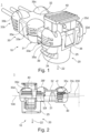
- Fig. 1 shows an electrical plug 1 configured to be connected to a mating electrical plug.
- the electrical plug 1 comprises a plug housing 10.
- the plug housing 10 comprises a plug portion 20 configured to be connected to the mating electrical plug along a plug direction 22.
- the plug housing 10 further comprises a base portion 30 based on a substantially cuboid basic shape.
- the base portion 30 comprises a base surface 31 and an opposite cover surface 32.
- the plug portion 20 is arranged on the base surface 31.
- the edges of the cuboid basic shape extending from the base surface 31 to the opposite cover surface 32 are respectively rounded, such that the base portion 30 comprises four roundings 33a, 33b, 33c, 33d, which in a cross-sectional plane 100 parallel to the base surface 31 respectively comprise a circular arc segment 34 having an angular dimension of at least 95°.
- the plug direction 22 extends substantially perpendicularly from the base surface 31.
- the radius ri (see Fig. 3 ) of the roundings 33a, 33b, 33c, 33d decreases respectively from a central plane 200, which lies centrally between the base surface 31 and the cover surface 32, towards the base surface 31.
- the radius ri of the roundings 33a, 33b, 33c, 33d also decreases respectively from the central plane 200, which lies centrally between the base surface 31 and the cover surface 32, towards the cover surface 32.
- Figs. 1, 2 , and 3 show that the roundings 33a, 33b, 33c, 33d respectively merge continuously into a spherical segment 35a, 35b, 35c, 35d along an axis, which extends perpendicularly from the base surface 31 to the cover surface 32.
- the spherical segments 35a, 35b, 35c, 35d are respectively adjacent to the cover surface 32.
- the base portion 30 comprises two further spherical segments 35e, 35f, which respectively have a substantially circular base surface, which is partially adjacent to the cover surface 32, wherein the part of the circular base surface, which is not adjacent to the cover surface 32, is extended in a direction towards the base surface 31.
- the base portion 30 comprises two further roundings 33e, 33f by extending the parts of the circular base surface, which are not adjacent to the cover surface 32.
- the two further spherical segments 35e, 35f are respectively arranged between two spherical segments 35a, 35b; 35c, 35d, such that six spherical segments 35a, 35b, 35c, 35d, 35e, 35f are arranged in two substantially parallel rows with respectively three spherical segments.
- the base portion 30 is wider between two opposite pairs of spherical segments 35a, 35e; 35d, 35f than between two other opposite pairs of spherical segments 35b, 350; 35c, 35f.
- the width is preferably measured in a central plane 200, which lies centrally between the base surface 31 and the cover surface 32.
- the height is preferably measured parallel to the plug direction 22.
- Figs. 1 to 4 show that the electrical plug 1 further comprises a locking element 40 configured to lock the electrical plug 1 to the mating electrical plug when the electrical plug 1 and the mating electrical plug are in a pre-assembled position.
- the locking element 40 is slidably supported in a direction parallel to the plug direction 22, wherein the locking element 40 is configured to lock the electrical plug 1 to the mating electrical plug by a movement in the plug direction 22.
- the cover surface 32 comprises an opening 38 in which the locking element 40 is slidably supported.
- Fig. 3 shows that the locking element 40 is adjacent to four spherical segments 35a, 35d, 35e, 35f. Although not shown, the four spherical segments 35a, 35d, 35e, 35f protrude further from the plug housing 10 in a direction perpendicular to the cover surface 32 than the locking element 40 in the locked state.
- Figs. 1 and 2 show that the roundings 33a, 33b, 33c, 33d, 33e, 33f respectively have at least one slot 39 which extends substantially parallel to the base surface 31.
- the electrical plug 1 shown in Figs. 1 to 4 is an airbag plug.
- the plug portion 20 comprises a cylindrical plug protrusion 25 comprising locking arms 26a, 26b with lugs 27a, 27b for cooperating with a locking groove of the mating electrical plug.
Landscapes
- Details Of Connecting Devices For Male And Female Coupling (AREA)
Abstract
The present disclosure relates to an electrical plug (1) configured to be connected to a mating electrical plug. The electrical plug (1) comprises a plug housing (10). The plug housing (10) comprises a plug portion (20) configured to be connected to the mating electrical plug along a plug direction (22). The plug housing (10) further comprises a base portion (30) based on a substantially cuboid basic shape. The base portion (30) comprises a base surface (31) and an opposite cover surface (32), wherein the plug portion (20) is arranged on the base surface (31). The edges of the cuboid basic shape extending from the base surface (31) to the opposite cover surface (32) are respectively rounded, such that the base portion (30) comprises at least four roundings (33a, 33b, 33c, 33d), wherein the roundings (33a, 33b, 33c, 33d) in a cross-sectional plane (100) parallel to the base surface (31) respectively comprise a circular arc segment (34) having an angular dimension of at least 95°.
Description
- The present disclosure relates to an electrical plug configured to be connected to a mating electrical plug.
- It is known that in vehicles, such as passenger cars and/or trucks, electrical plugs are used for various tasks. For example, electrical plugs are necessary in order to connect airbags in the vehicle passenger compartment to the corresponding signal transmitters, upon the signal of which the airbags are triggered. Furthermore, electrical plugs in the vehicle passenger compartment are generally also necessary in order to drive electrical adjustment mechanisms of vehicle seats. Various requirements are placed on the design and configuration of electrical plugs, in particular those in the vehicle passenger compartment.
- On the one hand, the aim is to reduce the installation space required for electrical plugs, for example in order to achieve more flexibility in the passenger compartment design of the vehicle in question. Specifically, a compact design of the electrical plugs is sought for this purpose.
- On the other hand, electrical plugs must be designed such that a low risk of injury is ensured. For example, in the case of electrical plugs in the vehicle passenger compartment, it is necessary that these produce no or at least no additional risk of injury in the event of contact with a person, for example as a result of a movement of the person and/or in the event of an impact of the vehicle. In this respect, there are, in particular, regulatory requirements which often prescribe specific structural features for the electrical plugs which are intended to minimise the risk of injury.
- The effort to implement a compact design of the electrical plugs is generally in conflict with the measures or structural features which are implemented with a view to reducing the risk of injury. For example, relatively large plug housings have to be used in order to provide sufficient space in the interior of the electrical plug for electrical components despite the required rounded edges which serve to reduce the risk of injury.
- It is therefore an aim of the present disclosure to provide an electrical plug which, on the one hand, has a compact design and, on the other hand, ensures a low risk of injury on contact with a person.
- This aim is achieved at least partially by an electrical plug according to the independent claim. Further aspects of the present disclosure are defined in the dependent claims.
- In particular, this aim is achieved by an electrical plug configured to be connected to a mating electrical plug. The electrical plug comprises a plug housing comprising a plug portion configured to be connected to the mating electrical plug along a plug direction. Further, the plug housing comprises a base portion based on a substantially cuboid basic shape. The base portion comprises a base surface and an opposite cover surface, wherein the plug portion is arranged on the base surface. The edges of the cuboid basic shape extending from the base surface to the opposite cover surface are respectively rounded, such that the base portion comprises at least four roundings, wherein the roundings in a cross-sectional plane parallel to the base surface respectively comprise a circular arc segment having an angular dimension of at least 95°.
- The plug housing may be formed in multiple parts. Preferably, the plug housing comprises at least one plastic housing part.
- The plug portion may comprise a protrusion protruding from the base surface, preferably perpendicular to the base surface. Alternatively, the plug portion may comprise a recess formed into the base surface. If the plug portion comprises said protrusion, it is understood that the mating electrical plug comprises a corresponding receptacle. However, if the plug portion comprises said recess, it is understood that the mating electrical plug comprises a correspondingly shaped protrusion configured to be connected to the recess.
- The base portion may be formed integrally with the plug portion. Alternatively, the base portion may be designed as a separate part.
- A "cuboid basic shape" may be defined as a three-dimensional body structure delimited by six rectangular surfaces, wherein each surface is parallel to its corresponding opposite surface. The "substantially cuboid basic shape" may deviate from the "cuboid basic shape" in the strictly geometric sense. For example, it is conceivable that two opposite surfaces of the "substantially cuboid basic shape" respectively comprise a certain curvature, thereby enabling easier gripping of the base portion. Further, it is conceivable that the surfaces of the "substantially cuboid basic shape" are not rectangular in the strictly geometric sense. After the edges of the substantially cuboid basic shape extending from the base surface to the opposite cover surface are respectively rounded, it is understood that the base portion per se does not have a "cuboid basic shape" in the strictly geometric sense and also does not have a "substantially cuboid basic shape", but rather is based on such as claimed.
- After the base portion is based on a substantially cuboid basic shape, the base surface of the base portion may correspond to the base surface of the substantially cuboid basic shape and the opposite cover surface of the base portion may correspond to the cover surface of the substantially cuboid basic shape.
- The cross-sectional plane being parallel to the base surface is preferably arranged substantially centrally between the base surface and the cover surface.
- The circular arc segment may be defined as a part of a circular arc delimited by two end points and the arc portion therebetween. The circular arc segment may be completely described by the associated circle center, the radius of the circle and the angular dimension delimiting the arc portion.
- The described electrical plug has several advantages over the prior art, these advantages being apparent to those skilled in the art in light of the present description.
- In particular, a more compact design may be achieved with the aid of the circular arc segment having an angular dimension of at least 95°, in particular over known electrical plugs whose circular arc segments generally have an angular dimension of 90°, and at the same time a low risk of injury may be ensured on contact with a person. Specifically, the circular arc segment having an angular dimension of at least 95° allows a reduction in the required installation space to be achieved in comparison with the known electrical plugs, with the same radius of the rounded edges. In particular, it may be avoided that relatively large plug housings have to be used in order to provide sufficient space in the interior of the electrical plug for electrical components despite the required rounded edges which serve to reduce the risk of injury.
- The plug direction preferably extends substantially perpendicularly from the base surface. For example, the plug portion may comprise a protrusion extending substantially perpendicularly from the base surface. By the plug direction extending substantially perpendicularly from the base surface, a plug connection may be achieved which, in particular parallel to the base surface, has a small freedom of movement. This has proven to be advantageous in that reliable electrical connections may be produced.
- Further preferably, the radius of the roundings decreases respectively from a central plane, which lies centrally between the base surface and the cover surface, towards the base surface. As a result, on the one hand, the dimensions of the plug housing may be kept smaller than if the radius does not decrease towards the base surface. On the other hand, a lower risk of injury may be achieved. One reason for the lower risk of injury is that abrupt transitions between adjacent surfaces, i.e. edges, in the region of the base surface may thus be avoided.
- In addition, preferably, the radius of the roundings decreases respectively from a central plane, which lies centrally between the base surface and the cover surface, towards the cover surface. As a result, on the one hand, the dimensions of the plug housing may be kept smaller than if the radius does not decrease towards the cover surface. On the other hand, a lower risk of injury may be achieved. One reason for the lower risk of injury is that abrupt transitions between adjacent surfaces, i.e. edges, in the region of the cover surface may thus be avoided.
- It is understood that if the cross-sectional plane being parallel to the base surface is arranged centrally between the base surface and the cover surface, the cross-sectional plane and the central plane then coincide.
- The roundings in the cross-sectional plane being parallel to the base surface may respectively comprise a circular arc segment having an angular dimension of at least 100°, preferably at least 120°, and more preferably at least 140°. These angular dimensions allow a more compact design, in particular over electrical plugs whose circular arc segments or rounded edges have an angular dimension of 90°, and at the same time a low risk of injury on contact with a person. One reason for this is that it may be avoided that larger plug housings have to be used in order to provide sufficient space in the interior of the electrical plug for electrical components despite the required rounded edges which serve to reduce the risk of injury.
- The roundings in the cross-sectional plane may respectively have a radius of at least 1 mm, preferably at least 2 mm, and more preferably at least 3 mm. It has been found that these radii can significantly minimise the risk of injury and, moreover, various regulatory regulations can be complied with. A specific example is ECE Regulation No. 17 on uniform regulations for the approval of motor vehicles. Further preferably, the roundings in the cross-sectional plane respectively have a radius of at most 5 mm. As a result, the installation space required for the electrical plug is kept low and at the same time the risk of injury is minimised and various regulatory regulations are complied with.
- The roundings may respectively merge continuously into a spherical segment along an axis, which extends perpendicularly from the base surface to the cover surface, wherein the spherical segments are preferably respectively adjacent to the cover surface. A spherical segment may be defined as a part of a sphere and/or a sphere surface defined by a sphere center, the radius of the sphere and the delimiting spherical portion. An additional protection against injuries may be achieved by the spherical segments. In particular, the spherical segments may prevent a person, for example in the event of an impact, from being injured by elements of the plug housing which are arranged on the cover surface and instead coming into contact with the spherical segments which have a reduced and/or predictable risk of injury.
- The base portion may comprise two further spherical segments, which respectively have a substantially circular base surface, which is partially adjacent to the cover surface, wherein the part of the circular base surface, which is not adjacent to the cover surface, is extended in a direction towards the base surface. By extending the part of the circular base surface, which is not adjacent to the cover surface, further roundings may be provided. Specifically, the base portion may comprise two further roundings by extending the part of the circular base surface, which is not adjacent to the cover surface. An improved protection against injuries may be achieved by the two further spherical segments and the two further roundings. In particular, the two further spherical segments may also prevent a person, for example in the event of an impact, from being injured by elements of the plug housing which are arranged on the cover surface and instead coming into contact with the spherical segments which have a reduced and/or predictable risk of injury in the case of base portions with larger cover surfaces.
- The two further spherical segments may respectively be arranged between two spherical segments, such that at least six spherical segments are arranged in two substantially parallel rows with respectively three spherical segments. Preferably, the two substantially parallel rows are substantially parallel to a longitudinal axis of the plug housing. A risk of injury by edges and/or protruding elements in the region of the cover surface may be further reduced by the two substantially parallel rows. This applies in particular to plug housings with a larger extension along the longitudinal axis than transversely to the longitudinal axis.
- The base portion may be wider and/or higher between two opposite pairs of spherical segments than between two other opposite pairs of spherical segments. The width is preferably measured in a central plane, which lies centrally between the base surface and the cover surface. The height is preferably measured parallel to the plug direction. An easier gripping of the base portion may be enabled by the base portion being wider and/or higher between two opposite pairs of spherical segments than between two other opposite pairs of spherical segments.
- The spherical segments may respectively have a radius of at least 1 mm, preferably at least 2 mm, and more preferably at least 3 mm. It has been found that these radii can minimise the risk of injury and, moreover, various regulatory provisions can be complied with. A specific example is ECE Regulation No. 17 on uniform regulations for the approval of motor vehicles. Further preferably, the spherical segments respectively have a radius of at most 5 mm. As a result, the installation space required for the electrical plug is kept low and at the same time the risk of injury is minimised and various regulatory provisions are complied with.
- The electrical plug may further comprise a locking element configured to lock the electrical plug to the mating electrical plug when the electrical plug and the mating electrical plug are in a pre-assembled position, wherein the locking element is preferably slidably supported in a direction parallel to the plug direction, wherein further preferably the locking element is configured to lock the electrical plug to the mating electrical plug by a movement in the plug direction. On the one hand, the locking element may ensure increased security against unintentional release of the plug connection. As a result, increased functional security is enabled. On the other hand, the locking element may prevent parts of the plug connection from flying around in the event of a vehicle impact and becoming sources of risk for vehicle occupants. Consequently, a further reduced risk of injury may also be achieved.
- The cover surface may comprise an opening in which the locking element is slidably supported. The opening may extend from the cover surface to the base surface. Consequently, the opening may be a through-hole. By the locking element being slidably supported in the opening, a reliable guidance of the locking element may be achieved.
- Preferably, the locking element is adjacent to four spherical segments. The four spherical segments may reduce a risk of injury by contact of a person with the locking element.
- The four spherical segments may protrude further from the plug housing in a direction perpendicular to the cover surface than the locking element in the locked state. As a result, a risk of injury by contact of a person with the locking element may be reduced, in particular.
- At least one of the roundings may have at least one slot which preferably extends substantially parallel to the base surface. A slot may be an elongate opening and/or an elongate recess. As a result of the at least one slot, the amount of material required for the electrical plug may be reduced without decisively increasing the risk of injury.
- Preferably, the electrical plug is an airbag plug, the plug portion comprising a substantially cylindrical plug protrusion, the cylindrical plug protrusion comprising locking arms with lugs for cooperating with a locking groove of the mating electrical plug, the cylindrical plug protrusion preferably further comprising an actuating element for interrupting a short-circuit state of a short-circuit element in the mating electrical plug. In order to lock the electrical plug to the mating electrical plug, it is possible that, when the electrical plug and the mating electrical plug are in a pre-assembled position, parts of the locking element are pushed between the plug protrusion and the locking arms. As a result, it is possible to prevent the locking arms from moving inward and/or outward and thereby releasing themselves from engagement with locking grooves of the mating electrical plug.
- The accompanying Figures are briefly described below:
-
Fig. 1 shows an electrical plug according to the present invention in perspective view; -
Fig. 2 shows a side view of the electrical plug; -
Fig. 3 shows a top view of the electrical plug, and -
Fig. 4 shows a further side view of the electrical plug. -
Fig. 1 shows anelectrical plug 1 configured to be connected to a mating electrical plug. Theelectrical plug 1 comprises aplug housing 10. Theplug housing 10 comprises aplug portion 20 configured to be connected to the mating electrical plug along aplug direction 22. Theplug housing 10 further comprises abase portion 30 based on a substantially cuboid basic shape. - As shown in
Figs. 1 and 2 , thebase portion 30 comprises abase surface 31 and anopposite cover surface 32. Theplug portion 20 is arranged on thebase surface 31. Furthermore, the edges of the cuboid basic shape extending from thebase surface 31 to theopposite cover surface 32 are respectively rounded, such that thebase portion 30 comprises fourroundings cross-sectional plane 100 parallel to thebase surface 31 respectively comprise acircular arc segment 34 having an angular dimension of at least 95°. - As further shown in
Figs. 1 and 2 , theplug direction 22 extends substantially perpendicularly from thebase surface 31. In addition, the radius ri (seeFig. 3 ) of theroundings central plane 200, which lies centrally between thebase surface 31 and thecover surface 32, towards thebase surface 31. In addition, the radius ri of theroundings central plane 200, which lies centrally between thebase surface 31 and thecover surface 32, towards thecover surface 32. - As shown in
Fig. 3 , theroundings cross-sectional plane 100, which is parallel to thebase surface 31, respectively comprise acircular arc segment 34 having an angular dimension of at least 140°. - In addition,
Figs. 1, 2 , and3 show that theroundings spherical segment base surface 31 to thecover surface 32. Here, thespherical segments cover surface 32. Furthermore, thebase portion 30 comprises two furtherspherical segments cover surface 32, wherein the part of the circular base surface, which is not adjacent to thecover surface 32, is extended in a direction towards thebase surface 31. As shown inFigs. 1 and 2 , thebase portion 30 comprises twofurther roundings cover surface 32. - As shown in
Fig. 3 , the two furtherspherical segments spherical segments spherical segments base portion 30 is wider between two opposite pairs ofspherical segments spherical segments 35b, 350; 35c, 35f. The width is preferably measured in acentral plane 200, which lies centrally between thebase surface 31 and thecover surface 32. The height is preferably measured parallel to theplug direction 22. -
Figs. 1 to 4 show that theelectrical plug 1 further comprises a lockingelement 40 configured to lock theelectrical plug 1 to the mating electrical plug when theelectrical plug 1 and the mating electrical plug are in a pre-assembled position. The lockingelement 40 is slidably supported in a direction parallel to theplug direction 22, wherein the lockingelement 40 is configured to lock theelectrical plug 1 to the mating electrical plug by a movement in theplug direction 22. As shown inFig. 1 , thecover surface 32 comprises anopening 38 in which thelocking element 40 is slidably supported.Fig. 3 shows that the lockingelement 40 is adjacent to fourspherical segments spherical segments plug housing 10 in a direction perpendicular to thecover surface 32 than the lockingelement 40 in the locked state. -
Figs. 1 and 2 show that theroundings slot 39 which extends substantially parallel to thebase surface 31. - The
electrical plug 1 shown inFigs. 1 to 4 is an airbag plug. Theplug portion 20 comprises acylindrical plug protrusion 25 comprising lockingarms lugs - In order to lock the
electrical plug 1 to the mating electrical plug, it is possible with a view toFig. 4 that, when theelectrical plug 1 and the mating electrical plug are in a pre-assembled position, parts of the lockingelement 40 are pushed between theplug protrusion 25 and the lockingarms arms -
- 1. An electrical plug (1) configured to be connected to a mating electrical plug, the electrical plug (1) comprising a plug housing (10), the plug housing (10) comprising:
- a plug portion (20) configured to be connected to the mating electrical plug along a plug direction (22); and
- a base portion (30) based on a substantially cuboid basic shape, the base portion (30) comprising a base surface (31) and an opposite cover surface (32), wherein the plug portion (20) is arranged on the base surface (31), wherein the edges of the cuboid basic shape extending from the base surface (31) to the opposite cover surface (32) are respectively rounded, such that the base portion (30) comprises at least four roundings (33a, 33b, 33c, 33d), wherein the roundings (33a, 33b, 33c, 33d) in a cross-sectional plane (100) parallel to the base surface (31) respectively comprise a circular arc segment (34) having an angular dimension of at least 95°.
- 2. Electrical plug (1) according to the preceding example, wherein the plug direction (22) extends substantially perpendicularly from the base surface (31).
- 3. Electrical plug (1) according to any one of the preceding examples, wherein the radius (ri) of the roundings (33a, 33b, 33c, 33d) decreases respectively from a central plane (200), which lies centrally between the base surface (31) and the cover surface (32), towards the base surface (31).
- 4. Electrical plug (1) according to any one of the preceding examples, wherein the radius (ri) of the roundings (33a, 33b, 33c, 33d) decreases respectively from a central plane (200), which lies centrally between the base surface (31) and the cover surface (32), towards the cover surface (32).
- 5. Electrical plug (1) according to any one of the preceding examples, wherein the roundings (33a, 33b, 33c, 33d) in the cross-sectional plane (100), which is parallel to the base surface (31), respectively have a circular arc segment (34) with an angular dimension of at least 100°, preferably at least 120°, and more preferably at least 140°.
- 6. Electrical plug (1) according to any one of the preceding examples, wherein the roundings (33a, 33b, 33c, 33d) in the cross-sectional plane (100) respectively have a radius (ri) of at least 1 mm, preferably at least 2 mm, and more preferably at least 3 mm.
- 7. Electrical plug (1) according to any one of the preceding examples, wherein the roundings (33a, 33b, 33c, 33d) respectively merge continuously into a spherical segment (35a, 35b, 35c, 35d) along an axis, which extends perpendicularly from the base surface (31) to the cover surface (32), wherein the spherical segments (35a, 35b, 35c, 35d) are preferably respectively adjacent to the cover surface (32).
- 8. Electrical plug (1) according to example 7, wherein the base portion (30) comprises two further spherical segments (35e, 35f), which respectively have a substantially circular base surface, which is partially adjacent to the cover surface (32), wherein the part of the circular base surface, which is not adjacent to the cover surface (32), is extended in a direction towards the base surface (31).
- 9. Electrical plug (1) according to the preceding example, wherein the two further spherical segments (35e, 35f) are respectively arranged between two spherical segments (35a, 35b; 35c, 35d), such that at least six spherical segments (35a, 35b, 35c, 35d, 35e, 35f) are arranged in two substantially parallel rows with respectively three spherical segments.
- 10. Electrical plug (1) according to the preceding example, wherein the base portion (30) between two opposite pairs of spherical segments (35a, 35e; 35d, 35f) is wider and/or higher than between two other opposite pairs of spherical segments (35b, 35e; 35c, 35f).
- 11. Electrical plug (1) according to any one of examples 7 to 10, wherein the spherical segments (35a, 35b, 35c, 35d, 35e, 35f) respectively have a radius (r2) of at least 1 mm, preferably at least 2 mm, and more preferably at least 3 mm.
- 12. Electrical plug (1) according to any one of the preceding examples, wherein the electrical plug (1) further comprises a locking element (40) configured to lock the electrical plug (1) to the mating electrical plug when the electrical plug (1) and the mating electrical plug are in a pre-assembled position, wherein the locking element (40) is preferably slidably supported in a direction parallel to the plug direction (22), wherein further preferably the locking element (40) is configured to lock the electrical plug (1) to the mating electrical plug by a movement in the plug direction (22).
- 13. Electrical plug (1) according to the preceding example, wherein the cover surface (32) comprises an opening (38) in which the locking element (40) is slidably supported.
- 14. Electrical plug (1) according to any one of examples 12 or 13 with any one of examples 7 to 11, wherein the locking element (40) is adjacent to four spherical segments (35a, 35d, 35e, 35f).
- 15. Electrical plug (1) according to the preceding example, wherein the four spherical segments (35a, 35d, 35e, 35f) protrude further from the plug housing (10) in a direction perpendicular to the cover surface (32) than the locking element (40) in the locked state.
- 16. Electrical plug (1) according to any one of the preceding examples, wherein at least one of the roundings (33a, 33b, 33c, 33d) has at least one slot (39) which preferably extends substantially parallel to the base surface (31).
- 17. Electrical plug (1) according to any one of the preceding examples, wherein the electrical plug (1) is an airbag plug, the plug portion (20) comprising a substantially cylindrical plug protrusion (25), the cylindrical plug protrusion (25) comprising locking arms (26a, 26b) with lugs (27a, 27b) for cooperating with a locking groove of the mating electrical plug, the cylindrical plug protrusion (25) preferably further comprising an actuating element for interrupting a short-circuit state of a short-circuit element in the mating electrical plug.
-
- 1
- Electrical plug
- 10
- Plug housing
- 20
- Plug portion
- 22
- plug direction
- 25
- plug protrusion
- 26a, 26b
- locking arms
- 27a, 27b
- lugs
- 30
- base portion
- 31
- base surface
- 32
- cover surface
- 33a, 33b, 33c, 33d, 33e, 33f
- roundings
- 34
- circular arc segment
- 35a, 35b, 35c, 35d, 35e, 35f
- spherical segments
- 38
- opening
- 39
- slot
- 40
- locking element
- 100
- cross-sectional plane
- 200
- central plane
Claims (15)
- An electrical plug (1) configured to be connected to a mating electrical plug, the electrical plug (1) comprising a plug housing (10), the plug housing (10) comprising:a plug portion (20) configured to be connected to the mating electrical plug along a plug direction (22); anda base portion (30) based on a substantially cuboid basic shape, the base portion (30) comprising a base surface (31) and an opposite cover surface (32), wherein the plug portion (20) is arranged on the base surface (31), wherein the edges of the cuboid basic shape extending from the base surface (31) to the opposite cover surface (32) are respectively rounded, such that the base portion (30) comprises at least four roundings (33a, 33b, 33c, 33d), wherein the roundings (33a, 33b, 33c, 33d) in a cross-sectional plane (100) parallel to the base surface (31) respectively comprise a circular arc segment (34) having an angular dimension of at least 95°.
- Electrical plug (1) according to the preceding claim, wherein the plug direction (22) extends substantially perpendicularly from the base surface (31).
- Electrical plug (1) according to any one of the preceding claims, wherein the radius (ri) of the roundings (33a, 33b, 33c, 33d) decreases respectively from a central plane (200), which lies centrally between the base surface (31) and the cover surface (32), towards the base surface (31).
- Electrical plug (1) according to any one of the preceding claims, wherein the radius (ri) of the roundings (33a, 33b, 33c, 33d) decreases respectively from a central plane (200), which lies centrally between the base surface (31) and the cover surface (32), towards the cover surface (32).
- Electrical plug (1) according to any one of the preceding claims, wherein the roundings (33a, 33b, 33c, 33d) in the cross-sectional plane (100), which is parallel to the base surface (31), respectively have a circular arc segment (34) with an angular dimension of at least 100°, preferably at least 120°, and more preferably at least 140°.
- Electrical plug (1) according to any one of the preceding claims, wherein the roundings (33a, 33b, 33c, 33d) in the cross-sectional plane (100) respectively have a radius (ri) of at least 1 mm, preferably at least 2 mm, and more preferably at least 3 mm.
- Electrical plug (1) according to any one of the preceding claims, wherein the roundings (33a, 33b, 33c, 33d) respectively merge continuously into a spherical segment (35a, 35b, 35c, 35d) along an axis, which extends perpendicularly from the base surface (31) to the cover surface (32), wherein the spherical segments (35a, 35b, 35c, 35d) are preferably respectively adjacent to the cover surface (32).
- Electrical plug (1) according to claim 7, wherein the base portion (30) comprises two further spherical segments (35e, 35f), which respectively have a substantially circular base surface, which is partially adjacent to the cover surface (32), wherein the part of the circular base surface, which is not adjacent to the cover surface (32), is extended in a direction towards the base surface (31).
- Electrical plug (1) according to the preceding claim, wherein the two further spherical segments (35e, 35f) are respectively arranged between two spherical segments (35a, 35b; 35c, 35d), such that at least six spherical segments (35a, 35b, 35c, 35d, 35e, 35f) are arranged in two substantially parallel rows with respectively three spherical segments.
- Electrical plug (1) according to the preceding claim, wherein the base portion (30) between two opposite pairs of spherical segments (35a, 35e; 35d, 35f) is wider and/or higher than between two other opposite pairs of spherical segments (35b, 35e; 35c, 35f).
- Electrical plug (1) according to any one of claims 7 to 10, wherein the spherical segments (35a, 35b, 35c, 35d, 35e, 35f) respectively have a radius (r2) of at least 1 mm, preferably at least 2 mm, and more preferably at least 3 mm.
- Electrical plug (1) according to any one of the preceding claims, wherein the electrical plug (1) further comprises a locking element (40) configured to lock the electrical plug (1) to the mating electrical plug when the electrical plug (1) and the mating electrical plug are in a pre-assembled position, wherein the locking element (40) is preferably slidably supported in a direction parallel to the plug direction (22), wherein further preferably the locking element (40) is configured to lock the electrical plug (1) to the mating electrical plug by a movement in the plug direction (22).
- Electrical plug (1) according to the preceding claim, wherein the cover surface (32) comprises an opening (38) in which the locking element (40) is slidably supported.
- Electrical plug (1) according to any one of claims 12 or 13 with any one of claims 7 to 11, wherein the locking element (40) is adjacent to four spherical segments (35a, 35d, 35e, 35f).
- Electrical plug (1) according to the preceding claim, wherein the four spherical segments (35a, 35d, 35e, 35f) protrude further from the plug housing (10) in a direction perpendicular to the cover surface (32) than the locking element (40) in the locked state.
Applications Claiming Priority (1)
| Application Number | Priority Date | Filing Date | Title |
|---|---|---|---|
| DE202023104385.2U DE202023104385U1 (en) | 2023-08-02 | 2023-08-02 | Electrical plug |
Publications (1)
| Publication Number | Publication Date |
|---|---|
| EP4503345A1 true EP4503345A1 (en) | 2025-02-05 |
Family
ID=92174940
Family Applications (1)
| Application Number | Title | Priority Date | Filing Date |
|---|---|---|---|
| EP24192387.9A Pending EP4503345A1 (en) | 2023-08-02 | 2024-08-01 | Electrical plug |
Country Status (2)
| Country | Link |
|---|---|
| EP (1) | EP4503345A1 (en) |
| DE (1) | DE202023104385U1 (en) |
Citations (3)
| Publication number | Priority date | Publication date | Assignee | Title |
|---|---|---|---|---|
| AT6129U1 (en) * | 1999-07-22 | 2003-04-25 | Egston Eggenburger Syst Elektr | ELECTRICAL / ELECTRONIC DEVICE |
| US10236640B2 (en) * | 2016-11-30 | 2019-03-19 | Tyco Electronics France Sas | Electrical connector for a safety restraint system |
| CN211829333U (en) * | 2020-03-23 | 2020-10-30 | 杭州柏列得电器有限公司 | Installation cover for preventing binding post from being separated |
Family Cites Families (4)
| Publication number | Priority date | Publication date | Assignee | Title |
|---|---|---|---|---|
| DE10205535A1 (en) * | 2002-02-11 | 2003-08-28 | Amphenol Tuchel Elect | Electric plug connector used between socket and electric control for car personal restrain system |
| DE102005021375B4 (en) * | 2005-05-04 | 2007-02-01 | Yazaki Europe Ltd., Hemel Hempstead | Connectors, in particular for airbag ignition systems |
| WO2014087430A1 (en) * | 2012-12-07 | 2014-06-12 | Tyco Electronics Uk Ltd | Electrical connector and assembly therewith having a spring-apart function |
| JP7308897B2 (en) * | 2021-10-15 | 2023-07-14 | 三菱電機株式会社 | electronic device |
-
2023
- 2023-08-02 DE DE202023104385.2U patent/DE202023104385U1/en active Active
-
2024
- 2024-08-01 EP EP24192387.9A patent/EP4503345A1/en active Pending
Patent Citations (3)
| Publication number | Priority date | Publication date | Assignee | Title |
|---|---|---|---|---|
| AT6129U1 (en) * | 1999-07-22 | 2003-04-25 | Egston Eggenburger Syst Elektr | ELECTRICAL / ELECTRONIC DEVICE |
| US10236640B2 (en) * | 2016-11-30 | 2019-03-19 | Tyco Electronics France Sas | Electrical connector for a safety restraint system |
| CN211829333U (en) * | 2020-03-23 | 2020-10-30 | 杭州柏列得电器有限公司 | Installation cover for preventing binding post from being separated |
Also Published As
| Publication number | Publication date |
|---|---|
| DE202023104385U1 (en) | 2024-11-05 |
Similar Documents
| Publication | Publication Date | Title |
|---|---|---|
| US9840223B2 (en) | Front airbag for vehicle | |
| EP3166185B1 (en) | Spring-lock connector | |
| EP3171459A1 (en) | Electrical connector with a terminal position assurance device | |
| EP1309038A1 (en) | Orientationless squib connector assembly for automotive air bag assemblies | |
| US10266143B2 (en) | Steering wheel | |
| US11400875B2 (en) | Holder and wire harness | |
| US5882224A (en) | Squib connector socker assembly having shorting clip for automotive air bags | |
| US20170282835A1 (en) | Steering wheel | |
| US10355465B2 (en) | Reduced height relay block for vehicle power distribution device | |
| EP2380244B1 (en) | Shorting clip for an airbag ignition system | |
| CN102370292A (en) | Seat belt buckle and seat belt system for vehicle | |
| EP1378970B1 (en) | Connecting structure of connectors | |
| US11001183B2 (en) | Adapter for a grab handle in the interior of a motor vehicle | |
| US7744432B2 (en) | Squib connector connecting structure of airbag inflator | |
| JP2000350331A (en) | Mounting structure of electrical junction box for automobile | |
| US11146016B2 (en) | Connector | |
| US20240396262A1 (en) | Electrical Plug Connector Assembly | |
| KR102666878B1 (en) | Connector | |
| CN116890643B (en) | Instrument board structure | |
| CN115347415A (en) | Electrical connector comprising a connector position assurance element | |
| CN109070837B (en) | cover for belt | |
| EP3979429B1 (en) | Electrical connector with locking spring | |
| JP7639048B2 (en) | Wire protection structure | |
| KR101034140B1 (en) | Variable tether device for curtain airbag | |
| CN215513588U (en) | Side airbag module and combination system for a vehicle |
Legal Events
| Date | Code | Title | Description |
|---|---|---|---|
| PUAI | Public reference made under article 153(3) epc to a published international application that has entered the european phase |
Free format text: ORIGINAL CODE: 0009012 |
|
| STAA | Information on the status of an ep patent application or granted ep patent |
Free format text: STATUS: THE APPLICATION HAS BEEN PUBLISHED |
|
| AK | Designated contracting states |
Kind code of ref document: A1 Designated state(s): AL AT BE BG CH CY CZ DE DK EE ES FI FR GB GR HR HU IE IS IT LI LT LU LV MC ME MK MT NL NO PL PT RO RS SE SI SK SM TR |
|
| STAA | Information on the status of an ep patent application or granted ep patent |
Free format text: STATUS: REQUEST FOR EXAMINATION WAS MADE |
|
| 17P | Request for examination filed |
Effective date: 20250718 |