EP4503342A1 - Terminal body, terminal and connector - Google Patents
Terminal body, terminal and connector Download PDFInfo
- Publication number
- EP4503342A1 EP4503342A1 EP24192043.8A EP24192043A EP4503342A1 EP 4503342 A1 EP4503342 A1 EP 4503342A1 EP 24192043 A EP24192043 A EP 24192043A EP 4503342 A1 EP4503342 A1 EP 4503342A1
- Authority
- EP
- European Patent Office
- Prior art keywords
- terminal
- mating
- mating part
- plate
- terminal body
- Prior art date
- Legal status (The legal status is an assumption and is not a legal conclusion. Google has not performed a legal analysis and makes no representation as to the accuracy of the status listed.)
- Pending
Links
Images




Classifications
-
- H—ELECTRICITY
- H01—ELECTRIC ELEMENTS
- H01R—ELECTRICALLY-CONDUCTIVE CONNECTIONS; STRUCTURAL ASSOCIATIONS OF A PLURALITY OF MUTUALLY-INSULATED ELECTRICAL CONNECTING ELEMENTS; COUPLING DEVICES; CURRENT COLLECTORS
- H01R13/00—Details of coupling devices of the kinds covered by groups H01R12/70 or H01R24/00 - H01R33/00
- H01R13/02—Contact members
- H01R13/10—Sockets for co-operation with pins or blades
- H01R13/11—Resilient sockets
-
- H—ELECTRICITY
- H01—ELECTRIC ELEMENTS
- H01R—ELECTRICALLY-CONDUCTIVE CONNECTIONS; STRUCTURAL ASSOCIATIONS OF A PLURALITY OF MUTUALLY-INSULATED ELECTRICAL CONNECTING ELEMENTS; COUPLING DEVICES; CURRENT COLLECTORS
- H01R13/00—Details of coupling devices of the kinds covered by groups H01R12/70 or H01R24/00 - H01R33/00
- H01R13/40—Securing contact members in or to a base or case; Insulating of contact members
- H01R13/42—Securing in a demountable manner
- H01R13/428—Securing in a demountable manner by resilient locking means on the contact members; by locking means on resilient contact members
- H01R13/434—Securing in a demountable manner by resilient locking means on the contact members; by locking means on resilient contact members by separate resilient locking means on contact member, e.g. retainer collar or ring around contact member
-
- H—ELECTRICITY
- H01—ELECTRIC ELEMENTS
- H01R—ELECTRICALLY-CONDUCTIVE CONNECTIONS; STRUCTURAL ASSOCIATIONS OF A PLURALITY OF MUTUALLY-INSULATED ELECTRICAL CONNECTING ELEMENTS; COUPLING DEVICES; CURRENT COLLECTORS
- H01R13/00—Details of coupling devices of the kinds covered by groups H01R12/70 or H01R24/00 - H01R33/00
- H01R13/02—Contact members
- H01R13/10—Sockets for co-operation with pins or blades
- H01R13/11—Resilient sockets
- H01R13/113—Resilient sockets co-operating with pins or blades having a rectangular transverse section
-
- H—ELECTRICITY
- H01—ELECTRIC ELEMENTS
- H01R—ELECTRICALLY-CONDUCTIVE CONNECTIONS; STRUCTURAL ASSOCIATIONS OF A PLURALITY OF MUTUALLY-INSULATED ELECTRICAL CONNECTING ELEMENTS; COUPLING DEVICES; CURRENT COLLECTORS
- H01R13/00—Details of coupling devices of the kinds covered by groups H01R12/70 or H01R24/00 - H01R33/00
- H01R13/02—Contact members
- H01R13/15—Pins, blades or sockets having separate spring member for producing or increasing contact pressure
- H01R13/187—Pins, blades or sockets having separate spring member for producing or increasing contact pressure with spring member in the socket
-
- H—ELECTRICITY
- H01—ELECTRIC ELEMENTS
- H01R—ELECTRICALLY-CONDUCTIVE CONNECTIONS; STRUCTURAL ASSOCIATIONS OF A PLURALITY OF MUTUALLY-INSULATED ELECTRICAL CONNECTING ELEMENTS; COUPLING DEVICES; CURRENT COLLECTORS
- H01R13/00—Details of coupling devices of the kinds covered by groups H01R12/70 or H01R24/00 - H01R33/00
- H01R13/40—Securing contact members in or to a base or case; Insulating of contact members
- H01R13/42—Securing in a demountable manner
- H01R13/428—Securing in a demountable manner by resilient locking means on the contact members; by locking means on resilient contact members
-
- H—ELECTRICITY
- H01—ELECTRIC ELEMENTS
- H01R—ELECTRICALLY-CONDUCTIVE CONNECTIONS; STRUCTURAL ASSOCIATIONS OF A PLURALITY OF MUTUALLY-INSULATED ELECTRICAL CONNECTING ELEMENTS; COUPLING DEVICES; CURRENT COLLECTORS
- H01R13/00—Details of coupling devices of the kinds covered by groups H01R12/70 or H01R24/00 - H01R33/00
- H01R13/62—Means for facilitating engagement or disengagement of coupling parts or for holding them in engagement
- H01R13/629—Additional means for facilitating engagement or disengagement of coupling parts, e.g. aligning or guiding means, levers, gas pressure electrical locking indicators, manufacturing tolerances
-
- H—ELECTRICITY
- H01—ELECTRIC ELEMENTS
- H01R—ELECTRICALLY-CONDUCTIVE CONNECTIONS; STRUCTURAL ASSOCIATIONS OF A PLURALITY OF MUTUALLY-INSULATED ELECTRICAL CONNECTING ELEMENTS; COUPLING DEVICES; CURRENT COLLECTORS
- H01R13/00—Details of coupling devices of the kinds covered by groups H01R12/70 or H01R24/00 - H01R33/00
- H01R13/62—Means for facilitating engagement or disengagement of coupling parts or for holding them in engagement
- H01R13/639—Additional means for holding or locking coupling parts together, after engagement, e.g. separate keylock, retainer strap
-
- H—ELECTRICITY
- H01—ELECTRIC ELEMENTS
- H01R—ELECTRICALLY-CONDUCTIVE CONNECTIONS; STRUCTURAL ASSOCIATIONS OF A PLURALITY OF MUTUALLY-INSULATED ELECTRICAL CONNECTING ELEMENTS; COUPLING DEVICES; CURRENT COLLECTORS
- H01R4/00—Electrically-conductive connections between two or more conductive members in direct contact, i.e. touching one another; Means for effecting or maintaining such contact; Electrically-conductive connections having two or more spaced connecting locations for conductors and using contact members penetrating insulation
- H01R4/02—Soldered or welded connections
- H01R4/029—Welded connections
Definitions
- the present invention relates to a terminal body, a terminal comprising the terminal body and a connector comprising the terminal.
- the terminal of a high-voltage connector typically includes a terminal body and a pair of elastic contacts.
- the terminal body usually includes two terminal plates facing each other and a connecting part connected between one sides of the two terminal plates.
- the pair of elastic contacts are installed on the inner surfaces facing each other of two terminal plates, used to clamp a mating terminal inserted between them, in order to achieve electrical connection between the terminal and the mating terminal.
- the terminal body is usually an integral stamped piece, and the connecting part between two terminal plates needs to be bent 180 degrees.
- some metal materials such as aluminum or aluminum alloys, are prone to cracking when bent at large angles, which can reduce the conductivity of the terminal.
- the present invention has been made to overcome or alleviate at least one aspect of the above mentioned disadvantages.
- a terminal body comprising of a first terminal plate comprising a first mating part and a first welding part connected to the first mating part; and a second terminal plate comprising a second mating part and a second welding part connected to the second mating part.
- the first mating part and the second mating part are spaced relative to each other in a height direction of the terminal body to allow for the insertion of a mating terminal; the first welding part is stacked and welded on the second welding part, and the first terminal plate and the second terminal plate are two independent components formed separately.
- the first mating part and the first welding part are in a flat shape and perpendicular to the height direction of the terminal body; the first terminal plate further comprises a bending part which is connected between the first mating part and the first welding part.
- the bending part is bent 90 degrees relative to the first mating part and the first welding part, so that the first welding part is at a different height from the first welding part.
- the second mating part and the second welding part are in a flat shape and perpendicular to the height direction of the terminal body; the second mating part and the second welding part are at the same height, so that the entire second terminal plate is in a flat shape.
- the first terminal plate has a front end and a rear end opposite to each other in a longitudinal direction of the terminal body, and the first mating part and the first welding part are respectively located at the front end and rear end of the first terminal plate;
- the second terminal plate has a front end and a rear end opposite to each other in the longitudinal direction of the terminal body, and the second mating part and the second welding part are respectively located at the front end and rear end of the second terminal plate.
- the first terminal plate is an integral aluminum stamped component or an integral aluminum alloy stamped component
- the second terminal plate is an integral aluminum stamped component or an integral aluminum alloy stamped component.
- a terminal comprising of: the above terminal body; and a pair of elastic contacts which are installed on the inner surfaces facing each other of the first mating part and the second mating part, respectively.
- the pair of elastic contacts are used to clamp the mating terminal inserted between them, in order to achieve electrical connection between the terminal and the mating terminal.
- the elastic contact comprises: a first side edge part which extends along the longitudinal direction of the terminal body; a second side edge part which extends along the longitudinal direction of the terminal body; and an elastic contact arm which is connected between the first side edge part and the second side edge part.
- the elastic contact arm is used for electrical contact with the inserted mating terminal to achieve electrical connection between the terminal and the mating terminal.
- the elastic contact comprises multiple elastic contact arms, which are arranged in a row along the longitudinal direction of the terminal body for simultaneous electrical contact with the inserted mating terminal.
- the first side edge parts of the pair of elastic contacts are fixed to the inner surfaces of the first mating part and the second mating part, respectively; the second side edge parts of the pair of elastic contacts are slidably supported on the inner surfaces of the first mating part and the second mating part, respectively.
- the first mating part have two sides opposite to each other in a transverse direction of the terminal body, and a pair of first protrusions are formed on the inner surface of the first mating part and respectively located at the two sides of the first mating part, to support the mating terminal inserted between the pair of elastic contacts, to prevent the elastic contact arm from being excessively compressed by the mating terminal;
- the second mating part have two sides opposite to each other in the transverse direction of the terminal body, and a pair of second protrusions are formed on the inner surface of the second mating part and respectively located at the two sides of the second mating part, to support the mating terminal inserted between the pair of elastic contacts, to prevent the elastic contact arm from being excessively compressed by the mating terminal.
- a first rib is formed on the inner surface of the first mating part, which extends along the longitudinal direction of the terminal body to support the elastic contact arm of one elastic contact, to prevent excessive deformation of the elastic contact arm of the one elastic contact;
- a second rib is formed on the inner surface of the second mating part, which extends along the longitudinal direction of the terminal body to support the elastic contact arm of the other elastic contact, to prevent excessive deformation of the elastic contact arm of the other elastic contact.
- an insertion port is defined between the first mating part and the second mating part that allows the mating terminal to be inserted along the transverse direction of the terminal body.
- the terminal further comprises a locking member which is fitted on the ends of the first mating part and the second mating part to lock the terminal into a connector housing.
- the locking member comprises: a top plate which is fixed to the outer side of the first mating part; a bottom plate which is fixed to the outer side of the second mating part; and an end plate which is connected between the top plate and the bottom plate.
- the end plate is fixed to the ends of the first mating part and the second mating part.
- the first mating part has two side edges opposite to each other in the transverse direction of the terminal body, and a first positioning slot and a first limiting tongue extending into the first positioning slot are formed on each side edge of the first mating part; a first elastic clamping part bent inward into a C-shape is formed on the side of the top plate of the locking member, and the first elastic clamping part is positioned in the first positioning slot and clamps the first limiting tongue.
- the second mating part has two side edges opposite to each other in the transverse direction of the terminal body, and a second positioning slot and a second limiting tongue extending into the second positioning slot are formed on each side edge of the second mating part; a second elastic clamping part bent inward into a C-shape is formed on the side of the bottom plate of the locking member, and the second elastic clamping part is positioned in the second positioning slot and clamps the second limiting tongue.
- a first elastic locking piece and a second elastic locking piece are respectively formed on the top plate and bottom plate of the locking member, the first elastic locking piece and the second elastic locking piece are used to engage with the connector housing to lock the terminal in the connector housing.
- a first guide rib and a second guide rib are respectively formed on the outsides of the top plate and the bottom plate of the locking member, the first guide rib and the second guide rib are used to respectively cooperate with a first guide slot and a second guide slot on the connector housing, to guide the terminal to be inserted into the connector housing.
- a first positioning protrusion and a second positioning protrusion are respectively formed on the end faces of the first mating part and the second mating part, and a first positioning slot hole and a second positioning slot hole are respectively formed in the end plate of the locking member, the first positioning protrusion and the second positioning protrusion are respectively fitted into the first positioning slot hole and the second positioning slot hole.
- a connector comprising of a connector housing; and the above terminal inserted into the connector housing.
- the terminal body comprises two separate terminal plates formed separately, and the two terminal plates are welded together, thereby avoiding the problem of large angle bending of the terminal body and improving the conductivity of the terminal.
- a terminal body comprising of a first terminal plate comprising a first mating part and a first welding part connected to the first mating part; and a second terminal plate comprising a second mating part and a second welding part connected to the second mating part.
- the first mating part and the second mating part are spaced relative to each other in a height direction of the terminal body to allow for the insertion of a mating terminal; the first welding part is stacked and welded on the second welding part, and the first terminal plate and the second terminal plate are two independent components formed separately.
- a terminal comprising of: the above terminal body; and a pair of elastic contacts which are installed on the inner surfaces facing each other of the first mating part and the second mating part, respectively.
- the pair of elastic contacts are used to clamp the mating terminal inserted between them, in order to achieve electrical connection between the terminal and the mating terminal.
- a connector comprising of a connector housing; and the above terminal inserted into the connector housing.
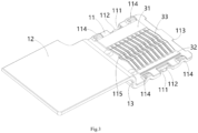
- Figure 1 shows an illustrative perspective view of a terminal according to an exemplary embodiment of the present invention
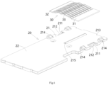
- Figure 2 shows an illustrative exploded view according to an exemplary embodiment of the present invention
- Figure 3 shows an illustrative assembly view of the first terminal plate 10 and one elastic contact 30 according to an exemplary embodiment of the present invention
- Figure 4 shows an illustrative exploded view of the first terminal plate 10 and one elastic contact 30 according to an exemplary embodiment of the present invention
- Figure 5 shows an illustrative assembly view of a second terminal plate 20 and the other elastic contact 30 according to an exemplary embodiment of the present invention
- Figure 6 shows a schematic diagram of the disassembly of the second terminal plate 20 and the other elastic contact 30 according to an exemplary embodiment of the present invention.
- a terminal body in an exemplary embodiment of the present invention, includes: a first terminal plate 10 and a second terminal plate 20.
- the first terminal plate 10 includes a first mating part 11 and a first welding part 12 connected to the first mating part 11.
- the second terminal plate 20 includes a second mating part 21 and a second welding part 22 connected to the second mating part 21.
- the first mating part 11 and the second mating part 21 are spaced relative to each other in the height direction Z of the terminal body to allow a mating terminal (not shown) to be inserted.
- the first welding part 12 is stacked on the second welding part 22 and welded together, and the first terminal plate 10 and the second terminal plate 20 are two independent components formed separately.
- the first mating part 11 and the first welding part 12 are in a flat shape and perpendicular to the height direction Z of the terminal body.
- the first terminal plate 10 also includes a bending part 13, which is connected between the first mating part 11 and the first welding part 12. The bending part 13 is bent 90 degrees relative to the first mating part 11 and the first welding part 12, so that the first welding part 12 and the first welding part 12 are at different heights.
- the second mating part 21 and the second welding part 22 are in a flat shape and perpendicular to the height direction Z of the terminal body.
- the second mating part 21 and the second welding part 22 are at the same height, so that the entire second terminal plate 20 is in a flat shape.
- the first terminal plate 10 has a front end and a rear end opposite to each other in the longitudinal direction Y of the terminal body, with the first mating part 11 and the first welding part 12 located at the front end and rear end of the first terminal plate 10, respectively.
- the second terminal plate 20 has front and rear ends opposite to each other in the longitudinal direction Y of the terminal body, and the second mating part 21 and the second welding part 22 are respectively located at the front and rear ends of the second terminal plate 20.
- the first terminal plate 10 is an integral aluminum stamped component or an integral aluminum alloy stamped component.
- the second terminal plate 20 is an integral aluminum stamped component or an integral aluminum alloy stamped component.
- a terminal is also disclosed.
- the terminal includes: the aforementioned terminal body and a pair of elastic contacts 30.
- the pair of elastic contacts 30 are respectively installed on the inner surfaces facing each other of the first mating part 11 and the second mating part 21.
- the pair of elastic contacts 30 are used to clamp a mating terminal inserted between them, in order to achieve electrical connection between the terminal and the mating terminal.
- the elastic contact 30 comprises: a first side edge part 31, a second side edge part 32, and an elastic contact arm 33.
- the first side edge part 31 extends along the longitudinal direction Y of the terminal body.
- the second side edge part 32 extends along the longitudinal Y of the terminal body and is separated from the first side edge part 31 on the transverse X of the terminal body.
- the elastic contact arm 33 is connected between the first side edge part 31 and the second side edge part 32. The elastic contact arm 33 is used for electrical contact with the inserted mating terminal to achieve electrical connection between the terminal and the mating terminal.
- the elastic contact 30 comprises multiple elastic contact arms 33, which are arranged in a row along the longitudinal direction Y of the terminal body for simultaneous electrical contact with the inserted mating terminal.
- the first side edge parts 31 of the pair of elastic contacts 30 are fixed to the inner surfaces of the first mating part 11 and the second mating part 21, respectively.
- the second side edge parts 32 of the pair of elastic contacts 30 are slidably supported on the inner surfaces of the first mating part 11 and the second mating part 21, respectively.
- the first mating part 11 have two sides opposite to each other in a transverse direction X of the terminal body, and a pair of first protrusions 114 are formed on the inner surface of the first mating part 11 and respectively located at two sides of the first mating part 11, to support the mating terminal inserted between the pair of elastic contacts 30, to prevent the elastic contact arm 33 from being excessively compressed by the mating terminal.
- the second mating part 21 have two sides opposite to each other in the transverse direction X of the terminal body, and a pair of second protrusions 214 are formed on the inner surface of the second mating part 21 and respectively located at two sides of second mating part 21, to support the mating terminal inserted between the pair of elastic contacts 30, to prevent the elastic contact arm 33 from being excessively compressed by the mating terminal.
- a first rib 115 is formed on the inner surface of the first mating part 11.
- the first rib 115 extends along the longitudinal direction Y of the terminal body to support the elastic contact arm 33 of one elastic contact 30, in order to prevent excessive deformation of the elastic contact arm 33 of one elastic contact 30.
- a second rib 215 is formed on the inner surface of the second mating part 21, which extends along the longitudinal direction Y of the terminal body to support the elastic contact arm 33 of the other elastic contact 30, in order to prevent excessive deformation of the elastic contact arm 33 of the other elastic contact 30.
- an insertion port 101 is defined between the first mating part 11 and the second mating part 21 that allows the mating terminal to be inserted along the transverse direction X of the terminal body.
- the terminal further comprises a locking member 40, which is mounted on the ends of the first mating part 11 and the second mating part 21 to lock the terminal into the connector housing (not shown).
- the locking member 40 comprises a top plate 41, a bottom plate 42, and an end plate 43.
- the top plate 41 is fixed to the outer side of the first mating part 11.
- the bottom plate 42 is fixed to the outer side of the second mating part 21.
- the end plate 43 is connected between the top plate 41 and the bottom plate 42.
- the end plate 43 is fixed to the ends of the first mating part 11 and the second mating part 21.
- the first mating part 11 has two side edges opposite to each other in the transverse direction X of the terminal body, and a first positioning slot 111 and a first limiting tongue 112 extending into the first positioning slot 111 are formed on each of two side edges of the first mating part 11.
- a first elastic clamping part 411 is formed on the side of the top plate 41 of the locking member 40, which is bent inward into a C-shaped shape. The first elastic clamping part 411 is positioned in the first positioning slot 111 and grips the first limiting tongue 112.
- the second mating part 21 has two side edges opposite to each other in the transverse direction X of the terminal body, and a second positioning slot 211 and a second limiting tongue 212 extending into the second positioning slot 211 are formed on each of two side edges of the second mating part 21.
- a second elastic clamping part 421 is formed on the side of the bottom plate 42 of the locking member 40, which is bent inward into a C-shaped shape. The second elastic clamping part 421 is positioned in the second positioning slot 211 and grips the second limiting tongue 212.
- a first elastic locking piece 410 and a second elastic locking piece 420 are respectively formed on the top plate 41 and bottom plate 42 of the locking member 40.
- the first elastic locking piece 410 and the second elastic locking piece 420 are used to engage with the connector housing to lock the terminal in the connector housing.
- a first guide rib 412 and a second guide rib 422 are formed on the outside of the top plate 41 and bottom plate 42 of the locking member 40, respectively.
- the first guide rib 412 and the second guide rib 422 are used to mate with a first guide slot and a second guide slot in the connector housing to guide the terminal to be inserted into the connector housing.
- a first positioning protrusion 113 and a second positioning protrusion 213 are formed on the end faces of the first mating part 11 and the second mating part 21, respectively.
- a first positioning slot hole 413 and a second positioning slot hole 423 are formed in the end plate 43 of the locking member 40. The first positioning protrusion 113 and the second positioning protrusion 213 are fitted into the first positioning slot hole 413 and the second positioning slot hole 423, respectively.
- a connector is also disclosed.
- the connector includes a connector housing and the aforementioned terminal.
- the terminal is inserted into the connector housing.
Landscapes
- Coupling Device And Connection With Printed Circuit (AREA)
- Connector Housings Or Holding Contact Members (AREA)
Abstract
The present invention discloses a terminal body, a terminal and a connector. The terminal body comprises of a first terminal plate (10) comprising a first mating part (11) and a first welding part (12) connected to the first mating part (11); and a second terminal plate (20) comprising a second mating part (21) and a second welding part (22) connected to the second mating part (21). The first mating part (11) and the second mating part (21) are spaced relative to each other in a height direction (Z) of the terminal body to allow for the insertion of a mating terminal; the first welding part (12) is stacked and welded on the second welding part (22), and the first terminal plate (10) and the second terminal plate (20) are two independent components formed separately. In the present invention, the terminal body comprises two separate terminal plates formed separately, and the two terminal plates are welded together, thereby avoiding the problem of large angle bending of the terminal body and improving the conductivity of the terminal.
Description
- This application claims the benefit of Chinese Patent Application No.
CN202322084905.9 filed on August 3, 2023 - The present invention relates to a terminal body, a terminal comprising the terminal body and a connector comprising the terminal.
- In the prior art, the terminal of a high-voltage connector typically includes a terminal body and a pair of elastic contacts. The terminal body usually includes two terminal plates facing each other and a connecting part connected between one sides of the two terminal plates. The pair of elastic contacts are installed on the inner surfaces facing each other of two terminal plates, used to clamp a mating terminal inserted between them, in order to achieve electrical connection between the terminal and the mating terminal.
- In the prior art, the terminal body is usually an integral stamped piece, and the connecting part between two terminal plates needs to be bent 180 degrees. However, some metal materials, such as aluminum or aluminum alloys, are prone to cracking when bent at large angles, which can reduce the conductivity of the terminal.
- The present invention has been made to overcome or alleviate at least one aspect of the above mentioned disadvantages.
- According to an aspect of the present invention, there is provided a terminal body. The terminal body comprises of a first terminal plate comprising a first mating part and a first welding part connected to the first mating part; and a second terminal plate comprising a second mating part and a second welding part connected to the second mating part. The first mating part and the second mating part are spaced relative to each other in a height direction of the terminal body to allow for the insertion of a mating terminal; the first welding part is stacked and welded on the second welding part, and the first terminal plate and the second terminal plate are two independent components formed separately.
- According to an exemplary embodiment of the present invention, the first mating part and the first welding part are in a flat shape and perpendicular to the height direction of the terminal body; the first terminal plate further comprises a bending part which is connected between the first mating part and the first welding part. The bending part is bent 90 degrees relative to the first mating part and the first welding part, so that the first welding part is at a different height from the first welding part.
- According to another exemplary embodiment of the present invention, the second mating part and the second welding part are in a flat shape and perpendicular to the height direction of the terminal body; the second mating part and the second welding part are at the same height, so that the entire second terminal plate is in a flat shape.
- According to another exemplary embodiment of the present invention, the first terminal plate has a front end and a rear end opposite to each other in a longitudinal direction of the terminal body, and the first mating part and the first welding part are respectively located at the front end and rear end of the first terminal plate; the second terminal plate has a front end and a rear end opposite to each other in the longitudinal direction of the terminal body, and the second mating part and the second welding part are respectively located at the front end and rear end of the second terminal plate.
- According to another exemplary embodiment of the present invention, the first terminal plate is an integral aluminum stamped component or an integral aluminum alloy stamped component; the second terminal plate is an integral aluminum stamped component or an integral aluminum alloy stamped component.
- According to another aspect of the present invention, there is provided a terminal. The terminal comprises of: the above terminal body; and a pair of elastic contacts which are installed on the inner surfaces facing each other of the first mating part and the second mating part, respectively. The pair of elastic contacts are used to clamp the mating terminal inserted between them, in order to achieve electrical connection between the terminal and the mating terminal.
- According to an exemplary embodiment of the present invention, the elastic contact comprises: a first side edge part which extends along the longitudinal direction of the terminal body; a second side edge part which extends along the longitudinal direction of the terminal body; and an elastic contact arm which is connected between the first side edge part and the second side edge part. The elastic contact arm is used for electrical contact with the inserted mating terminal to achieve electrical connection between the terminal and the mating terminal.
- According to another exemplary embodiment of the present invention, the elastic contact comprises multiple elastic contact arms, which are arranged in a row along the longitudinal direction of the terminal body for simultaneous electrical contact with the inserted mating terminal.
- According to another exemplary embodiment of the present invention, the first side edge parts of the pair of elastic contacts are fixed to the inner surfaces of the first mating part and the second mating part, respectively; the second side edge parts of the pair of elastic contacts are slidably supported on the inner surfaces of the first mating part and the second mating part, respectively.
- According to another exemplary embodiment of the present invention, the first mating part have two sides opposite to each other in a transverse direction of the terminal body, and a pair of first protrusions are formed on the inner surface of the first mating part and respectively located at the two sides of the first mating part, to support the mating terminal inserted between the pair of elastic contacts, to prevent the elastic contact arm from being excessively compressed by the mating terminal; the second mating part have two sides opposite to each other in the transverse direction of the terminal body, and a pair of second protrusions are formed on the inner surface of the second mating part and respectively located at the two sides of the second mating part, to support the mating terminal inserted between the pair of elastic contacts, to prevent the elastic contact arm from being excessively compressed by the mating terminal.
- According to another exemplary embodiment of the present invention, a first rib is formed on the inner surface of the first mating part, which extends along the longitudinal direction of the terminal body to support the elastic contact arm of one elastic contact, to prevent excessive deformation of the elastic contact arm of the one elastic contact; a second rib is formed on the inner surface of the second mating part, which extends along the longitudinal direction of the terminal body to support the elastic contact arm of the other elastic contact, to prevent excessive deformation of the elastic contact arm of the other elastic contact.
- According to another exemplary embodiment of the present invention, an insertion port is defined between the first mating part and the second mating part that allows the mating terminal to be inserted along the transverse direction of the terminal body.
- According to another exemplary embodiment of the present invention, the terminal further comprises a locking member which is fitted on the ends of the first mating part and the second mating part to lock the terminal into a connector housing.
- According to another exemplary embodiment of the present invention, the locking member comprises: a top plate which is fixed to the outer side of the first mating part; a bottom plate which is fixed to the outer side of the second mating part; and an end plate which is connected between the top plate and the bottom plate. The end plate is fixed to the ends of the first mating part and the second mating part.
- According to another exemplary embodiment of the present invention, the first mating part has two side edges opposite to each other in the transverse direction of the terminal body, and a first positioning slot and a first limiting tongue extending into the first positioning slot are formed on each side edge of the first mating part; a first elastic clamping part bent inward into a C-shape is formed on the side of the top plate of the locking member, and the first elastic clamping part is positioned in the first positioning slot and clamps the first limiting tongue.
- According to another exemplary embodiment of the present invention, the second mating part has two side edges opposite to each other in the transverse direction of the terminal body, and a second positioning slot and a second limiting tongue extending into the second positioning slot are formed on each side edge of the second mating part; a second elastic clamping part bent inward into a C-shape is formed on the side of the bottom plate of the locking member, and the second elastic clamping part is positioned in the second positioning slot and clamps the second limiting tongue.
- According to another exemplary embodiment of the present invention, a first elastic locking piece and a second elastic locking piece are respectively formed on the top plate and bottom plate of the locking member, the first elastic locking piece and the second elastic locking piece are used to engage with the connector housing to lock the terminal in the connector housing.
- According to another exemplary embodiment of the present invention, a first guide rib and a second guide rib are respectively formed on the outsides of the top plate and the bottom plate of the locking member, the first guide rib and the second guide rib are used to respectively cooperate with a first guide slot and a second guide slot on the connector housing, to guide the terminal to be inserted into the connector housing.
- According to another exemplary embodiment of the present invention, a first positioning protrusion and a second positioning protrusion are respectively formed on the end faces of the first mating part and the second mating part, and a first positioning slot hole and a second positioning slot hole are respectively formed in the end plate of the locking member, the first positioning protrusion and the second positioning protrusion are respectively fitted into the first positioning slot hole and the second positioning slot hole.
- According to another aspect of the present invention, there is provided a connector. The connector comprises of a connector housing; and the above terminal inserted into the connector housing.
- In the aforementioned exemplary embodiments of the present invention, the terminal body comprises two separate terminal plates formed separately, and the two terminal plates are welded together, thereby avoiding the problem of large angle bending of the terminal body and improving the conductivity of the terminal.
- The above and other features of the present invention will become more apparent by describing in detail exemplary embodiments thereof with reference to the accompanying drawings, in which:
-
Figure 1 shows an illustrative perspective view of a terminal according to an exemplary embodiment of the present invention; -
Figure 2 shows an illustrative exploded view according to an exemplary embodiment of the present invention; -
Figure 3 shows an illustrative assembly view of a first terminal plate and one elastic contact according to an exemplary embodiment of the present invention; -
Figure 4 shows an illustrative exploded view of a first terminal plate and one elastic contact according to an exemplary embodiment of the present invention; -
Figure 5 shows an illustrative assembly view of a second terminal plate and the other elastic contact according to an exemplary embodiment of the present invention; and -
Figure 6 shows a schematic diagram of the disassembly of a second terminal plate and the other elastic contact according to an exemplary embodiment of the present invention. - Exemplary embodiments of the present disclosure will be described hereinafter in detail with reference to the attached drawings, wherein the like reference numerals refer to the like elements. The present disclosure may, however, be embodied in many different forms and should not be construed as being limited to the embodiment set forth herein; rather, these embodiments are provided so that the present disclosure will be thorough and complete, and will fully convey the concept of the disclosure to those skilled in the art.
- In the following detailed description, for purposes of explanation, numerous specific details are set forth in order to provide a thorough understanding of the disclosed embodiments. It will be apparent, however, that one or more embodiments may be practiced without these specific details. In other instances, well-known structures and devices are schematically shown in order to simplify the drawing.
- According to an aspect of the present invention, there is provided a terminal body. The terminal body comprises of a first terminal plate comprising a first mating part and a first welding part connected to the first mating part; and a second terminal plate comprising a second mating part and a second welding part connected to the second mating part. The first mating part and the second mating part are spaced relative to each other in a height direction of the terminal body to allow for the insertion of a mating terminal; the first welding part is stacked and welded on the second welding part, and the first terminal plate and the second terminal plate are two independent components formed separately.
- According to another aspect of the present invention, there is provided a terminal. The terminal comprises of: the above terminal body; and a pair of elastic contacts which are installed on the inner surfaces facing each other of the first mating part and the second mating part, respectively. The pair of elastic contacts are used to clamp the mating terminal inserted between them, in order to achieve electrical connection between the terminal and the mating terminal.
- According to another aspect of the present invention, there is provided a connector. The connector comprises of a connector housing; and the above terminal inserted into the connector housing.
-
Figure 1 shows an illustrative perspective view of a terminal according to an exemplary embodiment of the present invention;Figure 2 shows an illustrative exploded view according to an exemplary embodiment of the present invention;Figure 3 shows an illustrative assembly view of thefirst terminal plate 10 and oneelastic contact 30 according to an exemplary embodiment of the present invention;Figure 4 shows an illustrative exploded view of thefirst terminal plate 10 and oneelastic contact 30 according to an exemplary embodiment of the present invention;Figure 5 shows an illustrative assembly view of asecond terminal plate 20 and the otherelastic contact 30 according to an exemplary embodiment of the present invention;Figure 6 shows a schematic diagram of the disassembly of thesecond terminal plate 20 and the otherelastic contact 30 according to an exemplary embodiment of the present invention. - As shown in
Figures 1 to 6 , in an exemplary embodiment of the present invention, a terminal body is disclosed. The terminal body includes: a firstterminal plate 10 and a secondterminal plate 20. The firstterminal plate 10 includes afirst mating part 11 and afirst welding part 12 connected to thefirst mating part 11. The secondterminal plate 20 includes asecond mating part 21 and asecond welding part 22 connected to thesecond mating part 21. Thefirst mating part 11 and thesecond mating part 21 are spaced relative to each other in the height direction Z of the terminal body to allow a mating terminal (not shown) to be inserted. Thefirst welding part 12 is stacked on thesecond welding part 22 and welded together, and the firstterminal plate 10 and the secondterminal plate 20 are two independent components formed separately. - As shown in
Figures 1 to 6 , in the illustrated embodiments, thefirst mating part 11 and thefirst welding part 12 are in a flat shape and perpendicular to the height direction Z of the terminal body. The firstterminal plate 10 also includes a bendingpart 13, which is connected between thefirst mating part 11 and thefirst welding part 12. The bendingpart 13 is bent 90 degrees relative to thefirst mating part 11 and thefirst welding part 12, so that thefirst welding part 12 and thefirst welding part 12 are at different heights. - As shown in
Figures 1 to 6 , in the illustrated embodiments, thesecond mating part 21 and thesecond welding part 22 are in a flat shape and perpendicular to the height direction Z of the terminal body. Thesecond mating part 21 and thesecond welding part 22 are at the same height, so that the entire secondterminal plate 20 is in a flat shape. - As shown in
Figures 1 to 6 , in the illustrated embodiments, the firstterminal plate 10 has a front end and a rear end opposite to each other in the longitudinal direction Y of the terminal body, with thefirst mating part 11 and thefirst welding part 12 located at the front end and rear end of the firstterminal plate 10, respectively. The secondterminal plate 20 has front and rear ends opposite to each other in the longitudinal direction Y of the terminal body, and thesecond mating part 21 and thesecond welding part 22 are respectively located at the front and rear ends of the secondterminal plate 20. - As shown in
Figures 1 to 6 , in the illustrated embodiments, the firstterminal plate 10 is an integral aluminum stamped component or an integral aluminum alloy stamped component. The secondterminal plate 20 is an integral aluminum stamped component or an integral aluminum alloy stamped component. - As shown in
Figures 1 to 6 , in another exemplary embodiment of the present invention, a terminal is also disclosed. The terminal includes: the aforementioned terminal body and a pair ofelastic contacts 30. The pair ofelastic contacts 30 are respectively installed on the inner surfaces facing each other of thefirst mating part 11 and thesecond mating part 21. The pair ofelastic contacts 30 are used to clamp a mating terminal inserted between them, in order to achieve electrical connection between the terminal and the mating terminal. - As shown in
Figures 1 to 6 , in the illustrated embodiments, theelastic contact 30 comprises: a firstside edge part 31, a secondside edge part 32, and anelastic contact arm 33. The firstside edge part 31 extends along the longitudinal direction Y of the terminal body. The secondside edge part 32 extends along the longitudinal Y of the terminal body and is separated from the firstside edge part 31 on the transverse X of the terminal body. Theelastic contact arm 33 is connected between the firstside edge part 31 and the secondside edge part 32. Theelastic contact arm 33 is used for electrical contact with the inserted mating terminal to achieve electrical connection between the terminal and the mating terminal. - As shown in
Figures 1 to 6 , in the illustrated embodiments, theelastic contact 30 comprises multipleelastic contact arms 33, which are arranged in a row along the longitudinal direction Y of the terminal body for simultaneous electrical contact with the inserted mating terminal. - As shown in
Figures 1 to 6 , in the illustrated embodiments, the firstside edge parts 31 of the pair ofelastic contacts 30 are fixed to the inner surfaces of thefirst mating part 11 and thesecond mating part 21, respectively. The secondside edge parts 32 of the pair ofelastic contacts 30 are slidably supported on the inner surfaces of thefirst mating part 11 and thesecond mating part 21, respectively. - As shown in
Figures 1 to 6 , in the illustrated embodiments, thefirst mating part 11 have two sides opposite to each other in a transverse direction X of the terminal body, and a pair offirst protrusions 114 are formed on the inner surface of thefirst mating part 11 and respectively located at two sides of thefirst mating part 11, to support the mating terminal inserted between the pair ofelastic contacts 30, to prevent theelastic contact arm 33 from being excessively compressed by the mating terminal. Thesecond mating part 21 have two sides opposite to each other in the transverse direction X of the terminal body, and a pair ofsecond protrusions 214 are formed on the inner surface of thesecond mating part 21 and respectively located at two sides ofsecond mating part 21, to support the mating terminal inserted between the pair ofelastic contacts 30, to prevent theelastic contact arm 33 from being excessively compressed by the mating terminal. - As shown in
Figures 1 to 6 , in the illustrated embodiments, afirst rib 115 is formed on the inner surface of thefirst mating part 11. Thefirst rib 115 extends along the longitudinal direction Y of the terminal body to support theelastic contact arm 33 of oneelastic contact 30, in order to prevent excessive deformation of theelastic contact arm 33 of oneelastic contact 30. Asecond rib 215 is formed on the inner surface of thesecond mating part 21, which extends along the longitudinal direction Y of the terminal body to support theelastic contact arm 33 of the otherelastic contact 30, in order to prevent excessive deformation of theelastic contact arm 33 of the otherelastic contact 30. - As shown in
Figures 1 to 6 , in the illustrated embodiments, an insertion port 101 is defined between thefirst mating part 11 and thesecond mating part 21 that allows the mating terminal to be inserted along the transverse direction X of the terminal body. - As shown in
Figures 1 to 6 , in the illustrated embodiments, the terminal further comprises a lockingmember 40, which is mounted on the ends of thefirst mating part 11 and thesecond mating part 21 to lock the terminal into the connector housing (not shown). - As shown in
Figures 1 to 6 , in the illustrated embodiments, the lockingmember 40 comprises atop plate 41, abottom plate 42, and anend plate 43. Thetop plate 41 is fixed to the outer side of thefirst mating part 11. Thebottom plate 42 is fixed to the outer side of thesecond mating part 21. Theend plate 43 is connected between thetop plate 41 and thebottom plate 42. Theend plate 43 is fixed to the ends of thefirst mating part 11 and thesecond mating part 21. - As shown in
Figures 1 to 6 , in the illustrated embodiments, thefirst mating part 11 has two side edges opposite to each other in the transverse direction X of the terminal body, and afirst positioning slot 111 and a first limitingtongue 112 extending into thefirst positioning slot 111 are formed on each of two side edges of thefirst mating part 11. A firstelastic clamping part 411 is formed on the side of thetop plate 41 of the lockingmember 40, which is bent inward into a C-shaped shape. The firstelastic clamping part 411 is positioned in thefirst positioning slot 111 and grips the first limitingtongue 112. - As shown in
Figures 1 to 6 , in the illustrated embodiments, thesecond mating part 21 has two side edges opposite to each other in the transverse direction X of the terminal body, and asecond positioning slot 211 and a second limitingtongue 212 extending into thesecond positioning slot 211 are formed on each of two side edges of thesecond mating part 21. A second elastic clampingpart 421 is formed on the side of thebottom plate 42 of the lockingmember 40, which is bent inward into a C-shaped shape. The second elastic clampingpart 421 is positioned in thesecond positioning slot 211 and grips the second limitingtongue 212. - As shown in
Figures 1 to 6 , in the illustrated embodiments, a firstelastic locking piece 410 and a secondelastic locking piece 420 are respectively formed on thetop plate 41 andbottom plate 42 of the lockingmember 40. The firstelastic locking piece 410 and the secondelastic locking piece 420 are used to engage with the connector housing to lock the terminal in the connector housing. - As shown in
Figures 1 to 6 , in the illustrated embodiments, afirst guide rib 412 and asecond guide rib 422 are formed on the outside of thetop plate 41 andbottom plate 42 of the lockingmember 40, respectively. Thefirst guide rib 412 and thesecond guide rib 422 are used to mate with a first guide slot and a second guide slot in the connector housing to guide the terminal to be inserted into the connector housing. - As shown in
Figures 1 to 6 , in the illustrated embodiments, afirst positioning protrusion 113 and asecond positioning protrusion 213 are formed on the end faces of thefirst mating part 11 and thesecond mating part 21, respectively. A firstpositioning slot hole 413 and a secondpositioning slot hole 423 are formed in theend plate 43 of the lockingmember 40. Thefirst positioning protrusion 113 and thesecond positioning protrusion 213 are fitted into the firstpositioning slot hole 413 and the secondpositioning slot hole 423, respectively. - As shown in
Figures 1 to 6 , in another exemplary embodiment of the present invention, a connector is also disclosed. The connector includes a connector housing and the aforementioned terminal. The terminal is inserted into the connector housing. - It should be appreciated for those skilled in this art that the above embodiments are intended to be illustrated, and not restrictive. For example, many modifications may be made to the above embodiments by those skilled in this art, and various features described in different embodiments may be freely combined with each other without conflicting in configuration or principle.
- Although several exemplary embodiments have been shown and described, it would be appreciated by those skilled in the art that various changes or modifications may be made in these embodiments without departing from the principles and spirit of the disclosure, the scope of which is defined in the claims and their equivalents.
- As used herein, an element recited in the singular and proceeded with the word "a" or "an" should be understood as not excluding plural of said elements or steps, unless such exclusion is explicitly stated. Furthermore, references to "one embodiment" of the present invention are not intended to be interpreted as excluding the existence of additional embodiments that also incorporate the recited features. Moreover, unless explicitly stated to the contrary, embodiments "comprising" or "having" an element or a plurality of elements having a particular property may include additional such elements not having that property.
Claims (15)
- A terminal body, comprising:a first terminal plate (10) comprising a first mating part (11) and a first welding part (12) connected to the first mating part (11); anda second terminal plate (20) comprising a second mating part (21) and a second welding part (22) connected to the second mating part (21),wherein the first mating part (11) and the second mating part (21) are spaced relative to each other in a height direction (Z) of the terminal body to allow for the insertion of a mating terminal,wherein the first welding part (12) is stacked and welded on the second welding part (22), and the first terminal plate (10) and the second terminal plate (20) are two independent components formed separately.
- The terminal body according to claim 1,wherein the first mating part (11) and the first welding part (12) are in a flat shape and perpendicular to the height direction (Z) of the terminal body;wherein the first terminal plate (10) further comprises:
a bending part (13) which is connected between the first mating part (11) and the first welding part (12),wherein the bending part (13) is bent 90 degrees relative to the first mating part (11) and the first welding part (12), so that the first welding part (12) is at a different height from the first welding part (12). - The terminal body according to claim 2,wherein the second mating part (21) and the second welding part (22) are in a flat shape and perpendicular to the height direction (Z) of the terminal body;wherein the second mating part (21) and the second welding part (22) are at the same height, so that the entire second terminal plate (20) is in a flat shape.
- The terminal body according to claim 3,wherein the first terminal plate (10) has a front end and a rear end opposite to each other in a longitudinal direction (Y) of the terminal body, and the first mating part (11) and the first welding part (12) are respectively located at the front end and rear end of the first terminal plate (10); andwherein the second terminal plate (20) has a front end and a rear end opposite to each other in the longitudinal direction (Y) of the terminal body, and the second mating part (21) and the second welding part (22) are respectively located at the front end and rear end of the second terminal plate (20).
- The terminal body according to any one of claims 1-4,wherein the first terminal plate (10) is an integral aluminum stamped component or an integral aluminum alloy stamped component; andwherein the second terminal plate (20) is an integral aluminum stamped component or an integral aluminum alloy stamped component.
- A terminal, comprising:the terminal body of any one of claims 1-5; anda pair of elastic contacts (30) which are installed on the inner surfaces facing each other of the first mating part (11) and the second mating part (21), respectively,wherein the pair of elastic contacts (30) are used to clamp the mating terminal inserted between them, in order to achieve electrical connection between the terminal and the mating terminal.
- The terminal according to claim 6,wherein the elastic contact (30) comprises:a first side edge part (31) which extends along the longitudinal direction (Y) of the terminal body;a second side edge part (32) which extends along the longitudinal direction (Y) of the terminal body; andmultiple elastic contact arms (33) which are connected between the first side edge part (31) and the second side edge part (32),wherein the multiple elastic contact arms (33) are arranged in a row along the longitudinal direction (Y) of the terminal body for simultaneous electrical contact with the inserted mating terminal, so as to achieve electrical connection between the terminal and the mating terminal.
- The terminal according to claim 7,wherein the first side edge parts (31) of the pair of elastic contacts (30) are fixed to the inner surfaces of the first mating part (11) and the second mating part (21), respectively;wherein the second side edge parts (32) of the pair of elastic contacts (30) are slidably supported on the inner surfaces of the first mating part (11) and the second mating part (21), respectively.
- The terminal according to claim 7,wherein the first mating part (11) have two sides opposite to each other in a transverse direction (X) of the terminal body, and a pair of first protrusions (114) are formed on the inner surface of the first mating part (11) and respectively located at the two sides of the first mating part (11), to support the mating terminal inserted between the pair of elastic contacts (30), to prevent the elastic contact arm (33) from being excessively compressed by the mating terminal;wherein the second mating part (21) have two sides opposite to each other in the transverse direction (X) of the terminal body, and a pair of second protrusions (214) are formed on the inner surface of the second mating part (21) and respectively located at the two sides of the second mating part (21), to support the mating terminal inserted between the pair of elastic contacts (30), to prevent the elastic contact arm (33) from being excessively compressed by the mating terminal.
- The terminal according to claim 7,wherein a first rib (115) is formed on the inner surface of the first mating part (11), which extends along the longitudinal direction (Y) of the terminal body to support the elastic contact arm (33) of one elastic contact (30), to prevent excessive deformation of the elastic contact arm (33) of the one elastic contact (30);wherein a second rib (215) is formed on the inner surface of the second mating part (21), which extends along the longitudinal direction (Y) of the terminal body to support the elastic contact arm (33) of the other elastic contact (30), to prevent excessive deformation of the elastic contact arm (33) of the other elastic contact (30).
- The terminal according to claim 6,
wherein an insertion port (101) is defined between the first mating part (11) and the second mating part (21) that allows the mating terminal to be inserted along the transverse direction (X) of the terminal body. - The terminal according to claim 6, further comprising:a locking member (40) which is fitted on the ends of the first mating part (11) and the second mating part (21) to lock the terminal into a connector housing,wherein the locking member (40) comprises:a top plate (41) which is fixed to the outer side of the first mating part (11);a bottom plate (42) which is fixed to the outer side of the second mating part (21); andan end plate (43) which is connected between the top plate (41) and the bottom plate (42),wherein the end plate (43) is fixed to the ends of the first mating part (11) and the second mating part (21).
- The terminal according to claim 12,wherein a first elastic locking piece (410) and a second elastic locking piece (420) are respectively formed on the top plate (41) and bottom plate (42) of the locking member (40), the first elastic locking piece (410) and the second elastic locking piece (420) are used to engage with the connector housing to lock the terminal in the connector housing;wherein a first guide rib (412) and a second guide rib (422) are respectively formed on the outsides of the top plate (41) and the bottom plate (42) of the locking member (40), the first guide rib (412) and the second guide rib (422) are used to respectively cooperate with a first guide slot and a second guide slot on the connector housing, to guide the terminal to be inserted into the connector housing.
- The terminal according to claim 12,
wherein a first positioning protrusion (113) and a second positioning protrusion (213) are respectively formed on the end faces of the first mating part (11) and the second mating part (21), and a first positioning slot hole (413) and a second positioning slot hole (423) are respectively formed in the end plate (43) of the locking member (40), the first positioning protrusion (113) and the second positioning protrusion (213) are respectively fitted into the first positioning slot hole (413) and the second positioning slot hole (423). - A connector, comprising:a connector housing; andthe terminal of any one of claims 6-14 which is inserted into the connector housing.
Applications Claiming Priority (1)
| Application Number | Priority Date | Filing Date | Title |
|---|---|---|---|
| CN202322084905.9U CN220400946U (en) | 2023-08-03 | 2023-08-03 | Terminal body, terminal and connector |
Publications (1)
| Publication Number | Publication Date |
|---|---|
| EP4503342A1 true EP4503342A1 (en) | 2025-02-05 |
Family
ID=89611415
Family Applications (1)
| Application Number | Title | Priority Date | Filing Date |
|---|---|---|---|
| EP24192043.8A Pending EP4503342A1 (en) | 2023-08-03 | 2024-07-31 | Terminal body, terminal and connector |
Country Status (5)
| Country | Link |
|---|---|
| US (1) | US20250047023A1 (en) |
| EP (1) | EP4503342A1 (en) |
| JP (1) | JP2025022816A (en) |
| KR (1) | KR20250020342A (en) |
| CN (1) | CN220400946U (en) |
Citations (4)
| Publication number | Priority date | Publication date | Assignee | Title |
|---|---|---|---|---|
| WO2021223083A1 (en) * | 2020-05-06 | 2021-11-11 | 立讯精密工业(昆山)有限公司 | Connecting terminal |
| US20220209431A1 (en) * | 2020-12-30 | 2022-06-30 | Tyco Electronics (Shanghai) Co., Ltd. | Terminal body, connection terminal and sheet material for manufacturing terminal body |
| CN217215182U (en) * | 2021-12-02 | 2022-08-16 | 长春捷翼汽车零部件有限公司 | Plug terminal and cable connecting assembly |
| CN218498415U (en) * | 2022-10-13 | 2023-02-17 | 泰科电子(上海)有限公司 | Terminal, connector and connector assembly |
-
2023
- 2023-08-03 CN CN202322084905.9U patent/CN220400946U/en active Active
-
2024
- 2024-07-31 EP EP24192043.8A patent/EP4503342A1/en active Pending
- 2024-07-31 JP JP2024124138A patent/JP2025022816A/en active Pending
- 2024-07-31 KR KR1020240101923A patent/KR20250020342A/en active Pending
- 2024-08-01 US US18/791,840 patent/US20250047023A1/en active Pending
Patent Citations (4)
| Publication number | Priority date | Publication date | Assignee | Title |
|---|---|---|---|---|
| WO2021223083A1 (en) * | 2020-05-06 | 2021-11-11 | 立讯精密工业(昆山)有限公司 | Connecting terminal |
| US20220209431A1 (en) * | 2020-12-30 | 2022-06-30 | Tyco Electronics (Shanghai) Co., Ltd. | Terminal body, connection terminal and sheet material for manufacturing terminal body |
| CN217215182U (en) * | 2021-12-02 | 2022-08-16 | 长春捷翼汽车零部件有限公司 | Plug terminal and cable connecting assembly |
| CN218498415U (en) * | 2022-10-13 | 2023-02-17 | 泰科电子(上海)有限公司 | Terminal, connector and connector assembly |
Also Published As
| Publication number | Publication date |
|---|---|
| JP2025022816A (en) | 2025-02-14 |
| US20250047023A1 (en) | 2025-02-06 |
| KR20250020342A (en) | 2025-02-11 |
| CN220400946U (en) | 2024-01-26 |
Similar Documents
| Publication | Publication Date | Title |
|---|---|---|
| US10566735B2 (en) | Connector | |
| US9466907B2 (en) | Connector | |
| US6341966B1 (en) | Electrical connector connecting system and intermediate board support for the same | |
| JP4187338B2 (en) | Electrical connector | |
| US8092232B2 (en) | Board-to-board connector | |
| JP5831611B1 (en) | Connector terminal connection structure | |
| US20190214762A1 (en) | Connector | |
| JP7154782B2 (en) | movable connector | |
| CN213753127U (en) | Electrical connection device | |
| CN1819353B (en) | Terminal joint and method for forming same | |
| US20020142659A1 (en) | Connector plug | |
| EP3540862B1 (en) | Connector | |
| US12107359B2 (en) | Terminal body, connection terminal and sheet material for manufacturing terminal body | |
| JP2026063092A (en) | High-voltage connection terminal bodies, cable assemblies, and connectors | |
| EP4354669A1 (en) | Terminal, connector and connector assembly | |
| US20250079758A1 (en) | Connector and connector assembly | |
| KR20230117052A (en) | Terminal, connector, and connector assembly | |
| JP2023111876A5 (en) | ||
| US20250047023A1 (en) | Terminal Body, Terminal and Connector | |
| KR102274642B1 (en) | Electrical connector and terminal | |
| CN114122764B (en) | Terminal part and chain terminal | |
| EP4401248A1 (en) | Terminal, connector and connector assembly | |
| EP4601128A1 (en) | Terminal, connector and connector assembly | |
| CN209497087U (en) | A kind of short circuit connector | |
| CN109193192B (en) | Electrical connector |
Legal Events
| Date | Code | Title | Description |
|---|---|---|---|
| PUAI | Public reference made under article 153(3) epc to a published international application that has entered the european phase |
Free format text: ORIGINAL CODE: 0009012 |
|
| STAA | Information on the status of an ep patent application or granted ep patent |
Free format text: STATUS: THE APPLICATION HAS BEEN PUBLISHED |
|
| AK | Designated contracting states |
Kind code of ref document: A1 Designated state(s): AL AT BE BG CH CY CZ DE DK EE ES FI FR GB GR HR HU IE IS IT LI LT LU LV MC ME MK MT NL NO PL PT RO RS SE SI SK SM TR |
|
| STAA | Information on the status of an ep patent application or granted ep patent |
Free format text: STATUS: REQUEST FOR EXAMINATION WAS MADE |
|
| 17P | Request for examination filed |
Effective date: 20250729 |