EP4503340A2 - Electrical connector and a method of assembling an electrical connector - Google Patents
Electrical connector and a method of assembling an electrical connector Download PDFInfo
- Publication number
- EP4503340A2 EP4503340A2 EP24189183.7A EP24189183A EP4503340A2 EP 4503340 A2 EP4503340 A2 EP 4503340A2 EP 24189183 A EP24189183 A EP 24189183A EP 4503340 A2 EP4503340 A2 EP 4503340A2
- Authority
- EP
- European Patent Office
- Prior art keywords
- electrical
- terminals
- flat cable
- terminal housing
- terminal
- Prior art date
- Legal status (The legal status is an assumption and is not a legal conclusion. Google has not performed a legal analysis and makes no representation as to the accuracy of the status listed.)
- Pending
Links
Images



Classifications
-
- H—ELECTRICITY
- H01—ELECTRIC ELEMENTS
- H01R—ELECTRICALLY-CONDUCTIVE CONNECTIONS; STRUCTURAL ASSOCIATIONS OF A PLURALITY OF MUTUALLY-INSULATED ELECTRICAL CONNECTING ELEMENTS; COUPLING DEVICES; CURRENT COLLECTORS
- H01R12/00—Structural associations of a plurality of mutually-insulated electrical connecting elements, specially adapted for printed circuits, e.g. printed circuit boards [PCB], flat or ribbon cables, or like generally planar structures, e.g. terminal strips, terminal blocks; Coupling devices specially adapted for printed circuits, flat or ribbon cables, or like generally planar structures; Terminals specially adapted for contact with, or insertion into, printed circuits, flat or ribbon cables, or like generally planar structures
- H01R12/50—Fixed connections
- H01R12/59—Fixed connections for flexible printed circuits, flat or ribbon cables or like structures
- H01R12/65—Fixed connections for flexible printed circuits, flat or ribbon cables or like structures characterised by the terminal
-
- H—ELECTRICITY
- H01—ELECTRIC ELEMENTS
- H01R—ELECTRICALLY-CONDUCTIVE CONNECTIONS; STRUCTURAL ASSOCIATIONS OF A PLURALITY OF MUTUALLY-INSULATED ELECTRICAL CONNECTING ELEMENTS; COUPLING DEVICES; CURRENT COLLECTORS
- H01R43/00—Apparatus or processes specially adapted for manufacturing, assembling, maintaining, or repairing of line connectors or current collectors or for joining electric conductors
- H01R43/20—Apparatus or processes specially adapted for manufacturing, assembling, maintaining, or repairing of line connectors or current collectors or for joining electric conductors for assembling or disassembling contact members with insulating base, case or sleeve
-
- H—ELECTRICITY
- H01—ELECTRIC ELEMENTS
- H01R—ELECTRICALLY-CONDUCTIVE CONNECTIONS; STRUCTURAL ASSOCIATIONS OF A PLURALITY OF MUTUALLY-INSULATED ELECTRICAL CONNECTING ELEMENTS; COUPLING DEVICES; CURRENT COLLECTORS
- H01R13/00—Details of coupling devices of the kinds covered by groups H01R12/70 or H01R24/00 - H01R33/00
- H01R13/40—Securing contact members in or to a base or case; Insulating of contact members
- H01R13/42—Securing in a demountable manner
- H01R13/436—Securing a plurality of contact members by one locking piece or operation
- H01R13/4364—Insertion of locking piece from the front
-
- H—ELECTRICITY
- H01—ELECTRIC ELEMENTS
- H01R—ELECTRICALLY-CONDUCTIVE CONNECTIONS; STRUCTURAL ASSOCIATIONS OF A PLURALITY OF MUTUALLY-INSULATED ELECTRICAL CONNECTING ELEMENTS; COUPLING DEVICES; CURRENT COLLECTORS
- H01R24/00—Two-part coupling devices, or either of their cooperating parts, characterised by their overall structure
- H01R24/60—Contacts spaced along planar side wall transverse to longitudinal axis of engagement
-
- H—ELECTRICITY
- H01—ELECTRIC ELEMENTS
- H01R—ELECTRICALLY-CONDUCTIVE CONNECTIONS; STRUCTURAL ASSOCIATIONS OF A PLURALITY OF MUTUALLY-INSULATED ELECTRICAL CONNECTING ELEMENTS; COUPLING DEVICES; CURRENT COLLECTORS
- H01R13/00—Details of coupling devices of the kinds covered by groups H01R12/70 or H01R24/00 - H01R33/00
- H01R13/46—Bases; Cases
- H01R13/502—Bases; Cases composed of different pieces
- H01R13/506—Bases; Cases composed of different pieces assembled by snap action of the parts
-
- H—ELECTRICITY
- H01—ELECTRIC ELEMENTS
- H01R—ELECTRICALLY-CONDUCTIVE CONNECTIONS; STRUCTURAL ASSOCIATIONS OF A PLURALITY OF MUTUALLY-INSULATED ELECTRICAL CONNECTING ELEMENTS; COUPLING DEVICES; CURRENT COLLECTORS
- H01R43/00—Apparatus or processes specially adapted for manufacturing, assembling, maintaining, or repairing of line connectors or current collectors or for joining electric conductors
- H01R43/02—Apparatus or processes specially adapted for manufacturing, assembling, maintaining, or repairing of line connectors or current collectors or for joining electric conductors for soldered or welded connections
- H01R43/0249—Apparatus or processes specially adapted for manufacturing, assembling, maintaining, or repairing of line connectors or current collectors or for joining electric conductors for soldered or welded connections for simultaneous welding or soldering of a plurality of wires to contact elements
Landscapes
- Engineering & Computer Science (AREA)
- Manufacturing & Machinery (AREA)
- Coupling Device And Connection With Printed Circuit (AREA)
- Multi-Conductor Connections (AREA)
Abstract
Description
- The disclosure generally relates to a method of assembling an electrical connector and an electrical connector assembly, for example one produced using such a method.
- The desire to provide electrical connection systems that are easier to assemble using automated processes and are easier to route in vehicles has led to a movement away from traditional round wire harnesses to flat wire harnesses in automobiles and other vehicles.
- Traditional methods for assembling electrical connectors involve manually attaching electrical terminals to individual conductors of a flat cable, followed by inserting the cable and terminals into separate housings. This process typically requires precise alignment and manual labor, making it time-consuming and prone to errors. Additionally, the insertion of the flat cable into the terminal housing and subsequently into the connector housing often involves multiple steps, increasing the complexity of the assembly process.
- In some existing techniques, the attachment of electrical terminals to conductors within a flat cable is performed using crimping tools or soldering techniques. While these methods can provide a secure connection between the terminals and conductors, they may require specialized equipment and skilled operators. Furthermore, the subsequent insertion of the flat cable into the terminal housing and connector housing may involve separate operations, leading to potential misalignments or inconsistencies in the final assembly.
- Other approaches in the field of electrical connector assembly have focused on improving the efficiency of the process by utilizing automated machinery or robotics to handle the insertion and attachment tasks. However, these automated systems may still face challenges in ensuring precise alignment of the components and maintaining the integrity of the electrical connections throughout the assembly process. Overall, the existing methods for assembling electrical connectors often involve multiple manual or semi-automated steps, leading to inefficiencies and potential quality issues in the final product.
- However, none of these approaches have provided a comprehensive solution that combines the features described in this disclosure.
- According to one or more aspects of the present disclosure, a method of assembling an electrical connector includes the steps of:
- (a) providing an insulated flexible flat cable having a plurality of electrical conductors;
- (b) inserting the flat cable within a connector housing;
- (c) inserting the flat cable within a terminal housing;
- (d) attaching a plurality of electrical terminals to the plurality of electrical conductors;
- (e) pulling the flat cable to draw the plurality of electrical terminals within a plurality of terminal cavities defined in the terminal housing; and
- (f) pulling the flat cable to further draw the terminal housing within the connector housing.
- In some aspects of the method described in the previous paragraph, the plurality of electrical terminals are formed of unfolded sheet metal. The method may further include the step of:
(h) attaching the plurality of electrical terminals to the plurality of electrical conductors. - In some aspects of the method described in any one of the previous paragraphs, the plurality of electrical conductors have a generally rectangular cross section. The method may further include the steps of:
- (i) removing insulation from ends of the plurality of electrical conductors, thereby exposing portions of the plurality of electrical conductors; and
- (j) folding the plurality of electrical conductors over edges of the plurality of electrical terminals.
- In some aspects of the method described in any one of the previous paragraphs, the plurality of electrical terminals are selected from a list consisting of male blade terminals and female tuning fork terminals.
- In some aspects of the method described in any one of the previous paragraphs, the terminal housing includes a terminal housing to connector housing seal. The method may further include the steps of:
- (k) inserting the flat cable within a cable to terminal housing seal; and
- (l) pulling the flat cable to draw the terminal housing seal within a seal cavity defined in the terminal housing.
- In some aspects of the method described in the previous paragraph, step (i) occurs prior to step (c).
- In some aspects of the method described in any one of the previous paragraphs, the method may further include the step of:
(m) attaching a terminal cap to the terminal housing. - In some aspects of the method described in any one of the previous paragraphs, the terminal cap defines a plurality of rectangular protrusions located between the plurality of electrical terminals. The terminal housing defines a plurality of slots located between the plurality of electrical terminals in which the plurality of rectangular protrusions are received.
- In some aspects of the method described in any one of the previous paragraphs, the method may further include the steps of:
- (n) removing insulation from ends of the plurality of electrical conductors, thereby exposing portions of the plurality of electrical conductors;
- (o) cutting notches in the insulation between the exposed portions of the plurality of electrical conductors; and
- (p) placing ends of the plurality of rectangular protrusions within the notches.
- According to one or more aspects of the present disclosure, an electrical connector is produced by a process that includes the steps of:
- (a) providing an insulated flexible flat cable having a plurality of electrical conductors;
- (b) inserting the flat cable within a connector housing;
- (c) inserting the flat cable within a terminal housing;
- (d) attaching a plurality of electrical terminals to the plurality of electrical conductors;
- (e) pulling the flat cable to draw the plurality of electrical terminals within a plurality of terminal cavities defined in the terminal housing; and
- (f) pulling the flat cable to further draw the terminal housing within the connector housing.
- In some aspects of the electrical connector described in the previous paragraph, the plurality of electrical terminals are formed of unfolded sheet metal. The process may further include the step of:
(h) attaching the plurality of electrical terminals to the plurality of electrical conductors. - In some aspects of the electrical connector described in any one of the previous paragraphs, the plurality of electrical conductors have a generally rectangular cross section. The process may further include the steps of:
- (i) removing insulation from ends of the plurality of electrical conductors, thereby exposing portions of the plurality of electrical conductors; and
- (j) folding the plurality of electrical conductors over edges of the plurality of electrical terminals.
- In some aspects of the electrical connector described in any one of the previous paragraphs, the plurality of electrical terminals are selected from a list consisting of male blade terminals and female tuning fork terminals.
- In some aspects of the electrical connector described in any one of the previous paragraphs, the terminal housing includes a terminal housing to connector housing seal. The process may further include the steps of:
- (k) inserting the flat cable within a cable to terminal housing seal; and
- (l) pulling the flat cable to draw the terminal housing seal within a seal cavity defined in the terminal housing.
- In some aspects of the electrical connector described in the previous paragraph, step (I) of the process occurs prior to step (c).
- In some aspects of the electrical connector described in any one of the previous paragraphs, the process may further include the step of:
(m) attaching a terminal cap to the terminal housing. - In some aspects of the electrical connector described in any one of the previous paragraphs, the terminal cap defines a plurality of rectangular protrusions located between the plurality of electrical terminals. The terminal housing defines a plurality of slots located between the plurality of electrical terminals in which the plurality of rectangular protrusions are received.
- In some aspects of the electrical connector described in any one of the previous paragraphs, the process may further include the steps of:
- (n) removing insulation from ends of the plurality of electrical conductors, thereby exposing portions of the plurality of electrical conductors;
- (o) cutting notches in the insulation between the exposed portions of the plurality of electrical conductors; and
- (p) placing ends of the plurality of rectangular protrusions within the notches.
- According to one or more aspects of the present disclosure, an electrical connector assembly includes an insulated flexible flat cable having a plurality of electrical conductors. A portion of each of the plurality of electrical conductors is exposed; a plurality of electrical terminals formed of unfolded sheet metal and attached to the plurality of electrical conductors. The plurality of electrical conductors are folded over edges of the exposed portions of the plurality of electrical conductors. The electrical connector assembly also includes a terminal housing having a plurality of terminal cavities in which the plurality of electrical terminals is disposed and a terminal cap that is attached to an end of the terminal housing. The electrical connector assembly further includes a connector housing in which the terminal housing is disposed.
- In some aspects of the electrical connector assembly described in the previous paragraph, the terminal cap defines a plurality of rectangular protrusions located between the plurality of electrical terminals and wherein the terminal housing defines a plurality of slots located between the plurality of electrical terminals in which the plurality of rectangular protrusions are received.
- In some aspects of the electrical connector assembly described in the previous paragraph, the flat cable defines notches in the insulation between the exposed portions of the plurality of electrical conductors and ends of the plurality of rectangular protrusions are disposed within the notches.
- In some aspects of the electrical connector assembly described in any one of the previous paragraphs, the plurality of electrical terminals are selected from a list consisting of male blade terminals and female tuning fork terminals.
- The present invention will now be described, by way of example with reference to the accompanying drawings, in which:
-
FIG. 1 is an isometric view of an electrical connector according to some embodiments; -
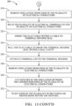
FIG. 2 is a flow chart of a method of assembling an electrical connector according to some embodiments. -
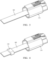
FIG. 3 is an isometric view of an electrical cable of the electrical connector ofFIG. 1 according to some embodiments; -
FIG. 4 is an isometric view of a subassembly of the electrical connector ofFIG. 1 in which the electrical cable ofFIG. 3 inserted within a connector housing according to some embodiments; -
FIG. 5 is an isometric view of a subassembly of the electrical connector ofFIG. 1 in which a cable seal is placed over the electrical cable of the subassembly ofFIG. 4 according to some embodiments; -
FIG. 6 is an isometric view of a subassembly of the electrical connector ofFIG. 1 in which a terminal housing is placed over the electrical cable of the subassembly ofFIG. 5 according to some embodiments; -
FIG. 7 is an isometric view of a subassembly of the electrical connector ofFIG. 1 in which insulation is stripped from the electrical cable of the subassembly ofFIG. 6 to expose the conductors according to some embodiments; -
FIG. 8 is an isometric view of electrical terminal held in a jig according to some embodiments; -
FIG. 9 is an isometric view of the electrical terminal held in the jig ofFIG. 8 being attached to the exposed conductors of the subassembly ofFIG. 6 according to some embodiments; -
FIG. 10 is an isometric view of the exposed conductors ofFIG. 9 folded over the electrical terminals according to some embodiments; -
FIG. 11 is an isometric view of a subassembly of the electrical connector ofFIG. 1 after the electrical cable and electrical terminals have been pulled within the terminal housing of the subassembly ofFIG. 7 in an embodiment of the invention; -
FIG. 12 is an isometric view of a subassembly of the electrical connector ofFIG. 1 after the terminal housing has been pulled within the connector housing of the subassembly ofFIG. 11 in an embodiment of the invention; -
FIG. 13 is an exploded isometric view of the electrical connector ofFIG. 1 showing the subassembly ofFIG. 12 and a terminal cap configured to be attached to the terminal housing in an embodiment of the invention. - A nonlimiting example of an
electrical connector 100 shown inFIG 1 which includes an insulated flexibleflat cable 102 that has a plurality ofelectrical conductors 104, aterminal housing 106 having a plurality ofterminal cavities 108 in which the plurality ofelectrical terminals 110 is disposed, aterminal cap 112 attached to an end of theterminal housing 106, and aconnector housing 114 in which theterminal housing 106 is disposed. - The steps of a
nonlimiting method 200 of assembling theelectrical connector 100 are illustrated inFIGs. 2-12 . InSTEP 202 of themethod 200, theflat cable 102 is provided as shown inFIG 2 . In this example the flat cable includeselectrical conductors 104 having a rectangular cross section joined by a single insulative sheath, such as those in a flat flexible cable (FFC) or flexible printed circuit (FPC). Alternatively, the electrical conductors may have a square, round, or oval cross section, such as in a ribbon cable. In an additional alternative, the flat cable may be replaced with a cable formed of a bundle of individually insulated electrical conductors. - In
STEP 204 of themethod 200, theflat cable 102 is inserted within theconnector housing 114 which has an opening on both ends and defines a connector cavity within as shown inFIG. 3 . - As illustrated in
FIG. 4 , acable seal 116 is placed over theflat cable 102 which corresponds to STEP 222 of themethod 200. Thecable seal 116 may be stretched, or a lubricant may be applied to theflat cable 102 and/orcable seal 116 to facilitate sliding thecable seal 116 over theflat cable 102.STEP 222 may be eliminated if the electrical connector is used in an unsealed application. - In
STEP 206 of themethod 200, theflat cable 102 is inserted within theterminal housing 106 as shown inFIG. 5 . Theterminal housing 106 has the plurality ofterminal cavities 108 and a cable cavity (not shown) extending therethrough. Theterminal housing 106 as shown inFIG. 5 also includes aterminal housing seal 118 that is drawn into a seal cavity (not shown) of theconnector housing 112 by pulling theflat cable 102 perSTEP 224 of themethod 200. Theterminal housing seal 118 may be eliminated if the electrical connector is used in an unsealed application. - As shown by
FIG. 6 ,insulation 120 of theflat cable 102 is removed from ends of theelectrical conductors 104 perSTEP method 200, thereby providing exposedportions 122 of theelectrical conductors 104. In addition,notches 126 are cut into theinsulation 120 between the exposedportions 122 perSTEP 230 of themethod 200. Preferably STEP 220 or 228 is performed prior toSTEP 206 of themethod 200. - In
STEP 214 of themethod 200, theelectrical terminals 110 may be placed into ajig 128 that is configured to hold theelectrical terminals 110 in place as they are attached to the exposedportions 122 of theelectrical conductors 104 as illustrated byFIG. 7 . Theelectrical terminals 110 illustrated here are female tuning fork terminals which are formed from unfolded sheet metal. Alternatively, the terminals may be male blade terminals that are formed from unfolded sheet metal. In an additional alternative, the terminals may be socket or pin terminals formed by any number of metal forming processes. - As shown in
FIG. 8 , the exposedportions 122 of theelectrical conductors 104 are laid over theattachment portion 130 of theelectrical terminals 110 and are attached to theattachment portion 130 perSTEP 208 of themethod 200. This is preferably accomplished by a welding process such as laser welding, ultrasonic welding, braising, or soldering. Alternatively, the exposedportions 122 may be attached to theattachment portions 130 using an electrically conductive adhesive or mechanical crimping process. As illustrated inFIG. 9 , the exposedportions 122 of theelectrical conductors 104 are folded overedges 132 of theattachment portion 130 to increase the contact surface area between theelectrical conductors 104 and theelectrical terminals 110. - In
STEP 210 of themethod 200, theelectrical terminals 110 have been removed from thejig 128 and theflat cable 102 is pulled to draw theelectrical terminals 110 within theterminal cavities 108 in theterminal housing 106 as shown inFIG. 10 . - In
STEP 212 of themethod 200, theflat cable 102 is pulled further to draw theterminal housing seal 118 within a seal cavity (not shown) defined in theterminal housing 106 and pulled even further to draw theterminal housing 106 into theconnector housing 114 as shown inFIG. 11 . - In
STEP 226 of themethod 200, theterminal cap 112, which is configured to retain theelectrical terminals 110 within theterminal cavities 108, is attached to an end of theterminal housing 106. Theterminal cap 112 defines a plurality ofrectangular protrusions 134 shown inFIG. 12 that are formed of an electrically insulative material that are inserted between theelectrical terminals 110. Theterminal housing 106 defines a plurality ofslots 136. Theslots 136 are located between theelectrical terminals 110 and therectangular protrusions 134 are received in theseslots 136. The ends of therectangular protrusions 134 are received in thenotches 126 in theinsulation 120 perSTEP 232 of themethod 200. Theserectangular protrusions 134 electrically insulate theelectrical terminals 110 from one another and thenotches 126 provide a tortuous path between theelectrical terminals 110 thereby increasing the creepage distance needed for high voltage applications, e.g., greater than 48 volts. The protrusions and notches may be eliminated in low voltage applications of theelectrical connector 100, e.g., less than 48 volts. - A flow chart of the
method 200 of assembling theelectrical connector 100 is shown inFIG. 13 . - While this invention has been described in terms of the preferred embodiments thereof, it is not intended to be so limited, but rather only to the extent set forth in the claims that follow. For example, the above-described embodiments (and/or aspects thereof) may be used in combination with each other. In addition, many modifications may be made to configure a particular situation or material to the teachings of the invention without departing from its scope. Dimensions, types of materials, orientations of the various components, and the number and positions of the various components described herein are intended to define parameters of certain embodiments and are by no means limiting and are merely prototypical embodiments.
- Many other embodiments and modifications within the spirit and scope of the claims will be apparent to those of skill in the art upon reviewing the above description. The scope of the invention should, therefore, be determined with reference to the following claims, along with the full scope of equivalents to which such claims are entitled.
- As used herein, 'one or more' includes a function being performed by one element, a function being performed by more than one element, e.g., in a distributed fashion, several functions being performed by one element, several functions being performed by several elements, or any combination of the above.
- It will also be understood that, although the terms first, second, etc. are, in some instances, used herein to describe various elements, these elements should not be limited by these terms. These terms are only used to distinguish one element from another. For example, a first contact could be termed a second contact, and, similarly, a second contact could be termed a first contact, without departing from the scope of the various described embodiments. The first contact and the second contact are both contacts, but they are not the same contact.
- The terminology used in the description of the various described embodiments herein is for the purpose of describing particular embodiments only and is not intended to be limiting. As used in the description of the various described embodiments and the appended claims, the singular forms "a", "an" and "the" are intended to include the plural forms as well, unless the context clearly indicates otherwise. It will also be understood that the term "and/or" as used herein refers to and encompasses all possible combinations of one or more of the associated listed items. It will be further understood that the terms "includes," "including," "comprises," and/or "comprising," when used in this specification, specify the presence of stated features, integers, steps, operations, elements, and/or components, but do not preclude the presence or addition of one or more other features, integers, steps, operations, elements, components, and/or groups thereof.
- As used herein, the term "if' is, optionally, construed to mean "when" or "upon" or "in response to determining" or "in response to detecting," depending on the context. Similarly, the phrase "if it is determined" or "if [a stated condition or event] is detected" is, optionally, construed to mean "upon determining" or "in response to determining" or "upon detecting [the stated condition or event]" or "in response to detecting [the stated condition or event]," depending on the context.
- Additionally, while terms of ordinance or orientation may be used herein these elements should not be limited by these terms. All terms of ordinance or orientation, unless stated otherwise, are used for purposes distinguishing one element from another, and do not denote any particular order, order of operations, direction or orientation unless stated otherwise.
Claims (15)
- A method (200) of assembling an electrical connector (100), comprising:a) providing an insulated flexible flat cable (102) having a plurality of electrical conductors (104);b) inserting the flat cable (102) within a connector housing (114);c) inserting the flat cable (102) within a terminal housing (106);d) attaching a plurality of electrical terminals (110) to the plurality of electrical conductors (104);e) pulling the flat cable (102) to draw the plurality of electrical terminals (110) within a plurality of terminal cavities (108) defined in the terminal housing (106); andf) pulling the flat cable (102) to further draw the terminal housing (106) within the connector housing (114).
- The method (200) according to claim 1, wherein the plurality of electrical terminals (110) are formed of unfolded sheet metal and wherein the method (200) further comprises:
g) attaching the plurality of electrical terminals (110) to the plurality of electrical conductors (104). - The method (200) according to claim 2, wherein the plurality of electrical conductors (104) have a generally rectangular cross section and wherein the method (200) further comprises:h) removing insulation (120) from ends of the plurality of electrical conductors (104), thereby exposing portions of the plurality of electrical conductors (104); andi) folding the plurality of electrical conductors (104) over edges (132) of the plurality of electrical terminals (110).
- The method (200) according to claim 2 or 3, wherein the plurality of electrical terminals (110) are selected from a list consisting of male blade terminals and female tuning fork terminals.
- The method (200) according to any one of the preceding claims, wherein the terminal housing (106) includes a terminal housing (106) to connector housing (114) seal and wherein the method (200) further comprises:j) inserting the flat cable (102) within a cable to terminal housing (106) seal (118); andk) pulling the flat cable (102) to draw the terminal housing (106) seal (118) within a seal cavity defined in the terminal housing (106).
- The method (200) according to claim 5, wherein step j) occurs prior to step c).
- The method (200) according to any one of the preceding claims, wherein the method (200) further comprises:
l) attaching a terminal cap (112) to the terminal housing (106). - The method (200) according to claim 7, wherein the terminal cap (112) defines a plurality of rectangular protrusions (134) located between the plurality of electrical terminals (110) and wherein the terminal housing (106) defines a plurality of slots (136) located between the plurality of electrical terminals (110) in which the plurality of rectangular protrusions (134) are received.
- The method (200) according to claim 8, wherein the method (200) further comprises:m) removing insulation (120) from ends of the plurality of electrical conductors (104), thereby exposing portions of the plurality of electrical conductors (104);n) cutting notches (126) in the insulation (120) between the exposed portions (122) of the plurality of electrical conductors (104); ando) placing ends of the plurality of rectangular protrusions (134) within the notches (126).
- An electrical connector (100) assembly, comprising:an insulated flexible flat cable (102) having a plurality of electrical conductors (104), wherein a portion of each of the plurality of electrical conductors (104) is exposed;a plurality of electrical terminals (110) formed of unfolded sheet metal and attached to the plurality of electrical conductors (104), wherein the plurality of electrical conductors (104) are folded over edges (132) of the exposed portions (122) of the plurality of electrical conductors (104);a terminal housing (106) having a plurality of terminal cavities (108) in which the plurality of electrical terminals (110) is disposed;a terminal cap (112) attached to an end of the terminal housing (106); anda connector housing (114) in which the terminal housing (106) is disposed.
- The electrical connector (100) assembly according to claim 10, wherein the terminal cap (112) defines a plurality of rectangular protrusions (134) located between the plurality of electrical terminals (110) and wherein the terminal housing (106) defines a plurality of slots (136) located between the plurality of electrical terminals (110) in which the plurality of rectangular protrusions (134) are received.
- The electrical connector (100) assembly according to claim 11, wherein the flat cable (102) defines notches (126) in the insulation (120) between the exposed portions (122) of the plurality of electrical conductors (104) and ends of the plurality of rectangular protrusions (134) are disposed within the notches (126).
- The electrical connector (100) assembly according to any one of claims 10 to 12, wherein the plurality of electrical terminals (110) are selected from a list consisting of male blade terminals and female tuning fork terminals.
- An electrical connector (100) produced by a process comprising:a) providing an insulated flexible flat cable (102) having a plurality of electrical conductors (104);b) inserting the flat cable (102) within a connector housing (114);c) inserting the flat cable (102) within a terminal housing (106);d) attaching a plurality of electrical terminals (110) to the plurality of electrical conductors (104);e) pulling the flat cable (102) to draw the plurality of electrical terminals (110) within a plurality of terminal cavities (108) defined in the terminal housing (106); andf) pulling the flat cable (102) to further draw the terminal housing (106) within the connector housing (114).
- The electrical connector (100) according to claim 14, wherein the plurality of electrical terminals (110) are formed of unfolded sheet metal and wherein the process further comprises:
g) attaching the plurality of electrical terminals (110) to the plurality of electrical conductors (104).
Applications Claiming Priority (1)
| Application Number | Priority Date | Filing Date | Title |
|---|---|---|---|
| US18/228,859 US12580356B2 (en) | 2023-08-01 | 2023-08-01 | Method of assembling an electrical connector and an electrical connector |
Publications (2)
| Publication Number | Publication Date |
|---|---|
| EP4503340A2 true EP4503340A2 (en) | 2025-02-05 |
| EP4503340A3 EP4503340A3 (en) | 2025-04-16 |
Family
ID=91958134
Family Applications (1)
| Application Number | Title | Priority Date | Filing Date |
|---|---|---|---|
| EP24189183.7A Pending EP4503340A3 (en) | 2023-08-01 | 2024-07-17 | Electrical connector and a method of assembling an electrical connector |
Country Status (3)
| Country | Link |
|---|---|
| US (1) | US12580356B2 (en) |
| EP (1) | EP4503340A3 (en) |
| CN (1) | CN119447931A (en) |
Family Cites Families (11)
| Publication number | Priority date | Publication date | Assignee | Title |
|---|---|---|---|---|
| US4346959A (en) | 1980-11-10 | 1982-08-31 | General Motors Corporation | Pull-to-seat electrical connector |
| US4895534A (en) | 1987-12-09 | 1990-01-23 | Amp Incorporated | Pull to seat connector |
| US5409405A (en) | 1994-01-18 | 1995-04-25 | General Motors Corporation | Pull-to-seat terminal collar |
| DE112012002847B4 (en) | 2011-07-04 | 2024-06-20 | Yazaki Corporation | Flat cable waterproof connector and waterproof connector assembly for flat cable |
| JP5780433B2 (en) | 2012-09-27 | 2015-09-16 | 住友電装株式会社 | connector |
| EP2779318A1 (en) | 2013-03-11 | 2014-09-17 | Yazaki Europe Ltd | Method for assembling an electrical connector and electrical connector |
| US9356405B1 (en) * | 2015-03-05 | 2016-05-31 | Sony Corporation | Connector tongue element for an electrical connector plug receptacle and a method for producing the same |
| DE102018119844B4 (en) | 2018-07-26 | 2022-10-06 | Auto-Kabel Management Gmbh | Electrical connection and method of making an electrical connection |
| US11411334B2 (en) | 2020-01-03 | 2022-08-09 | Aptiv Technologies Limited | Electrical connector for connecting to flat-wire conductors of a flexible printed circuit |
| JP7557183B2 (en) | 2021-02-05 | 2024-09-27 | 坂東電線株式会社 | Flat conductor cable connection terminal structure |
| US20230007908A1 (en) | 2021-07-08 | 2023-01-12 | Lear Corporation | Electrical terminal with crimped connection to a flat flexible cable |
-
2023
- 2023-08-01 US US18/228,859 patent/US12580356B2/en active Active
-
2024
- 2024-07-17 EP EP24189183.7A patent/EP4503340A3/en active Pending
- 2024-07-31 CN CN202411035570.4A patent/CN119447931A/en active Pending
Also Published As
| Publication number | Publication date |
|---|---|
| US12580356B2 (en) | 2026-03-17 |
| EP4503340A3 (en) | 2025-04-16 |
| CN119447931A (en) | 2025-02-14 |
| US20250047051A1 (en) | 2025-02-06 |
Similar Documents
| Publication | Publication Date | Title |
|---|---|---|
| US10547125B2 (en) | Insulation displacement termination (IDT) for applying multiple electrical wire gauge sizes simultaneously or individually to electrical connectors, stamped and formed strip terminal products, and assembly fixtures thereof | |
| US11784426B2 (en) | Electrical cable assembly, method and apparatus for making same and electrical terminal for same | |
| US20110028034A1 (en) | Hoop material, method of making inner conductor terminal, and coaxial connector | |
| CN110718787A (en) | Flat cable end terminal of automobile wiring harness | |
| JP2836463B2 (en) | Crimp joint connector | |
| EP0312550B1 (en) | Insulation displacement terminal | |
| JPH04337262A (en) | Insulating perforating conductive terminal | |
| US9928939B1 (en) | Device and method for splicing shielded wire cables | |
| US9906003B1 (en) | Device and method for splicing shielded wire cables | |
| US20180294629A1 (en) | Device and method for splicing shielded wire cables | |
| US7228625B1 (en) | Method for attaching an electrical cable to a connector shield | |
| EP1117153B1 (en) | Protecting configuration for flat cables | |
| JP5390792B2 (en) | Connecting member | |
| US12580356B2 (en) | Method of assembling an electrical connector and an electrical connector | |
| EP0021730A1 (en) | Electrical contact capable of receiving a mating contact in either of two mutually perpendicular orientations | |
| US8272901B2 (en) | Crimp contacts and electrical connector assemblies including the same | |
| US4540224A (en) | Grounding clip for use with shielded, jacketed flat cable | |
| JPH088034A (en) | Assembly method of flat cable connector | |
| EP3916919A1 (en) | Conductor connecting structure | |
| US4266843A (en) | Insulation displacing electrical contact and method of making same | |
| EP4322343B1 (en) | Assembly method for a printed circuit board electrical connector | |
| US7001203B2 (en) | Piercing terminal for coaxial cable | |
| EP3982494A2 (en) | Cable harness assembly with a shielded twisted pair cable | |
| JP2003016850A (en) | Flat circuit body and method of manufacturing the same | |
| US20250379394A1 (en) | Integrated High Voltage Isolation Cover |
Legal Events
| Date | Code | Title | Description |
|---|---|---|---|
| PUAI | Public reference made under article 153(3) epc to a published international application that has entered the european phase |
Free format text: ORIGINAL CODE: 0009012 |
|
| STAA | Information on the status of an ep patent application or granted ep patent |
Free format text: STATUS: THE APPLICATION HAS BEEN PUBLISHED |
|
| AK | Designated contracting states |
Kind code of ref document: A2 Designated state(s): AL AT BE BG CH CY CZ DE DK EE ES FI FR GB GR HR HU IE IS IT LI LT LU LV MC ME MK MT NL NO PL PT RO RS SE SI SK SM TR |
|
| PUAL | Search report despatched |
Free format text: ORIGINAL CODE: 0009013 |
|
| AK | Designated contracting states |
Kind code of ref document: A3 Designated state(s): AL AT BE BG CH CY CZ DE DK EE ES FI FR GB GR HR HU IE IS IT LI LT LU LV MC ME MK MT NL NO PL PT RO RS SE SI SK SM TR |
|
| RIC1 | Information provided on ipc code assigned before grant |
Ipc: H01R 13/506 20060101ALN20250312BHEP Ipc: H01R 43/02 20060101ALN20250312BHEP Ipc: H05K 3/00 20060101ALI20250312BHEP Ipc: H01R 43/20 20060101ALI20250312BHEP Ipc: H01R 13/436 20060101ALI20250312BHEP Ipc: H01R 12/65 20110101AFI20250312BHEP |
|
| STAA | Information on the status of an ep patent application or granted ep patent |
Free format text: STATUS: REQUEST FOR EXAMINATION WAS MADE |
|
| 17P | Request for examination filed |
Effective date: 20250515 |