EP4503320A1 - Manufacturing device for secondary battery and manufacturing method for secondary battery - Google Patents
Manufacturing device for secondary battery and manufacturing method for secondary battery Download PDFInfo
- Publication number
- EP4503320A1 EP4503320A1 EP23827361.9A EP23827361A EP4503320A1 EP 4503320 A1 EP4503320 A1 EP 4503320A1 EP 23827361 A EP23827361 A EP 23827361A EP 4503320 A1 EP4503320 A1 EP 4503320A1
- Authority
- EP
- European Patent Office
- Prior art keywords
- mold
- electrode lead
- roller mold
- upper roller
- manufacturing
- Prior art date
- Legal status (The legal status is an assumption and is not a legal conclusion. Google has not performed a legal analysis and makes no representation as to the accuracy of the status listed.)
- Pending
Links
Images





Classifications
-
- H—ELECTRICITY
- H01—ELECTRIC ELEMENTS
- H01M—PROCESSES OR MEANS, e.g. BATTERIES, FOR THE DIRECT CONVERSION OF CHEMICAL ENERGY INTO ELECTRICAL ENERGY
- H01M50/00—Constructional details or processes of manufacture of the non-active parts of electrochemical cells other than fuel cells, e.g. hybrid cells
- H01M50/50—Current conducting connections for cells or batteries
- H01M50/531—Electrode connections inside a battery casing
- H01M50/533—Electrode connections inside a battery casing characterised by the shape of the leads or tabs
-
- H—ELECTRICITY
- H01—ELECTRIC ELEMENTS
- H01M—PROCESSES OR MEANS, e.g. BATTERIES, FOR THE DIRECT CONVERSION OF CHEMICAL ENERGY INTO ELECTRICAL ENERGY
- H01M50/00—Constructional details or processes of manufacture of the non-active parts of electrochemical cells other than fuel cells, e.g. hybrid cells
- H01M50/50—Current conducting connections for cells or batteries
- H01M50/543—Terminals
- H01M50/564—Terminals characterised by their manufacturing process
-
- B—PERFORMING OPERATIONS; TRANSPORTING
- B21—MECHANICAL METAL-WORKING WITHOUT ESSENTIALLY REMOVING MATERIAL; PUNCHING METAL
- B21D—WORKING OR PROCESSING OF SHEET METAL OR METAL TUBES, RODS OR PROFILES WITHOUT ESSENTIALLY REMOVING MATERIAL; PUNCHING METAL
- B21D11/00—Bending not restricted to forms of material mentioned in only one of groups B21D5/00, B21D7/00, B21D9/00; Bending not provided for in groups B21D5/00 - B21D9/00; Twisting
- B21D11/02—Bending by stretching or pulling over a die
-
- H—ELECTRICITY
- H01—ELECTRIC ELEMENTS
- H01M—PROCESSES OR MEANS, e.g. BATTERIES, FOR THE DIRECT CONVERSION OF CHEMICAL ENERGY INTO ELECTRICAL ENERGY
- H01M10/00—Secondary cells; Manufacture thereof
- H01M10/04—Construction or manufacture in general
-
- H—ELECTRICITY
- H01—ELECTRIC ELEMENTS
- H01M—PROCESSES OR MEANS, e.g. BATTERIES, FOR THE DIRECT CONVERSION OF CHEMICAL ENERGY INTO ELECTRICAL ENERGY
- H01M10/00—Secondary cells; Manufacture thereof
- H01M10/04—Construction or manufacture in general
- H01M10/0404—Machines for assembling batteries
-
- H—ELECTRICITY
- H01—ELECTRIC ELEMENTS
- H01M—PROCESSES OR MEANS, e.g. BATTERIES, FOR THE DIRECT CONVERSION OF CHEMICAL ENERGY INTO ELECTRICAL ENERGY
- H01M50/00—Constructional details or processes of manufacture of the non-active parts of electrochemical cells other than fuel cells, e.g. hybrid cells
- H01M50/50—Current conducting connections for cells or batteries
- H01M50/531—Electrode connections inside a battery casing
-
- H—ELECTRICITY
- H01—ELECTRIC ELEMENTS
- H01M—PROCESSES OR MEANS, e.g. BATTERIES, FOR THE DIRECT CONVERSION OF CHEMICAL ENERGY INTO ELECTRICAL ENERGY
- H01M50/00—Constructional details or processes of manufacture of the non-active parts of electrochemical cells other than fuel cells, e.g. hybrid cells
- H01M50/50—Current conducting connections for cells or batteries
- H01M50/531—Electrode connections inside a battery casing
- H01M50/534—Electrode connections inside a battery casing characterised by the material of the leads or tabs
-
- H—ELECTRICITY
- H01—ELECTRIC ELEMENTS
- H01M—PROCESSES OR MEANS, e.g. BATTERIES, FOR THE DIRECT CONVERSION OF CHEMICAL ENERGY INTO ELECTRICAL ENERGY
- H01M50/00—Constructional details or processes of manufacture of the non-active parts of electrochemical cells other than fuel cells, e.g. hybrid cells
- H01M50/50—Current conducting connections for cells or batteries
- H01M50/531—Electrode connections inside a battery casing
- H01M50/536—Electrode connections inside a battery casing characterised by the method of fixing the leads to the electrodes, e.g. by welding
-
- H—ELECTRICITY
- H01—ELECTRIC ELEMENTS
- H01M—PROCESSES OR MEANS, e.g. BATTERIES, FOR THE DIRECT CONVERSION OF CHEMICAL ENERGY INTO ELECTRICAL ENERGY
- H01M50/00—Constructional details or processes of manufacture of the non-active parts of electrochemical cells other than fuel cells, e.g. hybrid cells
- H01M50/50—Current conducting connections for cells or batteries
- H01M50/531—Electrode connections inside a battery casing
- H01M50/54—Connection of several leads or tabs of plate-like electrode stacks, e.g. electrode pole straps or bridges
-
- H—ELECTRICITY
- H01—ELECTRIC ELEMENTS
- H01M—PROCESSES OR MEANS, e.g. BATTERIES, FOR THE DIRECT CONVERSION OF CHEMICAL ENERGY INTO ELECTRICAL ENERGY
- H01M50/00—Constructional details or processes of manufacture of the non-active parts of electrochemical cells other than fuel cells, e.g. hybrid cells
- H01M50/50—Current conducting connections for cells or batteries
- H01M50/543—Terminals
- H01M50/552—Terminals characterised by their shape
-
- H—ELECTRICITY
- H01—ELECTRIC ELEMENTS
- H01M—PROCESSES OR MEANS, e.g. BATTERIES, FOR THE DIRECT CONVERSION OF CHEMICAL ENERGY INTO ELECTRICAL ENERGY
- H01M50/00—Constructional details or processes of manufacture of the non-active parts of electrochemical cells other than fuel cells, e.g. hybrid cells
- H01M50/50—Current conducting connections for cells or batteries
- H01M50/543—Terminals
- H01M50/552—Terminals characterised by their shape
- H01M50/553—Terminals adapted for prismatic, pouch or rectangular cells
-
- Y—GENERAL TAGGING OF NEW TECHNOLOGICAL DEVELOPMENTS; GENERAL TAGGING OF CROSS-SECTIONAL TECHNOLOGIES SPANNING OVER SEVERAL SECTIONS OF THE IPC; TECHNICAL SUBJECTS COVERED BY FORMER USPC CROSS-REFERENCE ART COLLECTIONS [XRACs] AND DIGESTS
- Y02—TECHNOLOGIES OR APPLICATIONS FOR MITIGATION OR ADAPTATION AGAINST CLIMATE CHANGE
- Y02E—REDUCTION OF GREENHOUSE GAS [GHG] EMISSIONS, RELATED TO ENERGY GENERATION, TRANSMISSION OR DISTRIBUTION
- Y02E60/00—Enabling technologies; Technologies with a potential or indirect contribution to GHG emissions mitigation
- Y02E60/10—Energy storage using batteries
-
- Y—GENERAL TAGGING OF NEW TECHNOLOGICAL DEVELOPMENTS; GENERAL TAGGING OF CROSS-SECTIONAL TECHNOLOGIES SPANNING OVER SEVERAL SECTIONS OF THE IPC; TECHNICAL SUBJECTS COVERED BY FORMER USPC CROSS-REFERENCE ART COLLECTIONS [XRACs] AND DIGESTS
- Y02—TECHNOLOGIES OR APPLICATIONS FOR MITIGATION OR ADAPTATION AGAINST CLIMATE CHANGE
- Y02P—CLIMATE CHANGE MITIGATION TECHNOLOGIES IN THE PRODUCTION OR PROCESSING OF GOODS
- Y02P70/00—Climate change mitigation technologies in the production process for final industrial or consumer products
- Y02P70/50—Manufacturing or production processes characterised by the final manufactured product
Definitions
- the present invention relates to a manufacturing device of a secondary battery and a manufacturing method of a secondary battery, and more particularly, to a manufacturing device of a secondary battery and a manufacturing method of a secondary battery capable of preventing disconnection by reducing tensile stress applied to a joint region of an electrode lead and an electrode tab.
- secondary batteries are a representative example of electrochemical devices that use such electrochemical energy, and the use range thereof has gradually expanded.
- the lithium secondary batteries are manufactured by applying a positive electrode or negative electrode active material, a binder, and a conductive material in the form of slurry to a current collector and performing drying to form an electrode mixture layer to manufacture a positive electrode and a negative electrode, placing a separator between the positive electrode and the negative electrode, laminating them to obtain an electrode assembly, and installing the electrode assembly together with an electrolyte in a battery case. Electrode tabs extending from each cell of the electrode assembly built into the battery case are gathered together and welded to be connected to an electrode lead. The electrode tabs may be electrically connected to an external device by the electrode leads.
- FIG. 1 and 2 are diagrams illustrating a manufacturing device of a secondary battery according to the related art.
- FIG. 1 is a diagram illustrating a state before bending of an electrode lead in a manufacturing device of a secondary battery according to the related art
- FIG. 2 is a diagram illustrating a state after bending of an electrode lead in a manufacturing device of a secondary battery according to the related art.
- an electrode assembly 1 is formed by stacking a plurality of positive electrodes and negative electrodes with a separator interposed therebetween, and the electrode assembly 1 is housed in a battery case 2, thereby manufacturing a secondary battery.
- An electrode tabs 3 connected to each electrode included in the electrode assembly 1 are gathered together, welded, and connected to an electrode lead 4 as shown in the drawing.
- a lead film 5 surrounding the electrode lead 4 may be located on the electrode lead 4 to increase sealing force with the battery case 2.
- the electrode lead 4 may be electrically connected to an external device and may be formed to have various shapes appropriately depending on a connection environment.
- a process of bending the electrode lead 4 into an appropriate shape is required.
- upper and lower molds 30 and 40 having the shape of the electrode lead 4 to be obtained are prepared, and in a state in which a joint portion of the battery case 2 and the electrode lead 4 is fixed by an upper fixing mold 10 and a lower fixing mold 20, the upper and lower molds 30 and 40 are coupled to press the electrode lead 4.
- the present invention provides a manufacturing device of a secondary battery and a manufacturing method of a secondary battery capable of preventing disconnection in a joint portion of an electrode tab and an electrode lead due to tensile force occurring in a process of forming the electrode lead and capable of forming electrode leads having various shapes using a single manufacturing device.
- the lower roller mold and the upper roller mold may each rotate and move independently.
- the manufacturing device may further include: a lower support mold disposed between the lower fixing mold and the lower roller mold and supporting a lower surface of the electrode lead.
- the upper roller mold may include: a first upper roller mold and a second upper roller mold sequentially arranged in a direction toward the outer end of the electrode lead, and the lower roller mold includes the first lower roller mold and the second lower roller mold sequentially arranged in the direction toward the outer end of the electrode lead.
- the first lower roller mold, the first upper roller mold, the second lower roller mold, and the second upper roller mold may be sequentially arranged in the direction toward the outer end of the electrode lead.
- the upper roller mold may include a first upper roller mold and a second upper roller mold sequentially arranged in a direction toward the outer end of the electrode lead
- the lower roller mold may include the first lower roller mold and the second lower roller mold sequentially arranged in the direction toward the outer end of the electrode lead.
- the first lower roller mold, the first upper roller mold, the second lower roller mold, and the second upper roller mold may be sequentially arranged in the direction toward the outer end of the electrode lead.
- the forming of the second bent portion may include: forming a primary curved portion having a shape corresponding to a lower portion of the first upper roller mold and a secondary curved portion having a shape corresponding to an upper portion of the second lower roller mold by simultaneously lowering the first upper roller mold and the second upper roller mold.
- the forming of the second bent portion may include: forming a primary curved portion having a shape corresponding to a lower portion of the first upper roller mold by lowering the first upper roller mold; and forming a secondary curved portion having a shape corresponding to an upper portion of the second lower roller mold by lowering the second upper roller mold.
- the forming of the second bent portion may include: lowering the second upper roller mold to bring the second upper roller mold into contact with the electrode lead, and forming the primary curved portion having a shape corresponding to a lower portion of the first upper roller mold and a secondary curved portion having a shape corresponding to an upper portion of the second lower roller mold by lowering the first upper roller mold.
- tensile force during a process of forming the electrode lead may be minimized, thereby preventing disconnection from occurring at the joint portion of the electrode tab and the electrode lead.
- the manufacturing device of a secondary battery and the manufacturing method of a secondary battery capable of forming electrode leads having various shapes may be provided using a single manufacturing device without manufacturing additional molds, etc.
- FIGS. 3 and 4 a manufacturing device of a secondary battery according to an exemplary embodiment of the present invention will be described with reference to FIGS. 3 and 4 .
- a secondary battery includes an electrode assembly 1 housed in a battery case 2 and includes an electrode lead 4 drawn out of the battery case 2 for electrical connection to the outside.
- the electrode assembly 1 is a power generating device that can be charged and discharged and has a structure in which a positive electrode and a negative electrode are alternately stacked with a separator therebetween.
- Electrode tabs 3 are formed extending from the ends of electrodes included in the electrode assembly 1, respectively. The electrode tabs 3 may be gathered into one point and welded, and the gathered electrode tabs 3 and the electrode lead 4 may be joined by means, such as welding.
- a lead film 5 may be located to surround the electrode lead 4 in at least one of upper and lower portions of the electrode lead 4. The lead film 5 may improve sealing properties of a sealing portion of the battery case 2 and the electrode lead 4, while preventing a short-circuit from occurring in the electrode lead 4 during heat fusion.
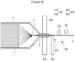
- the manufacturing device of a secondary battery is a device for forming, especially, a portion of the aforementioned electrode lead 4 protruding outwardly from the battery case 2, and includes an upper fixing mold 100 and a lower fixing mold 200 for fixing the electrode lead 4 and an upper roller mold 300, a lower roller mold 400, and a lower support mold 500 directly contacting the electrode lead 4 to form the shape of the electrode lead 4.
- the upper fixing mold 100 and the lower fixing mold 200 are used to fix the electrode lead 4 during a molding process.
- the upper fixing mold 100 and the lower fixing mold 200 support a portion in which the electrode lead 4 is fixed to the battery case 2 to fix the electrode lead 4.
- the upper fixing mold 100 and the lower fixing mold 200 are formed to press the portion in which the battery case 2 and the electrode lead 4 overlap each other, while contacting the portion above and below.
- the lower support mold 500 is disposed to be adjacent to the lower fixing mold 200 and spaced apart from the lower fixing mold 200 toward an outer end of the electrode lead 4.
- the lower support mold 500 is in contact with a starting point of the electrode lead 4 in which molding begins, and has a shape corresponding to a first bent portion 41 of the electrode lead 4. That is, the first bent portion 41 may be formed at a position corresponding to the lower support mold 500 by pressing the upper roller mold 300 and the lower roller mold 400, which will be described below.
- the upper roller mold 300 and the lower roller mold 400 are arranged to be spaced apart from the upper fixing mold 100 and the lower fixing mold 200, respectively, toward the outer end of the electrode lead 4, and the electrode lead 4 is located between the upper roller mold 300 and the lower roller molds 400.
- the lower roller mold 400 is spaced apart from the lower fixing mold 200 with the lower support mold 500 interposed therebetween.
- a plurality of upper roller molds 300 and lower roller molds 400 may be provided, and in the present exemplary embodiment, an example in which two upper roller molds 300 and two lower roller molds 400 are provided is described, but without being limited thereto, the number and position of the upper roller mold 300 and lower roller mold 400 may be adjusted in various ways.
- the upper roller mold 300 includes a first upper roller mold 310 and a second upper roller mold 320
- the lower roller mold 400 includes a first lower roller mold 410 and a second lower roller mold 420.
- these roller molds are arranged in the order of a first lower roller mold 410, a first upper roller mold 310, a second lower roller mold 420, and a second upper roller mold 320 in a direction from the lower support mold 500 toward the outer end of the electrode lead 4.
- the upper roller molds 300 may be lowered toward the electrode lead 4 and continue to be lowered, while placed between the lower roller molds 400, to press the electrode lead 4, thereby molding the electrode lead 4.
- the upper roller mold 300 and the lower roller mold 400 are configured to rotate independently.
- these roller molds 300 and 400 rotate, thereby minimizing frictional force with the electrode lead 4 and consequently reducing tensile force applied to the electrode lead 4.
- tensile force is reduced thereby, it is possible to prevent disconnection in a joint portion A of the electrode tab 3 and the electrode lead 4, which has a relatively weak bonding strength.
- disconnection occurred frequently due to the tensile force applied to the corresponding portion during molding of the electrode lead 4.
- frictional contact and tensile force may be minimized to prevent such disconnection by using roller molds 300 and 400, instead of the conventional stamp type mold.
- positions of the upper roller mold 300 and lower roller mold 400 may change independently. Therefore, it is possible to mold the electrode lead 4 of various shapes without replacing the mold by adjusting vertical and horizontal positions of the roller molds 300 and 400 to correspond to a required shape depending on the product.
- a bending angle of the first bent portion 41 may be determined by a vertical position and pressing force of the first upper roller mold 310.
- the second bent portion 42 may have two curved portions, that is, a primary curved portion 42a and a secondary curved portion 42b.
- the shape of the primary curved portion 42a may correspond to a lower surface of the first upper roller mold 310, and the secondary curved portion 42b may correspond to an upper surface of the second lower roller mold 420.
- the degree of bending, that is, a depth or width, of the primary curved portion 42a and the secondary curved portion 42b may be changed by adjusting a lowering height of the upper roller mold 300 and a distance between the upper roller mold 300 and the lower roller mold 400.
- the size and number of roller molds 300 and 400 are not limited to the present exemplary embodiment and may be appropriately determined depending on a required shape of the electrode lead 4, etc.
- the occurrence of disconnection may be prevented by minimizing tensile force applied to the electrode lead 4 and the electrode tab 3 during bending of the electrode lead 4, and in addition, since the electrode lead 4 having various shapes may be molded even with the single manufacturing device, without replacing the mold, manufacturing costs may be reduced.
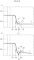
- FIG. 5 is a diagram illustrating a manufacturing method of a secondary battery according to an exemplary embodiment of the present invention
- FIGS. 6 and 7 are diagrams illustrating a manufacturing method of a secondary battery according to other exemplary embodiments of the present invention.
- the electrode lead 4 is fixed between the upper fixing mold 100 and the lower fixing mold 200, and the electrode lead 4 is bent in a portion in which the lower support mold 500 supports the electrode lead 4, to form the first bent portion 41.
- the electrode lead 4 may be bent downwardly, that is, in a direction toward the lower support mold 500, while being supported by the lower support mold 500, and accordingly, the first bent portion 41 may have a shape corresponding to an upper surface of the lower support mold 500.
- the second bent portion 42 is formed using the upper roller mold 300 and the lower roller mold 400.
- the primary curved portion 42a and the secondary curved portion 42b included in the second bent portion 42 are formed by simultaneously lowering the first and second upper roller molds 310 and 320 included in the upper roller mold 300. That is, the primary curved portion 42a corresponding to the shape of the lower surface of the first upper roller mold 310 and the secondary curved portion 42b corresponding to the shape of the upper surface of the second lower roller mold 420 may be formed by pressing the electrode lead 4 by simultaneously lowering the first and second upper roller molds 310 and 320.
- a manufacturing method of a secondary battery according to another exemplary embodiment of the present invention is different from the manufacturing method according to one exemplary embodiment in that the first upper roller mold 310 is first lowered and the second upper roller mold 320 is then lowered, rather than both the first and second upper roller molds 310 and 320 are lowered at the same time. That is, after the electrode lead 4 comes into contact with the first lower roller mold 410, the first upper roller mold 310, and the second lower roller mold 420 by lowering the first upper roller mold 310, the second upper roller mold 320 is lowered to press the electrode lead 4, thereby forming the primary curved portion 42a and the secondary curved portion 42b.
- a manufacturing method of a secondary battery according to another exemplary embodiment of the present invention is different from the manufacturing method of one exemplary embodiment in that the second upper roller mold 320 is first lowered and the first upper roller mold 310 is then lowered, rather than both the first and second upper roller molds 310 and 320 are lowered at the same time. That is, after the electrode lead 4 comes into contact with the second upper roller mole 320 by lowering the second upper roller mold 320, and subsequently, the first upper roller mold 310 may be lowered to press the electrode lead 4, thereby forming the primary curved portion 42a and the secondary curved portion 42b.
- the electrode lead 4 having a desired shape may be manufactured by lowering and moving each roller mold, especially, the upper roller molds, in various orders.
- Example 1 the maximum value of tensile force applied to the joint portion A of the electrode tab 3 and the electrode lead 4 when the upper roller mold 300 was moved by about 12 mm according to the manufacturing method of FIG. 5 was measured.
- Example 2 the maximum value of tensile force was measured in the same manner as that of the manufacturing method of FIG. 6
- Example 3 the maximum value of tensile force was measured in the same manner as that of Example 1 according to the manufacturing method of FIG. 7 .
- Table 1 The results are shown in Table 1 below. [Table 1] Maximum tensile force (N) Example 1 419.3 Example 2 295.8 Example 3 586.9 Comparative Example 665.4
Landscapes
- Chemical & Material Sciences (AREA)
- Chemical Kinetics & Catalysis (AREA)
- Electrochemistry (AREA)
- General Chemical & Material Sciences (AREA)
- Engineering & Computer Science (AREA)
- Manufacturing & Machinery (AREA)
- Mechanical Engineering (AREA)
- Secondary Cells (AREA)
- Connection Of Batteries Or Terminals (AREA)
Abstract
Description
- This application claims benefit of priority to
Korean Patent Application No. 1 0-2022-0074849 filed on June 20, 2022 - The present invention relates to a manufacturing device of a secondary battery and a manufacturing method of a secondary battery, and more particularly, to a manufacturing device of a secondary battery and a manufacturing method of a secondary battery capable of preventing disconnection by reducing tensile stress applied to a joint region of an electrode lead and an electrode tab.
- Due to the rapid increase in the use of fossil fuels, demand for the use of alternative and clean energy has increased, and as portion of this, the most actively researched fields are power generation and storage using electrochemistry.
- Currently, secondary batteries are a representative example of electrochemical devices that use such electrochemical energy, and the use range thereof has gradually expanded.
- Recently, technological development of and growing demand for portable devices, such as portable computers, portable phones, and cameras, have led to a rapid increase in demand for secondary batteries as an energy source, and in the midway, lithium secondary batteries exhibiting high energy density and operating potential and having a long cycle life and a low self-discharge rate have actively been researched, commercialized, and widely used.
- In addition, in line with the growing interest in environmental issues, research has been conducted on electric vehicles and hybrid electric vehicles that may replace vehicles using fossil fuels, such as gasoline vehicles and diesel vehicles, which are one of the main causes of air pollution. Although nickel hydride metal secondary batteries have been mainly used as a power source for such electric vehicles and hybrid electric vehicles, research on the use of lithium secondary batteries with high energy density and discharge voltage has been actively conducted, and some are in a commercialization stage.
- The lithium secondary batteries are manufactured by applying a positive electrode or negative electrode active material, a binder, and a conductive material in the form of slurry to a current collector and performing drying to form an electrode mixture layer to manufacture a positive electrode and a negative electrode, placing a separator between the positive electrode and the negative electrode, laminating them to obtain an electrode assembly, and installing the electrode assembly together with an electrolyte in a battery case. Electrode tabs extending from each cell of the electrode assembly built into the battery case are gathered together and welded to be connected to an electrode lead. The electrode tabs may be electrically connected to an external device by the electrode leads.
-
FIG. 1 and2 are diagrams illustrating a manufacturing device of a secondary battery according to the related art. -
FIG. 1 is a diagram illustrating a state before bending of an electrode lead in a manufacturing device of a secondary battery according to the related art, andFIG. 2 is a diagram illustrating a state after bending of an electrode lead in a manufacturing device of a secondary battery according to the related art. - Referring to
FIGS. 1 and2 , an electrode assembly 1 is formed by stacking a plurality of positive electrodes and negative electrodes with a separator interposed therebetween, and the electrode assembly 1 is housed in abattery case 2, thereby manufacturing a secondary battery. An electrode tabs 3 connected to each electrode included in the electrode assembly 1 are gathered together, welded, and connected to anelectrode lead 4 as shown in the drawing. A lead film 5 surrounding theelectrode lead 4 may be located on theelectrode lead 4 to increase sealing force with thebattery case 2. - The
electrode lead 4 may be electrically connected to an external device and may be formed to have various shapes appropriately depending on a connection environment. In order to form theelectrode lead 4, a process of bending theelectrode lead 4 into an appropriate shape is required. For such bending, as shown inFIGS. 1 and2 , upper andlower molds electrode lead 4 to be obtained are prepared, and in a state in which a joint portion of thebattery case 2 and theelectrode lead 4 is fixed by anupper fixing mold 10 and alower fixing mold 20, the upper andlower molds electrode lead 4. In this case, due to force pressing theelectrode lead 4, strong tensile force may be especially applied to a joint portion A of theelectrode lead 4 and the electrode tab 3, thereby causing the joint portion A of the electrode tab 3 and theelectrode lead 4 to be disconnected. In addition, according to the related art, since theelectrode lead 4 is formed to have only one shape using the upper andlower molds electrode lead 4 in various shapes, and therefore, there is a problem in that an individual mold corresponding to the shape of theelectrode lead 4 is required depending on the product type. - The present invention provides a manufacturing device of a secondary battery and a manufacturing method of a secondary battery capable of preventing disconnection in a joint portion of an electrode tab and an electrode lead due to tensile force occurring in a process of forming the electrode lead and capable of forming electrode leads having various shapes using a single manufacturing device.
- However, the problems to be solved by the exemplary embodiments of the present invention are not limited to the aforementioned problems and may be expanded in various ways within the scope of the technical idea included in the present invention.
- According to an exemplary embodiment of the present invention, a manufacturing device of a secondary battery, as a manufacturing device of a secondary battery including a plurality of electrodes and separators stacked alternately, electrode tabs provided at ends of the plurality of electrodes, and an electrode lead coupled to the electrode tabs, includes an upper fixing mold and a lower fixing mold fixing the electrode lead interposed therebetween, a plurality of lower roller molds arranged to be spaced apart from the lower fixing mold toward an outer end of the electrode lead, and a plurality of upper roller molds arranged to be spaced apart from the upper fixing mold toward the outer end of the electrode lead.
- The lower roller mold and the upper roller mold may each rotate and move independently.
- The manufacturing device may further include: a lower support mold disposed between the lower fixing mold and the lower roller mold and supporting a lower surface of the electrode lead.
- The upper roller mold may include: a first upper roller mold and a second upper roller mold sequentially arranged in a direction toward the outer end of the electrode lead, and the lower roller mold includes the first lower roller mold and the second lower roller mold sequentially arranged in the direction toward the outer end of the electrode lead.
- The first lower roller mold, the first upper roller mold, the second lower roller mold, and the second upper roller mold may be sequentially arranged in the direction toward the outer end of the electrode lead.
- According to another exemplary embodiment of the present invention, a manufacturing method of a secondary battery, as a manufacturing method of a secondary battery including a plurality of electrodes and separators stacked alternately, electrode tabs provided at ends of the plurality of electrodes, and an electrode lead coupled to the electrode tabs, includes fixing the electrode lead between an upper fixing mold and a lower fixing mold, forming a first bent portion by bending the electrode lead in a direction toward a lower support mold, while supporting a lower portion of the electrode lead with the lower support mold disposed to be adjacent to the lower fixing mold, and forming a second bent portion using a plurality of lower roller molds spaced apart from the lower fixing mold toward an outer end of the electrode lead and a plurality of upper roller molds spaced apart from the upper fixing mold toward the outer end of the electrode lead.
- The upper roller mold may include a first upper roller mold and a second upper roller mold sequentially arranged in a direction toward the outer end of the electrode lead, and the lower roller mold may include the first lower roller mold and the second lower roller mold sequentially arranged in the direction toward the outer end of the electrode lead.
- The first lower roller mold, the first upper roller mold, the second lower roller mold, and the second upper roller mold may be sequentially arranged in the direction toward the outer end of the electrode lead.
- The forming of the second bent portion may include: forming a primary curved portion having a shape corresponding to a lower portion of the first upper roller mold and a secondary curved portion having a shape corresponding to an upper portion of the second lower roller mold by simultaneously lowering the first upper roller mold and the second upper roller mold.
- The forming of the second bent portion may include: forming a primary curved portion having a shape corresponding to a lower portion of the first upper roller mold by lowering the first upper roller mold; and forming a secondary curved portion having a shape corresponding to an upper portion of the second lower roller mold by lowering the second upper roller mold.
- The forming of the second bent portion may include: lowering the second upper roller mold to bring the second upper roller mold into contact with the electrode lead, and forming the primary curved portion having a shape corresponding to a lower portion of the first upper roller mold and a secondary curved portion having a shape corresponding to an upper portion of the second lower roller mold by lowering the first upper roller mold.
- According to exemplary embodiments of the present invention, tensile force during a process of forming the electrode lead may be minimized, thereby preventing disconnection from occurring at the joint portion of the electrode tab and the electrode lead. In addition, the manufacturing device of a secondary battery and the manufacturing method of a secondary battery capable of forming electrode leads having various shapes may be provided using a single manufacturing device without manufacturing additional molds, etc.
- The effects of the present invention are not limited to the effects mentioned above, and other effects not mentioned will be clearly understood by those skilled in the art from the description of the claims.
-
-
FIG. 1 is a diagram illustrating a state before bending of an electrode lead in a manufacturing device of a secondary battery according to the related art. -
FIG. 2 is a diagram illustrating a state after bending of an electrode lead in a manufacturing device of a secondary battery according to the related art. -
FIG. 3 is a diagram illustrating a state before bending of an electrode lead in a manufacturing device of a secondary battery according to an exemplary embodiment of the present invention. -
FIG. 4 is a diagram illustrating a state after bending of an electrode lead in the manufacturing device of a secondary battery ofFIG. 3 . -
FIG. 5 is a diagram illustrating a manufacturing method of a secondary battery according to an exemplary embodiment of the present invention. -
FIGS. 6 and7 are diagrams illustrating a manufacturing method of a secondary battery according to other exemplary embodiments of the present invention. - Hereinafter, exemplary embodiments of the present invention will be described in detail with reference to the accompanying drawings to allow those skilled in the art to practice the present invention. The present invention may be implemented in various different forms and is not limited to the examples as described herein.
- In the drawings, parts irrelevant to the description are omitted to clearly describe the present invention, and like reference numerals denote like elements throughout the specification.
- The size and thickness of each component shown in the drawings may be arbitrarily shown for convenience of explanation, and therefore, the present invention is not necessarily limited to the shown exemplary embodiments in the drawings. In the drawings, the thickness of layers, films, panels, regions, etc., are exaggerated for clarity. Also, in the drawings, the thickness of partial layers and regions may be exaggerated for convenience of explanation.
- It will be understood that when an element, such as a layer, film, region, or substrate is referred to as being "on" another element, it may be directly on the other element or intervening elements may also be present. In contrast, when an element is referred to as being "directly on" another element, there are no intervening elements present. Further, when an element is "above" or "on" the reference portion, it may mean that the element is located above or below the reference portion, and it may not necessarily mean that the element is "above" or "on" toward an opposite direction of gravity.
- In addition, unless explicitly described to the contrary, the word "comprise", and variations, such as "comprises" or "comprising", will be understood to imply the inclusion of stated elements but not the exclusion of any other elements.
- Hereinafter, a manufacturing device of a secondary battery according to an exemplary embodiment of the present invention will be described with reference to
FIGS. 3 and4 . - A secondary battery includes an electrode assembly 1 housed in a
battery case 2 and includes anelectrode lead 4 drawn out of thebattery case 2 for electrical connection to the outside. The electrode assembly 1 is a power generating device that can be charged and discharged and has a structure in which a positive electrode and a negative electrode are alternately stacked with a separator therebetween. Electrode tabs 3 are formed extending from the ends of electrodes included in the electrode assembly 1, respectively. The electrode tabs 3 may be gathered into one point and welded, and the gathered electrode tabs 3 and theelectrode lead 4 may be joined by means, such as welding. - One end of the
electrode lead 4 is electrically connected to the electrode tab 3 and extends via a sealing portion of thebattery case 2, and the opposite end of theelectrode lead 4 protrudes out of thebattery case 2. A lead film 5 may be located to surround theelectrode lead 4 in at least one of upper and lower portions of theelectrode lead 4. The lead film 5 may improve sealing properties of a sealing portion of thebattery case 2 and theelectrode lead 4, while preventing a short-circuit from occurring in theelectrode lead 4 during heat fusion. - Referring to
FIGS. 3 and4 , the manufacturing device of a secondary battery according to an exemplary embodiment of the present invention is a device for forming, especially, a portion of theaforementioned electrode lead 4 protruding outwardly from thebattery case 2, and includes anupper fixing mold 100 and alower fixing mold 200 for fixing theelectrode lead 4 and anupper roller mold 300, alower roller mold 400, and alower support mold 500 directly contacting theelectrode lead 4 to form the shape of theelectrode lead 4. - The
upper fixing mold 100 and thelower fixing mold 200 are used to fix theelectrode lead 4 during a molding process. In particular, the upper fixingmold 100 and thelower fixing mold 200 support a portion in which theelectrode lead 4 is fixed to thebattery case 2 to fix theelectrode lead 4. To this end, as shown inFIG. 3 , the upper fixingmold 100 and thelower fixing mold 200 are formed to press the portion in which thebattery case 2 and theelectrode lead 4 overlap each other, while contacting the portion above and below. - The
lower support mold 500 is disposed to be adjacent to thelower fixing mold 200 and spaced apart from thelower fixing mold 200 toward an outer end of theelectrode lead 4. Thelower support mold 500 is in contact with a starting point of theelectrode lead 4 in which molding begins, and has a shape corresponding to a firstbent portion 41 of theelectrode lead 4. That is, the firstbent portion 41 may be formed at a position corresponding to thelower support mold 500 by pressing theupper roller mold 300 and thelower roller mold 400, which will be described below. - The
upper roller mold 300 and thelower roller mold 400 are arranged to be spaced apart from the upper fixingmold 100 and thelower fixing mold 200, respectively, toward the outer end of theelectrode lead 4, and theelectrode lead 4 is located between theupper roller mold 300 and thelower roller molds 400. In particular, thelower roller mold 400 is spaced apart from thelower fixing mold 200 with thelower support mold 500 interposed therebetween. - A plurality of
upper roller molds 300 andlower roller molds 400 may be provided, and in the present exemplary embodiment, an example in which twoupper roller molds 300 and twolower roller molds 400 are provided is described, but without being limited thereto, the number and position of theupper roller mold 300 andlower roller mold 400 may be adjusted in various ways. - The
upper roller mold 300 includes a firstupper roller mold 310 and a secondupper roller mold 320, and thelower roller mold 400 includes a firstlower roller mold 410 and a secondlower roller mold 420. As shown inFIGS. 3 and4 , these roller molds are arranged in the order of a firstlower roller mold 410, a firstupper roller mold 310, a secondlower roller mold 420, and a secondupper roller mold 320 in a direction from thelower support mold 500 toward the outer end of theelectrode lead 4. In this state, theupper roller molds 300 may be lowered toward theelectrode lead 4 and continue to be lowered, while placed between thelower roller molds 400, to press theelectrode lead 4, thereby molding theelectrode lead 4. - At this time, the
upper roller mold 300 and thelower roller mold 400 are configured to rotate independently. When pressing theelectrode lead 4, theseroller molds electrode lead 4 and consequently reducing tensile force applied to theelectrode lead 4. In particular, when tensile force is reduced thereby, it is possible to prevent disconnection in a joint portion A of the electrode tab 3 and theelectrode lead 4, which has a relatively weak bonding strength. In the joint portion A of the electrode tab 3 and theelectrode lead 4, disconnection occurred frequently due to the tensile force applied to the corresponding portion during molding of theelectrode lead 4. However, as in the present exemplary embodiment, frictional contact and tensile force may be minimized to prevent such disconnection by usingroller molds - In addition, positions of the
upper roller mold 300 andlower roller mold 400 may change independently. Therefore, it is possible to mold theelectrode lead 4 of various shapes without replacing the mold by adjusting vertical and horizontal positions of theroller molds bent portion 41 and the secondbent portion 42, a bending angle of the firstbent portion 41 may be determined by a vertical position and pressing force of the firstupper roller mold 310. In addition, the secondbent portion 42 may have two curved portions, that is, a primarycurved portion 42a and a secondarycurved portion 42b. The shape of the primarycurved portion 42a may correspond to a lower surface of the firstupper roller mold 310, and the secondarycurved portion 42b may correspond to an upper surface of the secondlower roller mold 420. The degree of bending, that is, a depth or width, of the primarycurved portion 42a and the secondarycurved portion 42b may be changed by adjusting a lowering height of theupper roller mold 300 and a distance between theupper roller mold 300 and thelower roller mold 400. In addition, the size and number ofroller molds electrode lead 4, etc. - According to the manufacturing device of a secondary battery according to an exemplary embodiment of the present invention, the occurrence of disconnection may be prevented by minimizing tensile force applied to the
electrode lead 4 and the electrode tab 3 during bending of theelectrode lead 4, and in addition, since theelectrode lead 4 having various shapes may be molded even with the single manufacturing device, without replacing the mold, manufacturing costs may be reduced. - Hereinafter, as a manufacturing method using a manufacturing device of a secondary battery described above, a manufacturing method of a secondary battery according to one exemplary embodiment and another exemplary embodiment of the present invention will be described.
-
FIG. 5 is a diagram illustrating a manufacturing method of a secondary battery according to an exemplary embodiment of the present invention, andFIGS. 6 and7 are diagrams illustrating a manufacturing method of a secondary battery according to other exemplary embodiments of the present invention. - Referring to
FIG. 5 , in the manufacturing method of a secondary battery according to an exemplary embodiment of the present invention, first, theelectrode lead 4 is fixed between the upper fixingmold 100 and thelower fixing mold 200, and theelectrode lead 4 is bent in a portion in which thelower support mold 500 supports theelectrode lead 4, to form the firstbent portion 41. At this time, theelectrode lead 4 may be bent downwardly, that is, in a direction toward thelower support mold 500, while being supported by thelower support mold 500, and accordingly, the firstbent portion 41 may have a shape corresponding to an upper surface of thelower support mold 500. - Next, the second
bent portion 42 is formed using theupper roller mold 300 and thelower roller mold 400. In the present exemplary embodiment, as shown inFIG. 5 , the primarycurved portion 42a and the secondarycurved portion 42b included in the secondbent portion 42 are formed by simultaneously lowering the first and secondupper roller molds upper roller mold 300. That is, the primarycurved portion 42a corresponding to the shape of the lower surface of the firstupper roller mold 310 and the secondarycurved portion 42b corresponding to the shape of the upper surface of the secondlower roller mold 420 may be formed by pressing theelectrode lead 4 by simultaneously lowering the first and secondupper roller molds - Referring to
FIG. 6 , a manufacturing method of a secondary battery according to another exemplary embodiment of the present invention is different from the manufacturing method according to one exemplary embodiment in that the firstupper roller mold 310 is first lowered and the secondupper roller mold 320 is then lowered, rather than both the first and secondupper roller molds electrode lead 4 comes into contact with the firstlower roller mold 410, the firstupper roller mold 310, and the secondlower roller mold 420 by lowering the firstupper roller mold 310, the secondupper roller mold 320 is lowered to press theelectrode lead 4, thereby forming the primarycurved portion 42a and the secondarycurved portion 42b. - Referring to
FIG. 7 , a manufacturing method of a secondary battery according to another exemplary embodiment of the present invention is different from the manufacturing method of one exemplary embodiment in that the secondupper roller mold 320 is first lowered and the firstupper roller mold 310 is then lowered, rather than both the first and secondupper roller molds electrode lead 4 comes into contact with the secondupper roller mole 320 by lowering the secondupper roller mold 320, and subsequently, the firstupper roller mold 310 may be lowered to press theelectrode lead 4, thereby forming the primarycurved portion 42a and the secondarycurved portion 42b. - In this manner, in the manufacturing method of forming the
electrode lead 4 using the manufacturing device of a secondary battery according to an exemplary embodiment of the present invention, theelectrode lead 4 having a desired shape may be manufactured by lowering and moving each roller mold, especially, the upper roller molds, in various orders. - Hereinafter, tensile force occurring in the manufacturing method of a secondary battery according to the exemplary embodiments of the present invention and a manufacturing method of a secondary battery according to a comparative example will be measured and the results will be described.
- In Example 1, the maximum value of tensile force applied to the joint portion A of the electrode tab 3 and the
electrode lead 4 when theupper roller mold 300 was moved by about 12 mm according to the manufacturing method ofFIG. 5 was measured. In Example 2, the maximum value of tensile force was measured in the same manner as that of the manufacturing method ofFIG. 6 , and in Example 3, the maximum value of tensile force was measured in the same manner as that of Example 1 according to the manufacturing method ofFIG. 7 . Meanwhile, in the comparative example, the maximum value of tensile force applied to the joint portion A of the electrode tab 3 and theelectrode lead 4 by moving theupper mold 30 by about 12 mm, which is the same as that of Example 1, was measured using the molds ofFIGS. 1 and2 . The results are shown in Table 1 below.[Table 1] Maximum tensile force (N) Example 1 419.3 Example 2 295.8 Example 3 586.9 Comparative Example 665.4 - As shown in Table 1, it was confirmed that in the examples of the present invention in which the
electrode lead 4 was molded using theroller molds electrode lead 4 may be prevented during the process of molding theelectrode lead 4. - While the present invention has been described in connection with exemplary embodiments, it is to be understood that the invention is not limited to the disclosed exemplary embodiments, but, on the contrary, is intended to cover various modifications and equivalent arrangements included within the spirit and scope of the appended claims.
-
- 3: electrode tab
- 4: electrode lead
- 100: upper fixing mold
- 200: lower fixing mold
- 300: upper roller mold
- 310: first upper roller mold
- 320: second upper roller mold
- 400: lower roller mold
- 410: first lower roller mold
- 420: second lower roller mold
- 500: lower support mold
Claims (11)
- A manufacturing device of a secondary battery including a plurality of electrodes and separators stacked alternately, electrode tabs provided at ends of the plurality of electrodes, and an electrode lead coupled to the electrode tabs, the manufacturing device comprising:an upper fixing mold and a lower fixing mold fixing the electrode lead interposed therebetween;a plurality of lower roller molds arranged to be spaced apart from the lower fixing mold toward an outer end of the electrode lead; anda plurality of upper roller molds arranged to be spaced apart from the upper fixing mold toward the outer end of the electrode lead.
- The manufacturing device of claim 1, wherein:
the lower roller mold and the upper roller mold each rotate and move independently. - The manufacturing device of claim 1, further comprising:
a lower support mold disposed between the lower fixing mold and the lower roller mold and supporting a lower surface of the electrode lead. - The manufacturing device of claim 3, wherein:
the upper roller mold includes a first upper roller mold and a second upper roller mold sequentially arranged in a direction toward the outer end of the electrode lead, and the lower roller mold includes the first lower roller mold and the second lower roller mold sequentially arranged in the direction toward the outer end of the electrode lead. - The manufacturing device of claim 4, wherein:
the first lower roller mold, the first upper roller mold, the second lower roller mold, and the second upper roller mold are sequentially arranged in the direction toward the outer end of the electrode lead. - A manufacturing method of a secondary battery including a plurality of electrodes and separators stacked alternately, electrode tabs provided at ends of the plurality of electrodes, and an electrode lead coupled to the electrode tabs, the manufacturing method comprising:fixing the electrode lead between an upper fixing mold and a lower fixing mold;forming a first bent portion by bending the electrode lead in a direction toward a lower support mold, while supporting a lower portion of the electrode lead with the lower support mold disposed to be adjacent to the lower fixing mold; andforming a second bent portion using a plurality of lower roller molds spaced apart from the lower fixing mold toward an outer end of the electrode lead and a plurality of upper roller molds spaced apart from the upper fixing mold toward the outer end of the electrode lead.
- The manufacturing method of claim 6, wherein:
the upper roller mold includes a first upper roller mold and a second upper roller mold sequentially arranged in a direction toward the outer end of the electrode lead, and the lower roller mold includes the first lower roller mold and the second lower roller mold sequentially arranged in the direction toward the outer end of the electrode lead. - The manufacturing method of claim 7, wherein:
the first lower roller mold, the first upper roller mold, the second lower roller mold, and the second upper roller mold are sequentially arranged in the direction toward the outer end of the electrode lead. - The manufacturing method of claim 8, wherein:the forming of the second bent portion includesforming a primary curved portion having a shape corresponding to a lower portion of the first upper roller mold and a secondary curved portion having a shape corresponding to an upper portion of the second lower roller mold by simultaneously lowering the first upper roller mold and the second upper roller mold.
- The manufacturing method of claim 8, wherein:
the forming of the second bent portion includes:forming a primary curved portion having a shape corresponding to a lower portion of the first upper roller mold by lowering the first upper roller mold; andforming a secondary curved portion having a shape corresponding to an upper portion of the second lower roller mold by lowering the second upper roller mold. - The manufacturing method of claim 8, wherein:
the forming of the second bent portion includes:lowering the second upper roller mold to bring the second upper roller mold into contact with the electrode lead, andforming the primary curved portion having a shape corresponding to a lower portion of the first upper roller mold and a secondary curved portion having a shape corresponding to an upper portion of the second lower roller mold by lowering the first upper roller mold.
Applications Claiming Priority (2)
| Application Number | Priority Date | Filing Date | Title |
|---|---|---|---|
| KR1020220074849A KR20230173971A (en) | 2022-06-20 | 2022-06-20 | Manufacturing device of secondary battery and manufacturing method of secondary battery |
| PCT/KR2023/005776 WO2023249241A1 (en) | 2022-06-20 | 2023-04-27 | Manufacturing device for secondary battery and manufacturing method for secondary battery |
Publications (2)
| Publication Number | Publication Date |
|---|---|
| EP4503320A1 true EP4503320A1 (en) | 2025-02-05 |
| EP4503320A4 EP4503320A4 (en) | 2025-12-17 |
Family
ID=89378335
Family Applications (1)
| Application Number | Title | Priority Date | Filing Date |
|---|---|---|---|
| EP23827361.9A Pending EP4503320A4 (en) | 2022-06-20 | 2023-04-27 | SECONDARY BATTERY MANUFACTURING DEVICE AND SECONDARY BATTERY MANUFACTURING METHOD |
Country Status (6)
| Country | Link |
|---|---|
| US (1) | US20250293411A1 (en) |
| EP (1) | EP4503320A4 (en) |
| JP (1) | JP7845764B2 (en) |
| KR (1) | KR20230173971A (en) |
| CN (1) | CN119096417A (en) |
| WO (1) | WO2023249241A1 (en) |
Families Citing this family (1)
| Publication number | Priority date | Publication date | Assignee | Title |
|---|---|---|---|---|
| KR20260034416A (en) * | 2024-09-04 | 2026-03-11 | 삼성에스디아이 주식회사 | Secondary battery, device for manufacturing same and method for manufacturing same |
Family Cites Families (14)
| Publication number | Priority date | Publication date | Assignee | Title |
|---|---|---|---|---|
| JPH0682772B2 (en) * | 1988-12-29 | 1994-10-19 | 日本電気株式会社 | Lead forming method for surface mount device |
| US5074139A (en) * | 1991-03-04 | 1991-12-24 | Motorola, Inc. | Roll forming of semiconductor component leadframes |
| JPH06224351A (en) * | 1993-01-26 | 1994-08-12 | Oki Electric Ind Co Ltd | Lead processing apparatus for semiconductor device and processing method thereof |
| JPH08215763A (en) * | 1995-02-20 | 1996-08-27 | Nisshin Steel Co Ltd | Preforming device for producing broad material having good shape free from corrugating |
| JPH0945360A (en) * | 1995-07-31 | 1997-02-14 | Fuji Photo Film Co Ltd | Manufacturing method of cylindrical battery |
| KR101062267B1 (en) * | 2008-11-19 | 2011-09-05 | 주식회사 금창 | Multi-axis Bending Machine for Steel Tube Bending |
| CN101958165A (en) * | 2009-07-20 | 2011-01-26 | 德阳市德东电工机械制造有限公司 | Mobile deformer of tubular stranding machine |
| JP5830953B2 (en) * | 2010-11-17 | 2015-12-09 | ソニー株式会社 | Secondary battery, battery unit and battery module |
| JP2013171618A (en) * | 2012-02-17 | 2013-09-02 | Sanyo Electric Co Ltd | Laminate outer body battery |
| JP2013225388A (en) * | 2012-04-20 | 2013-10-31 | Sony Corp | Battery and electrolyte, and battery pack, electronic apparatus, electric vehicle, power storage device and electric power system |
| CN207521469U (en) * | 2017-11-09 | 2018-06-22 | 宁德新能源科技有限公司 | For the folding lug mechanism of lithium ion battery |
| KR102517098B1 (en) * | 2018-05-29 | 2023-04-03 | 주식회사 엘지에너지솔루션 | Battery module |
| KR102739779B1 (en) * | 2019-02-28 | 2024-12-09 | 주식회사 엘지에너지솔루션 | Electrode assembly manufacturing method and electrode assembly manufacturing device |
| KR102751962B1 (en) * | 2020-01-15 | 2025-01-10 | 주식회사 엘지에너지솔루션 | The Apparatus And The Method For Folding Electrode Tab |
-
2022
- 2022-06-20 KR KR1020220074849A patent/KR20230173971A/en active Pending
-
2023
- 2023-04-27 CN CN202380036098.3A patent/CN119096417A/en active Pending
- 2023-04-27 JP JP2024560905A patent/JP7845764B2/en active Active
- 2023-04-27 US US18/861,182 patent/US20250293411A1/en active Pending
- 2023-04-27 WO PCT/KR2023/005776 patent/WO2023249241A1/en not_active Ceased
- 2023-04-27 EP EP23827361.9A patent/EP4503320A4/en active Pending
Also Published As
| Publication number | Publication date |
|---|---|
| JP2025513910A (en) | 2025-04-30 |
| US20250293411A1 (en) | 2025-09-18 |
| CN119096417A (en) | 2024-12-06 |
| WO2023249241A1 (en) | 2023-12-28 |
| JP7845764B2 (en) | 2026-04-14 |
| KR20230173971A (en) | 2023-12-27 |
| EP4503320A4 (en) | 2025-12-17 |
Similar Documents
| Publication | Publication Date | Title |
|---|---|---|
| US11031646B2 (en) | Cylindrical battery cell manufacturing device comprising secondary crimping mold | |
| US11923564B2 (en) | Method for producing battery module | |
| KR101117687B1 (en) | Battery Pack | |
| KR102089264B1 (en) | Device for Charge and Discharge of Secondary Battery | |
| CN101411005B (en) | Secondary battery with improved safety | |
| US11139523B2 (en) | Battery cell frame and battery module comprising same | |
| KR101572832B1 (en) | Stepped Electrode Group Stack | |
| US12418187B2 (en) | Jig for charging and discharging battery cell | |
| EP4432455A1 (en) | Electrode tab welding apparatus, electrode tab welding method, and secondary battery | |
| KR20160079220A (en) | Battery Pack Prepared Using Electrical Connecting Member for Battery Cell with Contact Bending Part | |
| US20250293411A1 (en) | Device for forming electrode lead of secondary battery and method of forming electrode lead | |
| US20260045650A1 (en) | Manufacturing Device of Secondary Battery and Manufacturing Method of Secondary Battery | |
| US10615621B2 (en) | Apparatus for charging and discharging battery cell comprising insulation mask | |
| JP5625119B2 (en) | Conductive connection structure of secondary battery cell | |
| KR20120123851A (en) | Electrode assembly including anode and cathod electrode more than 2 and electrochemical device using the same | |
| US20240014433A1 (en) | Method of Manufacturing an Electrode Assembly and Manufacturing Apparatus Thereof | |
| KR102930968B1 (en) | The Secondary Battery And The Battery Module | |
| KR20170045515A (en) | Electrode Assembly Comprising Anode Having Extra Part for Improving Capacity and Battery Cell Comprising the Same | |
| EP4708419A1 (en) | Device for manufacturing secondary battery, and method of manufacturing secondary battery | |
| JP2025541489A (en) | Tape forming jig, jelly roll taping device including the same, and jelly roll taping method | |
| US20110286148A1 (en) | Electrochemical device and method for manufacturing the same | |
| KR20220021225A (en) | Secondary battery with enhanced cooling efficiency and secondary battery module comprising the same |
Legal Events
| Date | Code | Title | Description |
|---|---|---|---|
| STAA | Information on the status of an ep patent application or granted ep patent |
Free format text: STATUS: THE INTERNATIONAL PUBLICATION HAS BEEN MADE |
|
| PUAI | Public reference made under article 153(3) epc to a published international application that has entered the european phase |
Free format text: ORIGINAL CODE: 0009012 |
|
| STAA | Information on the status of an ep patent application or granted ep patent |
Free format text: STATUS: REQUEST FOR EXAMINATION WAS MADE |
|
| 17P | Request for examination filed |
Effective date: 20241031 |
|
| AK | Designated contracting states |
Kind code of ref document: A1 Designated state(s): AL AT BE BG CH CY CZ DE DK EE ES FI FR GB GR HR HU IE IS IT LI LT LU LV MC ME MK MT NL NO PL PT RO RS SE SI SK SM TR |
|
| DAV | Request for validation of the european patent (deleted) | ||
| DAX | Request for extension of the european patent (deleted) | ||
| REG | Reference to a national code |
Ref country code: DE Ref legal event code: R079 Free format text: PREVIOUS MAIN CLASS: H01M0050533000 Ipc: H01M0010040000 |
|
| A4 | Supplementary search report drawn up and despatched |
Effective date: 20251114 |
|
| RIC1 | Information provided on ipc code assigned before grant |
Ipc: H01M 10/04 20060101AFI20251110BHEP Ipc: H01M 50/533 20210101ALI20251110BHEP Ipc: H01M 50/531 20210101ALI20251110BHEP Ipc: H01M 50/534 20210101ALI20251110BHEP Ipc: H01M 50/536 20210101ALI20251110BHEP Ipc: H01M 50/54 20210101ALI20251110BHEP Ipc: H01M 50/553 20210101ALI20251110BHEP |