EP4503298A1 - End cap assembly, battery cell, and electric device - Google Patents
End cap assembly, battery cell, and electric device Download PDFInfo
- Publication number
- EP4503298A1 EP4503298A1 EP22948273.2A EP22948273A EP4503298A1 EP 4503298 A1 EP4503298 A1 EP 4503298A1 EP 22948273 A EP22948273 A EP 22948273A EP 4503298 A1 EP4503298 A1 EP 4503298A1
- Authority
- EP
- European Patent Office
- Prior art keywords
- end cover
- battery cell
- exhaust channel
- hole
- insulating component
- Prior art date
- Legal status (The legal status is an assumption and is not a legal conclusion. Google has not performed a legal analysis and makes no representation as to the accuracy of the status listed.)
- Pending
Links
Images




Classifications
-
- H—ELECTRICITY
- H01—ELECTRIC ELEMENTS
- H01M—PROCESSES OR MEANS, e.g. BATTERIES, FOR THE DIRECT CONVERSION OF CHEMICAL ENERGY INTO ELECTRICAL ENERGY
- H01M50/00—Constructional details or processes of manufacture of the non-active parts of electrochemical cells other than fuel cells, e.g. hybrid cells
- H01M50/30—Arrangements for facilitating escape of gases
- H01M50/35—Gas exhaust passages comprising elongated, tortuous or labyrinth-shaped exhaust passages
- H01M50/367—Internal gas exhaust passages forming part of the battery cover or case; Double cover vent systems
-
- H—ELECTRICITY
- H01—ELECTRIC ELEMENTS
- H01M—PROCESSES OR MEANS, e.g. BATTERIES, FOR THE DIRECT CONVERSION OF CHEMICAL ENERGY INTO ELECTRICAL ENERGY
- H01M50/00—Constructional details or processes of manufacture of the non-active parts of electrochemical cells other than fuel cells, e.g. hybrid cells
- H01M50/10—Primary casings; Jackets or wrappings
- H01M50/147—Lids or covers
- H01M50/148—Lids or covers characterised by their shape
- H01M50/15—Lids or covers characterised by their shape for prismatic or rectangular cells
-
- H—ELECTRICITY
- H01—ELECTRIC ELEMENTS
- H01M—PROCESSES OR MEANS, e.g. BATTERIES, FOR THE DIRECT CONVERSION OF CHEMICAL ENERGY INTO ELECTRICAL ENERGY
- H01M50/00—Constructional details or processes of manufacture of the non-active parts of electrochemical cells other than fuel cells, e.g. hybrid cells
- H01M50/30—Arrangements for facilitating escape of gases
-
- H—ELECTRICITY
- H01—ELECTRIC ELEMENTS
- H01M—PROCESSES OR MEANS, e.g. BATTERIES, FOR THE DIRECT CONVERSION OF CHEMICAL ENERGY INTO ELECTRICAL ENERGY
- H01M50/00—Constructional details or processes of manufacture of the non-active parts of electrochemical cells other than fuel cells, e.g. hybrid cells
- H01M50/30—Arrangements for facilitating escape of gases
- H01M50/342—Non-re-sealable arrangements
- H01M50/3425—Non-re-sealable arrangements in the form of rupturable membranes or weakened parts, e.g. pierced with the aid of a sharp member
-
- H—ELECTRICITY
- H01—ELECTRIC ELEMENTS
- H01M—PROCESSES OR MEANS, e.g. BATTERIES, FOR THE DIRECT CONVERSION OF CHEMICAL ENERGY INTO ELECTRICAL ENERGY
- H01M50/00—Constructional details or processes of manufacture of the non-active parts of electrochemical cells other than fuel cells, e.g. hybrid cells
- H01M50/30—Arrangements for facilitating escape of gases
- H01M50/35—Gas exhaust passages comprising elongated, tortuous or labyrinth-shaped exhaust passages
- H01M50/358—External gas exhaust passages located on the battery cover or case
-
- H—ELECTRICITY
- H01—ELECTRIC ELEMENTS
- H01M—PROCESSES OR MEANS, e.g. BATTERIES, FOR THE DIRECT CONVERSION OF CHEMICAL ENERGY INTO ELECTRICAL ENERGY
- H01M50/00—Constructional details or processes of manufacture of the non-active parts of electrochemical cells other than fuel cells, e.g. hybrid cells
- H01M50/30—Arrangements for facilitating escape of gases
- H01M50/394—Gas-pervious parts or elements
-
- H—ELECTRICITY
- H01—ELECTRIC ELEMENTS
- H01M—PROCESSES OR MEANS, e.g. BATTERIES, FOR THE DIRECT CONVERSION OF CHEMICAL ENERGY INTO ELECTRICAL ENERGY
- H01M2220/00—Batteries for particular applications
- H01M2220/20—Batteries in motive systems, e.g. vehicle, ship, plane
-
- Y—GENERAL TAGGING OF NEW TECHNOLOGICAL DEVELOPMENTS; GENERAL TAGGING OF CROSS-SECTIONAL TECHNOLOGIES SPANNING OVER SEVERAL SECTIONS OF THE IPC; TECHNICAL SUBJECTS COVERED BY FORMER USPC CROSS-REFERENCE ART COLLECTIONS [XRACs] AND DIGESTS
- Y02—TECHNOLOGIES OR APPLICATIONS FOR MITIGATION OR ADAPTATION AGAINST CLIMATE CHANGE
- Y02E—REDUCTION OF GREENHOUSE GAS [GHG] EMISSIONS, RELATED TO ENERGY GENERATION, TRANSMISSION OR DISTRIBUTION
- Y02E60/00—Enabling technologies; Technologies with a potential or indirect contribution to GHG emissions mitigation
- Y02E60/10—Energy storage using batteries
Definitions
- the present application relates to the technical field of batteries, and more particularly to an end cover assembly of a battery cell and an electrical device.
- a battery is composed of a plurality of battery cells.
- Each battery cell includes a case, an end cover assembly, and an electrode assembly located in the case.
- the end cover assembly is configured to cover the electrode assembly in the case.
- Battery cells need to have certain exhaust performance to avoid safety issues caused by imbalance of internal and external pressures. For this reason, it is an urgent problem to be solved to improve the exhaust efficiency and reliability of battery cells.
- the present application provides an end cover assembly of a battery cell and an electrical device that can improve the exhaust efficiency and reliability of the battery cell.
- an end cover assembly for a battery cell includes: an end cover, an exhaust mechanism being provided on the end cover; and an insulating component provided on the side of the end cover close to the interior of the battery cell.
- An exhaust channel is provided between the insulating component and the end cover to communicate the exhaust mechanism with the interior of the battery cell.
- the end cover assembly of the battery cell includes an end cover and an insulating component.
- the insulating component is provided on the side of the end cover close to the interior of the battery cell.
- An exhaust mechanism is provided on the end cover assembly and an exhaust channel is provided between the insulating component and the end cover to communicate the exhaust mechanism with the interior of the battery cell.
- the exhaust channel includes a groove provided on the surface of the insulating component facing the end cover.
- one end of the exhaust channel is in communication with the exhaust mechanism, and the other end of the exhaust channel is in communication with an edge of the insulating component.
- the area of the insulating component is smaller than that of the end cover.
- the exhaust channel includes a groove provided on the surface of the end cover facing the interior of the battery cell.
- one end of the exhaust channel is in communication with the exhaust mechanism, and the other end of the exhaust channel is in communication with the position on the end cover corresponding to the edge of the insulating component.
- the area of the insulating component is smaller than that of the end cover.
- the exhaust mechanism includes a pressure relief component to relieve the pressure inside the battery cell when thermal runaway occurs in the battery cell.
- the exhaust channel is configured to communicate the pressure relief component with the interior of the battery cell.
- the air inside the battery cell can reach the pressure relief component through the exhaust channel between the insulating component and the end cover, thereby relieving the pressure through the pressure relief component.
- the exhaust channel facilitates circulation of the air inside the battery cell to the pressure relief component, thereby improving the safety of the battery cell.
- a ventilating structure is provided on the end cover.
- the ventilating structure includes a ventilating hole and a ventilating film covering the ventilating hole, and the exhaust channel is configured to communicate the ventilating structure with the interior of the battery cell.
- the ventilating hole and the ventilating film on the exhaust mechanism are configured to balance the air pressure of the battery cell and the outside world.
- the exhaust channel between the insulating component and the end cover facilitates circulation of the air inside the battery cell to the ventilating film, improving the ventilation efficiency of the battery cell.
- a step is provided on the surface of the end cover close to the interior of the battery cell, a support sheet is accommodated in the step, and at least one through hole is provided in the support sheet.
- the ventilating film is located between the support sheet and the end cover and covers the at least one through hole, and the exhaust channel is configured to communicate the at least one through hole with the interior of the battery cell.
- the ratio of the cross-sectional area of the exhaust channel to the total area of the at least one through hole is greater than or equal to 0.1% and less than or equal to 40%; preferably, greater than or equal to 0.2% and less than or equal to 20%; further preferably, greater than or equal to 0.5% and less than or equal to 15%.
- the ratio of the cross-sectional area of the exhaust channel to the total area of the at least one through hole is within the appropriate range as described above, the exhaust capability of the ventilating film can match with that of the at least one through hole.
- the total area of at least one through hole is so small that the air passing through the ventilating film cannot be discharged from the at least one through hole in time, and it is also avoided that the total area of the at least one through hole is so large that the reliability of fixing and supporting of the ventilating film by the support sheet is compromised.
- the exhaust mechanism further includes a pressure relief component, a first through hole is provided in the insulating component at a position corresponding to the pressure relief component, and the exhaust channel is configured to communicate the ventilating structure with the first through hole.
- a second through hole is provided in the insulating component at a position corresponding to the ventilating structure, and the exhaust channel is configured to communicate the ventilating structure with the second through hole.
- a baffle is provided between the second through hole and the metal component in the battery cell to isolate the end cover from the metal component.
- the baffle can prevent the metal wire on the end cover from overlapping with the metal component in the battery cell and avoid short circuits, improving the safety of the battery cell.
- a connecting member is provided between the baffle and the insulating component to fix the baffle to the insulating component.
- An exhaust gap is formed between the baffle and the insulating component.
- the width of the exhaust channel is greater than or equal to 0.5 mm and less than or equal to 4 mm; and/or the depth of the exhaust channel is greater than or equal to 0.1 mm and less than or equal to 0.6 mm.
- the exhaust channel can obtain better exhaust capability without having a major impact on the structure of the end cover and the insulating component, ensuring the structural stability of the end cover assembly.
- a battery cell including: an electrode assembly; a case to accommodate the electrode assembly; and an end cover assembly described in the first aspect or any implementation of the first aspect, the end cover assembly being configured to close the electrode assembly within the case.
- an electrical device including a plurality of battery cells described in the first aspect, the battery cells being configured to supply electric energy to the electrical device.
- the same reference numerals indicate the same parts and, for the sake of brevity, the detailed description of the same parts is omitted in the different embodiments. It should be understood that the dimensions such as the thickness, length, and width of various components in the embodiments of the present application shown in the drawings, as well as the dimensions such as the overall thickness, length, and width of the integrated device are illustrative only and shall not constitute any limitation on the present application.
- the battery cell may include a lithium-ion battery, a lithium-sulfur battery, a sodium-lithium-ion battery, a sodium-ion battery, a magnesium-ion battery, or the like, which is not limited in embodiments of the present application.
- the battery cell may be cylindrical, flat, cuboid, or in other shapes, which is also not limited in embodiments of the present application.
- the battery cells are generally divided into three types according to packaging manners: cylindrical battery cells, prismatic battery cells, and pouch cells, which is also not limited in embodiments of the present application.
- the battery mentioned in the embodiments of the present application refers to a single physical module including one or more battery cells to provide a higher voltage and capacity.
- the battery mentioned in the present application may include a battery module, a battery pack, or the like.
- the battery generally includes a box for encapsulating one or more battery cells. The box can prevent liquids or other foreign matters from affecting the charging or discharging of the battery cells.
- a battery cell relies on the gap between its end cover and the insulating component located on the side of the end cover close to the interior of the battery cell for air exchange.
- liquid sealing will occur, affecting the discharge performance of the battery cell, which may easily cause safety problems due to imbalance of internal and external pressures of the battery cell.
- embodiments of the present application provide an end cover assembly including an end cover and an insulating component.
- An exhaust channel is provided between the insulating component and the end cover to communicate the exhaust mechanism with the interior of the battery cell. Therefore, the space between the end cover and the insulating component is increased, and the probability of liquid sealing is reduced, which is beneficial to circulation of the air inside the battery cell to the exhaust mechanism, thereby improving the exhaust efficiency and reliability of the battery cell.
- the electrical devices may be, but not limited to, a vehicle, a mobile phone, a portable device, a laptop computer, a ship, a spacecraft, an electric toy, an electric tool, and the like.
- the vehicle may be a fuel vehicle, an air vehicle or a new energy vehicle.
- the new energy vehicle may be an all-electric vehicle, a hybrid electric vehicle, an extended-range electric vehicle, or the like.
- the spacecraft includes airplanes, rockets, space shuttles, spaceships, and the like.
- the electric toy includes fixed or mobile electric toys, such as game consoles, electric car toys, electric ship toys and electric aircraft toys.
- the electric tool includes metal cutting electric tools, grinding electric tools, assembly electric tools and railway electric tools, such as electric drills, electric grinders, electric wrenches, electric screwdrivers, electric hammers, impact drills, concrete vibrators and electric planers.
- electric drills such as electric drills, electric grinders, electric wrenches, electric screwdrivers, electric hammers, impact drills, concrete vibrators and electric planers.
- Embodiments of the present application do not impose special limitations on the above electrical device.
- the electrical device being a vehicle as an example.
- a schematic structural diagram of a vehicle 1 according to an embodiment of the present application is shown.
- the vehicle 1 may be a fuel vehicle, a gas vehicle, or a new energy vehicle, and the new energy vehicle may be an all-electric vehicle, a hybrid vehicle, an extended range electric vehicle, or the like.
- the interior of the vehicle 1 can be provided with a motor 40, a controller 30, and a battery 10, and the controller 30 is used for controlling the battery 10 to power the motor 40.
- the battery 10 may be arranged at the bottom or the head or the tail of the vehicle 1.
- the battery 10 may be configured to supply power to the vehicle 1.
- the battery 10 may be used as an operating power source of the vehicle 1, which is used for a circuit system of the vehicle 1, for example, for operation power requirements of the vehicle 1 during starting, navigation and running.
- the battery 10 can serve not only as an operating power supply for the vehicle 1, but also as a driving power source for the vehicle 1, so as to replace or partially replace fuel or natural air to provide driving power for the vehicle 1.
- the battery 10 may also be called a battery pack.
- Fig. 2 shows a schematic structural view of a battery 10 according to an embodiment of the present application.
- the battery 10 may include a plurality of battery cells 20.
- the battery 10 may further include a box 11, the box 11 is of a hollow structure inside, and the plurality of battery cells 20 are accommodated in the box 11.
- Fig. 2 shows a possible implementation of the box 11 according to an embodiment of the present application.
- the box 11 may include two parts, which are referred to here as a first box portion 111 and a second box portion 112 respectively, and the first box portion 111 and the second box portion 112 are snap-fitted together.
- the shapes of the first box portion 111 and the second box portion 112 may be determined according to the combined shape of the plurality of battery cells 20, and at least one of the first box portion 111 and the second box portion 112 has an opening.
- both the first box portion 111 and the second box portion 112 may be hollow cuboids and each has only one surface being an opening surface, the opening of the first box portion 111 and the opening of the second box portion 112 are disposed opposite to each other, and the first box portion 111 and the second box portion 112 are snap-fitted together to form the box 11 having an enclosed cavity.
- first box portion 111 and the second box portion 112 may be a hollow cuboid with an opening, and the other one may be of a plate shape to cover the opening.
- the second box portion 112 is a hollow cuboid and has only one surface being an opening surface
- the first box portion 111 is of a plate shape. Then the opening of the second box portion 112 is covered by the first box portion 111 to form the box 11 having an enclosed cavity for accommodating the plurality of battery cells 20.
- the plurality of battery cells 20 are combined in parallel, in series or in a hybrid pattern, and then placed in the box 11 formed by snap-fitting the first box portion 111 to the second box portion 112.
- the battery 10 may also include other structures, which will not be described here.
- the battery 10 may further include a busbar component configured to realize electrical connection between the plurality of battery cells 20, such as parallel connection, series connection or hybrid connection.
- the busbar component may realize electrical connection between the battery cells 20 by connecting electrode terminals of the battery cells 20.
- the busbar component may be fixed to the electrode terminals of the battery cells 20 by welding. Electric energy from the plurality of battery cells 20 may be further led out via an electrically conductive mechanism through the box 11.
- the number of battery cells 20 in the battery 10 may be set to any value.
- the plurality of battery cells 20 may be connected in series, parallel or hybrid pattern to achieve larger capacity or power, where the term hybrid pattern means mixture of series and parallel connections. Since each battery 10 may include a large number of battery cells 20, in order to facilitate installation, the battery cells 20 may be arranged in groups, and each group of battery cells 20 forms a battery module 200.
- the number of battery cells 20 included in the battery module 200 is not limited and may be set according to the demand. That is, the plurality of battery cells 20 may directly form a battery 10, or may form battery modules first, and then the battery modules form a battery 10.
- the battery cell 20 includes one or more electrode assemblies 22, a case 211 and an end cover 212.
- the case 211 and the end cover 212 form a housing or battery case 21.
- the wall of the case 211 and the end cover 212 are both called the wall of the battery cell 20.
- the wall of the case 211 includes a bottom wall and four side walls.
- the shape of the case 211 is determined according to the combined shape of one or more electrode assemblies 22.
- the case 211 may be a hollow cuboid, cube, or cylinder, and one of the surfaces of the case 211 has an opening to facilitate placing the one or more electrode assemblies 22 in the case 211.
- one of the planes of the case 211 is an opening surface, that is, this plane has no walls so that the inside and outside of the case 211 are in communication with each other.
- the end surface of the case 211 is an opening surface, that is, this end surface does not have a wall so that the inside and outside of the case 211 are in communication with each other.
- the end cover 212 covers the opening and is connected with the case 211 to form an enclosed cavity in which the electrode assemblies 22 are placed.
- the case 211 is filled with electrolyte, such as electrolyte solution.
- an insulating component 214 is further provided on the side of the end cover 212 facing the electrode assembly 22.
- the insulating component 214 may also be called lower plastic.
- the battery cell 20 may further include two electrode terminals 214, which may be provided on the end cover 212.
- the end cover 212 is generally in the shape of a flat plate, and the two electrode terminals 214 are fixed to the flat plate surface of the end cover 212.
- the two electrode terminals 214 are a positive electrode terminal 214a and a negative electrode terminal 214b respectively.
- Each of the electrode terminals 214 is provided with a corresponding connecting member 23, which may alternatively be referred to as a current collecting member 23, located between the end cover 212 and the electrode assembly 22 for electrically connecting the electrode assembly 22 and the electrode terminal 214.
- each electrode assembly 22 has a first tab 221a and a second tab 222a.
- the first tab 221a and the second tab 222a have opposite polarities.
- the first tab 221a is a positive electrode tab
- the second tab 222a is a negative electrode tab.
- the first tab 221a of one or more electrode assemblies 22 is connected to one electrode terminal via one connecting member 23, and the second tab 222a of the one or more electrode assemblies 22 is connected to the other electrode terminal via the other connecting member 23.
- the positive electrode terminal 214a is connected to the positive electrode tab via one connecting member 23, and the negative electrode terminal 214b is connected to the negative electrode tab via the other connecting member 23.
- a single electrode assembly 22 or a plurality of electrode assemblies 22 may be provided according to actual usage requirements. As shown in Fig. 3 , four independent electrode assemblies 22 are provided in the battery cell 20.
- the plurality of battery cells 20 included in the battery 10 in the embodiments of the present application may be arranged and placed in any orientation in the box 11.
- a plurality of battery cells 20 may be installed in the box 11 in the vertical direction as shown in Fig. 3 in such a manner that, after installation, the end covers 212 of the plurality of battery cells 20 face the upper box 111, and the bottom walls of the cases 211 of the battery cells 20 face the lower box 112.
- a plurality of battery cells 20 as shown in Fig. 3 may also be arranged horizontally in the box 11.
- the present application provides an end cover assembly 210 that can effectively improve the exhaust efficiency of the battery cell 20.
- the end cover assembly 210 of embodiments of the present application will be described in detail below in conjunction with Figs. 4 to 28 . It should be understood that the end cover assembly shown in Fig. 3 may be replaced by the end cover assembly 210 in the embodiment of the present application as described below.
- Figs. 4 to 28 illustrate the end cover assembly 210 according to embodiments of the present application.
- the end cover assembly 210 in the embodiments of the present application is used for the battery cell 20.
- the end cover assembly210 includes an end cover 212 and an insulating component 214.
- An exhaust mechanism 215 is provided on the end cover 212.
- the insulating component 214 is arranged on the side of the end cover 212 close to the interior of the battery cell 20.
- An exhaust channel 216 is provided between the insulating component 214 and the end cover 212.
- the exhaust channel 216 is configured to communicate the exhaust mechanism 215 with the interior of the battery cell 20.
- the interior of the battery cell 20 here refers to the part of the battery cell 20 located below the insulating component 214, that is, the space enclosed by the insulating component 214 and the case 211 in the battery cell 20. Specifically, it includes the space formed between the surface of the insulating component 214 facing the electrode assembly 22 and the bottom wall of the case 211, and the space formed between the plane where the side surface of the insulating component 214 is located and the side wall of the case 211.
- the exhaust mechanism 215 may include, for example, a pressure relief component 213 provided on the end cover 212, a ventilating structure 217, or other structures for air exchange between the battery cell 20 and the outside world.
- the ventilating structure 217 is also called a ventilating valve, and may include a ventilating hole 2121 and a ventilating film 2171 covering the ventilating hole 2121.
- the exhaust channel 216 is located between the end cover 212 and the insulating component 213 to communicate the exhaust mechanism 215 with the interior of the battery cell 20 so as to form a path for air circulation between the interior of the battery cell 20 and the exhaust mechanism 215.
- the insulating component 215 is configured to isolate the end cover 212 from the interior of the battery cell 20 and may be made of plastic.
- the space between the end cover 212 and the insulating component 214 is increased, reducing the probability of liquid sealing, which is beneficial to circulation of the air inside the battery cell 20 to the exhaust mechanism 215, thereby improving the exhaust efficiency and reliability of the battery cell 20.
- Figs. 4 and 5 show a possible implementation of the end cover assembly 210, where Fig. 4 is an exploded view of the end cover assembly 210, and Fig. 5 is a partial sectional view of the end cover assembly 210 shown in Fig. 4 at the exhaust channel 216.
- the exhaust channel 216 includes a groove 216 provided on the surface of the insulating component 214 facing the end cover 212.
- an exhaust channel 216 can be formed between the end cover 212 and the insulating component 214 to communicate the exhaust mechanism 215 with the interior of the battery cell 20, eliminating the need to add additional components and reducing the structural complexity of the end cover assembly 210.
- one end of the exhaust channel 216 is in communication with the exhaust mechanism 215, and the other end of the exhaust channel 216 is in communication with an edge of the insulating component 214.
- the area of the insulating component 214 is smaller than that of the end cover 212.
- Figs. 6 and 7 show another possible implementation of the end cover assembly 210, where Fig. 6 is an exploded view of the end cover assembly 210, and Fig. 7 is a partial sectional view of the end cover assembly 210 shown in Fig. 6 at the exhaust channel 216.
- the exhaust channel 216 includes a groove 216 provided on the surface of the end cover 212 facing the interior of the battery cell 20.
- a groove 216 provided on the surface of the end cover 212 facing the interior of the battery cell 20.
- one end of the exhaust channel 216 is in communication with the exhaust mechanism 215, and the other end of the exhaust channel 216 is in communication with the position on the end cover 212 corresponding to the edge of the insulating component 214.
- the area of the insulating component 214 is smaller than that of the end cover 212.
- a ventilating structure 217 is provided on the end cover 212.
- the ventilating structure includes a ventilating hole 2121 and a ventilating film 2171 covering the ventilating hole 2121.
- the exhaust channel 216 is configured to communicate the ventilating structure 217 with the interior of the battery cell 20.
- the ventilating hole 2121 and the ventilating film 2171 on the exhaust mechanism 215 are configured to balance the air pressure of the battery cell 20 and the outside world.
- the exhaust channel 216 between the insulating component 214 and the end cover 212 facilitates circulation of the air inside the battery cell 20 to the ventilating film 2171, improving the ventilation efficiency of the battery cell 20.
- the shape of the ventilating hole 2121 may be, for example, circular, square, or the like, which is not limited in the present application.
- the ventilating film 2171 has a ventilating function, and may be made of PP (polypropylene), PE (polyethylene), PU (polyurethane) or the like.
- the air inside the battery cell 20 needs to pass through the ventilating film 2171 when it is discharged.
- the ventilating film 2171 can allow the air inside the battery cell 20 to circulate to the outside, and can block water vapor and the like from outside the battery cell 20 from entering the inside of the battery cell 20.
- the exhaust channel 216 is a groove 216 on the insulating component 214, one end of which is in communication with the edge of the insulating component 214, and the other end is in communication with the ventilating film 2171.
- the exhaust channel 216 is a groove 216 on the end cover 212, one end of which is in communication with the position on the end cover 212 corresponding to the edge of the insulating component 214, and the other end is in communication with the ventilating film 2171.
- the exhaust mechanism 215 includes a pressure relief component 213 to relieve the pressure when thermal runaway occurs in the battery cell 20, and the exhaust channel 216 is configured to communicate the pressure relief component 213 with the interior of the battery cell 20.
- the pressure relief mechanism 213 is configured to be actuated to relieve the internal pressure or temperature of a battery cell 20 when the internal pressure or temperature reaches a threshold.
- the pressure relief component 213 may have various possible pressure relief structures, which is not limited in the embodiments of the present application.
- the pressure relief component 213 may be a temperature-sensitive pressure relief component configured to melt when the internal temperature of the battery cell 20 provided with the pressure relief component 213 reaches a threshold; and/or the pressure relief component 213 may be a pressure-sensitive pressure relief component configured to rupture when the internal air pressure of the battery cell 20 provided with the pressure relief component 213 reaches a threshold.
- the air inside the battery cell 20 can reach the pressure relief component 213 through the exhaust channel 216 between the insulating component 214 and the end cover 212 and the pressure inside the battery cell 20 is relieved through the pressure relief component 213.
- the exhaust channel 216 facilitates circulation of the air inside the battery cell 20 to the pressure relief component 213, thereby improving the safety of the battery cell 20.
- the exhaust channel 216 is a groove on the insulating component 214 as an example
- the exhaust channel 216 is a groove on the end cover 214 as an example
- the exhaust channel 216 communicates both the pressure relief component 213 and the ventilating film 2171 with the interior of the battery cell 20.
- the exhaust channel 216 is a groove 216 on the insulating component 214.
- the groove 216 includes a section 216a parallel to the Y direction and a section 216b parallel to the X direction, where the X direction is the long side direction of the end cover assembly 210, and the Y direction is the short side direction of the end cover assembly 210. It can be seen that one end of the exhaust channel 216 is in communication with the edge of the insulating component 214, and the other end is in communication with the ventilating structure 271, and is also in communication with the pressure relief component 213 via the ventilating structure 271. As another example, as shown in Fig. 9 , the exhaust channel 216 is a groove 216 on the end cover 212.
- the groove 216 includes a section 216a parallel to the Y direction and a section 216b parallel to the X direction.
- one end of the exhaust channel 216 is in communication with the position on the end cover 212 corresponding to the edge of the insulating component 214, and the other end is in communication with the ventilating structure 271, and is also in communication with the pressure relief component 213 via the ventilating structure 271.
- the exhaust channel 216 may only be configured to communicate the ventilating structure 217 with the interior of the battery cell 20.
- the exhaust channel 216 may only include the section 216a of the exhaust channel 216 in Figs. 4 to 7 and not the other section 216b; or, the exhaust channel 216 is configured to communicate both the pressure relief component 213 with the interior of the battery cell 20 and the ventilating film 2171 with the interior of the battery cell 20, for example, as shown in Figs. 8 and 9 ; or, the exhaust channel 216 may also only be configured to communicate the pressure relief component 213 with the interior of the battery cell 20 (not shown).
- the exhaust mechanism 215 includes a ventilating structure 217 and a pressure relief component 213.
- a first through hole 2141 is provided in the insulating component 214 at a position corresponding to the pressure relief component 213.
- the exhaust channel 216 is configured to communicate the ventilating structure 217 with the first through hole 2141.
- the exhaust channel 216 may include only the section 216b of the exhaust channel 210 shown in Figs. 8 to 9 and not the other section 216a.
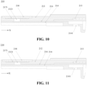
- Figs. 10 and 11 are sectional views of the exhaust channel 216b in Figs. 8 and 9 perpendicular to the Y direction respectively.
- the exhaust channel 216b is configured to communicate the ventilating film 217 with the first through hole 2141.
- the air inside the battery cell 20 can reach the exhaust channel 216b through the first through hole 2141, and pass through the exhaust channel 216b to be discharged from the ventilating film 217 so as to ensure the ventilation of the battery cell 20.
- the air inside the battery cell 20 can be discharged through the first through hole 2131 and directly reach the pressure relief component 213, so that the pressure inside the battery cell 20 is relieved through the pressure relief component 213 to ensure the safety of the battery cell 20.
- the path of the exhaust channel 216 shown in Figs. 4 to 11 is only an example.
- the exhaust channel 216 on the end cover 212 or the insulating component 214 may also have other paths, which is not limited by the present application, as long as it is able to communicate the exhaust mechanism 215 with the interior of the battery cell 20.
- the groove 216 may be provided only on the insulating component 214; or the groove 216 may be provided only on the end cover 212; or the groove 216 may be provided on both the insulating component 214 and the end cover 212. In this case, the paths of the groove on the insulating component 214 and the groove on the end cover 212 may overlap or may be different.
- a step 1212 is provided on the surface of the end cover 212, a support sheet 218 is accommodated in the step 2122, and at least one through hole 2181 is provided in the support sheet 218.
- the ventilating film 217 is located between the support sheet 218 and the end cover 212 and covers the at least one through hole 2181.
- the exhaust channel 216 is configured to communicate the at least one through hole 2181 with the interior of the battery cell 20.
- a step 2122 is provided on the surface of the end cover 212 close to the interior of the battery cell 20, a support sheet 218 is accommodated in the step 2122, and at least one through hole 2181 is provided in the support sheet 218.
- the ventilating film 217 is located between the support sheet 218 and the end cover 212 and covers the least one through hole 2181, and the exhaust channel 216 is configured to communicate the at least one through hole 2181 with the interior of the battery cell 20.
- the step 2122 may also be provided on the surface of the end cover 212 away from the interior of the battery cell 20.
- the step 2122 is provided on the surface of the end cover 212 away from the interior of the battery cell 20, a support sheet 218 is accommodated in the step 2122, and at least one through hole 2181 is provided in the support sheet 218.
- the ventilating film 2171 is located between the support sheet 218 and the end cover 212 and covers the least one through hole 2181, and the exhaust channel 216 is configured to communicate the at least one through hole 2181 with the interior of the battery cell 20.
- the support sheet 218 may be, for example, a metal sheet.
- the material of the support sheet may be aluminum, stainless steel, copper, or the like, or the support sheet 218 may also be formed from other materials with certain rigidity.
- the support sheet 218 may be fixed in the step 2122 of the end cover 212 by means of laser welding or the like, and the ventilating film 2171 may be adhered to the surface of the support sheet 218.
- the ventilating film 2171 is adhered to the surface of the support sheet 218.
- a space for accommodating the ventilating film 2171 is provided between the support sheet 218 and the end cover 212.
- the ventilating film 2171 is made from, for example, PP or PE.
- the support sheet 218 By providing the support sheet 218 and accommodating it in the step on the surface of the end cover 212, a fixing and supporting effect is provided for the ventilating film 2171, and since at least one through hole 2181 is provided in the support sheet 218, the air exchange between two sides of the ventilating film 2171 will not be affected.
- the number of through holes 2181 on the support sheet 218 may be one or more.
- N through holes 2181 are provided on the support sheet 218, N being a positive integer greater than 1.
- each through hole has an area of S2
- the total area of the through holes 2181 on the support sheet 218 is N ⁇ S2.
- the cross-sectional area of the exhaust channel 216 is S1.
- S1 H ⁇ L, where L and H are the width L and depth of the exhaust channel respectively.
- the ratio K of the cross-sectional area S of the exhaust channel 216 to the total area of the at least one through hole N ⁇ S2 is greater than or equal to 0.1% and less than or equal to 40%; preferably, K is greater than or equal to 0.2% and less than or equal to 20%; further preferably, K is greater than or equal to 0.5% and less than or equal to 15%.
- the ratio K of the cross-sectional area S of the exhaust channel 216 to the total area of the at least one through hole N ⁇ S2 is within the appropriate range as mentioned above, the exhaust capability of the ventilating film 2171 can match with that of the at least one through hole 2181.
- the size of the exhaust channel 216 affects the structure of the end cover 212 or the insulating component 214. For example, as shown in Figs. 4 to 12 , when the exhaust channel 216 is the groove 216 on the end cover 212 or the insulating component 214, the wall thickness at the corresponding position of the end cover 212 and the insulating component 214 will be reduced, affecting the structural stability of the end cover assembly 210.
- the width L of the exhaust channel 216 is greater than or equal to 0.5 mm and less than or equal to 4 mm; and/or, the depth H of the exhaust channel 216 is greater than or equal to 0.1 mm and less than or equal to 0.6 mm.
- the exhaust channel 216 is enabled to obtain better exhaust capability without having a major impact on the structure of the end cover 212 and the insulating component 214, ensuring the structural stability of the end cover assembly 210.
- the cross-section of the exhaust channel 216 shown in Fig. 13 is rectangular, and the area of its cross-section is the product of the width L and the depth H.
- the cross section of the exhaust channel 216 may also be in other shapes, such as semicircle, polygon, square, or the like, which is not limited in the present application.
- Fig. 14 is a schematic structural view of the end cover assembly 210 according to an embodiment of the present application.
- Fig. 15 is an enlarged view of the area G in Fig. 14; and
- Fig. 16 is a partial sectional view of the end cover assembly 210 in Fig. 14 at the second through hole 2141.
- a second through hole 2142 is provided in the insulating component 214 at a position corresponding to the ventilating hole 2121, and the exhaust channel 216 is configured to communicate the exhaust mechanism 215 with the second through hole 2142.
- the exhaust channel 216 is located between the ventilating hole 2121 and the second through hole 2142.
- the air inside the battery cell 20 can directly circulate to the ventilating film 2171 through the second through hole 2142, improving the ventilation efficiency of the battery cell 20.
- a baffle 2191 is provided between the second through hole 2142 and a metal component (not shown) in the battery cell 20 to isolate the end cover 212 from the metal component.
- the baffle 2191 can prevent the metal wire on the end cover 212 from overlapping with the metal component in the battery cell 20 and avoid short circuits, improving the safety of the battery cell 20.
- a connecting member 2192 is provided between the baffle 2191 and the insulating component 214 to fix the baffle 2191 to the insulating component 214.
- An exhaust gap 2193 is formed between the baffle 2191 and the insulating component 214.
- the groove 216 may not be provided on the end cover 212 and the insulating component 214, but rather ventilation is enabled between the ventilating film 2171 and the second through hole 2142 directly.
- the groove 216 can be provided on the end cover 212 and/or the insulating component 214 at the same time to optimize the exhaust efficiency of the battery cell 20. That is, the end cover assembly 210 includes both the above-mentioned groove 216 and second through hole 2142.
- the present application further provides a battery cell, including: an electrode assembly 22; a case 211 for accommodating the electrode assembly 22; and the end cover assembly 210 described in any of the above implementations.
- the end cover assembly 210 is configured to close the electrode assembly 22 in the case 211.
- the present application further provides an electrical device.
- the electrical device includes a plurality of battery cells 20 configured to supply electric energy to the electrical device.
Landscapes
- Chemical & Material Sciences (AREA)
- Chemical Kinetics & Catalysis (AREA)
- Electrochemistry (AREA)
- General Chemical & Material Sciences (AREA)
- Battery Mounting, Suspending (AREA)
- Gas Exhaust Devices For Batteries (AREA)
Abstract
Description
- The present application relates to the technical field of batteries, and more particularly to an end cover assembly of a battery cell and an electrical device.
- Energy conservation and emission reduction are the key to the sustainable development of the automobile industry. In view of this, electric vehicles have become an important part of the sustainable development of the automotive industry due to their advantages of energy conservation and environmental protection. For electric vehicles, battery technology is an important factor related to their development.
- Generally, a battery is composed of a plurality of battery cells. Each battery cell includes a case, an end cover assembly, and an electrode assembly located in the case. The end cover assembly is configured to cover the electrode assembly in the case. Battery cells need to have certain exhaust performance to avoid safety issues caused by imbalance of internal and external pressures. For this reason, it is an urgent problem to be solved to improve the exhaust efficiency and reliability of battery cells.
- The present application provides an end cover assembly of a battery cell and an electrical device that can improve the exhaust efficiency and reliability of the battery cell.
- In a first aspect, an end cover assembly for a battery cell is provided. The end cover assembly includes: an end cover, an exhaust mechanism being provided on the end cover; and an insulating component provided on the side of the end cover close to the interior of the battery cell. An exhaust channel is provided between the insulating component and the end cover to communicate the exhaust mechanism with the interior of the battery cell.
- In an embodiment of the present application, the end cover assembly of the battery cell includes an end cover and an insulating component. The insulating component is provided on the side of the end cover close to the interior of the battery cell. An exhaust mechanism is provided on the end cover assembly and an exhaust channel is provided between the insulating component and the end cover to communicate the exhaust mechanism with the interior of the battery cell. By providing an exhaust channel between the insulating component and the end cover to communicate the exhaust mechanism with the interior of the battery cell, the space between the end cover and the insulating component is increased, reducing the probability of liquid sealing, which is beneficial to circulation of the air inside the battery cell to the exhaust mechanism, thereby improving the exhaust efficiency and reliability of the battery cell.
- In an implementation, the exhaust channel includes a groove provided on the surface of the insulating component facing the end cover. By providing a groove facing the end cover on the insulating component, an exhaust channel can be formed between the end cover and the insulating component to communicate the exhaust mechanism with the interior of the battery cell, eliminating the need to add additional components and reducing the structural complexity of the end cover assembly.
- In an implementation, one end of the exhaust channel is in communication with the exhaust mechanism, and the other end of the exhaust channel is in communication with an edge of the insulating component. Usually, the area of the insulating component is smaller than that of the end cover. When one end of the exhaust channel is communication with the exhaust mechanism on the end cover and the other end is in communication with the edge of the insulating component, the air inside the battery cell can reach the exhaust mechanism via the exhaust channel, ensuring the smooth opening of the exhaust mechanism and consequently ensuring the exhaust efficiency.
- In an implementation, the exhaust channel includes a groove provided on the surface of the end cover facing the interior of the battery cell. By providing a groove facing the insulating component on the end cover, an exhaust channel can be formed between the end cover and the insulating component to communicate the exhaust mechanism with the interior of the battery cell, eliminating the need to add additional components and reducing the structural complexity of the end cover assembly.
- In an implementation, one end of the exhaust channel is in communication with the exhaust mechanism, and the other end of the exhaust channel is in communication with the position on the end cover corresponding to the edge of the insulating component. Usually, the area of the insulating component is smaller than that of the end cover. When one end of the exhaust channel is in communication with the exhaust mechanism on the end cover and the other end is in communication with the position on the end cover corresponding to the edge of the insulating component, the air inside the battery cell can reach the exhaust mechanism via the exhaust channel, providing high exhaust efficiency.
- In an implementation, the exhaust mechanism includes a pressure relief component to relieve the pressure inside the battery cell when thermal runaway occurs in the battery cell. The exhaust channel is configured to communicate the pressure relief component with the interior of the battery cell.
- When thermal runaway occurs in the battery cell, the air inside the battery cell can reach the pressure relief component through the exhaust channel between the insulating component and the end cover, thereby relieving the pressure through the pressure relief component. The exhaust channel facilitates circulation of the air inside the battery cell to the pressure relief component, thereby improving the safety of the battery cell.
- In an implementation, a ventilating structure is provided on the end cover. The ventilating structure includes a ventilating hole and a ventilating film covering the ventilating hole, and the exhaust channel is configured to communicate the ventilating structure with the interior of the battery cell.
- The ventilating hole and the ventilating film on the exhaust mechanism are configured to balance the air pressure of the battery cell and the outside world. The exhaust channel between the insulating component and the end cover facilitates circulation of the air inside the battery cell to the ventilating film, improving the ventilation efficiency of the battery cell.
- In an implementation, a step is provided on the surface of the end cover close to the interior of the battery cell, a support sheet is accommodated in the step, and at least one through hole is provided in the support sheet. The ventilating film is located between the support sheet and the end cover and covers the at least one through hole, and the exhaust channel is configured to communicate the at least one through hole with the interior of the battery cell. By providing the support sheet and accommodating it in the step on the surface of the end cover, a fixing and supporting effect is provided for the ventilating film, and since at least one through hole is provided in the support sheet, the air exchange between two sides of the ventilating film will not be affected.
- In an implementation, the ratio of the cross-sectional area of the exhaust channel to the total area of the at least one through hole is greater than or equal to 0.1% and less than or equal to 40%; preferably, greater than or equal to 0.2% and less than or equal to 20%; further preferably, greater than or equal to 0.5% and less than or equal to 15%. When the ratio of the cross-sectional area of the exhaust channel to the total area of the at least one through hole is within the appropriate range as described above, the exhaust capability of the ventilating film can match with that of the at least one through hole. It is avoided that the total area of at least one through hole is so small that the air passing through the ventilating film cannot be discharged from the at least one through hole in time, and it is also avoided that the total area of the at least one through hole is so large that the reliability of fixing and supporting of the ventilating film by the support sheet is compromised.
- In an implementation, the exhaust mechanism further includes a pressure relief component, a first through hole is provided in the insulating component at a position corresponding to the pressure relief component, and the exhaust channel is configured to communicate the ventilating structure with the first through hole. By providing a first through hole on the insulating component at a position corresponding to the pressure relief component, the exhaust channel can be formed between the first through hole and the exhaust mechanism, and the air inside the battery cell can reach the ventilating structure along the first through hole through the exhaust channel, further improving the ventilation efficiency of the battery cell.
- In an implementation, a second through hole is provided in the insulating component at a position corresponding to the ventilating structure, and the exhaust channel is configured to communicate the ventilating structure with the second through hole. By providing a second through hole on the insulating component at a position corresponding to the ventilating film, the air inside the battery cell can directly circulate to the ventilating structure through the second through hole, further improving the ventilation efficiency of the battery cell.
- In an implementation, a baffle is provided between the second through hole and the metal component in the battery cell to isolate the end cover from the metal component. The baffle can prevent the metal wire on the end cover from overlapping with the metal component in the battery cell and avoid short circuits, improving the safety of the battery cell.
- In an implementation, a connecting member is provided between the baffle and the insulating component to fix the baffle to the insulating component. An exhaust gap is formed between the baffle and the insulating component.
- In an implementation, the width of the exhaust channel is greater than or equal to 0.5 mm and less than or equal to 4 mm; and/or the depth of the exhaust channel is greater than or equal to 0.1 mm and less than or equal to 0.6 mm. When the size of the exhaust channel is within the appropriate range as mentioned above, the exhaust channel can obtain better exhaust capability without having a major impact on the structure of the end cover and the insulating component, ensuring the structural stability of the end cover assembly.
- In a second aspect, a battery cell is provided, including: an electrode assembly; a case to accommodate the electrode assembly; and an end cover assembly described in the first aspect or any implementation of the first aspect, the end cover assembly being configured to close the electrode assembly within the case.
- In a third aspect, an electrical device is provided, including a plurality of battery cells described in the first aspect, the battery cells being configured to supply electric energy to the electrical device.
- In order to illustrate the technical solutions of the embodiments of the present application more clearly, the drawings required in the embodiments of the present application will be briefly introduced below. Obviously, the drawings described below represent only some embodiments of the present application. For those of ordinary skill in the art, other drawings can also be obtained according to the drawings without any creative effort.
-
Fig. 1 is a schematic structural view of a vehicle according to an embodiment of the present application; -
Fig. 2 is a schematic structural view of a battery according to an embodiment of the present application; -
Fig. 3 is a schematic structural view of a battery cell according to an embodiment of the present application; -
Fig. 4 is an exploded view of an end cover assembly according to an embodiment of the present application; -
Fig. 5 is a partial sectional view of an exhaust channel of the end cover assembly shown inFig. 4 ; -
Fig. 6 is an exploded view of an end cover assembly according to another embodiment of the present application; -
Fig. 7 is a partial sectional view of an exhaust channel of the end cover assembly shown inFig. 6 ; -
Fig. 8 is an exploded view of an end cover assembly according to yet another embodiment of the present application; -
Fig. 9 is an exploded view of an end cover assembly according to still another embodiment of the present application; -
Fig. 10 is a schematic partial view of an exhaust channel of the end cover assembly shown inFig. 8 ; -
Fig. 11 is a schematic partial view of an exhaust channel of the end cover assembly shown inFig. 9 ; -
Fig. 12 is a schematic view of a support sheet on an end cover assembly according to an embodiment of the present application; -
Fig. 13 is a schematic view showing the dimensions of an exhaust channel according to an embodiment of the present application; -
Fig. 14 is an exploded view of an end cover assembly according to yet another embodiment of the present application; -
Fig. 15 is an enlarged view of the area G in the end cover assembly shown inFig. 14 ; and -
Fig. 16 is a partial sectional view of a second through hole in the end cover assembly shown inFig. 14 . - In the drawings, the figures are not drawn to actual scale.
- Implementations of the present application will be described in further detail hereinafter in conjunction with the drawings and embodiments. The following detailed description of the embodiments and the drawings are used to illustrate the principles of the present application by way of example, but should not be used to limit the scope of the present application, that is, the present application is not limited to the described embodiments.
- Implementations of the present application will be described in further detail hereinafter in conjunction with the drawings and embodiments. The following detailed description of the embodiments and the drawings are used to illustrate the principles of the present application by way of example, but should not be used to limit the scope of the present application, that is, the present application is not limited to the described embodiments.
- In the description of the present application, it should be noted that, unless otherwise stated, "plurality of" means two or more; the orientation or positional relationships indicated by the terms "upper", "lower", "left", "right", "inner" and "outer" are only for facilitating the description of the present application and simplifying the description, rather than indicating or implying that the apparatus or element referred to must have a particular orientation or be constructed and operated in a particular orientation, and therefore will not be interpreted as limiting the present application. In addition, the terms "first", "second" and "third" are only used for descriptive purposes, and cannot be construed as indicating or implying relative importance. "Vertical" does not mean being vertical in the strict sense, but within the permissible range of error. "Parallel" does not mean being parallel in the strict sense, but within the permissible range of error.
- Orientation words appearing in the following description are all directions shown in the drawings, and do not limit the specific structure of the present application. In the description of the present application, it should also be noted that, unless otherwise expressly specified and defined, the terms "install", "connected" and "connect" should be understood in a broad sense, for example, they may be fixedly connected, detachably connected or integrally connected; and they may be directly connected or indirectly connected through an intermediate medium. For those of ordinary skill in the art, the specific meanings of the above terms in the present application may be understood according to specific circumstances.
- In the embodiments of the present application, the same reference numerals indicate the same parts and, for the sake of brevity, the detailed description of the same parts is omitted in the different embodiments. It should be understood that the dimensions such as the thickness, length, and width of various components in the embodiments of the present application shown in the drawings, as well as the dimensions such as the overall thickness, length, and width of the integrated device are illustrative only and shall not constitute any limitation on the present application.
- In the present application, the battery cell may include a lithium-ion battery, a lithium-sulfur battery, a sodium-lithium-ion battery, a sodium-ion battery, a magnesium-ion battery, or the like, which is not limited in embodiments of the present application. The battery cell may be cylindrical, flat, cuboid, or in other shapes, which is also not limited in embodiments of the present application. The battery cells are generally divided into three types according to packaging manners: cylindrical battery cells, prismatic battery cells, and pouch cells, which is also not limited in embodiments of the present application.
- The battery mentioned in the embodiments of the present application refers to a single physical module including one or more battery cells to provide a higher voltage and capacity. For example, the battery mentioned in the present application may include a battery module, a battery pack, or the like. The battery generally includes a box for encapsulating one or more battery cells. The box can prevent liquids or other foreign matters from affecting the charging or discharging of the battery cells.
- Usually, a battery cell relies on the gap between its end cover and the insulating component located on the side of the end cover close to the interior of the battery cell for air exchange. When there is liquid in the gap, liquid sealing will occur, affecting the discharge performance of the battery cell, which may easily cause safety problems due to imbalance of internal and external pressures of the battery cell.
- In view of this, embodiments of the present application provide an end cover assembly including an end cover and an insulating component. An exhaust channel is provided between the insulating component and the end cover to communicate the exhaust mechanism with the interior of the battery cell. Therefore, the space between the end cover and the insulating component is increased, and the probability of liquid sealing is reduced, which is beneficial to circulation of the air inside the battery cell to the exhaust mechanism, thereby improving the exhaust efficiency and reliability of the battery cell.
- The technical solutions described in embodiments of the present application are all applicable to a variety of electrical devices using batteries.
- The electrical devices may be, but not limited to, a vehicle, a mobile phone, a portable device, a laptop computer, a ship, a spacecraft, an electric toy, an electric tool, and the like. The vehicle may be a fuel vehicle, an air vehicle or a new energy vehicle. The new energy vehicle may be an all-electric vehicle, a hybrid electric vehicle, an extended-range electric vehicle, or the like. The spacecraft includes airplanes, rockets, space shuttles, spaceships, and the like. The electric toy includes fixed or mobile electric toys, such as game consoles, electric car toys, electric ship toys and electric aircraft toys. The electric tool includes metal cutting electric tools, grinding electric tools, assembly electric tools and railway electric tools, such as electric drills, electric grinders, electric wrenches, electric screwdrivers, electric hammers, impact drills, concrete vibrators and electric planers. Embodiments of the present application do not impose special limitations on the above electrical device.
- For the convenience of illustration, the following embodiments are illustrated with the electrical device being a vehicle as an example.
- As an example, as shown in
Fig.1 , a schematic structural diagram of avehicle 1 according to an embodiment of the present application is shown. Thevehicle 1 may be a fuel vehicle, a gas vehicle, or a new energy vehicle, and the new energy vehicle may be an all-electric vehicle, a hybrid vehicle, an extended range electric vehicle, or the like. The interior of thevehicle 1 can be provided with amotor 40, acontroller 30, and abattery 10, and thecontroller 30 is used for controlling thebattery 10 to power themotor 40. As an example, thebattery 10 may be arranged at the bottom or the head or the tail of thevehicle 1. Thebattery 10 may be configured to supply power to thevehicle 1. As an example, thebattery 10 may be used as an operating power source of thevehicle 1, which is used for a circuit system of thevehicle 1, for example, for operation power requirements of thevehicle 1 during starting, navigation and running. In another embodiment of the present application, thebattery 10 can serve not only as an operating power supply for thevehicle 1, but also as a driving power source for thevehicle 1, so as to replace or partially replace fuel or natural air to provide driving power for thevehicle 1. Thebattery 10 may also be called a battery pack. - For example,
Fig. 2 shows a schematic structural view of abattery 10 according to an embodiment of the present application. Thebattery 10 may include a plurality ofbattery cells 20. Thebattery 10 may further include abox 11, thebox 11 is of a hollow structure inside, and the plurality ofbattery cells 20 are accommodated in thebox 11.Fig. 2 shows a possible implementation of thebox 11 according to an embodiment of the present application. As shown inFig. 2 , thebox 11 may include two parts, which are referred to here as afirst box portion 111 and asecond box portion 112 respectively, and thefirst box portion 111 and thesecond box portion 112 are snap-fitted together. The shapes of thefirst box portion 111 and thesecond box portion 112 may be determined according to the combined shape of the plurality ofbattery cells 20, and at least one of thefirst box portion 111 and thesecond box portion 112 has an opening. For example, as shown inFig. 2 , both thefirst box portion 111 and thesecond box portion 112 may be hollow cuboids and each has only one surface being an opening surface, the opening of thefirst box portion 111 and the opening of thesecond box portion 112 are disposed opposite to each other, and thefirst box portion 111 and thesecond box portion 112 are snap-fitted together to form thebox 11 having an enclosed cavity. - As another example, in contrast to what is shown in
Fig. 2 , only one of thefirst box portion 111 and thesecond box portion 112 may be a hollow cuboid with an opening, and the other one may be of a plate shape to cover the opening. For example, here thesecond box portion 112 is a hollow cuboid and has only one surface being an opening surface, and thefirst box portion 111 is of a plate shape. Then the opening of thesecond box portion 112 is covered by thefirst box portion 111 to form thebox 11 having an enclosed cavity for accommodating the plurality ofbattery cells 20. The plurality ofbattery cells 20 are combined in parallel, in series or in a hybrid pattern, and then placed in thebox 11 formed by snap-fitting thefirst box portion 111 to thesecond box portion 112. - In some embodiments, the
battery 10 may also include other structures, which will not be described here. For example, thebattery 10 may further include a busbar component configured to realize electrical connection between the plurality ofbattery cells 20, such as parallel connection, series connection or hybrid connection. Specifically, the busbar component may realize electrical connection between thebattery cells 20 by connecting electrode terminals of thebattery cells 20. In some embodiments, the busbar component may be fixed to the electrode terminals of thebattery cells 20 by welding. Electric energy from the plurality ofbattery cells 20 may be further led out via an electrically conductive mechanism through thebox 11. - Depending on different power demands, the number of
battery cells 20 in thebattery 10 may be set to any value. The plurality ofbattery cells 20 may be connected in series, parallel or hybrid pattern to achieve larger capacity or power, where the term hybrid pattern means mixture of series and parallel connections. Since eachbattery 10 may include a large number ofbattery cells 20, in order to facilitate installation, thebattery cells 20 may be arranged in groups, and each group ofbattery cells 20 forms a battery module 200. The number ofbattery cells 20 included in the battery module 200 is not limited and may be set according to the demand. That is, the plurality ofbattery cells 20 may directly form abattery 10, or may form battery modules first, and then the battery modules form abattery 10. - As an example, as shown in
Fig. 3 , a possible schematic structural view of abattery cell 20 is shown. Thebattery cell 20 includes one ormore electrode assemblies 22, acase 211 and anend cover 212. Thecase 211 and theend cover 212 form a housing orbattery case 21. The wall of thecase 211 and theend cover 212 are both called the wall of thebattery cell 20. For a cuboid-shapedbattery cell 20, the wall of thecase 211 includes a bottom wall and four side walls. The shape of thecase 211 is determined according to the combined shape of one ormore electrode assemblies 22. For example, thecase 211 may be a hollow cuboid, cube, or cylinder, and one of the surfaces of thecase 211 has an opening to facilitate placing the one ormore electrode assemblies 22 in thecase 211. For example, when thecase 211 is a hollow cuboid or cube, one of the planes of thecase 211 is an opening surface, that is, this plane has no walls so that the inside and outside of thecase 211 are in communication with each other. When thecase 211 is a hollow cylinder, the end surface of thecase 211 is an opening surface, that is, this end surface does not have a wall so that the inside and outside of thecase 211 are in communication with each other. Theend cover 212 covers the opening and is connected with thecase 211 to form an enclosed cavity in which theelectrode assemblies 22 are placed. Thecase 211 is filled with electrolyte, such as electrolyte solution. - As shown in
Fig. 3 , an insulatingcomponent 214 is further provided on the side of theend cover 212 facing theelectrode assembly 22. The insulatingcomponent 214 may also be called lower plastic. - The
battery cell 20 may further include twoelectrode terminals 214, which may be provided on theend cover 212. Theend cover 212 is generally in the shape of a flat plate, and the twoelectrode terminals 214 are fixed to the flat plate surface of theend cover 212. The twoelectrode terminals 214 are apositive electrode terminal 214a and anegative electrode terminal 214b respectively. Each of theelectrode terminals 214 is provided with a corresponding connectingmember 23, which may alternatively be referred to as a current collectingmember 23, located between theend cover 212 and theelectrode assembly 22 for electrically connecting theelectrode assembly 22 and theelectrode terminal 214. - As shown in
Fig. 3 , eachelectrode assembly 22 has afirst tab 221a and asecond tab 222a. Thefirst tab 221a and thesecond tab 222a have opposite polarities. For example, when thefirst tab 221a is a positive electrode tab, thesecond tab 222a is a negative electrode tab. Thefirst tab 221a of one ormore electrode assemblies 22 is connected to one electrode terminal via one connectingmember 23, and thesecond tab 222a of the one ormore electrode assemblies 22 is connected to the other electrode terminal via the other connectingmember 23. For example, thepositive electrode terminal 214a is connected to the positive electrode tab via one connectingmember 23, and thenegative electrode terminal 214b is connected to the negative electrode tab via the other connectingmember 23. - In the
battery cell 20, asingle electrode assembly 22 or a plurality ofelectrode assemblies 22 may be provided according to actual usage requirements. As shown inFig. 3 , fourindependent electrode assemblies 22 are provided in thebattery cell 20. - It should be understood that the plurality of
battery cells 20 included in thebattery 10 in the embodiments of the present application may be arranged and placed in any orientation in thebox 11. For example, taking the cuboid shapedbattery cell 20 as shown inFig. 3 as an example, as shown inFig. 2 , a plurality ofbattery cells 20 may be installed in thebox 11 in the vertical direction as shown inFig. 3 in such a manner that, after installation, the end covers 212 of the plurality ofbattery cells 20 face theupper box 111, and the bottom walls of thecases 211 of thebattery cells 20 face thelower box 112. As another example, unlikeFig. 2 , a plurality ofbattery cells 20 as shown inFig. 3 may also be arranged horizontally in thebox 11. - In the end cover assembly shown in
Fig. 3 , when no channel for exhausting thebattery cell 20 is provided between the insulatingcomponent 214 and theend cover 212, the air inside thebattery cell 20 can only go through air exchange via the gap between theend cover 212 and thelower plastic 214. When liquid is present in the gap, liquid sealing will occur, which makes it impossible for thebattery cell 20 to be effectively ventilated. - To this end, the present application provides an
end cover assembly 210 that can effectively improve the exhaust efficiency of thebattery cell 20. Theend cover assembly 210 of embodiments of the present application will be described in detail below in conjunction withFigs. 4 to 28 . It should be understood that the end cover assembly shown inFig. 3 may be replaced by theend cover assembly 210 in the embodiment of the present application as described below. -
Figs. 4 to 28 illustrate theend cover assembly 210 according to embodiments of the present application. Theend cover assembly 210 in the embodiments of the present application is used for thebattery cell 20. The end cover assembly210includes anend cover 212 and an insulatingcomponent 214. Anexhaust mechanism 215 is provided on theend cover 212. The insulatingcomponent 214 is arranged on the side of theend cover 212 close to the interior of thebattery cell 20. Anexhaust channel 216 is provided between the insulatingcomponent 214 and theend cover 212. Theexhaust channel 216 is configured to communicate theexhaust mechanism 215 with the interior of thebattery cell 20. - It should be understood that the interior of the
battery cell 20 here refers to the part of thebattery cell 20 located below the insulatingcomponent 214, that is, the space enclosed by the insulatingcomponent 214 and thecase 211 in thebattery cell 20. Specifically, it includes the space formed between the surface of the insulatingcomponent 214 facing theelectrode assembly 22 and the bottom wall of thecase 211, and the space formed between the plane where the side surface of the insulatingcomponent 214 is located and the side wall of thecase 211. - The
exhaust mechanism 215 may include, for example, apressure relief component 213 provided on theend cover 212, a ventilatingstructure 217, or other structures for air exchange between thebattery cell 20 and the outside world. The ventilatingstructure 217 is also called a ventilating valve, and may include aventilating hole 2121 and aventilating film 2171 covering theventilating hole 2121. Theexhaust channel 216 is located between theend cover 212 and the insulatingcomponent 213 to communicate theexhaust mechanism 215 with the interior of thebattery cell 20 so as to form a path for air circulation between the interior of thebattery cell 20 and theexhaust mechanism 215. - The insulating
component 215 is configured to isolate theend cover 212 from the interior of thebattery cell 20 and may be made of plastic. - By providing an
exhaust channel 216 between the insulatingcomponent 214 and theend cover 212 to communicate theexhaust mechanism 215 with the interior of thebattery cell 20, the space between theend cover 212 and the insulatingcomponent 214 is increased, reducing the probability of liquid sealing, which is beneficial to circulation of the air inside thebattery cell 20 to theexhaust mechanism 215, thereby improving the exhaust efficiency and reliability of thebattery cell 20. -
Figs. 4 and 5 show a possible implementation of theend cover assembly 210, whereFig. 4 is an exploded view of theend cover assembly 210, andFig. 5 is a partial sectional view of theend cover assembly 210 shown inFig. 4 at theexhaust channel 216. - In an implementation, as shown in
Figs. 4 and 5 , theexhaust channel 216 includes agroove 216 provided on the surface of the insulatingcomponent 214 facing theend cover 212. By providing thegroove 216 facing theend cover 212 on the insulatingcomponent 214, anexhaust channel 216 can be formed between theend cover 212 and the insulatingcomponent 214 to communicate theexhaust mechanism 215 with the interior of thebattery cell 20, eliminating the need to add additional components and reducing the structural complexity of theend cover assembly 210. - In an implementation, one end of the
exhaust channel 216 is in communication with theexhaust mechanism 215, and the other end of theexhaust channel 216 is in communication with an edge of the insulatingcomponent 214. Generally, the area of the insulatingcomponent 214 is smaller than that of theend cover 212. When one end of theexhaust channel 216 is in communication with theexhaust mechanism 215 on theend cover 212 and the other end is in communication with the edge of the insulatingcomponent 214, the air inside thebattery cell 20 can reach theexhaust mechanism 215 through theexhaust channel 216 along the inner wall of thecase 211 of thebattery cell 20, thereby providing high exhaust efficiency. For example, as shown inFigs. 4 and 5 , one end of theexhaust channel 216 is in communication with theexhaust mechanism 215, and the other end is in communication with the edge of the insulatingcomponent 214. -
Figs. 6 and 7 show another possible implementation of theend cover assembly 210, whereFig. 6 is an exploded view of theend cover assembly 210, andFig. 7 is a partial sectional view of theend cover assembly 210 shown inFig. 6 at theexhaust channel 216. - In an implementation, as shown in
Figs.6 and 7 , theexhaust channel 216 includes agroove 216 provided on the surface of theend cover 212 facing the interior of thebattery cell 20. By providing thegroove 216 facing the insulatingcomponent 214 on theend cover 212, anexhaust channel 216 can be formed between theend cover 212 and the insulatingcomponent 214 to communicate theexhaust mechanism 215 with the interior of thebattery cell 20, eliminating the need to add additional components and reducing the structural complexity of theend cover assembly 210. - In an implementation, one end of the
exhaust channel 216 is in communication with theexhaust mechanism 215, and the other end of theexhaust channel 216 is in communication with the position on theend cover 212 corresponding to the edge of the insulatingcomponent 214. Generally, the area of the insulatingcomponent 214 is smaller than that of theend cover 212. When one end of theexhaust channel 216 is in communication with theexhaust mechanism 215 on theend cover 212 and the other end is in communication with the position on theend cover 212 corresponding to the edge of the insulatingcomponent 214, the air inside thebattery cell 20 can reach theexhaust mechanism 215 through theexhaust channel 216 along the inner wall of thecase 211 of thebattery cell 20, thereby providing high exhaust efficiency. For example, as shown inFigs. 6 and 7 , one end of theexhaust channel 216 is in communication with theexhaust mechanism 215, and the other end is in communication with the position on theend cover 212 corresponding to the edge of the insulatingcomponent 214. - In an implementation, as shown in
Figs. 4 to 7 , a ventilatingstructure 217 is provided on theend cover 212. The ventilating structure includes aventilating hole 2121 and aventilating film 2171 covering theventilating hole 2121. Theexhaust channel 216 is configured to communicate theventilating structure 217 with the interior of thebattery cell 20. Theventilating hole 2121 and theventilating film 2171 on theexhaust mechanism 215 are configured to balance the air pressure of thebattery cell 20 and the outside world. Theexhaust channel 216 between the insulatingcomponent 214 and theend cover 212 facilitates circulation of the air inside thebattery cell 20 to theventilating film 2171, improving the ventilation efficiency of thebattery cell 20. The shape of theventilating hole 2121 may be, for example, circular, square, or the like, which is not limited in the present application. - The
ventilating film 2171 has a ventilating function, and may be made of PP (polypropylene), PE (polyethylene), PU (polyurethane) or the like. The air inside thebattery cell 20 needs to pass through theventilating film 2171 when it is discharged. Theventilating film 2171 can allow the air inside thebattery cell 20 to circulate to the outside, and can block water vapor and the like from outside thebattery cell 20 from entering the inside of thebattery cell 20. - For example, as shown in
Figs. 4 and 5 , theexhaust channel 216 is agroove 216 on the insulatingcomponent 214, one end of which is in communication with the edge of the insulatingcomponent 214, and the other end is in communication with theventilating film 2171. As another example, as shown inFigs. 6 and 7 , theexhaust channel 216 is agroove 216 on theend cover 212, one end of which is in communication with the position on theend cover 212 corresponding to the edge of the insulatingcomponent 214, and the other end is in communication with theventilating film 2171. - In another implementation, the
exhaust mechanism 215 includes apressure relief component 213 to relieve the pressure when thermal runaway occurs in thebattery cell 20, and theexhaust channel 216 is configured to communicate thepressure relief component 213 with the interior of thebattery cell 20. - Specifically, the
pressure relief mechanism 213 is configured to be actuated to relieve the internal pressure or temperature of abattery cell 20 when the internal pressure or temperature reaches a threshold. Thepressure relief component 213 may have various possible pressure relief structures, which is not limited in the embodiments of the present application. For example, thepressure relief component 213 may be a temperature-sensitive pressure relief component configured to melt when the internal temperature of thebattery cell 20 provided with thepressure relief component 213 reaches a threshold; and/or thepressure relief component 213 may be a pressure-sensitive pressure relief component configured to rupture when the internal air pressure of thebattery cell 20 provided with thepressure relief component 213 reaches a threshold. - As such, when thermal runaway occurs in the
battery cell 20, the air inside thebattery cell 20 can reach thepressure relief component 213 through theexhaust channel 216 between the insulatingcomponent 214 and theend cover 212 and the pressure inside thebattery cell 20 is relieved through thepressure relief component 213. Theexhaust channel 216 facilitates circulation of the air inside thebattery cell 20 to thepressure relief component 213, thereby improving the safety of thebattery cell 20. - For example, as shown in
Fig. 8 or 9 , where inFig. 8 , theexhaust channel 216 is a groove on the insulatingcomponent 214 as an example, and inFig. 9 , theexhaust channel 216 is a groove on theend cover 214 as an example, theexhaust channel 216 communicates both thepressure relief component 213 and theventilating film 2171 with the interior of thebattery cell 20. For example, as shown inFig. 8 , theexhaust channel 216 is agroove 216 on the insulatingcomponent 214. Thegroove 216 includes asection 216a parallel to the Y direction and asection 216b parallel to the X direction, where the X direction is the long side direction of theend cover assembly 210, and the Y direction is the short side direction of theend cover assembly 210. It can be seen that one end of theexhaust channel 216 is in communication with the edge of the insulatingcomponent 214, and the other end is in communication with the ventilating structure 271, and is also in communication with thepressure relief component 213 via the ventilating structure 271. As another example, as shown inFig. 9 , theexhaust channel 216 is agroove 216 on theend cover 212. Thegroove 216 includes asection 216a parallel to the Y direction and asection 216b parallel to the X direction. It can be seen that one end of theexhaust channel 216 is in communication with the position on theend cover 212 corresponding to the edge of the insulatingcomponent 214, and the other end is in communication with the ventilating structure 271, and is also in communication with thepressure relief component 213 via the ventilating structure 271. - In practical applications, the
exhaust channel 216 may only be configured to communicate theventilating structure 217 with the interior of thebattery cell 20. For example, theexhaust channel 216 may only include thesection 216a of theexhaust channel 216 inFigs. 4 to 7 and not theother section 216b; or, theexhaust channel 216 is configured to communicate both thepressure relief component 213 with the interior of thebattery cell 20 and theventilating film 2171 with the interior of thebattery cell 20, for example, as shown inFigs. 8 and 9 ; or, theexhaust channel 216 may also only be configured to communicate thepressure relief component 213 with the interior of the battery cell 20 (not shown). - In an implementation, the
exhaust mechanism 215 includes aventilating structure 217 and apressure relief component 213. A first throughhole 2141 is provided in the insulatingcomponent 214 at a position corresponding to thepressure relief component 213. Theexhaust channel 216 is configured to communicate theventilating structure 217 with the first throughhole 2141. By providing the first throughhole 2141 on the insulatingcomponent 214 at a position corresponding to thepressure relief component 213, theexhaust channel 216 can be formed between the first throughhole 2141 and theexhaust mechanism 215, and the air inside thebattery cell 20 can reach theventilating film 2171 through theexhaust channel 216 along the first throughhole 2141, further improving the ventilation efficiency. - For example, the
exhaust channel 216 may include only thesection 216b of theexhaust channel 210 shown inFigs. 8 to 9 and not theother section 216a.Figs. 10 and 11 are sectional views of theexhaust channel 216b inFigs. 8 and 9 perpendicular to the Y direction respectively. As shown inFigs. 10 and 11 , theexhaust channel 216b is configured to communicate theventilating film 217 with the first throughhole 2141. The air inside thebattery cell 20 can reach theexhaust channel 216b through the first throughhole 2141, and pass through theexhaust channel 216b to be discharged from the ventilatingfilm 217 so as to ensure the ventilation of thebattery cell 20. - Meanwhile, since the first through
hole 2141 is arranged opposite to thepressure relief component 213, when thermal runaway occurs in thebattery cell 20, the air inside thebattery cell 20 can be discharged through the first through hole 2131 and directly reach thepressure relief component 213, so that the pressure inside thebattery cell 20 is relieved through thepressure relief component 213 to ensure the safety of thebattery cell 20. - It should be understood that the path of the
exhaust channel 216 shown inFigs. 4 to 11 is only an example. Theexhaust channel 216 on theend cover 212 or the insulatingcomponent 214 may also have other paths, which is not limited by the present application, as long as it is able to communicate theexhaust mechanism 215 with the interior of thebattery cell 20. - In the embodiment of the present application, the
groove 216 may be provided only on the insulatingcomponent 214; or thegroove 216 may be provided only on theend cover 212; or thegroove 216 may be provided on both the insulatingcomponent 214 and theend cover 212. In this case, the paths of the groove on the insulatingcomponent 214 and the groove on theend cover 212 may overlap or may be different. - In an implementation, as shown in
Figs. 4 to 11 , a step 1212 is provided on the surface of theend cover 212, asupport sheet 218 is accommodated in thestep 2122, and at least one throughhole 2181 is provided in thesupport sheet 218. Theventilating film 217 is located between thesupport sheet 218 and theend cover 212 and covers the at least one throughhole 2181. Theexhaust channel 216 is configured to communicate the at least one throughhole 2181 with the interior of thebattery cell 20. - For example, as shown in
Figs. 4 and 5 , astep 2122 is provided on the surface of theend cover 212 close to the interior of thebattery cell 20, asupport sheet 218 is accommodated in thestep 2122, and at least one throughhole 2181 is provided in thesupport sheet 218. Theventilating film 217 is located between thesupport sheet 218 and theend cover 212 and covers the least one throughhole 2181, and theexhaust channel 216 is configured to communicate the at least one throughhole 2181 with the interior of thebattery cell 20. - As another example, as shown in
Figs. 6 and 7 , thestep 2122 may also be provided on the surface of theend cover 212 away from the interior of thebattery cell 20. Thestep 2122 is provided on the surface of theend cover 212 away from the interior of thebattery cell 20, asupport sheet 218 is accommodated in thestep 2122, and at least one throughhole 2181 is provided in thesupport sheet 218. Theventilating film 2171 is located between thesupport sheet 218 and theend cover 212 and covers the least one throughhole 2181, and theexhaust channel 216 is configured to communicate the at least one throughhole 2181 with the interior of thebattery cell 20. - The
support sheet 218 may be, for example, a metal sheet. For example, the material of the support sheet may be aluminum, stainless steel, copper, or the like, or thesupport sheet 218 may also be formed from other materials with certain rigidity. Thesupport sheet 218 may be fixed in thestep 2122 of theend cover 212 by means of laser welding or the like, and theventilating film 2171 may be adhered to the surface of thesupport sheet 218. For example, as shown inFigs. 4 to 11 , theventilating film 2171 is adhered to the surface of thesupport sheet 218. A space for accommodating theventilating film 2171 is provided between thesupport sheet 218 and theend cover 212. Theventilating film 2171 is made from, for example, PP or PE. - By providing the
support sheet 218 and accommodating it in the step on the surface of theend cover 212, a fixing and supporting effect is provided for theventilating film 2171, and since at least one throughhole 2181 is provided in thesupport sheet 218, the air exchange between two sides of theventilating film 2171 will not be affected. - The number of through
holes 2181 on thesupport sheet 218 may be one or more. For example, as shown inFig. 12 , N throughholes 2181 are provided on thesupport sheet 218, N being a positive integer greater than 1. Assume that each through hole has an area of S2, then the total area of the throughholes 2181 on thesupport sheet 218 is N×S2. The cross-sectional area of theexhaust channel 216 is S1. When the cross-section of theexhaust channel 216 is rectangular, S1=H×L, where L and H are the width L and depth of the exhaust channel respectively. - The ratio of the cross-sectional area S1 of the
exhaust channel 216 to the total area of at least one through hole N×S2 is K=S1/(N×S2), where K should be within an appropriate range. If the total area of the at least one throughhole 2181 is too small, the air passing through theventilating film 2171 cannot be discharged from the at least one throughhole 2181 in time; and if the total area of the at least one throughhole 2181 is too large, the reliability of fixing and supporting of theventilating film 2171 by the support sheet will be compromised. - In an implementation, the ratio K of the cross-sectional area S of the
exhaust channel 216 to the total area of the at least one through hole N×S2 is greater than or equal to 0.1% and less than or equal to 40%; preferably, K is greater than or equal to 0.2% and less than or equal to 20%; further preferably, K is greater than or equal to 0.5% and less than or equal to 15%. When the ratio K of the cross-sectional area S of theexhaust channel 216 to the total area of the at least one through hole N×S2 is within the appropriate range as mentioned above, the exhaust capability of theventilating film 2171 can match with that of the at least one throughhole 2181. - Since the
exhaust channel 216 is located between theend cover 212 and the insulatingcomponent 214, the size of theexhaust channel 216 affects the structure of theend cover 212 or the insulatingcomponent 214. For example, as shown inFigs. 4 to 12 , when theexhaust channel 216 is thegroove 216 on theend cover 212 or the insulatingcomponent 214, the wall thickness at the corresponding position of theend cover 212 and the insulatingcomponent 214 will be reduced, affecting the structural stability of theend cover assembly 210. - In an implementation, as shown in
Fig. 13 , which is a side view ofFig. 6 , taking the exhaust channel being a groove on theend cover 212 as an example, the width L of theexhaust channel 216 is greater than or equal to 0.5 mm and less than or equal to 4 mm; and/or, the depth H of theexhaust channel 216 is greater than or equal to 0.1 mm and less than or equal to 0.6 mm. When the width L and/or depth H of theexhaust channel 216 is within the appropriate range as mentioned above, theexhaust channel 216 is enabled to obtain better exhaust capability without having a major impact on the structure of theend cover 212 and the insulatingcomponent 214, ensuring the structural stability of theend cover assembly 210. - The cross-section of the
exhaust channel 216 shown inFig. 13 is rectangular, and the area of its cross-section is the product of the width L and the depth H. The cross section of theexhaust channel 216 may also be in other shapes, such as semicircle, polygon, square, or the like, which is not limited in the present application. -
Fig. 14 is a schematic structural view of theend cover assembly 210 according to an embodiment of the present application.Fig. 15 is an enlarged view of the area G inFig. 14; and Fig. 16 is a partial sectional view of theend cover assembly 210 inFig. 14 at the second throughhole 2141. In an implementation, a second throughhole 2142 is provided in the insulatingcomponent 214 at a position corresponding to theventilating hole 2121, and theexhaust channel 216 is configured to communicate theexhaust mechanism 215 with the second throughhole 2142. For example, as shown in Figs. 25 to 28, theexhaust channel 216 is located between theventilating hole 2121 and the second throughhole 2142. By providing a second throughhole 2142 on the insulatingcomponent 214 at a position corresponding to theventilating film 2171, the air inside thebattery cell 20 can directly circulate to theventilating film 2171 through the second throughhole 2142, improving the ventilation efficiency of thebattery cell 20. - In an implementation, as shown in
Figs. 14 to 16 , abaffle 2191 is provided between the second throughhole 2142 and a metal component (not shown) in thebattery cell 20 to isolate theend cover 212 from the metal component. Thebaffle 2191 can prevent the metal wire on theend cover 212 from overlapping with the metal component in thebattery cell 20 and avoid short circuits, improving the safety of thebattery cell 20. - In an implementation, as shown in
Figs. 14 to 16 , a connectingmember 2192 is provided between thebaffle 2191 and the insulatingcomponent 214 to fix thebaffle 2191 to the insulatingcomponent 214. Anexhaust gap 2193 is formed between thebaffle 2191 and the insulatingcomponent 214. - It can be understood that when the second through
hole 2142 is provided in the insulatingcomponent 214, for example, as shown inFigs. 14 to 16 , thegroove 216 may not be provided on theend cover 212 and the insulatingcomponent 214, but rather ventilation is enabled between theventilating film 2171 and the second throughhole 2142 directly. Alternatively, when the second throughhole 2142 is provided in the insulatingcomponent 214, thegroove 216 can be provided on theend cover 212 and/or the insulatingcomponent 214 at the same time to optimize the exhaust efficiency of thebattery cell 20. That is, theend cover assembly 210 includes both the above-mentionedgroove 216 and second throughhole 2142. - The present application further provides a battery cell, including: an
electrode assembly 22; acase 211 for accommodating theelectrode assembly 22; and theend cover assembly 210 described in any of the above implementations. Theend cover assembly 210 is configured to close theelectrode assembly 22 in thecase 211. - The present application further provides an electrical device. The electrical device includes a plurality of
battery cells 20 configured to supply electric energy to the electrical device. - It should be noted that, provided that there is no conflict, the various embodiments described in the present application and/or the technical features in various embodiments can be combined with each other in any manner, and the technical solution obtained from the combination should also fall within the protection scope of the present application.
- Although the present application has been described with reference to the preferred embodiments, various improvements can be made thereto and components thereof can be replaced with equivalents without departing from the scope of the present application. In particular, the technical features mentioned in the various embodiments can be combined in any manner as long as there is no structural conflict. The present application is not limited to the specific embodiments disclosed herein, but rather comprises all technical solutions falling within the scope of the claims.
Claims (16)
- An end cover assembly for a battery cell, the end cover assembly comprising:an end cover, an exhaust mechanism being provided on the end cover; andan insulating component provided on the side of the end cover close to the interior of the battery cell, an exhaust channel being provided between the insulating component and the end cover to communicate the exhaust mechanism with the interior of the battery cell.
- The end cover assembly of claim 1, wherein the exhaust channel comprises a groove provided on the surface of the insulating component facing the end cover.
- The end cover assembly of claim 2, wherein one end of the exhaust channel is in communication with the exhaust mechanism, and the other end of the exhaust channel is in communication with an edge of the insulating component.
- The end cover assembly of any of claims 1 to 3, wherein the exhaust channel comprises a groove provided on the surface of the end cover facing the interior of the battery cell.
- The end cover assembly of claim 4, wherein one end of the exhaust channel is in communication with the exhaust mechanism, and the other end of the exhaust channel is in communication with the position on the end cover corresponding to the edge of the insulating component.
- The end cover assembly of any of claims 1 to 5, wherein the exhaust mechanism comprises a pressure relief component to relieve the pressure inside the battery cell when thermal runaway occurs in the battery cell, and the exhaust channel is configured to communicate the pressure relief component with the interior of the battery cell.
- The end cover assembly of any of claims 1 to 5, wherein a ventilating structure is provided at the end cover, the ventilating structure comprises a ventilating hole and a ventilating film covering the ventilating hole, and the exhaust channel is configured to communicate the ventilating structure with the interior of the battery cell.
- The end cover assembly of claim 7, wherein a step is provided on the surface of the end cover close to the interior of the battery cell, a support sheet is accommodated in the step, at least one through hole is provided in the support sheet, the ventilating film is located between the support sheet and the end cover and covers the at least one through hole, and the exhaust channel is configured to communicate the at least one through hole with the interior of the battery cell.
- The end cover assembly of claim 8, wherein the ratio of the cross-sectional area of the exhaust channel to the total area of the at least one through hole is greater than or equal to 0.1% and less than or equal to 40%; preferably, greater than or equal to 0.2% and less than or equal to 20%; further preferably, greater than or equal to 0.5% and less than or equal to 15%.
- The end cover assembly of any of claims 7 to 9, wherein the exhaust mechanism further comprises a pressure relief component, a first through hole is provided in the insulating component at a position corresponding to the pressure relief component, and the exhaust channel is configured to communicate the ventilating structure with the first through hole.
- The end cover assembly of any of claims 7 to 10, wherein a second through hole is provided in the insulating component at a position corresponding to the ventilating structure, and the exhaust channel is configured to communicate the ventilating structure with the second through hole.
- The end cover assembly of claim 11, wherein a baffle is provided between the second through hole and a metal component in the battery cell to isolate the end cover from the metal component.
- The end cover assembly of claim 12, wherein a connecting member is provided between the baffle and the insulating component to fix the baffle to the insulating component, and an exhaust gap is formed between the baffle and the insulating component.
- The end cover assembly of any of claims 1 to 13, wherein the width of the exhaust channel is greater than or equal to 0.5 mm and less than or equal to 4 mm; and/or the depth of the exhaust channel is greater than or equal to 0.1 mm and less than or equal to 0.6 mm.
- A battery cell comprising: an electrode assembly; a case for accommodating the electrode assembly; and the end cover assembly of any of claims 1 to 14 configured to close the electrode assembly in the case.
- An electrical device comprising a plurality of battery cells of claim 15, the battery cell being configured to supply electric energy to the electrical device.
Applications Claiming Priority (1)
| Application Number | Priority Date | Filing Date | Title |
|---|---|---|---|
| PCT/CN2022/101821 WO2024000150A1 (en) | 2022-06-28 | 2022-06-28 | End cap assembly, battery cell, and electric device |
Publications (2)
| Publication Number | Publication Date |
|---|---|
| EP4503298A1 true EP4503298A1 (en) | 2025-02-05 |
| EP4503298A4 EP4503298A4 (en) | 2025-08-27 |
Family
ID=89383701
Family Applications (1)
| Application Number | Title | Priority Date | Filing Date |
|---|---|---|---|
| EP22948273.2A Pending EP4503298A4 (en) | 2022-06-28 | 2022-06-28 | END CAP ASSEMBLY, BATTERY CELL AND ELECTRICAL DEVICE |
Country Status (4)
| Country | Link |
|---|---|
| US (1) | US20250015432A1 (en) |
| EP (1) | EP4503298A4 (en) |
| CN (1) | CN117941150A (en) |
| WO (1) | WO2024000150A1 (en) |
Families Citing this family (1)
| Publication number | Priority date | Publication date | Assignee | Title |
|---|---|---|---|---|
| WO2025166626A1 (en) * | 2024-02-07 | 2025-08-14 | 宁德时代新能源科技股份有限公司 | Battery cell, battery and electric device |
Family Cites Families (6)
| Publication number | Priority date | Publication date | Assignee | Title |
|---|---|---|---|---|
| JP6750438B2 (en) * | 2016-09-30 | 2020-09-02 | 三洋電機株式会社 | Prismatic secondary battery |
| CN211017216U (en) * | 2019-12-26 | 2020-07-14 | 宁德时代新能源科技股份有限公司 | Cover plate assemblies, battery cells, battery modules, battery packs and devices |
| CN215988966U (en) * | 2021-09-28 | 2022-03-08 | 宁德时代新能源科技股份有限公司 | End cover assembly, battery monomer, battery and power consumption device |
| CN216213916U (en) * | 2021-10-27 | 2022-04-05 | 宁德时代新能源科技股份有限公司 | Battery cells, batteries and electrical devices |
| CN114464938B (en) * | 2022-01-14 | 2023-08-15 | 欣旺达电动汽车电池有限公司 | Battery top cover and power battery |
| CN216958457U (en) * | 2022-03-23 | 2022-07-12 | 中创新航科技股份有限公司 | Battery cover plate assembly, battery and battery pack |
-
2022
- 2022-06-28 WO PCT/CN2022/101821 patent/WO2024000150A1/en not_active Ceased
- 2022-06-28 CN CN202280060912.0A patent/CN117941150A/en active Pending
- 2022-06-28 EP EP22948273.2A patent/EP4503298A4/en active Pending
-
2024
- 2024-09-25 US US18/895,449 patent/US20250015432A1/en active Pending
Also Published As
| Publication number | Publication date |
|---|---|
| US20250015432A1 (en) | 2025-01-09 |
| EP4503298A4 (en) | 2025-08-27 |
| CN117941150A (en) | 2024-04-26 |
| WO2024000150A1 (en) | 2024-01-04 |
Similar Documents
| Publication | Publication Date | Title |
|---|---|---|
| US12009547B2 (en) | Battery cell, battery, electrical device, and battery cell manufacturing method and device | |
| EP4087025A1 (en) | Battery, electrical device, and method and apparatus for fabricating battery | |
| CN115458880B (en) | End cover assembly, energy storage device and electric equipment | |
| EP4106087B1 (en) | Battery cell, battery and power-consuming device | |
| EP4481930A1 (en) | Battery and electric device | |
| US20240283099A1 (en) | Battery cell, battery, power consumption device, and method and device for producing battery cell | |
| US20240283059A1 (en) | Battery cell, method and system for manufacturing battery cell, battery, and electrical device | |
| CN216872133U (en) | Battery and consumer | |
| KR20220119369A (en) | Battery case, battery cell, battery, battery case manufacturing method and device | |
| KR102826084B1 (en) | Batteries, electrical devices, battery manufacturing methods and devices | |
| US11830996B1 (en) | Battery, power consuming apparatus, and method and apparatus for manufacturing battery | |
| US20250096433A1 (en) | Battery cell, battery and electricity consumption device | |
| EP4395055A1 (en) | Adapter assembly, battery cell, battery, and electric device | |
| US20250015432A1 (en) | End cover assembly, battery cell and electrical device | |
| EP4270609A1 (en) | Battery and manufacturing method and manufacturing system therefor, and electrical equipment | |
| KR20230129053A (en) | Battery, electric device, battery manufacturing method and device | |
| WO2023070523A1 (en) | Battery cell, battery, electric device, and method and apparatus for manufacturing battery cell | |
| KR102826083B1 (en) | Batteries, electrical devices, battery manufacturing methods and devices | |
| CN216529137U (en) | Battery box, battery and consumer | |
| CN117296194A (en) | Battery cells, battery modules, batteries and electrical devices | |
| KR20230041072A (en) | Batteries, electrical equipment, manufacturing methods and equipment for batteries | |
| EP4258437A1 (en) | Battery, electric device, and battery preparation method and device | |
| EP4485657A1 (en) | Battery cell and manufacturing method and manufacturing apparatus therefor, battery, and power consuming apparatus | |
| US20250141031A1 (en) | Battery enclosure, battery and power consuming device | |
| US12580257B2 (en) | Battery, manufacturing method and manufacturing system thereof, and electric apparatus |
Legal Events
| Date | Code | Title | Description |
|---|---|---|---|
| STAA | Information on the status of an ep patent application or granted ep patent |
Free format text: STATUS: THE INTERNATIONAL PUBLICATION HAS BEEN MADE |
|
| PUAI | Public reference made under article 153(3) epc to a published international application that has entered the european phase |
Free format text: ORIGINAL CODE: 0009012 |
|
| STAA | Information on the status of an ep patent application or granted ep patent |
Free format text: STATUS: REQUEST FOR EXAMINATION WAS MADE |
|
| 17P | Request for examination filed |
Effective date: 20241026 |
|
| AK | Designated contracting states |
Kind code of ref document: A1 Designated state(s): AL AT BE BG CH CY CZ DE DK EE ES FI FR GB GR HR HU IE IS IT LI LT LU LV MC MK MT NL NO PL PT RO RS SE SI SK SM TR |
|
| RAP1 | Party data changed (applicant data changed or rights of an application transferred) |
Owner name: CONTEMPORARY AMPEREX TECHNOLOGY(HONG KONG) LIMITED |
|
| REG | Reference to a national code |
Ref country code: DE Ref legal event code: R079 Free format text: PREVIOUS MAIN CLASS: H01M0050367000 Ipc: H01M0050150000 |
|
| A4 | Supplementary search report drawn up and despatched |
Effective date: 20250730 |
|
| RIC1 | Information provided on ipc code assigned before grant |
Ipc: H01M 50/15 20210101AFI20250724BHEP Ipc: H01M 50/209 20210101ALI20250724BHEP Ipc: H01M 50/30 20210101ALI20250724BHEP Ipc: H01M 50/342 20210101ALI20250724BHEP Ipc: H01M 50/358 20210101ALI20250724BHEP Ipc: H01M 50/367 20210101ALI20250724BHEP |
|
| DAV | Request for validation of the european patent (deleted) | ||
| DAX | Request for extension of the european patent (deleted) |