EP4503296A1 - Battery pack and device comprising same - Google Patents
Battery pack and device comprising same Download PDFInfo
- Publication number
- EP4503296A1 EP4503296A1 EP23839917.4A EP23839917A EP4503296A1 EP 4503296 A1 EP4503296 A1 EP 4503296A1 EP 23839917 A EP23839917 A EP 23839917A EP 4503296 A1 EP4503296 A1 EP 4503296A1
- Authority
- EP
- European Patent Office
- Prior art keywords
- flow path
- primary filter
- battery pack
- filter
- pack according
- Prior art date
- Legal status (The legal status is an assumption and is not a legal conclusion. Google has not performed a legal analysis and makes no representation as to the accuracy of the status listed.)
- Pending
Links
Images


Classifications
-
- H—ELECTRICITY
- H01—ELECTRIC ELEMENTS
- H01M—PROCESSES OR MEANS, e.g. BATTERIES, FOR THE DIRECT CONVERSION OF CHEMICAL ENERGY INTO ELECTRICAL ENERGY
- H01M50/00—Constructional details or processes of manufacture of the non-active parts of electrochemical cells other than fuel cells, e.g. hybrid cells
- H01M50/30—Arrangements for facilitating escape of gases
- H01M50/394—Gas-pervious parts or elements
-
- B—PERFORMING OPERATIONS; TRANSPORTING
- B01—PHYSICAL OR CHEMICAL PROCESSES OR APPARATUS IN GENERAL
- B01D—SEPARATION
- B01D39/00—Filtering material for liquid or gaseous fluids
- B01D39/14—Other self-supporting filtering material ; Other filtering material
- B01D39/16—Other self-supporting filtering material ; Other filtering material of organic material, e.g. synthetic fibres
- B01D39/1669—Cellular material
- B01D39/1676—Cellular material of synthetic origin
-
- B—PERFORMING OPERATIONS; TRANSPORTING
- B01—PHYSICAL OR CHEMICAL PROCESSES OR APPARATUS IN GENERAL
- B01D—SEPARATION
- B01D46/00—Filters or filtering processes specially modified for separating dispersed particles from gases or vapours
- B01D46/10—Particle separators, e.g. dust precipitators, using filter plates, sheets or pads having plane surfaces
- B01D46/103—Curved filtering elements
-
- B—PERFORMING OPERATIONS; TRANSPORTING
- B01—PHYSICAL OR CHEMICAL PROCESSES OR APPARATUS IN GENERAL
- B01D—SEPARATION
- B01D46/00—Filters or filtering processes specially modified for separating dispersed particles from gases or vapours
- B01D46/10—Particle separators, e.g. dust precipitators, using filter plates, sheets or pads having plane surfaces
- B01D46/12—Particle separators, e.g. dust precipitators, using filter plates, sheets or pads having plane surfaces in multiple arrangements
- B01D46/121—V-type arrangements
-
- B—PERFORMING OPERATIONS; TRANSPORTING
- B01—PHYSICAL OR CHEMICAL PROCESSES OR APPARATUS IN GENERAL
- B01D—SEPARATION
- B01D46/00—Filters or filtering processes specially modified for separating dispersed particles from gases or vapours
- B01D46/56—Filters or filtering processes specially modified for separating dispersed particles from gases or vapours with multiple filtering elements, characterised by their mutual disposition
- B01D46/58—Filters or filtering processes specially modified for separating dispersed particles from gases or vapours with multiple filtering elements, characterised by their mutual disposition connected in parallel
-
- B—PERFORMING OPERATIONS; TRANSPORTING
- B01—PHYSICAL OR CHEMICAL PROCESSES OR APPARATUS IN GENERAL
- B01D—SEPARATION
- B01D46/00—Filters or filtering processes specially modified for separating dispersed particles from gases or vapours
- B01D46/56—Filters or filtering processes specially modified for separating dispersed particles from gases or vapours with multiple filtering elements, characterised by their mutual disposition
- B01D46/62—Filters or filtering processes specially modified for separating dispersed particles from gases or vapours with multiple filtering elements, characterised by their mutual disposition connected in series
-
- H—ELECTRICITY
- H01—ELECTRIC ELEMENTS
- H01M—PROCESSES OR MEANS, e.g. BATTERIES, FOR THE DIRECT CONVERSION OF CHEMICAL ENERGY INTO ELECTRICAL ENERGY
- H01M50/00—Constructional details or processes of manufacture of the non-active parts of electrochemical cells other than fuel cells, e.g. hybrid cells
- H01M50/20—Mountings; Secondary casings or frames; Racks, modules or packs; Suspension devices; Shock absorbers; Transport or carrying devices; Holders
- H01M50/204—Racks, modules or packs for multiple batteries or multiple cells
- H01M50/207—Racks, modules or packs for multiple batteries or multiple cells characterised by their shape
- H01M50/209—Racks, modules or packs for multiple batteries or multiple cells characterised by their shape adapted for prismatic or rectangular cells
-
- H—ELECTRICITY
- H01—ELECTRIC ELEMENTS
- H01M—PROCESSES OR MEANS, e.g. BATTERIES, FOR THE DIRECT CONVERSION OF CHEMICAL ENERGY INTO ELECTRICAL ENERGY
- H01M50/00—Constructional details or processes of manufacture of the non-active parts of electrochemical cells other than fuel cells, e.g. hybrid cells
- H01M50/20—Mountings; Secondary casings or frames; Racks, modules or packs; Suspension devices; Shock absorbers; Transport or carrying devices; Holders
- H01M50/249—Mountings; Secondary casings or frames; Racks, modules or packs; Suspension devices; Shock absorbers; Transport or carrying devices; Holders specially adapted for aircraft or vehicles, e.g. cars or trains
-
- H—ELECTRICITY
- H01—ELECTRIC ELEMENTS
- H01M—PROCESSES OR MEANS, e.g. BATTERIES, FOR THE DIRECT CONVERSION OF CHEMICAL ENERGY INTO ELECTRICAL ENERGY
- H01M50/00—Constructional details or processes of manufacture of the non-active parts of electrochemical cells other than fuel cells, e.g. hybrid cells
- H01M50/30—Arrangements for facilitating escape of gases
- H01M50/35—Gas exhaust passages comprising elongated, tortuous or labyrinth-shaped exhaust passages
- H01M50/367—Internal gas exhaust passages forming part of the battery cover or case; Double cover vent systems
-
- H—ELECTRICITY
- H01—ELECTRIC ELEMENTS
- H01M—PROCESSES OR MEANS, e.g. BATTERIES, FOR THE DIRECT CONVERSION OF CHEMICAL ENERGY INTO ELECTRICAL ENERGY
- H01M50/00—Constructional details or processes of manufacture of the non-active parts of electrochemical cells other than fuel cells, e.g. hybrid cells
- H01M50/30—Arrangements for facilitating escape of gases
- H01M50/383—Flame arresting or ignition-preventing means
-
- B—PERFORMING OPERATIONS; TRANSPORTING
- B01—PHYSICAL OR CHEMICAL PROCESSES OR APPARATUS IN GENERAL
- B01D—SEPARATION
- B01D2275/00—Filter media structures for filters specially adapted for separating dispersed particles from gases or vapours
- B01D2275/20—Shape of filtering material
- B01D2275/206—Special forms, e.g. adapted to a certain housing
-
- B—PERFORMING OPERATIONS; TRANSPORTING
- B01—PHYSICAL OR CHEMICAL PROCESSES OR APPARATUS IN GENERAL
- B01D—SEPARATION
- B01D2279/00—Filters adapted for separating dispersed particles from gases or vapours specially modified for specific uses
- B01D2279/35—Filters adapted for separating dispersed particles from gases or vapours specially modified for specific uses for venting arrangements
-
- B—PERFORMING OPERATIONS; TRANSPORTING
- B01—PHYSICAL OR CHEMICAL PROCESSES OR APPARATUS IN GENERAL
- B01D—SEPARATION
- B01D2279/00—Filters adapted for separating dispersed particles from gases or vapours specially modified for specific uses
- B01D2279/45—Filters adapted for separating dispersed particles from gases or vapours specially modified for specific uses for electronic devices, e.g. computers, hard-discs, mobile phones
-
- Y—GENERAL TAGGING OF NEW TECHNOLOGICAL DEVELOPMENTS; GENERAL TAGGING OF CROSS-SECTIONAL TECHNOLOGIES SPANNING OVER SEVERAL SECTIONS OF THE IPC; TECHNICAL SUBJECTS COVERED BY FORMER USPC CROSS-REFERENCE ART COLLECTIONS [XRACs] AND DIGESTS
- Y02—TECHNOLOGIES OR APPLICATIONS FOR MITIGATION OR ADAPTATION AGAINST CLIMATE CHANGE
- Y02E—REDUCTION OF GREENHOUSE GAS [GHG] EMISSIONS, RELATED TO ENERGY GENERATION, TRANSMISSION OR DISTRIBUTION
- Y02E60/00—Enabling technologies; Technologies with a potential or indirect contribution to GHG emissions mitigation
- Y02E60/10—Energy storage using batteries
Definitions
- the present disclosure relates to a battery pack and a device including the same, and more particularly, to a battery pack that can prevent external ignition phenomena and prevent the clogging of the vent flow path, and a device including the same.
- chargeable/dischargeable secondary batteries are used as a power source for an electric vehicle (EV), a hybrid electric vehicle (HEV), a plug-in hybrid electric vehicle (P-HEV) and the like, in an attempt to solve air pollution and the like caused by existing gasoline vehicles using fossil fuel. Therefore, the demand for development of the secondary battery is growing.
- EV electric vehicle
- HEV hybrid electric vehicle
- P-HEV plug-in hybrid electric vehicle
- the lithium secondary battery has come into the spotlight because it has advantages, for example, being freely charged and discharged, and having very low self-discharge rate and high energy density.
- a secondary battery used for small-sized devices two to three battery cells are used, but in the case of a secondary battery used for a medium- and large-sized device such as automobiles, a medium- or large-sized battery module in which a large number of battery cells are electrically connected is used.
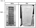
- Fig. 1 is a diagram showing the state before and after an ignition phenomenon of a mesh formed in a conventional battery pack.
- Battery cells mounted on a battery module or a battery pack may generate a large amount of heat during charging and discharging process, and if the temperature is higher than the proper temperature due to reasons such as overcharging, the performance may deteriorate, and excessive temperature rise may cause explosion or ignition.
- the internal materials of the cell may be blown off along with high-temperature flammable gas to the outside of the battery module or battery pack.
- Such internal materials are mainly materials such as C, Cu, Al, Ni, Co, Mg, and Li, and are blown off in the form of high-temperature dusts, i.e., sparks.
- a battery pack comprising: at least one battery module including a plurality of battery cell stacks; a pack frame that houses the battery module; a vent flow path through which gas containing dust generated from the battery module moves; and a final filter that filters the dust before the gas containing the dust is discharged to the outside of the battery pack, wherein the battery pack further comprises a primary filter that is provided at a point where the direction of the vent flow path changes, and primarily filters the dust before the final filter.
- the primary filter may be arranged apart from the inner surface of the vent flow path.
- a first surface of the primary filter may face a first flow path through which the gas flows into the primary filter, and a second surface of the primary filter may face a second flow path through which the gas flows out of the primary filter.
- the orientation of the first surface of the primary filter may be parallel to the direction of the first flow path through which the gas flows into the primary filter, and the orientation of the second surface of the primary filter may be parallel to the direction of the second flow path through which the gas flows out of the primary filter.
- the primary filter comprises at least one plate-shaped filter, wherein the flat surface of the plate-shaped filter may face a first flow path through which the gas flows into the primary filter, and an edge part of the plate-shaped filter may face a second flow path through which the gas flows out of the primary filter.
- the primary filter may comprise a plurality of plate-shaped filters arranged in parallel.
- the first filter arranged closest to the first flow path may be in a most loosening non-dense state, and the plurality of plate-shaped filters may consist of filters that become gradually dense in the order in which they are arranged.
- the primary filter comprises 'n' number of filters arranged in parallel, and the first filter closest to the first flow path may be coarsest, and the kth filter may be denser than the k-1st filter, wherein k is a natural number from 1 to n.
- the plurality of plate-shaped filters each comprises an opening part, and the opening parts of mutually adjacent primary filters may be arranged to cross each other.
- the primary filter may consist of a mesh structure.
- the primary filter may consist of a wavy mesh structure, and the dust may be filtered at the wavy bent part.
- the primary filter may be a resin filter having a porous structure.
- vent flow path may be integrated into the interior of the pack frame.
- the primary filter may be provided at a corner part of the pack frame.
- the primary filter may have a concave structure between both ends, in which both ends protrude toward the first flow path through which the gas flows into the primary filter, and may have an open structure when viewed from the second flow path through which the gas flows out of the primary filter.
- the primary filter has a U-shaped or V-shaped cross section when viewed from the second flow path.
- the primary filter may be provided in plural numbers along a direction perpendicular to each of the first flow path and the second flow path.
- the battery pack may further comprise a first support member that protrudes toward the first flow path so as to support at least both ends of the primary filter.
- the battery pack may further comprise a second support member that connects the first support members provided in at least both ends of the primary filter.
- a device comprising at least one battery pack described above.
- the battery pack of the present disclosure is provided with a primary filter, which can thus more effectively prevent dust from being released to the outside of the battery pack and also can prevent the clogging of the venting flow path.
- upper surface/lower surface of a specific member can be determined differently depending on which direction is used as a reference, throughout the description, 'upper surface' or 'lower surface' is defined as meaning two facing surfaces on the z-axis of the corresponding member.
- planar it means when a target portion is viewed from the upper side
- cross-sectional it means when a target portion is viewed from the side of a cross section cut vertically.
- Fig. 2 is a perspective view of a battery pack according to an embodiment of the present disclosure.
- Fig. 3 is a perspective view of a battery module included in the battery pack according to Fig. 2 .
- Fig. 4 is a top view of the battery pack according to Fig. 2 .
- Fig. 5 is a partial cross-sectional view of the battery pack according to Fig. 2 .
- Fig. 5 may be a cross section of a part of the battery pack taken along the yz plane.
- the battery pack 1000 may comprise at least one battery module 100, a pack frame 200 that houses at least one battery module 100 and a vent flow path 300 formed between the battery module 100 and the pack frame 200.
- the battery module 100 may include a battery cell stack constituted by stacking a plurality of battery cells, a module frame 120 that houses the battery cell stack, a busbar frame that is located on a front surface and/or a rear surface of the battery cell stack, a busbar and/or a sensing unit that are mounted on the busbar frame, and the like.
- the components included in the battery module 100 are not limited thereto, and depending on the design, the battery module 100 may be provided in such a state that some of the above components are omitted, or may be provided in such a state that other components not mentioned are added.
- the type of battery cells included in the battery module 100 is not particularly limited, and pouch-type, prismatic, or jelly-roll type cylindrical battery cells can all be applied.
- the module frame 120 may include a metal having high thermal conductivity.
- the metal may be aluminum, gold, silver, copper, platinum or an alloy containing them. As the thermal conductivity of the metal is higher, the heat dissipation effect by the module frame improves, so that no specific range for thermal conductivity values is set.
- an opening part 130 may be located on one surface of the module frame 120.
- the opening part 130 can be for discharging gas, sparks, flame, or the like within the module frame 120.
- One surface of the module frame 120 on which the opening part 130 is formed may be a surface facing the electrode lead of the battery cell stack, the busbar frame, or the busbar.
- the shape of the opening part 130 may be varied, and as an example, it may have an opening shape.
- the opening part 130 may be in the form of a plate that is broken at a predetermined pressure or higher, such as a rupture disc.
- it may be in the form of a valve that can be opened at a predetermined pressure or higher, such as a relief valve.
- a plurality of battery modules 100 may be provided in the battery pack 1000.
- the plurality of battery modules 100 may be arranged in rows and columns within the pack frame 200.
- Figs. 2 and 4 show a case where a plurality of battery modules 100 are stacked in a lateral direction (x-axis direction of Fig. 4 ) of the pack frame 200, and a plurality of battery modules 100 are stacked in two rows, but the present disclosure is not limited to those described above, and can be stacked in various arrangements.
- the pack frame 200 can be for protecting the battery module 100 and electrical components connected thereto from external physical impact.
- the pack frame 200 may include a lower frame including a lower surface (bottom surface) and a side surface.
- the battery modules 100 are arranged in the inner space of the lower frame formed from the lower surface and the side surface, and then the upper plate or upper frame is coupled with the edge of the lower frame, thereby capable of sealing the pack frame 200.
- the upper plate or upper frame may be interpreted as being included in the pack frame 200, but this is not necessarily the case.
- the pack frame 200 may include a portion having high thermal conductivity in order to quickly dissipate heat generated in the internal space to the outside.
- the pack frame 200 may be made from a metal having high thermal conductivity, and examples thereof may be aluminum, gold, silver, copper, platinum, an alloy containing these, or the like.
- the pack frame 200 may partially have electrical insulation, and an insulating film may be provided at a position where insulation is required, or an insulating coating may be applied.
- a portion of the pack frame 200 to which an insulating film or an insulating coating is applied may be referred to as an insulating portion.
- the vent flow path 300 may be for discharging gas or the like generated from the battery module 100 to the outside of the battery pack 1000.
- the vent flow path 300 may be integrated into the interior of the pack frame 200.
- the vent flow path 300 may be formed in a separation space between the battery module 100 and the pack frame 200.
- the present disclosure is not limited to those described above, and can be applied even when the vent flow path 300 is provided separately on the outside of the pack frame 200, for example, it is sufficient that the vent flow path 300 has a structure and shape that allows high-temperature gas or the like discharged from the battery module 100 to be discharged to the outside.
- the flame, gas, and the like discharged from each of the battery modules 100 to the vent flow path 300 may move along the vent flow path 300 and be discharged to the outside through an outlet port 210 provided at a point at which the vent flow path 300 is completed.
- the shape of the outlet port 210 may vary. As an example, it may be in the form of an opening provided in the pack frame 200. As another example, the outlet port 210 may be in the form of a valve that can be opened at a predetermined pressure or higher, like a relief valve.
- the vent flow path 300 may be preferably formed to correspond to all battery modules 100 in the battery pack 1000. For example, as shown in Fig.
- the vent flow path 300 may be formed between the battery modules 100 and the pack frame 200 arranged in each row.
- the flame, gas, and the like discharged from the battery modules 100 can move through the vent flow path 300 along the dotted line arrows and be discharged to the outlet port.
- An opening part 130 may be located on one surface of the battery module 100 that contacts the vent flow path 300.
- the opening part 130 of the battery module 100 may be located toward the vent flow path 300.
- the battery module 100 may be arranged so that one surface on which the opening part 130 is formed faces the vent flow path 300.
- the vent flow path 300 may be formed so as to extend along one surface of the pack frame 200 corresponding to the opening part 130.
- the gas, flame, and the like discharged through the opening part130 may be discharged into an empty space, and then moved to the vent flow path 300 located on the upper side of the empty space.
- the vent flow path 300 is provided with a final filter 400.
- the final filter 400 may be provided at a point at which the vent flow path 300 is completed, that is, at the front end of the outlet port 210. High-temperature gases, dust, and the like discharged from the battery module 100 pass through a final filter 400 before passing through the vent flow path 300 and then discharging to the outside via the outlet port 210 provided in the pack frame 200.
- the final filter 400 may be a filter having a mesh structure, or may also be a resin filter, as described in detail below.
- the gas discharged from the battery module 100 passes through the final filter 400 and is discharged to the outside of the pack frame 200, and high-temperature dust, i.e., sparks, may be filtered by the final filter 400 and not discharged to the outside. If the release of high-temperature dust, i.e. sparks, is limited by the final filter 400, the possibility of contact of the sparks with external oxygen is reduced, thereby preventing additional ignition from occurring in components adjacent to the battery pack 200.
- high-temperature dust i.e., sparks
- a primary filter 500 is further provided in a portion of the vent flow path 300, i.e., between the opening part 130 of the module frame 120 corresponding to the starting point of the vent flow path 300 and the final filter 400. That is, the gas and dust discharged from the battery module 100 may first pass through the primary filter 500 before passing through the final filter 400. Accordingly, because the high-temperature dust discharged from the battery module 100 is primarily filtered in the primary filter 500 and finally filtered once again by the final filter 400, it is possible to more effectively prevent the risk of high-temperature dust being discharged to the outside of the pack frame 200. Moreover, it is also possible to prevent the final filter 400 from clogging due to dust.
- the primary filter 500 is located in a portion where the direction of the vent flow path 300 changes.
- the venting passage 300 includes a first flow path section 300a and a second flow path section 300b.
- the first flow path section 300a refers to a flow path through which gas and dust discharged from the battery module 100 flow into the primary filter 500
- the second flow path section 300b refers to a flow path through which gas and dust primarily filtered by the primary filter 500 flow out of the primary filter 500.
- Fig. 5 shows a case where the first flow path section 300a is arranged in a lateral direction of the pack frame 200 (x-axis direction in Fig. 4 ), and the second flow path section 300b is arranged in the longitudinal direction of the pack frame 200 (y-axis direction in Fig. 4 ).
- the four corners of the pack frame 200 of Fig. 4 they can be arranged at an upper end corner and a lower end corner of the side where the outlet port 210 is located (see circular dotted line portion in Fig. 4 ).
- the point where the flow path of the vent flow path 300 changes can be changed or modified, and therefore, it is sufficient that the primary filter 500 is arranged at the point where the flow path of the vent flow path 300 changes, and the present disclosure is not limited to those described above.
- the primary filter 500 is arranged only in a part of the cross section when viewed from a cross section perpendicular to the moving direction of gas and dust in the vent flow path 300. That is, even if the primary filter 500 is located, the vent flow path 300 has an open structure at a cross sectional view.
- the primary filter 500 is arranged apart from the inner surface of the vent flow path 300.
- the primary filter 500 may be arranged separately by a support member (not shown) mounted on the inner surface of the vent flow path 300.
- the support member may be a frame or bar-shaped.
- straight bar may be provided in one or more, or may be provided in a U-shape.
- the support member is manufactured, for example, by a method of folding or bending a single straight bar or frame, a method of joining multiple straight bars or frames, or a method of molding by die casting or the like. It is sufficient that the support member allows the primary filter 500 to be supported apart from the inner surface of the vent flow path 300, whereas it does not clog the vent flow path 300, and the shape or structure of the support member are not limited.
- the cross section of the vent flow path 300 where the primary filter 500 is located still has an open structure, that is, the vent flow path 300 is not clogged, thereby capable of preventing danger such as explosion of the pack frame 200.
- the outer surfaces of the primary filter 500 include a first surface 500a facing the first flow path section 300a and a second surface 500b facing the second flow path section 300b.
- the orientation of the first surface 500a of the primary filter 500 may be parallel to a direction in which gas and dust discharged from the battery module 100 flow into the primary filter 500.
- the other surface of the primary filter 500 faces the second flow path section 300b. That is, the orientation of the other surface of the primary filter 500 may be parallel to a direction in which gas and dust discharged from the battery module 100 flow into the primary filter 500.
- Fig. 6 shows a primary filter 500' according to another embodiment of the present disclosure.
- the primary filter 500' may be provided with at least one plate-shaped filter 500-1, 500-2, 500-k, ... 500-n (where k is a natural number from 1 to n). That is, the primary filter 500' may be composed of a single plate-shaped filter 500-1, or may be composed of a plurality of plate-shaped filters 500-1, 500-2, 500-k, ... 500-n. A plurality of plate-shaped filters 500-1, 500-2, 500-k, ... 500-n may be arranged parallel to each other.
- the plate-shaped filter 500-k also has the first surface 500a and the second surface 500b described above in Fig. 5 .
- the wide flat portion of the plate-shaped filter 500-k is the first surface 500a
- the edge part of the plate-shaped filter 500-k is the second surface 500b. Since the wide flat portion of the plate-shaped filter 500-k faces the first flow path section 300a, dust discharged from the battery module 100 is filtered.
- the edge part of the plate-shaped filter 500-k is viewed, and thus, the primary filter 500' has an open structure.
- the vent flow path 300 is not clogged, and gas and dust discharged from the battery module 100 may flow toward the outlet port 210.
- the plurality of plate-shaped filters 500-1, 500-2, 500-k, ... 500-n are arranged in order from the filter closest to the first flow path section 300a, that is, the first filter 500-1, to the n-th filter 500-n, the first filter 500-1 may be the most loosening non-dense filter, and the last n-th filter 500-n may be the densest filter.
- the first filter 500-1 through which gas and dust discharged from the battery module 100 first pass, is formed in a most loosening non-dense state, and the subsequent filters 500-2, ... 500k, ... 500n become denser in order, thereby capable of preventing the risk of clogging the vent flow path 300 with the filtered dusts.
- gas and dust flowing in from the battery module 100 move along the first flow path section 300a and pass through the primary filter 500 located at a point at which the first flow path section 300a is completed.
- the dust is filtered by the primary filter 500' while passing through the first filter 500-1, which is in a most loosening non-dense state, and passing through subsequent filters 500-2, ... 500k, ... 500n that gradually become denser in order.
- the primary filter 500' is located at the point where the flow path changes, the gas moves to the changed flow path, that is, to the second flow path section 300b.
- the primary filter 500' has an open structure when viewed from the second flow path section 300b, the gas smoothly moves along the second flow path section 300b, and the dust is finally filtered by the final filter 400 at the front end of the outlet port 210, and then is discharged to the outside via the outlet port 210 provided in the pack frame 200.
- the primary filter 500 may be a filter having a mesh structure.
- the mesh structure may be a wavy mesh structure arranged in a plurality of rows.
- mesh structures of various shapes can be adopted, such as a structure woven into a square net shape.
- dust is filtered in the bent part 510 (see Fig. 8 ), and parts other than the bent part are open, so that the gas can move smoothly to the second flow path section 300b without clogging the filter with dust.
- the filter having a mesh structure may be made from a metal material.
- a raw fabric obtained by weaving multifilament fibers such as polyester, nylon, polypropylene, etc. may be coated with a flame-retardant vinyl chloride-based paste resin composition, and then processed into a net shape by heat treatment.
- the primary filter 500 may have a structure including a plurality of suction holes therein.
- the primary filter 500 may be a resin filter having a porous structure that can filter out fine-sized foreign matter.
- the resins used for manufacturing the resin filter include those with excellent heat resistance, such as fluorine resin, polyurethane resin, and epoxy resin.
- the primary filter 500' may include an opening part 520.
- the positions of the opening parts 520-k (where k is a natural number from 1 to n) of the plurality of primary filters 500-k may be arranged so that adjacent primary filters cross each other.
- Fig. 9(a) is a perspective view
- Fig. 9(b) shows a state where a plurality of primary filters are arranged in a row for convenience of explanation.
- the primary filter 500' is a modification of the primary filter 500, and may employ a filter having a mesh structure as described above for the primary filter 500, or may have a structure made of a flame-retardant material, which will be described later. That is, the primary filter 500' has a structure in which an opening part 520 is further added to the primary filter 500 as described above.
- the primary filter 500 may be made of a flame-retardant material that is hardly combustible.
- the flame retardant material may be chlorine-containing vinyl chloride resin, chlorinated paraffin, decabromodiphenyl oxide, antimony trioxide, and the like.
- Fig. 10 is a perspective view which enlarges and shows a portion where the direction of the vent flow path in which the primary filter of Fig. 6 is arranged changes.
- the primary filter 500' is arranged apart from the inner wall of the venting flow path 300 so as not to block the vent flow path 300, and is especially arranged to have an open structure with respect to the second flow path section 300b through which the vent gas escapes.
- Figs. 11 to 13 show another embodiment of the primary filter.
- Fig. 11 exemplarily shows a case where the primary filter 500 is located at a portion where the direction of the vent flow path 300 changes.
- Fig. 12 is an enlarged perspective view of the primary filter 500 of Fig. 11 .
- Fig. 13 is an enlarged perspective view of the primary filter 500 of Fig. 11 as viewed from a different direction.
- illustration of the frame 200 forming the first flow path section 300a and the second flow path section 300b is omitted.
- the primary filter 500 is arranged between the first flow path section 300a and the second flow path section 300b in which the direction of the flow path changes.
- the primary filter 500 is mounted on the support unit 530.
- the support unit 530 includes a first support member 531 that supports at least both end parts of the primary filter 500.
- both end parts of the primary filter 500 refer to both end parts in a direction perpendicular to the extension direction of the first flow path section 300a and the extension direction of the second flow path section 300b, respectively. In the illustration of Fig. 11 , it means an end part in the height direction of the flow path 300.
- the first support member 531 protrudes toward the first flow path section 300a into which vent gas flows.
- the second support member 532 connects between the first support members 531 provided at both ends of the primary filter 500, respectively.
- the second support member 532 may extend in the height direction of the flow path 300, and the second support member 532 supports the primary filter 500, for example, in the height direction.
- the first support member 531 may extend vertically from the second support member 532.
- the first support member 531 protrudes from both ends (upper end and lower end) of the second support member 532, respectively, and supports both ends (upper end and lower end) of the primary filter 500.
- the present disclosure is not limited to those illustrated, and various modifications and changes can be made, such as having a structure in which the first support member 531 protrudes from the inner wall of the flow path 300 without the second support member 532.
- the primary filter 500 can be made, for example, in a sheet shape, and can be made longer than the height between the first support members 531 that support both ends (upper end and lower end) of the primary filter 500.
- the primary filter 500 may have a concave structure and shape toward the first flow path section 300a. More specifically, both ends of the primary filter 500 protrude toward the first flow path section 300a, and a concave structure may be formed between the both ends.
- the cross section seen from the second flow path section 300b may have a U-shape or a V-shape. Accordingly, the primary filter 500 is formed across the first flow path section 300a when viewed from the first flow path section 300a into which the vent gas is drawn, and it becomes an open structure that is not clogged when viewed from the second flow path section 300b.
- the vent gas containing dust and the like abuts on the whole area of the primary filter 500 from the first flow path section 300a, and the dust, and the like is filtered, and the vent gas moves to the second flow path section 300b, which is the direction in which the primary filter 500 is opened.
- the second flow path section 300b has an open shape due to the structure of the primary filter 500, which makes it possible to avoid a situation where the primary filter 500 clogged with dust blocks the flow path 300.
- Fig. 11 exemplarily shows a case where the primary filter 500 has a U-shaped cross section. In some cases, a portion of the primary filter 500 except the upper end and the lower end may be bonded to the second support member 532.
- Fig. 11 shows a case in which a plurality of primary filters 500 each having a U-shaped cross section are provided in the up and down direction. That is, a plurality of primary filters 500-1 and 500-2 may be provided along a direction perpendicular to each of the extending directions of the first flow path section 300a and the extending direction of the second flow path section 300b. At this time, both ends of each of the plurality of primary filters 500-1 and 500-2 may be connected to each other.
- the battery pack may further include a battery management system (BMS) and/or a cooling device that controls and manages battery's temperature, voltage, etc.
- BMS battery management system
- the battery pack according to one embodiment of the present disclosure can be applied to various devices.
- the device to which the battery pack is applied may be a vehicle means such as an electric bicycle, an electric vehicle, or a hybrid vehicle, but the above-mentioned device is not limited thereto, and the battery pack according to the present embodiment can be used for various devices in addition to the above illustrations, which also falls within the scope of the present disclosure.
Landscapes
- Chemical & Material Sciences (AREA)
- Chemical Kinetics & Catalysis (AREA)
- Electrochemistry (AREA)
- General Chemical & Material Sciences (AREA)
- Engineering & Computer Science (AREA)
- Aviation & Aerospace Engineering (AREA)
- Gas Exhaust Devices For Batteries (AREA)
- Battery Mounting, Suspending (AREA)
Abstract
Description
- This application claims priority benefit of
Korean Patent Application No. 10-2022-0084941, filed on July 11, 2022 Korean Patent Application No. 10-2023-0089362, filed on July 10, 2023 - The present disclosure relates to a battery pack and a device including the same, and more particularly, to a battery pack that can prevent external ignition phenomena and prevent the clogging of the vent flow path, and a device including the same.
- In modern society, as portable devices such as a mobile phone, a notebook computer, a camcorder and a digital camera have been daily used, the development of technologies in the fields related to mobile devices as described above has been activated. In addition, chargeable/dischargeable secondary batteries are used as a power source for an electric vehicle (EV), a hybrid electric vehicle (HEV), a plug-in hybrid electric vehicle (P-HEV) and the like, in an attempt to solve air pollution and the like caused by existing gasoline vehicles using fossil fuel. Therefore, the demand for development of the secondary battery is growing.
- Currently commercialized secondary batteries include a nickel cadmium battery, a nickel hydrogen battery, a nickel zinc battery, a lithium secondary battery, and the like. Among them, the lithium secondary battery has come into the spotlight because it has advantages, for example, being freely charged and discharged, and having very low self-discharge rate and high energy density.
- Meanwhile, in the case of a secondary battery used for small-sized devices, two to three battery cells are used, but in the case of a secondary battery used for a medium- and large-sized device such as automobiles, a medium- or large-sized battery module in which a large number of battery cells are electrically connected is used.
-
Fig. 1 is a diagram showing the state before and after an ignition phenomenon of a mesh formed in a conventional battery pack. - Battery cells mounted on a battery module or a battery pack may generate a large amount of heat during charging and discharging process, and if the temperature is higher than the proper temperature due to reasons such as overcharging, the performance may deteriorate, and excessive temperature rise may cause explosion or ignition. When the battery cell ignites, the internal materials of the cell may be blown off along with high-temperature flammable gas to the outside of the battery module or battery pack. Such internal materials are mainly materials such as C, Cu, Al, Ni, Co, Mg, and Li, and are blown off in the form of high-temperature dusts, i.e., sparks.
- On the other hand, such sparks not only promote cascading thermal runaway phenomena within the battery module or battery pack, but also have the problem of causing external ignition phenomena by contacting with flammable gas or external oxygen when discharged to the outside. Therefore, in recent years, attempts have been made to form a mesh on the frame of a battery module or battery pack to minimize the release of dust.
- However, even if a mesh is formed on the frame, the release of internal gas is restricted if dust closes the opening of the mesh as shown in
Fig. 1 , whereby the internal pressure of the battery module or pack increases rapidly, which can lead to explosions and frame damage. Therefore, there is a need for an effective frame structure that limits sparks from being released to the outside of the frame. - It is an object of the present disclosure to provide a battery pack having improved durability and safety by preventing external ignition phenomena caused by sparks, and a device including the same.
- However, the technical problems to be solved by embodiments of the present disclosure are not limited to the technical problems described above, and can be variously expanded within the scope of the technical idea included in the present disclosure.
- According to an embodiment of the present disclosure, there can be provided a battery pack comprising: at least one battery module including a plurality of battery cell stacks; a pack frame that houses the battery module; a vent flow path through which gas containing dust generated from the battery module moves; and a final filter that filters the dust before the gas containing the dust is discharged to the outside of the battery pack, wherein the battery pack further comprises a primary filter that is provided at a point where the direction of the vent flow path changes, and primarily filters the dust before the final filter.
- The primary filter may be arranged apart from the inner surface of the vent flow path.
- A first surface of the primary filter may face a first flow path through which the gas flows into the primary filter, and a second surface of the primary filter may face a second flow path through which the gas flows out of the primary filter.
- The orientation of the first surface of the primary filter may be parallel to the direction of the first flow path through which the gas flows into the primary filter, and the orientation of the second surface of the primary filter may be parallel to the direction of the second flow path through which the gas flows out of the primary filter.
- The primary filter comprises at least one plate-shaped filter, wherein the flat surface of the plate-shaped filter may face a first flow path through which the gas flows into the primary filter, and an edge part of the plate-shaped filter may face a second flow path through which the gas flows out of the primary filter.
- The primary filter may comprise a plurality of plate-shaped filters arranged in parallel.
- The first filter arranged closest to the first flow path may be in a most loosening non-dense state, and the plurality of plate-shaped filters may consist of filters that become gradually dense in the order in which they are arranged.
- The primary filter comprises 'n' number of filters arranged in parallel, and the first filter closest to the first flow path may be coarsest, and the kth filter may be denser than the k-1st filter, wherein k is a natural number from 1 to n.
- The plurality of plate-shaped filters each comprises an opening part, and the opening parts of mutually adjacent primary filters may be arranged to cross each other.
- The primary filter may consist of a mesh structure.
- The primary filter may consist of a wavy mesh structure, and the dust may be filtered at the wavy bent part.
- The primary filter may be a resin filter having a porous structure.
- The vent flow path may be integrated into the interior of the pack frame.
- The primary filter may be provided at a corner part of the pack frame.
- The primary filter may have a concave structure between both ends, in which both ends protrude toward the first flow path through which the gas flows into the primary filter, and may have an open structure when viewed from the second flow path through which the gas flows out of the primary filter.
- The primary filter has a U-shaped or V-shaped cross section when viewed from the second flow path.
- The primary filter may be provided in plural numbers along a direction perpendicular to each of the first flow path and the second flow path.
- The battery pack may further comprise a first support member that protrudes toward the first flow path so as to support at least both ends of the primary filter.
- The battery pack may further comprise a second support member that connects the first support members provided in at least both ends of the primary filter.
- According to another embodiment of the present disclosure, there is provided a device comprising at least one battery pack described above.
- According to the embodiments, the battery pack of the present disclosure is provided with a primary filter, which can thus more effectively prevent dust from being released to the outside of the battery pack and also can prevent the clogging of the venting flow path.
- The effects of the present disclosure are not limited to the effects mentioned above, and additional other effects not mentioned above will be clearly understood from the description of claims by those skilled in the art.
-
-
Fig. 1 is a diagram showing the state before and after an ignition phenomenon of a mesh formed in a conventional battery pack; -
Fig. 2 is a perspective view of a battery pack according to an embodiment of the present disclosure; -
Fig. 3 is a perspective view of a battery module included in the battery pack according toFig. 2 ; -
Fig. 4 is a top view of the battery pack according toFig. 2 ; -
Fig. 5 shows an embodiment of the present disclosure, and is a partial cross-sectional view enlarging and showing a portion where the primary filter is provided in the battery pack shown inFig. 4 ; -
Fig. 6 shows another embodiment of the present disclosure in which the primary filter ofFig. 5 is modified; -
Fig. 7 is a perspective view of one embodiment of the primary filter ofFig. 6 ; -
Fig. 8 is a partial enlarged view of the primary filter ofFig. 7 , showing a case where dust is filtered out at a bent part; -
Fig. 9 is a perspective view of another embodiment of the primary filter ofFig. 6 ; -
Fig. 10 is a perspective view which enlarges and shows a portion where the direction of the vent flow path in which the primary filter ofFig. 6 is arranged changes; -
Fig. 11 shows another embodiment of the primary filter; -
Fig. 12 is an enlarged perspective view of the primary filter ofFig. 11 ; and -
Fig. 13 is an enlarged perspective view of the primary filter ofFig. 11 as viewed from a different direction. - Hereinafter, various embodiments of the present disclosure will be described in detail with reference to the accompanying drawings so that those skilled in the art can easily carry out them. The present disclosure can be modified in various different ways, and is not limited to the embodiments set forth herein.
- Portions that are irrelevant to the description will be omitted to clearly describe the present disclosure, and like reference numerals designate like elements throughout the description.
- Further, since the size and thickness of each element shown in the accompanying drawing are arbitrarily illustrated for convenience of explanation, it would be obvious that the present disclosure is not necessarily limited to those illustrated in the drawings. In the drawings, the thickness are exaggerated for clearly expressing several layers and regions. In the drawings, for convenience of explanation, the thicknesses of some layer and regions are exaggerated.
- Further, it will be understood that when an element such as a layer, film, region, or plate is referred to as being formed or disposed "on" or "above" another element, it should be interpreted as including not only a case where an element such as a layer, film, region, or plate is directly on the other element but also a case where intervening elements are present. In contrast, when an element such as a layer, film, region, or plate is referred to as being formed or disposed "directly on" another element, it may mean that other intervening elements are not present. Further, the word "on" or "above" means disposed on or below a reference portion, and does not necessarily mean being disposed on the upper end of the reference portion toward the opposite direction of gravity. Meanwhile, similar to the case where it is described as being formed or disposed "on" or "above" another part, the case where it is described as being formed or disposed "below" or "under" another part will also be understood with reference to the above-mentioned contents.
- Further, since the upper surface/lower surface of a specific member can be determined differently depending on which direction is used as a reference, throughout the description, 'upper surface' or 'lower surface' is defined as meaning two facing surfaces on the z-axis of the corresponding member.
- Further, throughout the description, when a portion is referred to as "including" or "comprising" a certain component, it means that the portion can further include other components, without excluding the other components, unless otherwise stated.
- Further, throughout the description, when it is referred to as "planar", it means when a target portion is viewed from the upper side, and when it is referred to as "cross-sectional", it means when a target portion is viewed from the side of a cross section cut vertically.
- Now, a battery pack according to an embodiment of the present disclosure will be described.
-
Fig. 2 is a perspective view of a battery pack according to an embodiment of the present disclosure.Fig. 3 is a perspective view of a battery module included in the battery pack according toFig. 2 .Fig. 4 is a top view of the battery pack according toFig. 2 .Fig. 5 is a partial cross-sectional view of the battery pack according toFig. 2 .Fig. 5 may be a cross section of a part of the battery pack taken along the yz plane. - Referring to
Figs. 2 to 5 , thebattery pack 1000 according to an embodiment of the present disclosure may comprise at least onebattery module 100, apack frame 200 that houses at least onebattery module 100 and avent flow path 300 formed between thebattery module 100 and thepack frame 200. - The
battery module 100 according to the present embodiment may include a battery cell stack constituted by stacking a plurality of battery cells, amodule frame 120 that houses the battery cell stack, a busbar frame that is located on a front surface and/or a rear surface of the battery cell stack, a busbar and/or a sensing unit that are mounted on the busbar frame, and the like. However, the components included in thebattery module 100 are not limited thereto, and depending on the design, thebattery module 100 may be provided in such a state that some of the above components are omitted, or may be provided in such a state that other components not mentioned are added. The type of battery cells included in thebattery module 100 is not particularly limited, and pouch-type, prismatic, or jelly-roll type cylindrical battery cells can all be applied. - The
module frame 120 may include a metal having high thermal conductivity. Examples of the metal may be aluminum, gold, silver, copper, platinum or an alloy containing them. As the thermal conductivity of the metal is higher, the heat dissipation effect by the module frame improves, so that no specific range for thermal conductivity values is set. - Meanwhile, an
opening part 130 may be located on one surface of themodule frame 120. When thebattery module 100 ignites, theopening part 130 can be for discharging gas, sparks, flame, or the like within themodule frame 120. One surface of themodule frame 120 on which theopening part 130 is formed may be a surface facing the electrode lead of the battery cell stack, the busbar frame, or the busbar. - The shape of the
opening part 130 may be varied, and as an example, it may have an opening shape. As another example, theopening part 130 may be in the form of a plate that is broken at a predetermined pressure or higher, such as a rupture disc. As yet another example, it may be in the form of a valve that can be opened at a predetermined pressure or higher, such as a relief valve. - As shown in
Figs. 2 and4 , a plurality ofbattery modules 100 may be provided in thebattery pack 1000. The plurality ofbattery modules 100 may be arranged in rows and columns within thepack frame 200.Figs. 2 and4 show a case where a plurality ofbattery modules 100 are stacked in a lateral direction (x-axis direction ofFig. 4 ) of thepack frame 200, and a plurality ofbattery modules 100 are stacked in two rows, but the present disclosure is not limited to those described above, and can be stacked in various arrangements. - The
pack frame 200 according to the present embodiment can be for protecting thebattery module 100 and electrical components connected thereto from external physical impact. Thepack frame 200 may include a lower frame including a lower surface (bottom surface) and a side surface. Thebattery modules 100 are arranged in the inner space of the lower frame formed from the lower surface and the side surface, and then the upper plate or upper frame is coupled with the edge of the lower frame, thereby capable of sealing thepack frame 200. Here, the upper plate or upper frame may be interpreted as being included in thepack frame 200, but this is not necessarily the case. - The
pack frame 200 may include a portion having high thermal conductivity in order to quickly dissipate heat generated in the internal space to the outside. For example, at least a part of thepack frame 200 may be made from a metal having high thermal conductivity, and examples thereof may be aluminum, gold, silver, copper, platinum, an alloy containing these, or the like. Moreover, thepack frame 200 may partially have electrical insulation, and an insulating film may be provided at a position where insulation is required, or an insulating coating may be applied. A portion of thepack frame 200 to which an insulating film or an insulating coating is applied may be referred to as an insulating portion. - The
vent flow path 300 may be for discharging gas or the like generated from thebattery module 100 to the outside of thebattery pack 1000. Thevent flow path 300 may be integrated into the interior of thepack frame 200. In this case, thevent flow path 300 may be formed in a separation space between thebattery module 100 and thepack frame 200. However, the present disclosure is not limited to those described above, and can be applied even when thevent flow path 300 is provided separately on the outside of thepack frame 200, for example, it is sufficient that thevent flow path 300 has a structure and shape that allows high-temperature gas or the like discharged from thebattery module 100 to be discharged to the outside. - The flame, gas, and the like discharged from each of the
battery modules 100 to thevent flow path 300 may move along thevent flow path 300 and be discharged to the outside through anoutlet port 210 provided at a point at which thevent flow path 300 is completed. The shape of theoutlet port 210 may vary. As an example, it may be in the form of an opening provided in thepack frame 200. As another example, theoutlet port 210 may be in the form of a valve that can be opened at a predetermined pressure or higher, like a relief valve. Thevent flow path 300 may be preferably formed to correspond to allbattery modules 100 in thebattery pack 1000. For example, as shown inFig. 4 , when thebattery modules 100 are arranged in two rows and four columns, thevent flow path 300 may be formed between thebattery modules 100 and thepack frame 200 arranged in each row. The flame, gas, and the like discharged from thebattery modules 100 can move through thevent flow path 300 along the dotted line arrows and be discharged to the outlet port. - An
opening part 130 may be located on one surface of thebattery module 100 that contacts thevent flow path 300. Theopening part 130 of thebattery module 100 may be located toward thevent flow path 300. Thebattery module 100 may be arranged so that one surface on which theopening part 130 is formed faces thevent flow path 300. As shown inFig. 4 , when thevent flow path 300 is formed along the edge of thepack frame 200, thebattery module 100 may be arranged so that theopening part 130 is located toward thepack frame 200. Thevent flow path 300 may be formed so as to extend along one surface of thepack frame 200 corresponding to theopening part 130. The gas, flame, and the like discharged through the opening part130 may be discharged into an empty space, and then moved to thevent flow path 300 located on the upper side of the empty space. - On the other hand, referring to
Fig. 6 , thevent flow path 300 is provided with afinal filter 400. As an example, thefinal filter 400 may be provided at a point at which thevent flow path 300 is completed, that is, at the front end of theoutlet port 210. High-temperature gases, dust, and the like discharged from thebattery module 100 pass through afinal filter 400 before passing through thevent flow path 300 and then discharging to the outside via theoutlet port 210 provided in thepack frame 200. Thefinal filter 400 may be a filter having a mesh structure, or may also be a resin filter, as described in detail below. - The gas discharged from the
battery module 100 passes through thefinal filter 400 and is discharged to the outside of thepack frame 200, and high-temperature dust, i.e., sparks, may be filtered by thefinal filter 400 and not discharged to the outside. If the release of high-temperature dust, i.e. sparks, is limited by thefinal filter 400, the possibility of contact of the sparks with external oxygen is reduced, thereby preventing additional ignition from occurring in components adjacent to thebattery pack 200. - In addition, a
primary filter 500 is further provided in a portion of thevent flow path 300, i.e., between the openingpart 130 of themodule frame 120 corresponding to the starting point of thevent flow path 300 and thefinal filter 400. That is, the gas and dust discharged from thebattery module 100 may first pass through theprimary filter 500 before passing through thefinal filter 400. Accordingly, because the high-temperature dust discharged from thebattery module 100 is primarily filtered in theprimary filter 500 and finally filtered once again by thefinal filter 400, it is possible to more effectively prevent the risk of high-temperature dust being discharged to the outside of thepack frame 200. Moreover, it is also possible to prevent thefinal filter 400 from clogging due to dust. - According to the present disclosure, the
primary filter 500 is located in a portion where the direction of thevent flow path 300 changes. Theventing passage 300 includes a firstflow path section 300a and a secondflow path section 300b. The firstflow path section 300a refers to a flow path through which gas and dust discharged from thebattery module 100 flow into theprimary filter 500, and the secondflow path section 300b refers to a flow path through which gas and dust primarily filtered by theprimary filter 500 flow out of theprimary filter 500. -
Fig. 5 shows a case where the firstflow path section 300a is arranged in a lateral direction of the pack frame 200 (x-axis direction inFig. 4 ), and the secondflow path section 300b is arranged in the longitudinal direction of the pack frame 200 (y-axis direction inFig. 4 ). In this embodiment ofFig. 5 , among the four corners of thepack frame 200 ofFig. 4 , they can be arranged at an upper end corner and a lower end corner of the side where theoutlet port 210 is located (see circular dotted line portion inFig. 4 ). - On the other hand, depending on the stacking direction of the
battery module 100, the structure and shape of thevent flow path 300, the positional change of theoutlet port 210, or the like, the point where the flow path of thevent flow path 300 changes can be changed or modified, and therefore, it is sufficient that theprimary filter 500 is arranged at the point where the flow path of thevent flow path 300 changes, and the present disclosure is not limited to those described above. - Further, according to the present disclosure, in order to prevent the clogging of the
vent flow path 300, theprimary filter 500 is arranged only in a part of the cross section when viewed from a cross section perpendicular to the moving direction of gas and dust in thevent flow path 300. That is, even if theprimary filter 500 is located, thevent flow path 300 has an open structure at a cross sectional view. In other words, theprimary filter 500 is arranged apart from the inner surface of thevent flow path 300. For this purpose, theprimary filter 500 may be arranged separately by a support member (not shown) mounted on the inner surface of thevent flow path 300. The support member may be a frame or bar-shaped. For example, straight bar may be provided in one or more, or may be provided in a U-shape. The support member is manufactured, for example, by a method of folding or bending a single straight bar or frame, a method of joining multiple straight bars or frames, or a method of molding by die casting or the like. It is sufficient that the support member allows theprimary filter 500 to be supported apart from the inner surface of thevent flow path 300, whereas it does not clog thevent flow path 300, and the shape or structure of the support member are not limited. - Even if the
primary filter 500 is clogged by accumulating dust in theprimary filter 500, the cross section of thevent flow path 300 where theprimary filter 500 is located still has an open structure, that is, thevent flow path 300 is not clogged, thereby capable of preventing danger such as explosion of thepack frame 200. - Further, according to the present disclosure, the outer surfaces of the
primary filter 500 include a first surface 500a facing the firstflow path section 300a and a second surface 500b facing the secondflow path section 300b. At this time, the orientation of the first surface 500a of theprimary filter 500 may be parallel to a direction in which gas and dust discharged from thebattery module 100 flow into theprimary filter 500. On the other hand, the other surface of theprimary filter 500 faces the secondflow path section 300b. That is, the orientation of the other surface of theprimary filter 500 may be parallel to a direction in which gas and dust discharged from thebattery module 100 flow into theprimary filter 500. -
Fig. 6 shows a primary filter 500' according to another embodiment of the present disclosure. In the embodiments ofFigs. 6 and7 , the primary filter 500' may be provided with at least one plate-shaped filter 500-1, 500-2, 500-k, ... 500-n (where k is a natural number from 1 to n). That is, the primary filter 500' may be composed of a single plate-shaped filter 500-1, or may be composed of a plurality of plate-shaped filters 500-1, 500-2, 500-k, ... 500-n. A plurality of plate-shaped filters 500-1, 500-2, 500-k, ... 500-n may be arranged parallel to each other. - The plate-shaped filter 500-k also has the first surface 500a and the second surface 500b described above in
Fig. 5 . For the definitions of the first surface 500a and the second surface 500b, refer to the contents described above inFig. 5 . At this time, the wide flat portion of the plate-shaped filter 500-k is the first surface 500a, and the edge part of the plate-shaped filter 500-k is the second surface 500b. Since the wide flat portion of the plate-shaped filter 500-k faces the firstflow path section 300a, dust discharged from thebattery module 100 is filtered. On the other hand, when looking at the primary filter 500' from the secondflow path section 300b, the edge part of the plate-shaped filter 500-k is viewed, and thus, the primary filter 500' has an open structure. Therefore, even if the filtering function is lost as the primary filter 500' performs some filtering, due to this open structure, thevent flow path 300 is not clogged, and gas and dust discharged from thebattery module 100 may flow toward theoutlet port 210. On the other hand, the plurality of plate-shaped filters 500-1, 500-2, 500-k, ... 500-n are arranged in order from the filter closest to the firstflow path section 300a, that is, the first filter 500-1, to the n-th filter 500-n, the first filter 500-1 may be the most loosening non-dense filter, and the last n-th filter 500-n may be the densest filter. The first filter 500-1, through which gas and dust discharged from thebattery module 100 first pass, is formed in a most loosening non-dense state, and the subsequent filters 500-2, ... 500k, ... 500n become denser in order, thereby capable of preventing the risk of clogging thevent flow path 300 with the filtered dusts. - In summary, gas and dust flowing in from the
battery module 100 move along the firstflow path section 300a and pass through theprimary filter 500 located at a point at which the firstflow path section 300a is completed. At this time, due to the straight-line nature (inertia) of gas and dust, the dust is filtered by the primary filter 500' while passing through the first filter 500-1, which is in a most loosening non-dense state, and passing through subsequent filters 500-2, ... 500k, ... 500n that gradually become denser in order. On the other hand, because the primary filter 500' is located at the point where the flow path changes, the gas moves to the changed flow path, that is, to the secondflow path section 300b. At this time, since the primary filter 500' has an open structure when viewed from the secondflow path section 300b, the gas smoothly moves along the secondflow path section 300b, and the dust is finally filtered by thefinal filter 400 at the front end of theoutlet port 210, and then is discharged to the outside via theoutlet port 210 provided in thepack frame 200. - The
primary filter 500 may be a filter having a mesh structure. As shown inFig. 7 , the mesh structure may be a wavy mesh structure arranged in a plurality of rows. Alternatively, mesh structures of various shapes can be adopted, such as a structure woven into a square net shape. In the case of a wavy mesh structure, dust is filtered in the bent part 510 (seeFig. 8 ), and parts other than the bent part are open, so that the gas can move smoothly to the secondflow path section 300b without clogging the filter with dust. - The filter having a mesh structure may be made from a metal material. Alternatively, a raw fabric obtained by weaving multifilament fibers such as polyester, nylon, polypropylene, etc. may be coated with a flame-retardant vinyl chloride-based paste resin composition, and then processed into a net shape by heat treatment.
- Further, the
primary filter 500 may have a structure including a plurality of suction holes therein. In this case, theprimary filter 500 may be a resin filter having a porous structure that can filter out fine-sized foreign matter. The resins used for manufacturing the resin filter include those with excellent heat resistance, such as fluorine resin, polyurethane resin, and epoxy resin. - On the other hand, as shown in
Fig. 9 , the primary filter 500' may include anopening part 520. When looking at the primary filter from the firstflow path section 300a, the positions of the opening parts 520-k (where k is a natural number from 1 to n) of the plurality of primary filters 500-k may be arranged so that adjacent primary filters cross each other.Fig. 9(a) is a perspective view, andFig. 9(b) shows a state where a plurality of primary filters are arranged in a row for convenience of explanation. - Additionally, the primary filter 500' is a modification of the
primary filter 500, and may employ a filter having a mesh structure as described above for theprimary filter 500, or may have a structure made of a flame-retardant material, which will be described later. That is, the primary filter 500' has a structure in which anopening part 520 is further added to theprimary filter 500 as described above. - Meanwhile, the
primary filter 500 may be made of a flame-retardant material that is hardly combustible. For example, the flame retardant material may be chlorine-containing vinyl chloride resin, chlorinated paraffin, decabromodiphenyl oxide, antimony trioxide, and the like. -
Fig. 10 is a perspective view which enlarges and shows a portion where the direction of the vent flow path in which the primary filter ofFig. 6 is arranged changes. As shown inFigs. 6 and10 , the primary filter 500' is arranged apart from the inner wall of the ventingflow path 300 so as not to block thevent flow path 300, and is especially arranged to have an open structure with respect to the secondflow path section 300b through which the vent gas escapes. -
Figs. 11 to 13 show another embodiment of the primary filter.Fig. 11 exemplarily shows a case where theprimary filter 500 is located at a portion where the direction of thevent flow path 300 changes.Fig. 12 is an enlarged perspective view of theprimary filter 500 ofFig. 11 .Fig. 13 is an enlarged perspective view of theprimary filter 500 ofFig. 11 as viewed from a different direction. InFigs. 12 and13 , for convenience of understanding, illustration of theframe 200 forming the firstflow path section 300a and the secondflow path section 300b is omitted. - Referring to
Fig. 11 , theprimary filter 500 is arranged between the firstflow path section 300a and the secondflow path section 300b in which the direction of the flow path changes. Theprimary filter 500 is mounted on thesupport unit 530. Thesupport unit 530 includes afirst support member 531 that supports at least both end parts of theprimary filter 500. Here, both end parts of theprimary filter 500 refer to both end parts in a direction perpendicular to the extension direction of the firstflow path section 300a and the extension direction of the secondflow path section 300b, respectively. In the illustration ofFig. 11 , it means an end part in the height direction of theflow path 300. - The
first support member 531 protrudes toward the firstflow path section 300a into which vent gas flows. Thesecond support member 532 connects between thefirst support members 531 provided at both ends of theprimary filter 500, respectively. For example, thesecond support member 532 may extend in the height direction of theflow path 300, and thesecond support member 532 supports theprimary filter 500, for example, in the height direction. Thefirst support member 531 may extend vertically from thesecond support member 532. Further, thefirst support member 531 protrudes from both ends (upper end and lower end) of thesecond support member 532, respectively, and supports both ends (upper end and lower end) of theprimary filter 500. On the other hand, the present disclosure is not limited to those illustrated, and various modifications and changes can be made, such as having a structure in which thefirst support member 531 protrudes from the inner wall of theflow path 300 without thesecond support member 532. - The
primary filter 500 can be made, for example, in a sheet shape, and can be made longer than the height between thefirst support members 531 that support both ends (upper end and lower end) of theprimary filter 500. Theprimary filter 500 may have a concave structure and shape toward the firstflow path section 300a. More specifically, both ends of theprimary filter 500 protrude toward the firstflow path section 300a, and a concave structure may be formed between the both ends. At this time, when viewed from the secondflow path section 300b through which the vent gas flows out, it has an open shape. For example, the cross section seen from the secondflow path section 300b may have a U-shape or a V-shape. Accordingly, theprimary filter 500 is formed across the firstflow path section 300a when viewed from the firstflow path section 300a into which the vent gas is drawn, and it becomes an open structure that is not clogged when viewed from the secondflow path section 300b. - Accordingly, the vent gas containing dust and the like abuts on the whole area of the
primary filter 500 from the firstflow path section 300a, and the dust, and the like is filtered, and the vent gas moves to the secondflow path section 300b, which is the direction in which theprimary filter 500 is opened. At this time, even if theprimary filter 500 is clogged (even if the filtering function is almost lost) due to the continued filtering in theprimary filter 500, the secondflow path section 300b has an open shape due to the structure of theprimary filter 500, which makes it possible to avoid a situation where theprimary filter 500 clogged with dust blocks theflow path 300. -
Fig. 11 exemplarily shows a case where theprimary filter 500 has a U-shaped cross section. In some cases, a portion of theprimary filter 500 except the upper end and the lower end may be bonded to thesecond support member 532. - Further,
Fig. 11 shows a case in which a plurality ofprimary filters 500 each having a U-shaped cross section are provided in the up and down direction. That is, a plurality of primary filters 500-1 and 500-2 may be provided along a direction perpendicular to each of the extending directions of the firstflow path section 300a and the extending direction of the secondflow path section 300b. At this time, both ends of each of the plurality of primary filters 500-1 and 500-2 may be connected to each other. - For example, not only the upper and lower ends of the
primary filter 500 but also the central part may be supported by thefirst support member 531. Accordingly, a plurality of U-shapedprimary filters 500 are provided in the extending direction (for example, in the up and down direction) of thesecond support member 532, exemplarily showing a case where theprimary filter 500 has a "3" shape as a whole. On the other hand, the present disclosure is not limited to those illustrated, and various modifications and changes can be made, such as providing three or moreprimary filters 500 having a U-shaped or V-shaped concave shape. On the other hand, although not specifically mentioned above, the battery pack according to one embodiment of the present disclosure may further include a battery management system (BMS) and/or a cooling device that controls and manages battery's temperature, voltage, etc. - The battery pack according to one embodiment of the present disclosure can be applied to various devices. For example, the device to which the battery pack is applied may be a vehicle means such as an electric bicycle, an electric vehicle, or a hybrid vehicle, but the above-mentioned device is not limited thereto, and the battery pack according to the present embodiment can be used for various devices in addition to the above illustrations, which also falls within the scope of the present disclosure.
- Although the invention has been shown and described in detail with reference preferred embodiments thereof, the scope of the present disclosure is not limited thereto, and various modifications and improvements can be made by those skilled in the art using the basic concepts of the present disclosure which are defined in the appended claims, which also fall within the scope of the present disclosure.
-
- 1000: battery pack
- 100: battery module
- 130: opening part
- 200: pack frame
- 210: outlet port
- 300: vent flow path
- 300a: first flow path section
- 300b: second flow path section
- 400: final filter
- 500, 500': primary filter
- 500-1, 500-2, ... , 500-k, ... , 500-n: primary filter
- 500a: first surface
- 500b: second surface
- 510: bent part
- 520: opening part
- 530: support unit
- 531: first support member
- 532: second support member
Claims (20)
- A battery pack comprising:at least one battery module including a plurality of battery cell stacks;a pack frame that houses the battery module;a vent flow path through which gas containing dust generated from the battery module moves; anda final filter that filters the dust before the gas containing the dust is discharged to the outside of the battery pack,wherein the battery pack further comprises a primary filter that is provided at a point where the direction of the vent flow path changes, and primarily filters the dust before the final filter.
- The battery pack according to claim 1, wherein:
the primary filter is arranged apart from the inner surface of the vent flow path. - The battery pack according to claim 1, wherein:
a first surface of the primary filter faces a first flow path through which the gas flows into the primary filter, and a second surface of the primary filter faces a second flow path through which the gas flows out of the primary filter. - The battery pack according to claim 3, wherein:the orientation of the first surface of the primary filter is parallel to the direction of the first flow path through which the gas flows into the primary filter, andthe orientation of the second surface of the primary filter is parallel to the direction of the second flow path through which the gas flows out of the primary filter.
- The battery pack according to claim 1, wherein:the primary filter comprises at least one plate-shaped filter,the flat surface of the plate-shaped filter faces a first flow path through which the gas flows into the primary filter, andan edge part of the plate-shaped filter faces a second flow path through which the gas flows out of the primary filter.
- The battery pack according to claim 5, wherein:
the primary filter comprises a plurality of plate-shaped filters arranged in parallel. - The battery pack according to claim 6, wherein:
the first filter arranged closest to the first flow path is in a most loosening non-dense state, and the plurality of plate-shaped filters consist of filters that become gradually dense in the order in which they are arranged. - The battery pack according to claim 6, wherein:the primary filter comprises 'n' number of filters arranged in parallel, andthe first filter closest to the first flow path is coarsest, and the kth filter is denser than the k-1st filter, wherein k is a natural number from 1 to n.
- The battery pack according to claim 6, wherein:the plurality of plate-shaped filters each comprises an opening part, andthe opening parts of mutually adjacent primary filters are arranged to cross each other.
- The battery pack according to claim 1, wherein:
the primary filter consists of a mesh structure. - The battery pack according to claim 10, wherein:
the primary filter consists of a wavy mesh structure, and the dust is filtered at the wavy bent part. - The battery pack according to claim 1, wherein:
the primary filter is a resin filter having a porous structure. - The battery pack according to claim 1, wherein:
the vent flow path is integrated into the interior of the pack frame. - The battery pack according to claim 13, wherein:
the primary filter is provided at a corner part of the pack frame. - The battery pack according to claim 1, wherein:the primary filter:has a concave structure between both ends, in which both ends protrude toward the first flow path through which the gas flows into the primary filter, andhas an open structure when viewed from the second flow path through which the gas flows out of the primary filter.
- The battery pack according to claim 15, wherein:
the primary filter has a U-shaped or V-shaped cross section when viewed from the second flow path. - The battery pack according to claim 15, wherein:
the primary filter is provided in plural numbers along a direction perpendicular to each of the first flow path and the second flow path. - The battery pack according to claim 15, further comprising:
a first support member that protrudes toward the first flow path so as to support at least both ends of the primary filter. - The battery pack according to claim 18, further comprising:
a second support member that connects the first support members provided in at least both ends of the primary filter. - A device comprising at least one battery pack according to claim 1.
Applications Claiming Priority (3)
| Application Number | Priority Date | Filing Date | Title |
|---|---|---|---|
| KR20220084941 | 2022-07-11 | ||
| KR1020230089362A KR20240008272A (en) | 2022-07-11 | 2023-07-10 | Battery pack and device including the same |
| PCT/KR2023/009820 WO2024014825A1 (en) | 2022-07-11 | 2023-07-11 | Battery pack and device comprising same |
Publications (2)
| Publication Number | Publication Date |
|---|---|
| EP4503296A1 true EP4503296A1 (en) | 2025-02-05 |
| EP4503296A4 EP4503296A4 (en) | 2025-08-06 |
Family
ID=89537030
Family Applications (1)
| Application Number | Title | Priority Date | Filing Date |
|---|---|---|---|
| EP23839917.4A Pending EP4503296A4 (en) | 2022-07-11 | 2023-07-11 | BATTERY PACK AND DEVICE THEREOF |
Country Status (5)
| Country | Link |
|---|---|
| US (1) | US20250357621A1 (en) |
| EP (1) | EP4503296A4 (en) |
| JP (1) | JP2025512485A (en) |
| CN (1) | CN119137795A (en) |
| WO (1) | WO2024014825A1 (en) |
Family Cites Families (12)
| Publication number | Priority date | Publication date | Assignee | Title |
|---|---|---|---|---|
| JPS5837668U (en) * | 1981-09-07 | 1983-03-11 | 日本電池株式会社 | Liquid spout plug for storage battery |
| JP2007323819A (en) * | 2006-05-30 | 2007-12-13 | Toyota Motor Corp | Fuel cell system |
| KR102061872B1 (en) * | 2016-01-28 | 2020-01-02 | 주식회사 엘지화학 | Case for Secondary Battery Pack and Secondary Battery Pack including the same |
| KR102033101B1 (en) * | 2017-09-27 | 2019-10-16 | 주식회사 엘지화학 | Battery module, battery pack and vehicle comprising the same |
| WO2020039722A1 (en) * | 2018-08-23 | 2020-02-27 | パナソニックIpマネジメント株式会社 | Battery module |
| JP7437676B2 (en) * | 2019-12-10 | 2024-02-26 | パナソニックIpマネジメント株式会社 | Battery packs for power tools and power tools |
| KR102420471B1 (en) | 2020-12-14 | 2022-07-13 | 조상기 | Shock absorbing device for refrigeration vehicle container |
| US11541258B2 (en) * | 2020-12-23 | 2023-01-03 | Yantai Chungway New Energy Technology Co., Ltd. | Fire extinguishing system for battery pack |
| CN112751121A (en) * | 2020-12-29 | 2021-05-04 | 长城汽车股份有限公司 | Battery box and battery package |
| KR20230089362A (en) | 2021-12-13 | 2023-06-20 | 서울과학기술대학교 산학협력단 | System for updating virtual space based on location |
| KR102885904B1 (en) * | 2022-03-02 | 2025-11-12 | 주식회사 엘지에너지솔루션 | Battery module with reinforced safety |
| KR20240006945A (en) * | 2022-07-07 | 2024-01-16 | 주식회사 엘지에너지솔루션 | Battery module component |
-
2023
- 2023-07-11 US US18/860,929 patent/US20250357621A1/en active Pending
- 2023-07-11 CN CN202380038328.XA patent/CN119137795A/en active Pending
- 2023-07-11 JP JP2024560715A patent/JP2025512485A/en active Pending
- 2023-07-11 EP EP23839917.4A patent/EP4503296A4/en active Pending
- 2023-07-11 WO PCT/KR2023/009820 patent/WO2024014825A1/en not_active Ceased
Also Published As
| Publication number | Publication date |
|---|---|
| CN119137795A (en) | 2024-12-13 |
| US20250357621A1 (en) | 2025-11-20 |
| WO2024014825A1 (en) | 2024-01-18 |
| EP4503296A4 (en) | 2025-08-06 |
| JP2025512485A (en) | 2025-04-17 |
Similar Documents
| Publication | Publication Date | Title |
|---|---|---|
| CN114361677B (en) | Battery module and battery pack including the battery module | |
| US12586865B2 (en) | Battery module, and battery pack and vehicle comprising the same | |
| EP4181301A1 (en) | Battery pack having gas venting path | |
| EP4391184A1 (en) | Battery pack having double top cover with venting gas discharge passage180324 | |
| US20230223649A1 (en) | Battery module and battery pack including the same | |
| KR102920762B1 (en) | Battery pack with improved safety | |
| EP4468490A1 (en) | Battery pack and vehicle including same | |
| CN1985382A (en) | Multi-cell battery assembly | |
| CN114982056B (en) | Battery module, battery pack including the battery module, and vehicle | |
| EP4311002B1 (en) | Battery module with reinforced safety | |
| EP4528899A1 (en) | Battery module and battery pack including same | |
| KR102946788B1 (en) | Battery module, battery pack and vehicle including the same | |
| KR102622859B1 (en) | Battery module, battery pack and vehicle including the same | |
| EP3091604A1 (en) | Battery module and battery pack comprising same | |
| JP7578376B2 (en) | Battery module and battery pack including same | |
| JP7744085B2 (en) | Battery packs and devices containing them | |
| US20250167387A1 (en) | Battery Pack and Vehicle Including Same | |
| KR102948971B1 (en) | Battery pack and vehicle including the same | |
| EP4170793B1 (en) | Battery module and battery pack including same | |
| CN116759724A (en) | Battery | |
| EP4503296A1 (en) | Battery pack and device comprising same | |
| KR20240008272A (en) | Battery pack and device including the same | |
| KR20250152908A (en) | Battery module, Battery pack and vehicle including the same | |
| CN121464534A (en) | Battery pack and vehicle including the same | |
| KR20250161927A (en) | Battery module, Battery pack and vehicle including the same |
Legal Events
| Date | Code | Title | Description |
|---|---|---|---|
| STAA | Information on the status of an ep patent application or granted ep patent |
Free format text: STATUS: THE INTERNATIONAL PUBLICATION HAS BEEN MADE |
|
| PUAI | Public reference made under article 153(3) epc to a published international application that has entered the european phase |
Free format text: ORIGINAL CODE: 0009012 |
|
| STAA | Information on the status of an ep patent application or granted ep patent |
Free format text: STATUS: REQUEST FOR EXAMINATION WAS MADE |
|
| 17P | Request for examination filed |
Effective date: 20241031 |
|
| AK | Designated contracting states |
Kind code of ref document: A1 Designated state(s): AL AT BE BG CH CY CZ DE DK EE ES FI FR GB GR HR HU IE IS IT LI LT LU LV MC ME MK MT NL NO PL PT RO RS SE SI SK SM TR |
|
| A4 | Supplementary search report drawn up and despatched |
Effective date: 20250703 |
|
| RIC1 | Information provided on ipc code assigned before grant |
Ipc: H01M 50/30 20210101AFI20250627BHEP Ipc: H01M 50/35 20210101ALI20250627BHEP Ipc: H01M 50/383 20210101ALI20250627BHEP Ipc: H01M 50/249 20210101ALI20250627BHEP Ipc: H01M 50/204 20210101ALI20250627BHEP |
|
| DAV | Request for validation of the european patent (deleted) | ||
| DAX | Request for extension of the european patent (deleted) | ||
| GRAP | Despatch of communication of intention to grant a patent |
Free format text: ORIGINAL CODE: EPIDOSNIGR1 |
|
| STAA | Information on the status of an ep patent application or granted ep patent |
Free format text: STATUS: GRANT OF PATENT IS INTENDED |
|
| INTG | Intention to grant announced |
Effective date: 20260122 |
|
| P01 | Opt-out of the competence of the unified patent court (upc) registered |
Free format text: CASE NUMBER: UPC_APP_0003976_4503296/2026 Effective date: 20260203 |
|
| GRAS | Grant fee paid |
Free format text: ORIGINAL CODE: EPIDOSNIGR3 |