EP4503291A1 - Battery pack - Google Patents
Battery pack Download PDFInfo
- Publication number
- EP4503291A1 EP4503291A1 EP23780512.2A EP23780512A EP4503291A1 EP 4503291 A1 EP4503291 A1 EP 4503291A1 EP 23780512 A EP23780512 A EP 23780512A EP 4503291 A1 EP4503291 A1 EP 4503291A1
- Authority
- EP
- European Patent Office
- Prior art keywords
- terminal
- harness
- main body
- fastening
- connecting portion
- Prior art date
- Legal status (The legal status is an assumption and is not a legal conclusion. Google has not performed a legal analysis and makes no representation as to the accuracy of the status listed.)
- Pending
Links
Images





Classifications
-
- H—ELECTRICITY
- H01—ELECTRIC ELEMENTS
- H01R—ELECTRICALLY-CONDUCTIVE CONNECTIONS; STRUCTURAL ASSOCIATIONS OF A PLURALITY OF MUTUALLY-INSULATED ELECTRICAL CONNECTING ELEMENTS; COUPLING DEVICES; CURRENT COLLECTORS
- H01R11/00—Individual connecting elements providing two or more spaced connecting locations for conductive members which are, or may be, thereby interconnected, e.g. end pieces for wires or cables supported by the wire or cable and having means for facilitating electrical connection to some other wire, terminal, or conductive member, blocks of binding posts
- H01R11/01—Individual connecting elements providing two or more spaced connecting locations for conductive members which are, or may be, thereby interconnected, e.g. end pieces for wires or cables supported by the wire or cable and having means for facilitating electrical connection to some other wire, terminal, or conductive member, blocks of binding posts characterised by the form or arrangement of the conductive interconnection between the connecting locations
-
- H—ELECTRICITY
- H01—ELECTRIC ELEMENTS
- H01M—PROCESSES OR MEANS, e.g. BATTERIES, FOR THE DIRECT CONVERSION OF CHEMICAL ENERGY INTO ELECTRICAL ENERGY
- H01M50/00—Constructional details or processes of manufacture of the non-active parts of electrochemical cells other than fuel cells, e.g. hybrid cells
- H01M50/20—Mountings; Secondary casings or frames; Racks, modules or packs; Suspension devices; Shock absorbers; Transport or carrying devices; Holders
- H01M50/296—Mountings; Secondary casings or frames; Racks, modules or packs; Suspension devices; Shock absorbers; Transport or carrying devices; Holders characterised by terminals of battery packs
-
- H—ELECTRICITY
- H01—ELECTRIC ELEMENTS
- H01M—PROCESSES OR MEANS, e.g. BATTERIES, FOR THE DIRECT CONVERSION OF CHEMICAL ENERGY INTO ELECTRICAL ENERGY
- H01M50/00—Constructional details or processes of manufacture of the non-active parts of electrochemical cells other than fuel cells, e.g. hybrid cells
- H01M50/20—Mountings; Secondary casings or frames; Racks, modules or packs; Suspension devices; Shock absorbers; Transport or carrying devices; Holders
- H01M50/298—Mountings; Secondary casings or frames; Racks, modules or packs; Suspension devices; Shock absorbers; Transport or carrying devices; Holders characterised by the wiring of battery packs
-
- H—ELECTRICITY
- H01—ELECTRIC ELEMENTS
- H01R—ELECTRICALLY-CONDUCTIVE CONNECTIONS; STRUCTURAL ASSOCIATIONS OF A PLURALITY OF MUTUALLY-INSULATED ELECTRICAL CONNECTING ELEMENTS; COUPLING DEVICES; CURRENT COLLECTORS
- H01R11/00—Individual connecting elements providing two or more spaced connecting locations for conductive members which are, or may be, thereby interconnected, e.g. end pieces for wires or cables supported by the wire or cable and having means for facilitating electrical connection to some other wire, terminal, or conductive member, blocks of binding posts
- H01R11/11—End pieces or tapping pieces for wires, supported by the wire and for facilitating electrical connection to some other wire, terminal or conductive member
- H01R11/12—End pieces terminating in an eye, hook, or fork
-
- H—ELECTRICITY
- H01—ELECTRIC ELEMENTS
- H01R—ELECTRICALLY-CONDUCTIVE CONNECTIONS; STRUCTURAL ASSOCIATIONS OF A PLURALITY OF MUTUALLY-INSULATED ELECTRICAL CONNECTING ELEMENTS; COUPLING DEVICES; CURRENT COLLECTORS
- H01R4/00—Electrically-conductive connections between two or more conductive members in direct contact, i.e. touching one another; Means for effecting or maintaining such contact; Electrically-conductive connections having two or more spaced connecting locations for conductors and using contact members penetrating insulation
- H01R4/10—Electrically-conductive connections between two or more conductive members in direct contact, i.e. touching one another; Means for effecting or maintaining such contact; Electrically-conductive connections having two or more spaced connecting locations for conductors and using contact members penetrating insulation effected solely by twisting, wrapping, bending, crimping, or other permanent deformation
- H01R4/18—Electrically-conductive connections between two or more conductive members in direct contact, i.e. touching one another; Means for effecting or maintaining such contact; Electrically-conductive connections having two or more spaced connecting locations for conductors and using contact members penetrating insulation effected solely by twisting, wrapping, bending, crimping, or other permanent deformation by crimping
- H01R4/20—Electrically-conductive connections between two or more conductive members in direct contact, i.e. touching one another; Means for effecting or maintaining such contact; Electrically-conductive connections having two or more spaced connecting locations for conductors and using contact members penetrating insulation effected solely by twisting, wrapping, bending, crimping, or other permanent deformation by crimping using a crimping sleeve
-
- Y—GENERAL TAGGING OF NEW TECHNOLOGICAL DEVELOPMENTS; GENERAL TAGGING OF CROSS-SECTIONAL TECHNOLOGIES SPANNING OVER SEVERAL SECTIONS OF THE IPC; TECHNICAL SUBJECTS COVERED BY FORMER USPC CROSS-REFERENCE ART COLLECTIONS [XRACs] AND DIGESTS
- Y02—TECHNOLOGIES OR APPLICATIONS FOR MITIGATION OR ADAPTATION AGAINST CLIMATE CHANGE
- Y02E—REDUCTION OF GREENHOUSE GAS [GHG] EMISSIONS, RELATED TO ENERGY GENERATION, TRANSMISSION OR DISTRIBUTION
- Y02E60/00—Enabling technologies; Technologies with a potential or indirect contribution to GHG emissions mitigation
- Y02E60/10—Energy storage using batteries
Definitions
- the present invention relates to a battery pack with a connecting terminal.
- WO 2021/010433 A1 a battery pack having a connector that can be connected to a male connecting terminal of an electric vehicle.
- a female connecting terminal of the connector is connected to the male connecting terminal of the electric vehicle, whereby electric power and information is exchanged between the battery pack and the electric vehicle via a battery management unit.
- a fastening site where the connector is fastened to a case of the battery pack requires fastening strength.
- a sealing member for waterproof is arranged around the above fastening portion. Therefore, when the aforementioned fastening strength and the arrangement of the sealing member are considered, an intermediate connecting member (intermediate terminal) that electrically connects a harness and a connecting terminal of the connector often has a small degree of freedom in layout. Therefore, a structure capable of avoiding interference with peripheral components is required for the intermediate connecting member.
- an intermediate connecting member for connecting the connecting terminal of the connector and the harness with each other is desired to have a structure capable of suppressing an increase in current resistance while connecting the connecting terminal and the harness while avoiding interference with peripheral components.
- a battery pack comprising a battery core pack that includes a plurality of battery cells, a case that accommodates the battery core pack, a connecting terminal that is arranged at one end of the case and is configured to be connected to an external device, a support member that is held by the case and supports the connecting terminal, and an intermediate connecting member that is held by the support member and electrically connects the connecting terminal and a harness electrically connected to the battery core pack, wherein the intermediate connection member is formed of a metal plate and includes a main body that extends in a first direction, which is an extending direction of an end portion of the harness, a harness connecting portion that is formed at one end in an extending portion of the main body and to which the end portion of the harness is connected, and a terminal connecting portion that is formed at another end in the extending direction of the main body, is arranged to be shifted with respect to the end portion in a second direction orthogonal to the first direction, and is connected to the connecting terminal, and the main body has a flat shape along the second direction, and includes a first
- the shifting portion at the intermediate connecting member to which the end portion of the harness is connected it is possible to electrically connect the intermediate connecting member via the terminal connecting portion to the connecting terminal that is shifted in the second direction with respect to the end portion.
- the main body flat in the second direction to have a cross-sectional area for a sufficient amount of electric current to pass through, it is possible to make the electric power reliably flow from the battery core pack to the connecting terminal via the intermediate connecting member. That is, the connection of the intermediate connecting member to the connecting terminal can be reliably performed while the conduction resistance when the current flows can be suppressed.
- a battery pack 10 can be applied as a portable battery pack that is mounted in an attachable and detachable manner in an electric vehicle (not shown) such as an electric assist bicycle or an electric motorcycle.
- the battery pack 10 can be applied to various external devices that require power. An example in which the battery pack 10 is mounted in an electric vehicle will be described below.
- the up-down direction of the battery pack 10 is the vertical direction when the battery pack 10 is mounted in an electric vehicle, or a direction inclined with respect to the vertical direction.
- the battery pack 10 includes a case 12, a battery core pack 14, and a connector structure 17.
- the case 12 is formed of a metal material such as aluminum or a resin material, for example.
- the case 12 accommodates the battery core pack 14 and the support member 18.
- the case 12 has a bottom case 20, an outer case 22, and a top case 24.
- the axial direction of the case 12 shown in FIG. 1 is referred to as the third direction (arrow Z direction).
- the bottom case 20 is placed at a lower part of the case 12.
- the bottom case 20 covers the bottom of the battery core pack 14.
- the outer case 22 is formed in a hollow shape and is attached to an upper end portion of the bottom case 20.
- the outer case 22 covers the side surfaces of the battery core pack 14.
- the top case 24 is attached to an upper end portion of the outer case 22.
- the top case 24 covers an upper portion of the battery core pack 14.
- An upper portion of the top case 24 is provided with a handle 26. The handle 26 is graspable when a user carries the battery pack 10.
- a battery management unit (BMU) 28 is housed inside the case 12.
- the battery management unit 28 controls charging and discharging of the battery core pack 14 and communicates with external devices such as electric vehicles.
- the battery management unit 28 is connected to battery cells (not shown) of the battery core pack 14.
- the battery management unit 28 is electrically connected to an intermediate connection portion 16 via a set of harnesses 30a, 30b shown in FIG. 2 .
- the battery management unit 28 is electrically connectable to the electric vehicle via the intermediate connection portion 16 shown in FIG. 2 .
- the extending direction of end portions 31 of the harnesses 30a, 30b connected to the intermediate connecting portion 16 (the first and second intermediate connecting members 54, 56) shown in FIG. 2 is referred to as a first direction (arrow-X direction).
- the battery core pack 14 shown in FIG. 1 is housed and held inside the case 12.
- the battery core pack 14 is covered by the case 12.
- the battery core pack 14 holds a plurality of battery cells via a cell holder (not shown).
- the battery cell is, for example, a lithium secondary battery that can be repeatedly charged and discharged.
- the battery core pack 14 is electrically connected with the battery management unit 28.
- the connector structure 17 is provided in the bottom case 20.
- the connector structure 17 has the support member 18.
- the support member 18 is formed of a resin material.
- the support member 18 is disposed along a width direction (arrow-Y direction, which will be referred to as a second direction hereinafter) orthogonal to the axial direction of the case 12.
- the support member 18 has a support base 32 and a pair of first and second pedestals 34, 36.
- the support base 32 is placed along a bottom 20a of the bottom case 20.
- the support base 32 is secured to the bottom 20a of the bottom case 20 with a plurality of securing bolts 38 (see FIG. 3 ).
- a seal member (not shown) is sandwiched between the support base 32 and the bottom case 20.
- the seal member prevents moisture and the like from entering the case 12 from the outside of the case 12.
- the support member 18 is secured to the case 12, for example, at a position where the securing bolts 38 avoids the sealing member.
- the connector structure 17 further includes a power connection portion 40 and a signal connection portion 42.
- the support base 32 supports the power connection portion 40 and the signal connection portion 42.
- the power connection portion 40 has a pair of first and second connecting terminals 44, 46.
- the first and second connecting terminals 44, 46 are made of metal and are supplied with power from the battery cell via the intermediate connecting portion 16 described later.
- the first connecting terminal 44 is placed at one end in the width direction of the support base 32.
- the second connecting terminal 46 is arranged at the other end of the support base 32 in the width direction.
- the first connecting terminal 44 and the second connecting terminal 46 are symmetrical.
- the configuration of the first connecting terminal 44 will be described below, and the detailed description of the configuration of the second connecting terminal 46 will be omitted.
- the first connecting terminal 44 has a contact portion 48 and a supported portion 50.
- the contact portion 48 has a contact surface 48a that makes contact with the intermediate connection portion 16.
- the contact portion 48 is held by a fastening portion 58 of the first pedestal 34, which will be described later.
- the supported portion 50 is bent at a right angle from a width-direction end of the fastening portion 58 by a bending process.
- the supported portion 50 is held by a holding portion 60 of the first pedestal 34, which will be described later.
- the first connecting terminal 44 has an L-shape when viewed from the axial direction of the case 12 shown in FIG. 3 .
- the supported portion 50 protrudes downward from the support base 32 (see FIG. 3 ).
- a lower portion 45 of the first connecting terminal 44 is formed in a plate spring shape and is accommodated in an accommodating space (not shown) formed in a lower portion of the support base 32.
- the first connecting terminal 44 is electrically connected to a connector provided on the electric vehicle side. The power of the battery pack 10 can be supplied to a driving motor of the electric vehicle via the first connecting terminal 44.
- the signal connection portion 42 has a plurality of third connecting terminals 52.
- the third connecting terminal 52 is made of metal and connected to the battery management unit 28.
- the third connecting terminal 52 is placed between the first connecting terminal 44 and the second connecting terminal 46, equidistant from them in the width direction.
- the third connecting terminal 52 extends in the up-down direction (the arrow-Z direction in FIG. 1 ) of the battery pack 10 shown in FIG. 1 .
- the third connecting terminal 52 is electrically connected to the connector provided on the electric vehicle side. Vehicle information and the like are communicated between the electric vehicle and the battery pack 10 via the third connecting terminal 52.
- the first and second pedestals 34, 36 project from the support base 32 toward the outer case 22 (see FIG. 1 ).
- the first pedestal 34 is placed at one end in the width direction of the support base 32.
- the first pedestal 34 holds the first connecting terminal 44.
- the first intermediate connecting member 54 of the intermediate connecting portion 16 is connected to the first pedestal 34.
- the second pedestal 36 is disposed at the other end in the width direction of the support base 32.
- the second pedestal 36 holds the second connecting terminal 46.
- the second intermediate connecting member 56 of the intermediate connecting portion 16 is connected to the second pedestal 36.
- the first pedestal 34 and the second pedestal 36 are arranged at positions avoiding the seal member (not shown). As shown in FIG. 2 , the first pedestal 34 and the second pedestal 36 are symmetrical in the second direction (arrow-Y direction) of the support base 32. The first pedestal 34 will be described below, and the detailed description of the second pedestal 36 will be omitted.
- the first pedestal 34 has a fastening portion 58, a holding portion 60, and a space portion 62.
- the first pedestal 34 holds the first connecting terminal 44 and is connected with the first intermediate connecting member 54 of the intermediate connecting portion 16.
- the fastening portion 58 is disposed at the tip along the first direction (arrow-X direction) at the first pedestal 34.
- the fastening portion 58 has a fastening surface 58a to which the first intermediate connecting member 54 is fastened.
- the fastening portion 58 extends from the support base 32 in the third direction (arrow-Z direction).
- the fastening surface 58a is placed at the tip along the first direction of the fastening portion 58.
- the fastening surface 58a is formed flat along the second direction (arrow-Y direction) and the third direction (arrow-Z direction).
- the fastening surface 58a has an accommodating portion 64 (see FIG. 5 ) that is dented from the fastening surface 58a toward the harness 30a.
- the contact portion 48 of the first connecting terminal 44 is accommodated in the accommodating portion 64.
- the fastening surface 58a of the fastening portion 58 and the contact surface 48a of the first connecting terminal 44 in the first direction are flush with each other. That is, the contact surface 48a does not project from the fastening surface 58a in the first direction (arrow-X direction).
- the terminal connecting portions 88 of the first intermediate connecting member 54 which will be described later, abut on the fastening surfaces 58a of the fastening portions 58. At this time, the first intermediate connecting member 54 is in contact with the contact surface 48a of the first connecting terminal 44 at the fastening portion 58.
- a hole portion 66 that extends from the accommodating portion 64 further toward the harness 30a.
- the hole portion 66 communicates with the space portion 62.
- a nut 68 is held in the hole portion 66 (see FIG. 5 ).
- the holding portion 60 is provided at an upper portion of the first pedestal 34.
- the holding portion 60 has a holding surface 60a that is formed flat along the second direction (arrow-Y direction) and is parallel to the support base 32.
- the holding surface 60a of the holding portion 60 and the fastening surface 58a of the fastening portion 58 are orthogonal to each other (see FIG. 5 ).
- a main body 84 of the first intermediate connecting member 54 which will be described later, abuts on and is placed in contact with the holding surface 60a.
- the holding portion 60 has a first holding site 76 and a second holding site 78.
- the first holding site 76 is linearly arranged with the fastening portion 58 along the first direction (arrow-X direction).
- the first holding site 76 is arranged in the direction of the harness 30a along the first direction with respect to the fastening portion 58.
- the second holding site 78 is placed apart from the fastening portion 58 relative to the first holding site 76.
- the second holding site 78 is disposed inward in the width direction (toward the second pedestal 36 in FIG. 2 ) with respect to the first holding site 76.
- the first holding site 76 and the second holding site 78 are arranged to be shifted in the second direction (arrow-Y direction).
- the supported portion 50 of the first connecting terminal 44 is held inside the first and second holding sites 76, 78.
- the supported portion 50 is held along the first direction at the second holding site 78.
- a corner portion 80 is provided at the boundary between the fastening portion 58 and the first holding site 76.
- the outer surface of the corner portion 80 is formed in a circular arc shape in cross section.
- the corner portion 80 has a notch portion 82 cut inward from the outer surface.
- the notch portion 82 is a concave portion dented radially inward from the outer surface of the corner portion 80.
- the sectional shape of the notch portion 82 is arc-shaped.
- the cross-sectional shape of the notch portion 82 is not limited to an arc shape and may be a notch portion 82a that is an inclined surface formed by the corner portion 80 cut inward from the outer surface, as in the first pedestal 34a according to a modified example shown in FIG. 6 .
- the notch portion 82a is inclined in a direction away from the corner portion 98 of the first intermediate connecting member 54.
- the notch portion 82a is inclined downward from the holding surface 60a of the holding portion 60 toward the fastening surface 58a.
- the space portion 62 is a space that is placed in the direction of the harness 30a with respect to the fastening portion 58.
- the space portion 62 is provided between the first holding site 76 and the second holding site 78.
- the space portion 62 is a hollow portion formed to reduce the weight of the support member 18.
- the space portion 62 communicates with the hole portion 66 of the fastening portion 58.
- the threaded portion 72 of the fastening bolt 70 fastened to the fastening portion 58 is accommodated in the space portion 62.
- the space portion 62 opens upward in the axial direction (third direction) of the case 12.
- the intermediate connection portion 16 electrically connects the power connection portion 40 and the end portion 31 of the harness 30a, 30b connected to the battery management unit 28.
- the intermediate connecting portion 16 has a pair of first and second intermediate connecting members 54, 56.
- the first and second intermediate connecting members 54, 56 are formed by machining a metal plate material having a constant plate thickness.
- the first and second intermediate connecting members 54, 56 are arranged along the first direction (arrow-X direction), which is the extending direction of the end portion 31 of the harness 30a, 30b.
- the first direction is a direction orthogonal to the second direction (arrow-Y direction), which is the extending direction of the support member 18.
- the first intermediate connecting member 54 is held by the first pedestal 34 of the support member 18.
- the first intermediate connecting member 54 electrically connects the end portion 31 of one harness 30a and the first connecting terminal 44 with each other.
- the second intermediate connecting member 56 is held by the second pedestal 36 of the support member 18.
- the second intermediate connecting member 56 electrically connects the end portion 31 of the other harness 30b and the second connecting terminal 46 with each other.
- the first intermediate connecting member 54 and the second intermediate connecting member 56 are symmetrical. Since the first intermediate connecting member 54 and the second intermediate connecting member 56 are symmetrical, it is possible to prevent the misassembling the support member 18 with respect to the first pedestal 34 and the second pedestal 36.
- the first intermediate connecting member 54 will be described below, and the detailed description of the second intermediate connecting member 56 will be omitted.
- the first intermediate connecting member 54 has a body portion 84, a harness connecting portion 86, and a terminal connecting portion 88.
- the main body 84 extends in a first direction (arrow-X direction), which is the extending direction of the end portion 31 of the harness 30a.
- the main body 84 has a flat shape along the width direction (second direction).
- the main body 84 has a constant plate thickness in the third direction (arrow-Z direction). As shown in FIG. 4 , part of the main body 84 is held on the holding surface 60a, facing the holding portion 60 of the first pedestal 34.
- the main body 84 is formed with a constant width in the second direction.
- the main body 84 has a first extending end portion 90 at one end in the extending direction along the first direction.
- the first extending end portion 90 extends in the first direction and is connected to the harness connecting portion 86.
- the first extending end portion 90 is held in contact with the holding surface 60a of the first holding site 76 of the first pedestal 34 (see FIG. 3 ).
- the other end of the main body 84 in the extending direction along the first direction is provided with a second extending end portion 92.
- the second extending end portion 92 extends along the first direction and is connected to the terminal connecting portion 88.
- the terminal connecting portion 88 and the second extending end portion 92 are arranged to be shifted in the second direction (arrow-Y direction) of the support base 32 with respect to the harness connecting portion 86 and the first extending end portion 90.
- the shifted direction of the terminal connecting portion 88 and the second extending end portion 92 is a direction away from the second intermediate connecting member 56 (arrow-Y1 direction in FIG. 2 ).
- the main body 84 includes a shifting portion 94 between the first extending end portion 90 and the second extending end portion 92.
- the shifting portion 94 connects the first extended end portion 90 and the second extended end portion 92 shifted in the second direction (arrow-Y direction) and is formed in an oblique shape inclined with respect to the first direction.
- the second extending end portion 92 and a large portion of the shifting portion 94 face the space portion 62.
- part of widthwise inner sides of the second extending end portion 92 and the shifting portion 94, which face the direction toward the second intermediate connecting member 56, are held in contact with the holding surface 60a of the second holding site 78.
- the first extending end portion 90 of the main body 84 is placed in the first holding site 76 of the holding portion 60, and part of the shifting portion 94 and the second extending end portion 92 are placed in the second holding site 78 of the holding portion 60 (see FIG. 4 ).
- the main body 84 of the first intermediate connecting member 54 is held along the holding surface 60a of the holding portion 60.
- the harness connecting portion 86 is formed in a cylindrical shape and extends along the first direction. When viewed from the axial direction of the case 12 shown in FIG. 4 , the harness connecting portion 86 is arranged in parallel with the first direction (arrow-X direction), which is the extending direction of the end portions 31 of the harnesses 30a, 30b. The harness connecting portion 86 and the end portion 31 of the harness 30a are arranged linearly. The take-out position and the take-out direction of the end portion 31 of the harness 30a are determined by the battery management unit 28 to which the harness 30a (30b) is connected.
- the end portion 31 of the harness 30a is inserted into the harness connection portion 86, and the harness connection portion 86 and the end portion 31 of the harness 30a are electrically connected.
- the harness connecting portion 86 and the end portion 31 of the harness 30a are linearly connected along the first direction (arrow-X direction).
- the terminal connecting portion 88 is bent in the third direction (arrow-Z direction) with respect to the main body 84. That is, the terminal connecting portion 88 is bent in the plate thickness direction of the body portion 84.
- the terminal connecting portion 88 is formed perpendicularly downward from the second extending end portion 92 of the main body 84.
- the terminal connecting portion 88 is shifted in the second direction (arrow-Y1 direction) away from the second intermediate connecting member 56 with respect to the harness connecting portion 86.
- the terminal connecting portion 88 is arranged in parallel with the contact surface 48a of the first connecting terminal 44.
- the terminal connecting portion 88 and the contact surface 48a of the first connecting terminal 44 are in contact with each other and electrically connected.
- the terminal connecting portion 88 has a bolt hole 96 in the center.
- the fastening bolt 70 is inserted into the bolt hole 96.
- the fastening bolt 70 is inserted into the bolt hole 96 and then the terminal connecting portion 88 is secured to the fastening portion 58 of the first pedestal 34 by the fastening bolt 70 from the first direction.
- the main body 84 is placed in contact with the holding surface 60a of the holding portion 60 (first and second holding sites 76, 78).
- the curved corner portion 98 is provided between the terminal connecting portion 88 and the main body 84.
- the cross-sectional shape of the corner portion 98 is an arc shape.
- the corner portion 98 faces the corner portion 80.
- the inner surface of the corner portion 98 has a thin portion 100, which is dented in the plate thickness direction.
- the thin portion 100 is formed through, for example, a striking process when the first intermediate connecting member 54 is press-formed.
- the thin portion 100 makes the thickness of the corner portion 98 thinner than the plate thicknesses of the terminal connecting portion 88 and the main body 84.
- the thin portion 100 may be formed by, for example, machining the inner surface of the corner portion 98.
- the thin portion 100 and the notch portion 82 prevent the corner portion 98 and the corner portion 80 from coming into contact with each other even if the inner surface of the corner portion 98 bulges inward due to a bending process (see FIG. 5 ).
- the first and second intermediate connecting members 54, 56 can be reliably connected to the first and second connecting terminals 44, 46 that are shifted in the second direction with respect to the end portions 31 of the harnesses 30a, 30b and are held by the first and second pedestals 34, 36. Since the main body 84 does not need to be flattened and notched in the second direction at the first and second intermediate connecting members 54, 56, a sufficient cross-sectional area through which electric current can pass can be secured. Therefore, it is possible to reliably pass the current from the battery core pack 14 to the first and second connecting terminals 44, 46 via the harnesses 30a, 30b and the first and second intermediate connecting members 54, 56, and to suppress the conduction resistance caused when the current flows.
- part of the shifting portion 94 of the first and second intermediate connecting members 54 and 56 is disposed to be shifted in the second direction (arrow-Y direction) with respect to the space portion 62 and is held by the second holding site 78 of the holding portion 60.
- the shifting portion 94 on the second holding site 78 of the holding portion 60, it is possible to hold the main body 84, which faces the space portion 62, on the first and second pedestals 34, 36 at the second holding site 78 in addition to the first holding site 76 stably in the third direction.
- the harness connecting portion 86 is formed in parallel with the first direction, which is the extending direction of the end portions 31 of the harnesses 30a, 30b. Therefore, when the end portions 31 of the harnesses 30a, 30b are connected to the harness connection portions 86, the end portions 31 of the harnesses 30a, 30b extending along the first direction can be connected to and taken out from the harness connection portions 86 smoothly without any difficulty.
- the thin portions 100 make the plate thickness of the corner portion 98 thinner than the plate thicknesses of the terminal connecting portion 88 and the main body 84, whereby the terminal connecting portion 88 can be formed by easily bending the end portion of the main body 84.
- first and second intermediate connecting members 54, 56 it is possible to easily and reliably form the terminal connecting portion 88 by bending the terminal connecting portion 88 in the plate thickness direction (the third direction, the arrow-Z direction) of the main body 84 with respect to the main body 84.
- the corner portion 80 of the first and second pedestals 34, 36 has an outer surface facing the corner portion 98 of the first and second intermediate connecting members 54, 56, and the outer surface has the notch portion 82 cut in a direction away from the corner portion 98.
- terminal connecting portions 88 are not lifted from the fastening portions 58 of the first and second pedestals 34, 36 by the bulged corner portions 98, and the terminal connecting portion 88 can be securely fastened to the fastening surfaces 58a of the fastening portions 58.
- a first direction which is the extending direction of the end portions 31 of the harness 30a, 30b
- the fastening surfaces 58a of the first and second pedestals 34, 36 and the contact surfaces 48a of the first and second connecting terminals 44, 46 held by the fastening portions 58 are arranged to be flush with each other.
- the terminal connecting portions 88 of the first and second intermediate connecting members 54, 56 abut on the fastening surfaces 58a
- the terminal connecting portions 88 and the first and second connecting terminals 44, 46 can be securely and stably connected and fastened.
- the above embodiment is a battery pack (10) comprising a battery core pack (14) that includes a plurality of battery cells;
- the terminal connecting portion is secured in the first direction with respect to a pedestal (34, 36) of the support member with a fastening member (70),
- the harness connecting portion is formed parallel to the first direction when the intermediate connecting member is viewed from the third direction.
- the terminal connecting portion is formed to be bent in the third direction with respect to the main body,
- the main body has the plate thickness in the third direction, and the terminal connecting portion is bent in the third direction with respect to the main body.
- the pedestal of the support member includes an outer surface (80) facing the corner portion, and the outer surface includes a notch portion (82, 82a) cut in a direction away from the corner portion.
- the fastening surface of the fastening portion where the terminal connecting portion is fastened and a contact surface (48a) of the connecting terminal arranged at the fastening portion are arranged to be flush with each other.
Landscapes
- Chemical & Material Sciences (AREA)
- Chemical Kinetics & Catalysis (AREA)
- Electrochemistry (AREA)
- General Chemical & Material Sciences (AREA)
- Battery Mounting, Suspending (AREA)
Abstract
Description
- The present invention relates to a battery pack with a connecting terminal.
- The present applicant has proposed in
WO 2021/010433 A1 a battery pack having a connector that can be connected to a male connecting terminal of an electric vehicle. A female connecting terminal of the connector is connected to the male connecting terminal of the electric vehicle, whereby electric power and information is exchanged between the battery pack and the electric vehicle via a battery management unit. - A fastening site where the connector is fastened to a case of the battery pack requires fastening strength. A sealing member for waterproof is arranged around the above fastening portion. Therefore, when the aforementioned fastening strength and the arrangement of the sealing member are considered, an intermediate connecting member (intermediate terminal) that electrically connects a harness and a connecting terminal of the connector often has a small degree of freedom in layout. Therefore, a structure capable of avoiding interference with peripheral components is required for the intermediate connecting member.
- For example, in a case that the intermediate connecting member is partially notched to avoid interference with peripheral components, the notch reduces an area of a passage cross-section of the electric current flowing between the connector and the harness, resulting in that the conduction resistance increases. Therefore, regarding the battery pack, an intermediate connecting member for connecting the connecting terminal of the connector and the harness with each other is desired to have a structure capable of suppressing an increase in current resistance while connecting the connecting terminal and the harness while avoiding interference with peripheral components.
- A battery pack comprising a battery core pack that includes a plurality of battery cells, a case that accommodates the battery core pack, a connecting terminal that is arranged at one end of the case and is configured to be connected to an external device, a support member that is held by the case and supports the connecting terminal, and an intermediate connecting member that is held by the support member and electrically connects the connecting terminal and a harness electrically connected to the battery core pack, wherein the intermediate connection member is formed of a metal plate and includes a main body that extends in a first direction, which is an extending direction of an end portion of the harness, a harness connecting portion that is formed at one end in an extending portion of the main body and to which the end portion of the harness is connected, and a terminal connecting portion that is formed at another end in the extending direction of the main body, is arranged to be shifted with respect to the end portion in a second direction orthogonal to the first direction, and is connected to the connecting terminal, and the main body has a flat shape along the second direction, and includes a first extending end portion that extends along the first direction from the harness connecting portion toward the terminal connecting portion, a second extending end portion that extends in the first direction from the terminal connecting portion toward the harness connecting portion and is arranged to be shifted in the second direction with respect to the first extending end portion, and a shifting portion that connects the first extending end portion and the second extending end portion with each other.
- According to the present invention, by providing the shifting portion at the intermediate connecting member to which the end portion of the harness is connected, it is possible to electrically connect the intermediate connecting member via the terminal connecting portion to the connecting terminal that is shifted in the second direction with respect to the end portion. By forming the main body flat in the second direction to have a cross-sectional area for a sufficient amount of electric current to pass through, it is possible to make the electric power reliably flow from the battery core pack to the connecting terminal via the intermediate connecting member. That is, the connection of the intermediate connecting member to the connecting terminal can be reliably performed while the conduction resistance when the current flows can be suppressed.
-
- [
FIG. 1] FIG. 1 is an external perspective view of a battery pack according to an embodiment of the present invention. - [
FIG. 2] FIG. 2 is a plan view of a support member of the battery pack ofFIG. 1 . - [
FIG. 3] FIG. 3 is a cross-sectional view taken along the line III-III ofFIG. 2 . - [
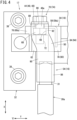
FIG. 4] FIG. 4 is an enlarged plan view of the vicinity of a first intermediate connecting member ofFIG. 2 . - [
FIG. 5] FIG. 5 is an enlarged cross-sectional view of a first intermediate connecting member ofFIG. 3 near a corner portion. - [
FIG. 6] FIG. 6 is an enlarged cross-sectional view showing the vicinity of a first pedestal of a support member according to the modified example. - [
FIG. 7] FIG. 7 is an external perspective view showing a first intermediate connecting member of an intermediate connecting portion. - [
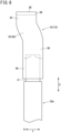
FIG. 8] FIG. 8 is a plan view of the first intermediate connecting member shown inFIG. 7 . - [
FIG. 9] FIG. 9 is a side view of the first intermediate connecting member shown inFIG. 7 . - As shown in
FIG. 1 , abattery pack 10 according to the present embodiment can be applied as a portable battery pack that is mounted in an attachable and detachable manner in an electric vehicle (not shown) such as an electric assist bicycle or an electric motorcycle. Thebattery pack 10 can be applied to various external devices that require power. An example in which thebattery pack 10 is mounted in an electric vehicle will be described below. The up-down direction of thebattery pack 10 is the vertical direction when thebattery pack 10 is mounted in an electric vehicle, or a direction inclined with respect to the vertical direction. - As shown in
FIG. 1 , thebattery pack 10 includes acase 12, abattery core pack 14, and aconnector structure 17. - The
case 12 is formed of a metal material such as aluminum or a resin material, for example. Thecase 12 accommodates thebattery core pack 14 and thesupport member 18. Thecase 12 has abottom case 20, anouter case 22, and atop case 24. The axial direction of thecase 12 shown inFIG. 1 is referred to as the third direction (arrow Z direction). - The
bottom case 20 is placed at a lower part of thecase 12. Thebottom case 20 covers the bottom of thebattery core pack 14. Theouter case 22 is formed in a hollow shape and is attached to an upper end portion of thebottom case 20. Theouter case 22 covers the side surfaces of thebattery core pack 14. Thetop case 24 is attached to an upper end portion of theouter case 22. Thetop case 24 covers an upper portion of thebattery core pack 14. An upper portion of thetop case 24 is provided with ahandle 26. Thehandle 26 is graspable when a user carries thebattery pack 10. - Inside the
case 12, a battery management unit (BMU) 28 is housed. Thebattery management unit 28 controls charging and discharging of thebattery core pack 14 and communicates with external devices such as electric vehicles. Thebattery management unit 28 is connected to battery cells (not shown) of thebattery core pack 14. - The
battery management unit 28 is electrically connected to anintermediate connection portion 16 via a set ofharnesses FIG. 2 . Thebattery management unit 28 is electrically connectable to the electric vehicle via theintermediate connection portion 16 shown inFIG. 2 . The extending direction ofend portions 31 of theharnesses members 54, 56) shown inFIG. 2 is referred to as a first direction (arrow-X direction). - The
battery core pack 14 shown inFIG. 1 is housed and held inside thecase 12. Thebattery core pack 14 is covered by thecase 12. Thebattery core pack 14 holds a plurality of battery cells via a cell holder (not shown). The battery cell is, for example, a lithium secondary battery that can be repeatedly charged and discharged. Thebattery core pack 14 is electrically connected with thebattery management unit 28. Theconnector structure 17 is provided in thebottom case 20. - As shown in
FIGS. 1 and2 , theconnector structure 17 has thesupport member 18. Thesupport member 18 is formed of a resin material. Thesupport member 18 is disposed along a width direction (arrow-Y direction, which will be referred to as a second direction hereinafter) orthogonal to the axial direction of thecase 12. As shown inFIG. 2 , thesupport member 18 has asupport base 32 and a pair of first andsecond pedestals support base 32 is placed along a bottom 20a of thebottom case 20. Thesupport base 32 is secured to the bottom 20a of thebottom case 20 with a plurality of securing bolts 38 (seeFIG. 3 ). At this time, a seal member (not shown) is sandwiched between thesupport base 32 and thebottom case 20. The seal member prevents moisture and the like from entering thecase 12 from the outside of thecase 12. Thesupport member 18 is secured to thecase 12, for example, at a position where the securingbolts 38 avoids the sealing member. - The
connector structure 17 further includes apower connection portion 40 and asignal connection portion 42. Thesupport base 32 supports thepower connection portion 40 and thesignal connection portion 42. Thepower connection portion 40 has a pair of first and second connectingterminals terminals portion 16 described later. - As shown in
FIG. 2 , the first connectingterminal 44 is placed at one end in the width direction of thesupport base 32. The second connectingterminal 46 is arranged at the other end of thesupport base 32 in the width direction. In the second direction (arrow-Y direction) of thesupport base 32, the first connectingterminal 44 and the second connectingterminal 46 are symmetrical. The configuration of the first connectingterminal 44 will be described below, and the detailed description of the configuration of the second connectingterminal 46 will be omitted. - As shown in
FIGS. 3 to 5 , the first connectingterminal 44 has acontact portion 48 and a supportedportion 50. Thecontact portion 48 has acontact surface 48a that makes contact with theintermediate connection portion 16. Thecontact portion 48 is held by afastening portion 58 of thefirst pedestal 34, which will be described later. The supportedportion 50 is bent at a right angle from a width-direction end of thefastening portion 58 by a bending process. The supportedportion 50 is held by a holdingportion 60 of thefirst pedestal 34, which will be described later. The first connectingterminal 44 has an L-shape when viewed from the axial direction of thecase 12 shown inFIG. 3 . - The supported
portion 50 protrudes downward from the support base 32 (seeFIG. 3 ). Alower portion 45 of the first connectingterminal 44 is formed in a plate spring shape and is accommodated in an accommodating space (not shown) formed in a lower portion of thesupport base 32. When thebattery pack 10 is accommodated in a battery pack accommodating portion of the electric vehicle (not shown), the first connectingterminal 44 is electrically connected to a connector provided on the electric vehicle side. The power of thebattery pack 10 can be supplied to a driving motor of the electric vehicle via the first connectingterminal 44. - As shown in
FIG. 2 , thesignal connection portion 42 has a plurality of third connectingterminals 52. The third connectingterminal 52 is made of metal and connected to thebattery management unit 28. The third connectingterminal 52 is placed between the first connectingterminal 44 and the second connectingterminal 46, equidistant from them in the width direction. The third connectingterminal 52 extends in the up-down direction (the arrow-Z direction inFIG. 1 ) of thebattery pack 10 shown inFIG. 1 . When thebattery pack 10 is accommodated in the battery pack accommodating portion of the electric vehicle, the third connectingterminal 52 is electrically connected to the connector provided on the electric vehicle side. Vehicle information and the like are communicated between the electric vehicle and thebattery pack 10 via the third connectingterminal 52. - As shown in
FIG. 2 , the first andsecond pedestals support base 32 toward the outer case 22 (seeFIG. 1 ). Thefirst pedestal 34 is placed at one end in the width direction of thesupport base 32. Thefirst pedestal 34 holds the first connectingterminal 44. The first intermediate connectingmember 54 of the intermediate connectingportion 16 is connected to thefirst pedestal 34. Thesecond pedestal 36 is disposed at the other end in the width direction of thesupport base 32. Thesecond pedestal 36 holds the second connectingterminal 46. The second intermediate connectingmember 56 of the intermediate connectingportion 16 is connected to thesecond pedestal 36. - The
first pedestal 34 and thesecond pedestal 36 are arranged at positions avoiding the seal member (not shown). As shown inFIG. 2 , thefirst pedestal 34 and thesecond pedestal 36 are symmetrical in the second direction (arrow-Y direction) of thesupport base 32. Thefirst pedestal 34 will be described below, and the detailed description of thesecond pedestal 36 will be omitted. - As shown in
FIGS. 3 and4 , thefirst pedestal 34 has afastening portion 58, a holdingportion 60, and aspace portion 62. Thefirst pedestal 34 holds the first connectingterminal 44 and is connected with the first intermediate connectingmember 54 of the intermediate connectingportion 16. - The
fastening portion 58 is disposed at the tip along the first direction (arrow-X direction) at thefirst pedestal 34. Thefastening portion 58 has afastening surface 58a to which the first intermediate connectingmember 54 is fastened. Thefastening portion 58 extends from thesupport base 32 in the third direction (arrow-Z direction). Thefastening surface 58a is placed at the tip along the first direction of thefastening portion 58. Thefastening surface 58a is formed flat along the second direction (arrow-Y direction) and the third direction (arrow-Z direction). As shown inFIG. 3 , thefastening surface 58a has an accommodating portion 64 (seeFIG. 5 ) that is dented from thefastening surface 58a toward theharness 30a. Thecontact portion 48 of the first connectingterminal 44 is accommodated in theaccommodating portion 64. - As shown in
FIG. 5 , thefastening surface 58a of thefastening portion 58 and thecontact surface 48a of the first connectingterminal 44 in the first direction are flush with each other. That is, thecontact surface 48a does not project from thefastening surface 58a in the first direction (arrow-X direction). - As shown in
FIGS. 4 and5 , theterminal connecting portions 88 of the first intermediate connectingmember 54, which will be described later, abut on the fastening surfaces 58a of thefastening portions 58. At this time, the first intermediate connectingmember 54 is in contact with thecontact surface 48a of the first connectingterminal 44 at thefastening portion 58. - Inside the
fastening portion 58, there is provided ahole portion 66 that extends from theaccommodating portion 64 further toward theharness 30a. Thehole portion 66 communicates with thespace portion 62. Anut 68 is held in the hole portion 66 (seeFIG. 5 ). When the first intermediate connectingmember 54 is fastened to thefastening portion 58, a threadedportion 72 of thefastening bolt 70 as the fastening member is screwed into thenut 68. The first intermediate connectingmember 54 is fastened to thefastening surface 58a of thefastening portion 58 by ahead portion 74 of thefastening bolt 70. - As shown in
FIGS. 3 and4 , the holdingportion 60 is provided at an upper portion of thefirst pedestal 34. The holdingportion 60 has a holdingsurface 60a that is formed flat along the second direction (arrow-Y direction) and is parallel to thesupport base 32. The holdingsurface 60a of the holdingportion 60 and thefastening surface 58a of thefastening portion 58 are orthogonal to each other (seeFIG. 5 ). Amain body 84 of the first intermediate connectingmember 54, which will be described later, abuts on and is placed in contact with the holdingsurface 60a. - The holding
portion 60 has afirst holding site 76 and asecond holding site 78. Thefirst holding site 76 is linearly arranged with thefastening portion 58 along the first direction (arrow-X direction). Thefirst holding site 76 is arranged in the direction of theharness 30a along the first direction with respect to thefastening portion 58. Thesecond holding site 78 is placed apart from thefastening portion 58 relative to thefirst holding site 76. Thesecond holding site 78 is disposed inward in the width direction (toward thesecond pedestal 36 inFIG. 2 ) with respect to thefirst holding site 76. As shown inFIG. 4 , thefirst holding site 76 and thesecond holding site 78 are arranged to be shifted in the second direction (arrow-Y direction). - The supported
portion 50 of the first connectingterminal 44 is held inside the first andsecond holding sites portion 50 is held along the first direction at thesecond holding site 78. - As shown in
FIG. 5 , acorner portion 80 is provided at the boundary between thefastening portion 58 and thefirst holding site 76. The outer surface of thecorner portion 80 is formed in a circular arc shape in cross section. Thecorner portion 80 has anotch portion 82 cut inward from the outer surface. Thenotch portion 82 is a concave portion dented radially inward from the outer surface of thecorner portion 80. The sectional shape of thenotch portion 82 is arc-shaped. When the first intermediate connectingmember 54 is connected to thefirst pedestal 34, thenotch portion 82 faces acorner portion 98 of the first intermediate connectingmember 54. Thenotch portion 82 acts as a relief away from thecorner portion 98. - The cross-sectional shape of the
notch portion 82 is not limited to an arc shape and may be anotch portion 82a that is an inclined surface formed by thecorner portion 80 cut inward from the outer surface, as in thefirst pedestal 34a according to a modified example shown inFIG. 6 . Thenotch portion 82a is inclined in a direction away from thecorner portion 98 of the first intermediate connectingmember 54. Thenotch portion 82a is inclined downward from the holdingsurface 60a of the holdingportion 60 toward thefastening surface 58a. - As shown in
FIGS. 3 and4 , thespace portion 62 is a space that is placed in the direction of theharness 30a with respect to thefastening portion 58. Thespace portion 62 is provided between thefirst holding site 76 and thesecond holding site 78. Thespace portion 62 is a hollow portion formed to reduce the weight of thesupport member 18. Thespace portion 62 communicates with thehole portion 66 of thefastening portion 58. The threadedportion 72 of thefastening bolt 70 fastened to thefastening portion 58 is accommodated in thespace portion 62. Thespace portion 62 opens upward in the axial direction (third direction) of thecase 12. - As shown in
FIG. 2 , theintermediate connection portion 16 electrically connects thepower connection portion 40 and theend portion 31 of theharness battery management unit 28. The intermediate connectingportion 16 has a pair of first and second intermediate connectingmembers members - The first and second intermediate connecting
members end portion 31 of theharness support member 18. - As shown in
FIG. 2 , the first intermediate connectingmember 54 is held by thefirst pedestal 34 of thesupport member 18. The first intermediate connectingmember 54 electrically connects theend portion 31 of oneharness 30a and the first connectingterminal 44 with each other. The second intermediate connectingmember 56 is held by thesecond pedestal 36 of thesupport member 18. The second intermediate connectingmember 56 electrically connects theend portion 31 of theother harness 30b and the second connectingterminal 46 with each other. In the second direction (arrow-Y direction) of thesupport member 18, the first intermediate connectingmember 54 and the second intermediate connectingmember 56 are symmetrical. Since the first intermediate connectingmember 54 and the second intermediate connectingmember 56 are symmetrical, it is possible to prevent the misassembling thesupport member 18 with respect to thefirst pedestal 34 and thesecond pedestal 36. The first intermediate connectingmember 54 will be described below, and the detailed description of the second intermediate connectingmember 56 will be omitted. - As shown in
FIGS. 7 to 9 , the first intermediate connectingmember 54 has abody portion 84, aharness connecting portion 86, and aterminal connecting portion 88. - The
main body 84 extends in a first direction (arrow-X direction), which is the extending direction of theend portion 31 of theharness 30a. Themain body 84 has a flat shape along the width direction (second direction). Themain body 84 has a constant plate thickness in the third direction (arrow-Z direction). As shown inFIG. 4 , part of themain body 84 is held on the holdingsurface 60a, facing the holdingportion 60 of thefirst pedestal 34. Themain body 84 is formed with a constant width in the second direction. - As shown in
FIGS. 4 ,7 and8 , themain body 84 has a first extendingend portion 90 at one end in the extending direction along the first direction. The first extendingend portion 90 extends in the first direction and is connected to theharness connecting portion 86. The first extendingend portion 90 is held in contact with the holdingsurface 60a of thefirst holding site 76 of the first pedestal 34 (seeFIG. 3 ). - The other end of the
main body 84 in the extending direction along the first direction is provided with a second extendingend portion 92. The second extendingend portion 92 extends along the first direction and is connected to theterminal connecting portion 88. - The
terminal connecting portion 88 and the second extendingend portion 92 are arranged to be shifted in the second direction (arrow-Y direction) of thesupport base 32 with respect to theharness connecting portion 86 and the first extendingend portion 90. The shifted direction of theterminal connecting portion 88 and the second extendingend portion 92 is a direction away from the second intermediate connecting member 56 (arrow-Y1 direction inFIG. 2 ). - As shown in
FIG. 4 , themain body 84 includes a shiftingportion 94 between the first extendingend portion 90 and the second extendingend portion 92. The shiftingportion 94 connects the firstextended end portion 90 and the secondextended end portion 92 shifted in the second direction (arrow-Y direction) and is formed in an oblique shape inclined with respect to the first direction. - When the first intermediate connecting
member 54 is attached to thefirst pedestal 34, the second extendingend portion 92 and a large portion of the shiftingportion 94 face thespace portion 62. When viewed from the axial direction of thecase 12 shown inFIG. 4 , part of widthwise inner sides of the second extendingend portion 92 and the shiftingportion 94, which face the direction toward the second intermediate connectingmember 56, are held in contact with the holdingsurface 60a of thesecond holding site 78. - That is, the first extending
end portion 90 of themain body 84 is placed in thefirst holding site 76 of the holdingportion 60, and part of the shiftingportion 94 and the second extendingend portion 92 are placed in thesecond holding site 78 of the holding portion 60 (seeFIG. 4 ). Thus, themain body 84 of the first intermediate connectingmember 54 is held along the holdingsurface 60a of the holdingportion 60. - The
harness connecting portion 86 is formed in a cylindrical shape and extends along the first direction. When viewed from the axial direction of thecase 12 shown inFIG. 4 , theharness connecting portion 86 is arranged in parallel with the first direction (arrow-X direction), which is the extending direction of theend portions 31 of theharnesses harness connecting portion 86 and theend portion 31 of theharness 30a are arranged linearly. The take-out position and the take-out direction of theend portion 31 of theharness 30a are determined by thebattery management unit 28 to which theharness 30a (30b) is connected. - The
end portion 31 of theharness 30a is inserted into theharness connection portion 86, and theharness connection portion 86 and theend portion 31 of theharness 30a are electrically connected. Theharness connecting portion 86 and theend portion 31 of theharness 30a are linearly connected along the first direction (arrow-X direction). - As shown in
FIGS. 3 and5 , theterminal connecting portion 88 is bent in the third direction (arrow-Z direction) with respect to themain body 84. That is, theterminal connecting portion 88 is bent in the plate thickness direction of thebody portion 84. Theterminal connecting portion 88 is formed perpendicularly downward from the second extendingend portion 92 of themain body 84. Theterminal connecting portion 88 is shifted in the second direction (arrow-Y1 direction) away from the second intermediate connectingmember 56 with respect to theharness connecting portion 86. Theterminal connecting portion 88 is arranged in parallel with thecontact surface 48a of the first connectingterminal 44. Theterminal connecting portion 88 and thecontact surface 48a of the first connectingterminal 44 are in contact with each other and electrically connected. - As shown in
FIGS. 3 and5 , theterminal connecting portion 88 has abolt hole 96 in the center. Thefastening bolt 70 is inserted into thebolt hole 96. Thefastening bolt 70 is inserted into thebolt hole 96 and then theterminal connecting portion 88 is secured to thefastening portion 58 of thefirst pedestal 34 by thefastening bolt 70 from the first direction. At this time, themain body 84 is placed in contact with the holdingsurface 60a of the holding portion 60 (first andsecond holding sites 76, 78). - The
curved corner portion 98 is provided between theterminal connecting portion 88 and themain body 84. When viewed from the second direction shown inFIG. 5 , the cross-sectional shape of thecorner portion 98 is an arc shape. When the first intermediate connectingmember 54 is attached to thefirst pedestal 34, thecorner portion 98 faces thecorner portion 80. The inner surface of thecorner portion 98 has athin portion 100, which is dented in the plate thickness direction. - The
thin portion 100 is formed through, for example, a striking process when the first intermediate connectingmember 54 is press-formed. Thethin portion 100 makes the thickness of thecorner portion 98 thinner than the plate thicknesses of theterminal connecting portion 88 and themain body 84. Thethin portion 100 may be formed by, for example, machining the inner surface of thecorner portion 98. - When the first intermediate connecting
member 54 is attached to thefirst pedestal 34, thethin portion 100 and thenotch portion 82 prevent thecorner portion 98 and thecorner portion 80 from coming into contact with each other even if the inner surface of thecorner portion 98 bulges inward due to a bending process (seeFIG. 5 ). - As described above, in the embodiment of the present invention, by providing the shifting
portions 94 on the first and second intermediate connectingmembers end portions 31 of theharnesses members terminals end portions 31 of theharnesses second pedestals main body 84 does not need to be flattened and notched in the second direction at the first and second intermediate connectingmembers battery core pack 14 to the first and second connectingterminals harnesses members - This makes it possible to achieve both the connection of the first and second intermediate connecting
members terminals members - When a force is applied from the
harnesses harness connecting portion 86 in the rotational direction and a rotational moment is generated in the first and second intermediate connectingmembers terminals members - When viewed from the axial direction (third direction) of the
case 12, part of the shiftingportion 94 of the first and second intermediate connectingmembers space portion 62 and is held by thesecond holding site 78 of the holdingportion 60. Thus, by placing the shiftingportion 94 on thesecond holding site 78 of the holdingportion 60, it is possible to hold themain body 84, which faces thespace portion 62, on the first andsecond pedestals second holding site 78 in addition to thefirst holding site 76 stably in the third direction. - When the first and second intermediate connecting
members harness connecting portion 86 is formed in parallel with the first direction, which is the extending direction of theend portions 31 of theharnesses end portions 31 of theharnesses harness connection portions 86, theend portions 31 of theharnesses harness connection portions 86 smoothly without any difficulty. - In respect of the first and second intermediate connecting
members thin portions 100 make the plate thickness of thecorner portion 98 thinner than the plate thicknesses of theterminal connecting portion 88 and themain body 84, whereby theterminal connecting portion 88 can be formed by easily bending the end portion of themain body 84. - In respect of the first and second intermediate connecting
members terminal connecting portion 88 by bending theterminal connecting portion 88 in the plate thickness direction (the third direction, the arrow-Z direction) of themain body 84 with respect to themain body 84. - The
corner portion 80 of the first andsecond pedestals corner portion 98 of the first and second intermediate connectingmembers notch portion 82 cut in a direction away from thecorner portion 98. Thus, when theterminal connecting portions 88 of the first and second intermediate connectingmembers second pedestals support member 18, respectively, the inner surface of thecorner portion 98 is prevented from contacting the outer surface of thecorner portion 80 by thenotch portion 82 even if the inner surface of thecorner portion 98 bulged inward at the bending process of theterminal connecting portion 88. - Thus, the
terminal connecting portions 88 are not lifted from thefastening portions 58 of the first andsecond pedestals corner portions 98, and theterminal connecting portion 88 can be securely fastened to the fastening surfaces 58a of thefastening portions 58. - In a first direction, which is the extending direction of the
end portions 31 of theharness second pedestals terminals fastening portions 58 are arranged to be flush with each other. Thus, by making theterminal connecting portions 88 of the first and second intermediate connectingmembers fastening surfaces 58a, it is possible to make theterminal connecting portions 88 abut on the contact surfaces 48a of the first and second connectingterminals terminal connecting portions 88 and the first and second connectingterminals - The above embodiments are summarized as follows.
- The above embodiment is a battery pack (10) comprising a battery core pack (14) that includes a plurality of battery cells;
- a case (12) that accommodates the battery core pack;
- a connecting terminal (44, 46) that is arranged at one end of the case and is configured to be connected to an external device;
- a support member (18) that is held by the case and supports the connecting terminal;
- an intermediate connecting member (54, 56) that is held by the support member and electrically connects the connecting terminal and a harness (30a, 30b) electrically connected to the battery core pack,
- wherein the intermediate connecting member is formed of a metal plate and includes a main body (84) that extends in a first direction, which is an extending direction of an end portion (31) of the harness;
- a harness connecting portion (86) that is formed at one end in an extending direction of the main body and to which the end portion of the harness is connected;
- a terminal connecting portion (88) that is formed at another end in the extending direction of the main body, is arranged to be shifted with respect to the end portion in a second direction orthogonal to the first direction, and is connected to the connecting terminal,
- the main body has a flat shape along the second direction, and includes a first extending end portion (90) that extends along the first direction from the harness connecting portion toward the terminal connecting portion,
- a second extending end portion (92) that extends in the first direction from the terminal connecting portion toward the harness connecting portion and is arranged to be shifted in the second direction with respect to the first extending end portion, and
- a shifting portion (94) that connects the first extending end portion and the second extending end portion with each other.
- The terminal connecting portion is secured in the first direction with respect to a pedestal (34, 36) of the support member with a fastening member (70),
- the pedestal includes a fastening portion (58) including a fastening surface (58a) on which the terminal connecting portion abuts and is fastened in the first direction,
- a holding portion (60) that is orthogonal to the fastening surface of the fastening portion, extends along the first direction, and faces the main body, and
- a space portion (62) that is disposed in a direction of the harness connecting portion with respect to the fastening portion and opens in a third direction orthogonal to the second direction and along the axial direction of the case,
- when viewed from the third direction, part of the shifting portion is shifted in the second direction with respect to the space portion and is placed on the holding portion.
- The harness connecting portion is formed parallel to the first direction when the intermediate connecting member is viewed from the third direction.
- The terminal connecting portion is formed to be bent in the third direction with respect to the main body,
- between the terminal connecting portion and the main body, a corner portion (98) curving when viewed from the second direction is formed, and
- a plate thickness of the corner portion is thinner than plate thicknesses of the terminal connecting portion and the main body.
- The main body has the plate thickness in the third direction, and
the terminal connecting portion is bent in the third direction with respect to the main body. - The pedestal of the support member includes an outer surface (80) facing the corner portion, and the outer surface includes a notch portion (82, 82a) cut in a direction away from the corner portion.
- In the first direction, the fastening surface of the fastening portion where the terminal connecting portion is fastened and a contact surface (48a) of the connecting terminal arranged at the fastening portion are arranged to be flush with each other.
- Note that the present invention is not limited to the above disclosure, and various modifications are possible without departing from the essence and gist of the present invention.
Claims (7)
- A battery pack (10) comprising:a battery core pack (14) that includes a plurality of battery cells;a case (12) that accommodates the battery core pack;a connecting terminal (44, 46) that is arranged at one end of the case and is configured to be connected to an external device;a support member (18) that is held by the case and supports the connecting terminal; andan intermediate connecting member (54, 56) that is held by the support member and electrically connects the connecting terminal and a harness (30a, 30b) electrically connected to the battery core pack,whereinthe intermediate connecting member is formed of a metal plate and includesa main body (84) that extends in a first direction, which is an extending direction of an end portion (31) of the harness,a harness connecting portion (86) that is formed at one end in an extending direction of the main body and to which the end portion of the harness is connected, anda terminal connecting portion (88) that is formed at another end in the extending direction of the main body, is arranged to be shifted with respect to the end portion in a second direction orthogonal to the first direction, and is connected to the connecting terminal,the main body has a flat shape along the second direction and includesa first extending end portion (90) that extends along the first direction from the harness connecting portion toward the terminal connecting portion,a second extending end portion (92) that extends in the first direction from the terminal connecting portion toward the harness connecting portion and is arranged to be shifted in the second direction with respect to the first extending end portion, anda shifting portion (94) that connects the first extending end portion and the second extending end portion with each other.
- The battery pack according to claim 1, whereinthe terminal connecting portion is secured in the first direction with respect to a pedestal (34, 36) of the support member with a fastening member (70),the pedestal includesa fastening portion (58) including a fastening surface (58a) on which the terminal connecting portion abuts and is fastened in the first direction,a holding portion (60) that is orthogonal to the fastening surface of the fastening portion, extends along the first direction, and faces the main body, anda space portion (62) that is disposed in a direction of the harness connecting portion with respect to the fastening portion and opens in a third direction orthogonal to the second direction and along an axial direction of the case, andwhen viewed from the third direction, part of the shifting portion is arranged to be shifted in the second direction with respect to the space portion and is placed on the holding portion.
- The battery pack according to claim 2, wherein
the harness connecting portion is formed parallel to the first direction when the intermediate connecting member is viewed from the third direction. - The battery pack according to claim 2 or 3, whereinthe terminal connecting portion is formed to be bent in the third direction with respect to the main body,between the terminal connecting portion and the main body, a corner portion (98) curving when viewed from the second direction is formed, anda plate thickness of the corner portion is thinner than plate thicknesses of the terminal connecting portion and the main body.
- The battery pack according to claim 4, whereinthe main body has the plate thickness in the third direction, andthe terminal connecting portion is bent in the third direction with respect to the main body.
- The battery pack according to claim 5, wherein
the pedestal of the support member includes an outer surface (80) facing the corner portion, and the outer surface includes a notch portion (82, 82a) cut in a direction away from the corner portion. - The battery pack according to claim 6, wherein
in the first direction, a fastening surface of a fastening portion where the terminal connecting portion is fastened and a contact surface (48a) of the connecting terminal arranged at the fastening portion are arranged to be flush with each other.
Applications Claiming Priority (2)
| Application Number | Priority Date | Filing Date | Title |
|---|---|---|---|
| JP2022059930 | 2022-03-31 | ||
| PCT/JP2023/012487 WO2023190503A1 (en) | 2022-03-31 | 2023-03-28 | Battery pack |
Publications (2)
| Publication Number | Publication Date |
|---|---|
| EP4503291A1 true EP4503291A1 (en) | 2025-02-05 |
| EP4503291A4 EP4503291A4 (en) | 2025-06-04 |
Family
ID=88202546
Family Applications (1)
| Application Number | Title | Priority Date | Filing Date |
|---|---|---|---|
| EP23780512.2A Pending EP4503291A4 (en) | 2022-03-31 | 2023-03-28 | Battery pack |
Country Status (3)
| Country | Link |
|---|---|
| EP (1) | EP4503291A4 (en) |
| JP (1) | JP7738171B2 (en) |
| WO (1) | WO2023190503A1 (en) |
Family Cites Families (5)
| Publication number | Priority date | Publication date | Assignee | Title |
|---|---|---|---|---|
| JP4878473B2 (en) * | 2005-11-22 | 2012-02-15 | 矢崎総業株式会社 | Terminal fitting and electric junction box provided with the terminal fitting |
| JP5939206B2 (en) * | 2013-06-18 | 2016-06-22 | 住友電装株式会社 | Terminal with cover |
| JP2015069953A (en) * | 2013-10-01 | 2015-04-13 | 株式会社オートネットワーク技術研究所 | Electrical connection structure and wiring module using the same |
| JP2017091676A (en) * | 2015-11-05 | 2017-05-25 | 株式会社オートネットワーク技術研究所 | Wiring module |
| JP7595010B2 (en) | 2019-07-16 | 2024-12-05 | 本田技研工業株式会社 | Male connector, female connector, connector structure, manufacturing method for male connector, manufacturing method for female connector |
-
2023
- 2023-03-28 JP JP2024512558A patent/JP7738171B2/en active Active
- 2023-03-28 EP EP23780512.2A patent/EP4503291A4/en active Pending
- 2023-03-28 WO PCT/JP2023/012487 patent/WO2023190503A1/en not_active Ceased
Also Published As
| Publication number | Publication date |
|---|---|
| EP4503291A4 (en) | 2025-06-04 |
| JP7738171B2 (en) | 2025-09-11 |
| JPWO2023190503A1 (en) | 2023-10-05 |
| WO2023190503A1 (en) | 2023-10-05 |
Similar Documents
| Publication | Publication Date | Title |
|---|---|---|
| JP4473485B2 (en) | Battery module | |
| EP4071904B1 (en) | Hybrid circuit board and battery pack having same | |
| US8114540B2 (en) | Buss bar for batteries | |
| JPWO2001017044A1 (en) | Battery module | |
| EP2660898A1 (en) | Power storage device | |
| EP4037081A1 (en) | Battery compartment, battery compartment assembly and electric scooter | |
| JP5326771B2 (en) | Battery pack | |
| JP7417726B2 (en) | Battery modules, battery packs containing them, and automobiles | |
| KR20220012037A (en) | Battery module having a simple connection structure between cell lead and voltage sensing member and battery pack including the same | |
| EP4503291A1 (en) | Battery pack | |
| CN213026344U (en) | Trays, battery packs and electric vehicles | |
| EP3896794B1 (en) | Connector | |
| JP6977484B2 (en) | Power storage device | |
| JP7447428B2 (en) | Power storage device | |
| JP5938778B2 (en) | Battery terminal with current sensor | |
| CN215496892U (en) | Battery module bracket and battery module structure | |
| JPWO2019187316A1 (en) | Electric vehicle with power supply and power supply | |
| JP2006286575A (en) | Secondary battery holding structure | |
| CN211202121U (en) | ECU support and car | |
| JP2018125252A (en) | Power storage device and conductive member | |
| JP4683855B2 (en) | Pack battery | |
| CN115715433A (en) | Battery pack, electronic device, vehicle, and battery management system module | |
| CN223757582U (en) | Cover assembly, cells, batteries and vehicles | |
| CN223378401U (en) | Pole assembly, battery top cover and battery | |
| CN220138608U (en) | battery pack |
Legal Events
| Date | Code | Title | Description |
|---|---|---|---|
| STAA | Information on the status of an ep patent application or granted ep patent |
Free format text: STATUS: THE INTERNATIONAL PUBLICATION HAS BEEN MADE |
|
| PUAI | Public reference made under article 153(3) epc to a published international application that has entered the european phase |
Free format text: ORIGINAL CODE: 0009012 |
|
| STAA | Information on the status of an ep patent application or granted ep patent |
Free format text: STATUS: REQUEST FOR EXAMINATION WAS MADE |
|
| 17P | Request for examination filed |
Effective date: 20241031 |
|
| AK | Designated contracting states |
Kind code of ref document: A1 Designated state(s): AL AT BE BG CH CY CZ DE DK EE ES FI FR GB GR HR HU IE IS IT LI LT LU LV MC ME MK MT NL NO PL PT RO RS SE SI SK SM TR |
|
| A4 | Supplementary search report drawn up and despatched |
Effective date: 20250508 |
|
| RIC1 | Information provided on ipc code assigned before grant |
Ipc: H01R 11/12 20060101ALI20250430BHEP Ipc: H01R 11/11 20060101ALI20250430BHEP Ipc: H01M 50/298 20210101ALI20250430BHEP Ipc: H01M 50/296 20210101AFI20250430BHEP |
|
| DAV | Request for validation of the european patent (deleted) | ||
| DAX | Request for extension of the european patent (deleted) | ||
| RAP3 | Party data changed (applicant data changed or rights of an application transferred) |
Owner name: HONDA MOTOR CO., LTD. |
|
| GRAP | Despatch of communication of intention to grant a patent |
Free format text: ORIGINAL CODE: EPIDOSNIGR1 |
|
| STAA | Information on the status of an ep patent application or granted ep patent |
Free format text: STATUS: GRANT OF PATENT IS INTENDED |
|
| INTG | Intention to grant announced |
Effective date: 20251217 |
|
| GRAS | Grant fee paid |
Free format text: ORIGINAL CODE: EPIDOSNIGR3 |
|
| GRAA | (expected) grant |
Free format text: ORIGINAL CODE: 0009210 |
|
| STAA | Information on the status of an ep patent application or granted ep patent |
Free format text: STATUS: THE PATENT HAS BEEN GRANTED |