EP4503284A2 - Energy storage system - Google Patents
Energy storage system Download PDFInfo
- Publication number
- EP4503284A2 EP4503284A2 EP24170857.7A EP24170857A EP4503284A2 EP 4503284 A2 EP4503284 A2 EP 4503284A2 EP 24170857 A EP24170857 A EP 24170857A EP 4503284 A2 EP4503284 A2 EP 4503284A2
- Authority
- EP
- European Patent Office
- Prior art keywords
- disposed
- energy storage
- cabinet
- door member
- storage system
- Prior art date
- Legal status (The legal status is an assumption and is not a legal conclusion. Google has not performed a legal analysis and makes no representation as to the accuracy of the status listed.)
- Pending
Links
Images



Classifications
-
- H—ELECTRICITY
- H01—ELECTRIC ELEMENTS
- H01M—PROCESSES OR MEANS, e.g. BATTERIES, FOR THE DIRECT CONVERSION OF CHEMICAL ENERGY INTO ELECTRICAL ENERGY
- H01M50/00—Constructional details or processes of manufacture of the non-active parts of electrochemical cells other than fuel cells, e.g. hybrid cells
- H01M50/20—Mountings; Secondary casings or frames; Racks, modules or packs; Suspension devices; Shock absorbers; Transport or carrying devices; Holders
- H01M50/204—Racks, modules or packs for multiple batteries or multiple cells
- H01M50/207—Racks, modules or packs for multiple batteries or multiple cells characterised by their shape
- H01M50/209—Racks, modules or packs for multiple batteries or multiple cells characterised by their shape adapted for prismatic or rectangular cells
-
- A—HUMAN NECESSITIES
- A62—LIFE-SAVING; FIRE-FIGHTING
- A62C—FIRE-FIGHTING
- A62C3/00—Fire prevention, containment or extinguishing specially adapted for particular objects or places
- A62C3/16—Fire prevention, containment or extinguishing specially adapted for particular objects or places in electrical installations, e.g. cableways
-
- A—HUMAN NECESSITIES
- A62—LIFE-SAVING; FIRE-FIGHTING
- A62D—CHEMICAL MEANS FOR EXTINGUISHING FIRES OR FOR COMBATING OR PROTECTING AGAINST HARMFUL CHEMICAL AGENTS; CHEMICAL MATERIALS FOR USE IN BREATHING APPARATUS
- A62D1/00—Fire-extinguishing compositions; Use of chemical substances in extinguishing fires
- A62D1/0064—Gels; Film-forming compositions
-
- H—ELECTRICITY
- H01—ELECTRIC ELEMENTS
- H01M—PROCESSES OR MEANS, e.g. BATTERIES, FOR THE DIRECT CONVERSION OF CHEMICAL ENERGY INTO ELECTRICAL ENERGY
- H01M10/00—Secondary cells; Manufacture thereof
- H01M10/42—Methods or arrangements for servicing or maintenance of secondary cells or secondary half-cells
- H01M10/4207—Methods or arrangements for servicing or maintenance of secondary cells or secondary half-cells for several batteries or cells simultaneously or sequentially
-
- H—ELECTRICITY
- H01—ELECTRIC ELEMENTS
- H01M—PROCESSES OR MEANS, e.g. BATTERIES, FOR THE DIRECT CONVERSION OF CHEMICAL ENERGY INTO ELECTRICAL ENERGY
- H01M10/00—Secondary cells; Manufacture thereof
- H01M10/60—Heating or cooling; Temperature control
- H01M10/61—Types of temperature control
- H01M10/613—Cooling or keeping cold
-
- H—ELECTRICITY
- H01—ELECTRIC ELEMENTS
- H01M—PROCESSES OR MEANS, e.g. BATTERIES, FOR THE DIRECT CONVERSION OF CHEMICAL ENERGY INTO ELECTRICAL ENERGY
- H01M10/00—Secondary cells; Manufacture thereof
- H01M10/60—Heating or cooling; Temperature control
- H01M10/62—Heating or cooling; Temperature control specially adapted for specific applications
- H01M10/627—Stationary installations, e.g. power plant buffering or backup power supplies
-
- H—ELECTRICITY
- H01—ELECTRIC ELEMENTS
- H01M—PROCESSES OR MEANS, e.g. BATTERIES, FOR THE DIRECT CONVERSION OF CHEMICAL ENERGY INTO ELECTRICAL ENERGY
- H01M10/00—Secondary cells; Manufacture thereof
- H01M10/60—Heating or cooling; Temperature control
- H01M10/65—Means for temperature control structurally associated with the cells
- H01M10/655—Solid structures for heat exchange or heat conduction
- H01M10/6556—Solid parts with flow channel passages or pipes for heat exchange
-
- H—ELECTRICITY
- H01—ELECTRIC ELEMENTS
- H01M—PROCESSES OR MEANS, e.g. BATTERIES, FOR THE DIRECT CONVERSION OF CHEMICAL ENERGY INTO ELECTRICAL ENERGY
- H01M10/00—Secondary cells; Manufacture thereof
- H01M10/60—Heating or cooling; Temperature control
- H01M10/65—Means for temperature control structurally associated with the cells
- H01M10/656—Means for temperature control structurally associated with the cells characterised by the type of heat-exchange fluid
- H01M10/6561—Gases
-
- H—ELECTRICITY
- H01—ELECTRIC ELEMENTS
- H01M—PROCESSES OR MEANS, e.g. BATTERIES, FOR THE DIRECT CONVERSION OF CHEMICAL ENERGY INTO ELECTRICAL ENERGY
- H01M10/00—Secondary cells; Manufacture thereof
- H01M10/60—Heating or cooling; Temperature control
- H01M10/65—Means for temperature control structurally associated with the cells
- H01M10/656—Means for temperature control structurally associated with the cells characterised by the type of heat-exchange fluid
- H01M10/6567—Liquids
-
- H—ELECTRICITY
- H01—ELECTRIC ELEMENTS
- H01M—PROCESSES OR MEANS, e.g. BATTERIES, FOR THE DIRECT CONVERSION OF CHEMICAL ENERGY INTO ELECTRICAL ENERGY
- H01M50/00—Constructional details or processes of manufacture of the non-active parts of electrochemical cells other than fuel cells, e.g. hybrid cells
- H01M50/20—Mountings; Secondary casings or frames; Racks, modules or packs; Suspension devices; Shock absorbers; Transport or carrying devices; Holders
- H01M50/233—Mountings; Secondary casings or frames; Racks, modules or packs; Suspension devices; Shock absorbers; Transport or carrying devices; Holders characterised by physical properties of casings or racks, e.g. dimensions
- H01M50/24—Mountings; Secondary casings or frames; Racks, modules or packs; Suspension devices; Shock absorbers; Transport or carrying devices; Holders characterised by physical properties of casings or racks, e.g. dimensions adapted for protecting batteries from their environment, e.g. from corrosion
-
- H—ELECTRICITY
- H01—ELECTRIC ELEMENTS
- H01M—PROCESSES OR MEANS, e.g. BATTERIES, FOR THE DIRECT CONVERSION OF CHEMICAL ENERGY INTO ELECTRICAL ENERGY
- H01M50/00—Constructional details or processes of manufacture of the non-active parts of electrochemical cells other than fuel cells, e.g. hybrid cells
- H01M50/20—Mountings; Secondary casings or frames; Racks, modules or packs; Suspension devices; Shock absorbers; Transport or carrying devices; Holders
- H01M50/244—Secondary casings; Racks; Suspension devices; Carrying devices; Holders characterised by their mounting method
-
- H—ELECTRICITY
- H01—ELECTRIC ELEMENTS
- H01M—PROCESSES OR MEANS, e.g. BATTERIES, FOR THE DIRECT CONVERSION OF CHEMICAL ENERGY INTO ELECTRICAL ENERGY
- H01M50/00—Constructional details or processes of manufacture of the non-active parts of electrochemical cells other than fuel cells, e.g. hybrid cells
- H01M50/20—Mountings; Secondary casings or frames; Racks, modules or packs; Suspension devices; Shock absorbers; Transport or carrying devices; Holders
- H01M50/258—Modular batteries; Casings provided with means for assembling
-
- H—ELECTRICITY
- H01—ELECTRIC ELEMENTS
- H01M—PROCESSES OR MEANS, e.g. BATTERIES, FOR THE DIRECT CONVERSION OF CHEMICAL ENERGY INTO ELECTRICAL ENERGY
- H01M50/00—Constructional details or processes of manufacture of the non-active parts of electrochemical cells other than fuel cells, e.g. hybrid cells
- H01M50/20—Mountings; Secondary casings or frames; Racks, modules or packs; Suspension devices; Shock absorbers; Transport or carrying devices; Holders
- H01M50/289—Mountings; Secondary casings or frames; Racks, modules or packs; Suspension devices; Shock absorbers; Transport or carrying devices; Holders characterised by spacing elements or positioning means within frames, racks or packs
-
- H—ELECTRICITY
- H01—ELECTRIC ELEMENTS
- H01M—PROCESSES OR MEANS, e.g. BATTERIES, FOR THE DIRECT CONVERSION OF CHEMICAL ENERGY INTO ELECTRICAL ENERGY
- H01M50/00—Constructional details or processes of manufacture of the non-active parts of electrochemical cells other than fuel cells, e.g. hybrid cells
- H01M50/30—Arrangements for facilitating escape of gases
- H01M50/35—Gas exhaust passages comprising elongated, tortuous or labyrinth-shaped exhaust passages
- H01M50/367—Internal gas exhaust passages forming part of the battery cover or case; Double cover vent systems
-
- H—ELECTRICITY
- H01—ELECTRIC ELEMENTS
- H01M—PROCESSES OR MEANS, e.g. BATTERIES, FOR THE DIRECT CONVERSION OF CHEMICAL ENERGY INTO ELECTRICAL ENERGY
- H01M50/00—Constructional details or processes of manufacture of the non-active parts of electrochemical cells other than fuel cells, e.g. hybrid cells
- H01M50/30—Arrangements for facilitating escape of gases
- H01M50/383—Flame arresting or ignition-preventing means
-
- H—ELECTRICITY
- H01—ELECTRIC ELEMENTS
- H01M—PROCESSES OR MEANS, e.g. BATTERIES, FOR THE DIRECT CONVERSION OF CHEMICAL ENERGY INTO ELECTRICAL ENERGY
- H01M2220/00—Batteries for particular applications
- H01M2220/10—Batteries in stationary systems, e.g. emergency power source in plant
-
- H—ELECTRICITY
- H01—ELECTRIC ELEMENTS
- H01M—PROCESSES OR MEANS, e.g. BATTERIES, FOR THE DIRECT CONVERSION OF CHEMICAL ENERGY INTO ELECTRICAL ENERGY
- H01M50/00—Constructional details or processes of manufacture of the non-active parts of electrochemical cells other than fuel cells, e.g. hybrid cells
- H01M50/20—Mountings; Secondary casings or frames; Racks, modules or packs; Suspension devices; Shock absorbers; Transport or carrying devices; Holders
- H01M50/251—Mountings; Secondary casings or frames; Racks, modules or packs; Suspension devices; Shock absorbers; Transport or carrying devices; Holders specially adapted for stationary devices, e.g. power plant buffering or backup power supplies
-
- Y—GENERAL TAGGING OF NEW TECHNOLOGICAL DEVELOPMENTS; GENERAL TAGGING OF CROSS-SECTIONAL TECHNOLOGIES SPANNING OVER SEVERAL SECTIONS OF THE IPC; TECHNICAL SUBJECTS COVERED BY FORMER USPC CROSS-REFERENCE ART COLLECTIONS [XRACs] AND DIGESTS
- Y02—TECHNOLOGIES OR APPLICATIONS FOR MITIGATION OR ADAPTATION AGAINST CLIMATE CHANGE
- Y02E—REDUCTION OF GREENHOUSE GAS [GHG] EMISSIONS, RELATED TO ENERGY GENERATION, TRANSMISSION OR DISTRIBUTION
- Y02E60/00—Enabling technologies; Technologies with a potential or indirect contribution to GHG emissions mitigation
- Y02E60/10—Energy storage using batteries
Definitions
- Embodiments of the present disclosure relate to an energy storage system.
- An energy storage system may be a device or system which may increase overall power usage efficiency by storing power that has already been produced and then supplying the stored power when the power is necessary.
- a fire may occur in a process of using the energy storage system.
- there is a risk of explosion as an internal pressure of the energy storage system is increased due to a gas caused by the fire. Accordingly, there is a need for a structure enabling safe emission of the gas even when the gas occurs in the energy storage system.
- An aspect of the present disclosure may provide an energy storage system modularized and manufactured to be transported in a complete manufacturing state, thus enabling rapid implementation of a large-capacity of an energy source at an installation destination.
- Another aspect of the present disclosure may provide an energy storage system having a structure enabling safe emission of gas occurring in the system.
- an energy storage system may include: a cabinet including a mounting portion capable of mounting a plurality of battery modules thereon and a door member capable of being opened and closed; and a venting portion emitting gas occurring in an internal space of the cabinet, wherein the venting portion includes at least one inlet communicating with the internal space and allowing the gas to flow into the inlet; and at least one outlet disposed in an outer surface of the cabinet and communicating with the inlet.
- the cabinet may further include a top frame disposed above the mounting portion and a bottom frame disposed below the mounting portion, and the outlet may be open in the top frame toward the bottom frame.
- the door member may face the mounting portion in a first direction
- the top frame may include a first surface facing the door member in a second direction, perpendicular to the first direction, and the outlet may be disposed in the first surface
- a separation space may be formed between the first surface and the door member, and the outlet may communicate with the separation space.
- the top frame may include a hollow portion communicating with each of the inlet and the outlet.
- the top frame may further include a second surface exposed to the internal space, and the inlet may be disposed in the second surface.
- the at least one inlet or the at least one outlet may be disposed in a third direction, perpendicular to both the first direction and the second direction.
- the door member may further include a cooling device capable of supplying a cooling medium to the internal space, and at least one of the inlet or the outlet may be disposed in the door member.
- the cooling device may include a drain pipe allowing condensate occurring in the cooling device to flow, and the inlet and the outlet may communicate with the drain pipe.
- the inlet may be disposed in one end of the drain pipe, and the outlet may be disposed in the other end of the drain pipe.
- the system may further include: a fire extinguishing portion extinguishing a flame occurring in the internal space of the cabinet; and a guide portion dividing a front space formed between the plurality of battery modules and the door member into a plurality of regions.
- the system may further include an electronic component disposed on the inside of the door member, wherein the fire extinguishing portion and the electronic component are disposed together in one of the plurality of regions divided by the guide portion.
- the fire extinguishing portion may include a fire extinguishing agent maintaining a solid state at a temperature of a preset temperature or less and having an aerosol form at a temperature of the preset temperature or more.
- the cabinet may further include a partition dividing the internal space, and the plurality of battery modules may be disposed on both sides of the partition in a height direction of the cabinet.
- the system may further include a plurality of lifting holes disposed in the cabinet and allowing a transport device to be inserted into the holes.
- ordinal numbers such as “first”, “second”, etc. may be used to distinguish components. These ordinal numbers are used to distinguish identical or similar components from each other, and the meaning of the term should not be interpreted limitedly due to the use of these ordinal numbers. For example, a component combined with the ordinal number should not be interpreted as limiting the order of use or arrangement by the number. If necessary, the ordinal numbers may be used interchangeably.
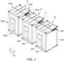
- FIG. 1 is an exemplarily view showing a plurality of energy storage systems 10 connected to each other.
- the energy storage system 10 may be an energy source and used for home or industrial purpose.
- the plurality of energy storage systems 10 may be electrically connected to each other as shown in FIG. 1 .
- Any one of the energy storage system 10 may include a cabinet CB where a battery module (100 in FIGS. 2 and 3 for example) is stored.
- the cabinet CB may include a housing 200 having an internal space where the battery module 100 is stored and at least one side open, and a door member 300 capable of being opened and closed by being coupled to the housing 200 and capable of closing the internal space.
- a cooling device 400 may be disposed on the door member 300.
- the cooling device 400 may supply a cooling medium into the housing 200.
- the cooling device 400 may suction the cooling medium inside the housing 200.
- the cooling medium may indicate a gas or a fluid which may cool the internal space of the housing 200 and components disposed in the internal space (e.g., the battery modules (100 in FIG. 2 )).
- the cooling device 400 may include an air conditioning device which may control the temperature and humidity of the internal space of the housing 200 for the battery module (100 in FIG. 2 ) to be operated in an appropriate environment.
- each energy storage system 10 may include one or more cooling portions 400.
- each cooling portion 400 may be disposed individually in the cabinet CB of the energy storage system 10.
- the individual cooling portion 400 may be disposed in each of the energy storage system 10, and each energy storage system 10 may be cooled independently.
- an event e.g., a phenomenon where a temperature inside or outside the battery module is increased to a safe temperature or more
- the cooling device 400 of the energy storage system 10 may supply the cooling medium with a higher output to thus rapidly control the event.
- having the cooling device 400 individually in each of the energy storage system 10 allows faster and better temperature control of each energy storage system 10 and may prevent overheating of the energy storage system 10 more efficiently.
- the output of the cooling device 400 may be adjusted in various ways in response to a temperature of each energy storage system 10, thus increasing cooling efficiency of an entire system including the plurality of energy storage systems 10.
- the energy storage system 10 may be movable.
- the energy storage system 10 may be manufactured as a complete product into which the battery module (100 in FIG. 2 for example) is stored and fixed, and then be moved to its installation site by using a transport device (for example, a forklift or a crane).
- a transport device for example, a forklift or a crane.
- the plurality of energy storage systems 10 may be manufactured repeatedly in a factory, a required number of energy storage systems may be transported to the installation site, and then be electrically connected to each other, thereby rapidly implementing an energy source of a capacity desired by a user.
- the plurality of energy storage systems 10 may be electrically connected to each other through a connection portion.
- the connection portion may be exposed to one surface of the cabinet CB included in any one energy storage system 10, and this connection portion may be connected to the connection portion of another neighboring energy storage system 10. In this way, the plurality of energy storage systems 10 may be electrically connected to each other to thus implement a large-capacity energy source.
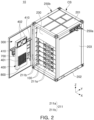
- FIG. 2 is a perspective view of the energy storage system whose door portion 300 is opened.
- FIG. 3 is a perspective view of the battery module 100.
- FIG. 4 is an exemplary view showing that the battery module 100 is inserted into an internal space S of the energy storage system 10.
- FIG. 5 is an exemplary view showing that a guide portion 230 and fixing member of the energy storage system 10 are coupled to each other.
- FIG. 6 is an exemplary view showing a top side of an internal frame in the energy storage system 10.
- the energy storage system 10 and the battery module 100 described with reference to FIGS. 2 through 6 may correspond to the energy storage system 10 and the battery module 100 described with reference to FIG. 1 , and their redundant descriptions may thus be omitted.
- the energy storage system 10 may include the plurality of the battery modules 100 and the cabinet CB in which the battery modules are accommodated.
- the cabinet CB may include the housing 200 having the internal space where the plurality of the battery modules 100 are accommodated, a mounting portion 210 disposed in the housing 200 for the battery module 100 to be mounted thereon, and the door member 300 capable of being opened and closed by being coupled to the housing 200.
- the battery module 100 may include one or more battery cells 110 capable of being charged and discharged to store or emit electrical energy.
- the battery cell 110 included in the battery module 100 may be at least one of a pouch-type secondary battery, a cylindrical secondary battery, and a prismatic secondary battery.
- the battery cells 110 may be stacked in one direction, e.g., in a Y-axis direction.
- the stacking direction shown in FIG. 3 is only an example, and the stacking direction of the battery cells 110 in the battery module 100 may be set in various ways.
- the battery module 100 and the battery cell 110 may be stacked in an X-axis direction or a Z-axis direction.
- the battery module 100 may further include a module cover 120 supporting the stacked battery cells 110.
- the module cover 120 may cover at least a portion of the front surface, rear surface (or a surface perpendicular to a Y-axis) and side surface (or a surface perpendicular to an X-axis) of a stacked body where the battery cells 110 are stacked.
- the top and lower surfaces (or surfaces perpendicular to a Z-axis) of the battery cell 110 may be exposed outward from the battery module 100, or a cooling plate surrounding at least a portion of the battery cell 110 may be exposed outward from the battery module 100.
- the cooling plate may surround at least a portion of the battery cell 110 and may be in contact with the battery cell 110, thus protecting the battery cell 110 from an external impact, and simultaneously emitting heat occurring in the battery cell 110 rapidly outward from the battery module.
- the plurality of battery modules 100 may be stacked in one direction while having a predetermined gap therebetween.
- the battery modules 100 may be inserted into the housing 200 in a first direction (or the Y-axis direction), and stacked in a second direction (or the Z-axis direction) perpendicular to the first direction (or the Y-axis direction).
- the battery modules 100 may be arranged in two rows as shown in FIG. 2 , which is only an example. In another examples, the battery modules 100 may be arranged in one row or three or more rows.
- the housing 200 may be a structure in which the battery module 100 may be accommodated.
- the housing 200 may be a box-shaped member in which a top frame 201, a bottom frame 202, and a plurality of side frames 203 are coupled with one another.
- the housing 200 may have at least one side open, and the battery module 100 may be inserted into the housing 200 through the open one side.
- FIG. 2 shows that the housing 200 has a shape of a hexahedron having one side open, which is only an example, and a specific shape of the housing 200 may be appropriately changed based on a user's need.
- the housing 200 may include a material having predetermined rigidity.
- the housing 200 may include a metal material such as iron, aluminum, or stainless steel.
- the housing 200 may be made of any material as long as the corresponding material has enough rigidity to maintain an external appearance of the housing 200 and protect the battery module 100 in the housing 200.
- the housing 200 may have shape of a cube or rectangular prism.
- the door member 300 may be opened and closed by being coupled to one open side of the housing 200.
- the door member 300 may be hinged to one open side of the housing 200, and the user may thus open and close the door member 300 by pushing or pulling the same.
- each of the energy storage systems 10 may include at least one connection portion 250 used for its electrical connection with another neighboring energy storage system.
- the connection portion 250 of each energy storage systems 10 may include a bar-type member made of a conductive material (e.g., metal), and may be disposed on one side of the housing 200 to be exposed to an external environment.
- connection portion 250 may be electrically connected to the plurality of the battery modules 100 arranged in the housing 200.
- the connection portion 250 may include a first connection portion 250a and a second connection portion 250b which are disposed on opposite sides of the housing 200.
- the first connection portion 250a may be disposed on a first side frame 203 of the housing 200
- the second connection portion 250b may be disposed on a second side frame 203 opposite to the first side frame 203 of the housing 200.
- the first connection portion 250a and the second connection portion 250b may be symmetrical to each other.
- the energy storage system 10 may be electrically connected to other energy storage systems disposed on both sides of the energy storage system 10 through the first connection portion 250a and the second connection portion 250b.
- the battery module 100 may be mounted on the mounting portion 210 disposed in the housing 200.
- the mounting portion 210 may be disposed on an inner surface of the housing 200 while having a shape of a shelf or rail extending in one direction (e.g., the Y-axis direction), and the battery module may be inserted into the housing in an extension direction of the shelf or the rail, and then be fixed into the housing.
- the mounting portion 210 may not be limited to the shape shown in the drawing.
- the mounting portion 210 may have any shape or structure enabling the battery module 100 to be stably disposed in the housing 200.
- the mounting portion 210 may be disposed between the top frame and lower frame of the housing.
- the top frame may configure a top surface of the housing
- the bottom frame may configure a bottom surface of the housing.
- the side frames may respectively be connected to the top frame and the bottom frame to form the side surfaces of the housing.
- the battery module 100 may be coupled to a fixing member 211, and fixed into the housing 200 while being mounted on the mounting portion 210.
- a part of the fixing member 211 may be coupled to the battery module 100, and the other part may be coupled to the housing 200.
- the fixing member 211 may be a bracket mechanically fastened to the battery module 100.
- the fixing member 211 may include a first fixing member 211a and a second fixing member 211b fastened to different portions of the battery module 100.
- the first fixing member 211a and the second fixing member 211b may respectively be coupled to both sides of any one battery module 100.
- the energy storage system 10 may further include the cooling device 400 which may cool the battery module 100 accommodated in the housing 200.
- the cooling device 400 may be coupled to the door member 300.
- the cooling device 400 may cool the battery module 100 by discharging the cooling medium (e.g., cooling air) to the internal space of the housing 200.
- the cooling medium e.g., cooling air
- the cooling device 400 may include a discharge portion 401 through which the cooling medium is discharged, and a suction portion 402 through which the cooling medium discharged from the discharge portion 401 is suctioned and recovered.
- the discharge portion 401 and the suction portion 402 of the cooling device 400 may be disposed on the inside of the door member 300.
- the "inside" of the door member 300 may indicate its part facing the internal space of the housing 200 as the door member 300 is closed.
- the cooling device 400 may be coupled to the door member 300 for the discharge portion 401 and the suction portion 402 to be disposed on the inside of the door member 300. As the door member 300 is closed, the discharge portion 401 and the suction portion 402 may naturally face the battery module 100 accommodated in the internal space of the housing 200.
- the discharge portion 401 and the suction portion 402 may be vertically disposed (in the Z-axis direction).
- the discharge portion 401 through which the cooling medium is discharged may be disposed at a bottom end of the cooling device 400
- the suction portion 402 through which the cooling medium is suctioned may be disposed at a top end of the cooling device 400.
- the cold cooling medium emitted from the discharge portion 401 may flow upward by having a temperature gradually increased through its heat exchange with the battery module 100. Therefore, the cooling medium may implement an efficient cooling flow in the housing 200 by disposing the suction portion 402 above the discharge portion 401.
- the cooling device 400 of the energy storage system 10 may be disposed in the housing 200 to face the battery module 100. Accordingly, the cold cooling medium may be supplied directly from the cooling device 400 to the battery module 100, thus securing cooling efficiency increased compared to a case where the cooling device 400 is disposed on the outside of the housing 200.
- the energy storage system 10 may further include the guide portion 230 which may guide the cooling medium discharged from the cooling device 400 to flow into the housing 200.
- the guide portion 230 may have at least a portion formed in a flat plate shape, and may be disposed on back of the cooling device 400.
- the guide portion 230 may guide a flow path of the cooling medium.
- the guide portion 230 may be disposed between the cooling device 400 and the battery module 100, thus blocking the cold cooling medium discharged from the discharge portion 401 from flowing directly to the suction portion 402. Accordingly, a flow direction of the cold cooling medium discharged from the discharge portion 401 may be guided toward the battery module 100.
- the guide portion 230 may have one surface facing the suction portion 402, and the other surface opposite to the one surface and facing some of the battery modules 100.
- the guide portion 230 may be inclined with respect to the first direction (or the Y-axis direction). For example, referring to Referring to FIG. 2 , as the door member 300 is closed, the cooling device 400 coupled to the door member 300 may face at least some of the battery modules 100 in the first direction (or the Y-axis direction), and at least a portion of the guide portion 230 may be installed in front of the battery module 100 while being inclined in the first direction (or the Y-axis direction).
- the guide portion 230 may be inclined to have a bottom edge closer to the door member 300 than its upper edge. In this case, as the door member 300 is closed, the bottom edge of the guide portion 230 may be adjacent to the cooling device 400.
- the energy storage system 10 may further include an auxiliary guide portion 410 disposed on the door member 300.
- the auxiliary guide portion 410 may guide the flow of the cooling medium together with the guide portion 230.
- the auxiliary guide portion 410 may be disposed on one side of the cooling device 400 and extend horizontally to come into contact with an end of the guide portion 230 as the door member 300 is closed.
- the auxiliary guide portion 410 may block the cooling medium from flowing into a gap between the guide portion 230 and an inner surface of the door member 300. Accordingly, it is possible to more reliably block the cold cooling medium discharged from the discharge portion 401 from flowing directly toward the suction portion 402.
- the auxiliary guide portion 410 may be disposed on one side of the cooling device 400.
- the cooling device 400 may protrude from the inside of the door member 300 while having a predetermined thickness, and the auxiliary guide portions 410 may be disposed on both sides of the cooling device 400 and block the cooling medium from flowing into the gap between the guide portion 230 and the door member 300.
- the auxiliary guide portion 410 may be disposed between the discharge portion 401 and the suction portion 402 of the cooling device 400 based on a height direction (e.g., the Z-axis direction) of the housing 200.
- the battery module 100 or an electronic component 800 in the cabinet CB may be damaged by a flame.
- the electronic component 800 may include various types of sensors including a temperature sensor and a voltage sensor, a signal transmission device, various control devices including a battery management system (BMS), and a circuit board connected thereto.
- BMS battery management system
- the electronic component 800 is not limited to the above component, and may be understood as a general term for an electrical component necessary for the smooth use and maintenance of the energy storage system 10.
- the electronic component 800 may be disposed in the cabinet CB.
- the electronic component 800 may be disposed on the inside of the door member 300 as shown in FIG. 2 .
- the energy storage system 10 may further include a fire extinguishing portion 700 which may extinguish the flame occurring in the cabinet CB.
- the fire extinguishing portion 700 may include a fire extinguishing agent which may suppress the flame, and emit the fire extinguishing agent into the internal space S of the cabinet CB in a fire occurrence situation.
- the fire extinguishing agent may use a variety of the fire extinguishing agents.
- the fire extinguishing agent may include a solid aerosol having a solid form at an operation temperature (or a preset temperature) or less and an aerosol form at the operation temperature (or the preset temperature) or more.
- the aerosol which is the fire extinguishing material, may be generated as the fire extinguishing agent combusts.
- the solid aerosol used as the fire extinguishing agent may include a potassium component to thus block an oxidation chain reaction of the combustion.
- the fire extinguishing portion 700 may be adjacent to the electronic component 800.
- the electronic component 800 may be disposed on the inside of the door member 300, and the fire extinguishing portion 700 may also be disposed on the inside of the door member 300 while being adjacent to the electronic component 800.
- the fire extinguishing portion 700 may be exposed to the internal space S of the housing 200.
- the fire extinguishing agent may be sprayed as aerosol-type particles into the internal space S of the housing 200, and the sprayed aerosol may reach the flame and act as an extinguisher.
- the guide portion 230 or the auxiliary guide portion 410 may minimize a region (or a volume) to be extinguished by the fire extinguishing portion 700.
- the guide portion 230 of the cabinet CB may divide a space between the front surface of the battery module 100 and the door member 300 into two or more spaces, thus reducing a space to be covered by the aerosol sprayed from the fire extinguishing portion 700 for suppressing the fire.
- the guide portion 230 may divide a front space A formed between the battery module 100 and the door member 300 and in contact with the door member 300 into a first region A1 and a second region A2.
- the first region A1 may be a space between a bottom surface of the guide portion 230 and the battery module 100
- the second region A2 may be a space between a top surface of the guide portion 230 and the door member 300.
- the electronic component 800 and the fire extinguishing portion 700 may be disposed in the same region.
- both the electronic component 800 and the fire extinguishing portion 700 may be disposed in the first region A1.
- the fire extinguishing agent of the fire extinguishing portion 700 may be sprayed intensively in the first region A1. Therefore, the fire extinguishing agent may effectively protect the electronic component 800 from the flame.
- the battery module 100 may be inserted into the mounting portion 210 disposed in the housing 200 and accommodated in the internal space S.
- the mounting portion 210 may have the rail shape extending in one direction (e.g., the Y-axis direction) from the inside of the housing 200, and at least a portion of the battery module 100 may thus be mounted thereon.
- the mounting portion 210 may extend in the housing 200 in the first direction (e.g., the Y-axis direction). Accordingly, the battery module 100 may be inserted into the mounting portion 210 in the first direction (or the Y-axis direction).
- an insertion direction of the battery module 100 is not limited thereto.
- the mounting portion 210 of the housing 200 may be inclined with respect to the first direction (or the Y-axis direction). Accordingly, the battery module 100 may be inserted while being inclined with respect to the first direction (or the Y-axis direction).
- the battery module 100 may be accommodated in the plurality of rows.
- FIG. 4 shows that the battery modules 100 are arranged in two rows.
- the housing 200 may further include a partition 204 dividing the internal space S, and the mounting portion 210 may be disposed on each of two sides of the partition 204 for the battery module 100 to be mounted thereon.
- the battery modules 100 may each be supported by the mounting portion 210 and arranged in layers in the height direction (e.g., the Z-axis direction).
- the fixing member 211 fixing the battery module 100 and the mounting portion 210 to each other may be assembled together with the battery module 100.
- the second fixing members 211b may respectively be coupled to the side frame 203 of the housing 200 and the battery module 100
- the first fixing members 211a may be coupled to both the partition 204 and the two battery modules 100.
- the plurality of first fixing members 211a and the plurality of the second fixing members 211b may be provided, and arranged to be parallel to each other in an arrangement direction of the battery modules 100.
- the fixing member 211 may fix the battery module 100 to prevent its separation from the mounting portion 210 in a process of transporting the energy storage system 10.
- the guide portion 230 may be coupled to the housing 200 by being inclined with respect to the first direction (or the Y-axis direction) in a state where the battery module 100 is completely stored on the inside of the mounting portion 210.
- an assembly sequence of the guide portion 230 is not limited thereto.
- the guide portion 230 may be coupled to the housing 200 simultaneously as the battery module 100 is accommodated in and fixed to the housing 200.
- the guide portion 230 may be rotatably coupled to the housing 200 while having its upper edge as an axis. In this case, the guide portion 230 may be rotated upward to secure a space where the battery module 100 is to be inserted, and the battery modules 100 may then be inserted and assembled to each other.
- the guide portion 230 may have one edge adjacent to an internal frame 220.
- the internal frame 220 may be a plate-shaped member fixed to the housing 200 and disposed above the battery module 100, and may face the battery module 100 in the height direction (e.g., the Z-axis direction) of the housing.
- a battery control system (e.g., 221 in FIG. 6 ) of the energy storage system 10 may be disposed on a top surface of the internal frame 220.
- a first edge 231 of the guide portion 230 may be adjacent to the cooling device 400 while the door member 300 is closed, and a second edge 232, which is opposite to the first edge 231, may be coupled to the front of the battery module 100 while being adjacent to the internal frame 220.
- the first edge 231 of the guide portion 230 may be disposed between the discharge portion 401 and the suction portion 402 of the cooling device 400.
- the first edge 231 of the guide portion 230 may be adjacent to an end of the auxiliary guide portion 410 disposed on at least one side of the cooling device 400.
- the guide portion 230 may be inclined with respect to the first direction (or the Y-axis direction). That is, the first edge 231 of the guide portion 230 may be closer to the door member 300 than the second edge 232.
- the energy storage system 10 may be electrically connected to another energy storage system through the connection portion 250.
- connection portion 250 may include one or more first connection members 251 electrically connected to the plurality of the battery modules 100 and an insulating member 252 coupled to the housing 200 and supporting the first connection member 251.
- the first connection member 251 may include the conductive material (e.g., a metal) and may serve as a type of high voltage terminal (or high voltage socket) connected to each of the plurality of the battery modules 100.
- the first connection member 251 may include a power terminal electrically connected to each of the plurality of the battery modules 100.
- the first connection member 251 may have a bar shape extending in one direction.
- the first connection member 251 may be a busbar including the conductive material.
- the first connection member 251 may have one end inserted into the housing 200, and the other end, which is opposite to the one end, exposed outward from the housing 200.
- the first connection member 251 While being inserted into the housing, the first connection member 251 may have at least a portion protruding outward from the housing 200.
- a direction in which the first connection member 251 protrudes outward from the housing 200 may be the third direction (or the X-axis direction) or the direction, perpendicular to the first direction (or the Y-axis direction) in which the battery module 100 is inserted into the mounting portion 210.
- the first connection member 251 may be fixed to the housing 200 while being supported by the insulating member 252.
- the insulating member 252 may surround at least portion of the first connection member 251.
- the insulating member 252 may include a non-conductive material (e.g., plastic) to prevent the first connection member 251 from being electrically short-circuited from the housing 200.
- connection portion 250 may further include a second connection member 253 spaced apart from the first connection member 251.
- the second connection member 253 may perform a function different from that of the first connection member 251.
- the second connection member 253 may be a low-voltage terminal (or low-voltage socket), and may be used for the energy storage system 10 to transmit and receive a signal with an external device.
- the first connection member 251 is used as a direct current connection terminal
- the second connection member 253 may be used as an alternating current connection terminal or an auxiliary power terminal.
- connection portions 250 may be provided in any one energy storage system 10.
- the first connection portion 250a and the second connection portion 250b may respectively be disposed on opposite surfaces of the housing 200.
- each of the first and second connection portions 250a and 250b may include two first connection members 251, and six second connection members 253.
- the housing 200 may include a front surface 200a, a rear surface 200b, a plurality of side surfaces 200c and 200d and a bottom surface 200e. And as illustrated in the embodiment of FIG.1 , FIG. 2 and FIG. 4 , when the door member 300 is disposed on the front surface 200a of the housing 200, the first connecting portion 250a and the second connecting portion 250b may be disposed on both side surfaces 200c and 200d of the housing 200. According to some embodiments, the first connection portion 250a and the second connection portion 250b may be disposed between the top frame 201 of the housing 200 and the battery module 100 based on the height direction (e.g., the Z-axis direction) of the housing 200.
- the height direction e.g., the Z-axis direction
- connection portion 250 may have the plurality of first connection members 251.
- first connection portion 250a disposed on one surface of the housing 200 and the second connection portion 250b disposed on the other surface of the housing 200 may each include the plurality of first connection member 251.
- the plurality of first connection members 251 may have polarities different from each other.
- the first connection portion 250a may have the pair of the first connection members 251 respectively corresponding to a positive electrode and a negative electrode.
- the first connection member 251 of the first connection portion 250a and the first connection member 251 of the second connection portion 250b may protrude in opposite directions.
- the first connection portion 250a of any one energy storage system 10 may face the second connection portion 250b of another neighboring energy storage system 10, thus providing more easier connection between the energy storage systems 10.
- the housing 200 may further include the internal frame 220 disposed above the battery module 100.
- a separation space G where various components electrically connected to the battery module 100 may be disposed may be formed between the internal frame 220 and the top surface of the housing 200.
- connection portion 250 may be disposed on a top side of the internal frame 220. It is possible to prevent a harmful element such as heat, gas, or flame occurring in the battery module 100 from coming into direct contact with the connection portion 250 by separating the connection portion 250 from the space where the battery module 100 is disposed.
- the battery control system 221 and a circulation system 222 may be disposed on the top side of the internal frame 220.
- the battery control system 221 may include the battery management system (BMS) module, a battery protective unit (BPU) module, or the like.
- BMS battery management system
- BPU battery protective unit
- the battery control system 221 may be seated on and assembled to the internal frame 220 and may safely control the battery module 100 disposed under the internal frame 220.
- the circulation system 222 may guide the flow direction of the cooling medium in the separation space G.
- the circulation system 222 may include one or more circulation fans 222a to guide the cooling medium flowing into the separation space G to flow from the rear of the housing 200 to the front.
- the cooling medium may cool the connection portion 250, the battery control system 221, the circulation system 222, and a blocking portion 223 while flowing in the separation space G.
- At least one of the battery control system 221 and the circulation system 222 may receive power by being electrically connected to the external device through the second connection portion 250b.
- at least one of the battery control system 221 and the circulation system 222 may exchange signal information by being electrically connected to the external device through the second connection portion 250b.
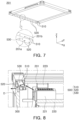
- FIG. 7 is a bottom perspective view of the top frame 201 of the energy storage system.
- FIG. 8 illustrates exemplary flow of the gas occurring in the energy storage system 10.
- the energy storage system 10 described with reference to FIGS. 7 and 8 may include all features of the energy storage system 10 described with reference to FIGS. 1 through 6 , and its redundant description may thus be omitted.
- the energy storage system 10 may include a venting portion 500 which may lower the pressure in the cabinet CB by emitting the gas occurring in the internal space S of the cabinet CB.
- the venting portion 500 may include at least one inlet 510 communicating with the internal space S of the cabinet CB and allowing the gas to flow into the inlet, and at least one outlet 520 allowing the gas flowing into the inlet port 510 to be emitted outward from the cabinet CB.
- the venting portion 500 may be disposed in the top frame 201 of the cabinet CB.
- the inlet 510 may be a hole communicating with the internal space S of the cabinet CB.
- the outlet 520 may be disposed in the outer surface of the cabinet CB, and may be a hole communicating with the inlet 510.
- the gas occurring in the internal space S of the cabinet CB may flow in through the inlet 510 and be emitted outward from the cabinet CB through the outlet 520.
- the plurality of inlets 510 and the plurality of outlets 520 may be provided in the cabinet CB.
- the outlet 520 may be open in a bottom part direction of the cabinet CB (for example, in the negative Z-axis direction of FIG. 7 ).
- the bottom part direction of the cabinet CB may indicate a direction toward the ground when the energy storage system 10 is completely installed at an installation destination.
- the bottom part direction of the cabinet CB may indicate a downward direction based on a gravity direction.
- the bottom part direction of the cabinet CB may indicate a direction from the top frame 201 of the cabinet CB to its lower frame.
- the outlet 520 When open in the above direction, the outlet 520 may prevent rain, snow, or another foreign material in the external environment of the energy storage system 10 from flowing in the energy storage system 10 through the outlet 520.
- a separation space D may be provided between the top frame 201 and the door member 300, and the outlet 520 may communicate with the separation space D.
- the top frame 201 may include a first surface 201a facing the door member 300 in the second direction (or the Z-axis direction), that is, the height direction of the housing 200, and the outlet 520 may be a hole open in the first surface 201a.
- the plurality of outlets 520 may be disposed in the first surface 201a in a third direction (or the X-axis direction) perpendicular to the second direction (or the Z-axis direction).
- the top frame 201 may have a second surface 201b at least partially exposed to the internal space S of the housing 200, and at least one inlet 510 may be disposed in the second surface 201b of the top frame 201.
- the top frame 201 may further include a hollow portion 530 communicating with the inlet 510 and the outlet 520.
- an edge of the top frame 201 may include the hollow portion 530 extending in the third direction (the X-axis direction), and the inlet 510 and the outlet 520 may each communicate with the hollow portion 530.
- the gas occurring in the internal space S of the housing 200 may flow into the hollow portion 530 through the inlet 510 and then be emitted outward from the cabinet CB through the outlet 520.
- the gas occurring in the cabinet CB may be properly emitted outward from the cabinet CB through the venting portion 500. Accordingly, the internal pressure of the cabinet CB may not be increased to a certain level or more, thus preventing the energy storage system 10 from exploding in advance.
- the outlet 520 may be open through the separation space D between the top frame 201 and the door member 300, thereby more effectively preventing rainwater or the foreign material from flowing into the outlet 520 from the outside of the cabinet CB.
- the venting portion may be disposed in a portion of the energy storage system 10 other than the top frame 201 described above.
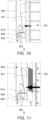
- FIGS. 9 through 11 show a second venting portion 600 disposed in the door member 300 of the energy storage system 10.
- FIG. 9 is an exemplary cross-sectional view of the energy storage system 10.
- FIG. 10 is an exemplary view showing a gas emission structure formed in the door member 300 of the energy storage system.
- FIG. 11 is an exemplary view showing the gas emission structure formed in the door member 300 of the energy storage system.
- the energy storage system 10 described with reference to FIGS. 9 through 11 may include all technical features of the energy storage system 10 described with reference to FIGS. 1 through 8 , and its redundant description may thus be omitted.
- the energy storage system 10 may further include the venting portion 600 disposed in the door member 300.
- the venting portion 600 of the door member 300 may be referred to as the second venting portion 600.
- the second venting portion 600 may include at least one inlet 610 communicating with the internal space S of the cabinet CB to allow the gas to flow into the inlet, and at least one outlet 620 allowing the gas flowing into the inlet port 610 to be emitted outward from the cabinet CB.
- the inlet 610 may be a hole communicating with the internal space S of the cabinet CB.
- the outlet 620 may be disposed in the outer surface of the cabinet CB, and may be a hole communicating with the inlet 610.
- the gas occurring in the internal space S of the cabinet CB may flow in through the inlet 610 and be emitted outward from the cabinet CB through the outlet 620.
- the energy storage system 10 may include a drain pipe 630 for discharging condensate occurring in the cooling device 400, and the inlet 610 and outlet 620 of the second venting portion 600 may communicate with the drain pipe 630.
- the drain pipe 630 may be disposed in the cooling device 400 to discharge the condensate occurring while the cooling device 400 is operated.
- the inlet 610 may be disposed in one end of the drain pipe 630, and the outlet 620 may be disposed in the other end of the drain pipe 630 that is opposite to one end.
- the drain pipe 630 of the cooling device 400 may be used as a gas flow path without a need to generate an additional gas emission structure in the cabinet CB.
- a diameter of the drain pipe 630 may be large enough to allow the gas to be emitted smoothly.
- the drain pipe 630 according to the exemplary embodiments may have a diameter larger than that of a conventional drain pipe functioning as a discharge path of the condensate. Accordingly, both of the gas and the condensate may be discharged smoothly through the drain pipe 630.
- the gas occurring in the internal space S of the housing 200 may flow into the drain pipe 630 through the inlet 610 and then be emitted outward from the cabinet CB through the outlet 620.
- the outlet 620 of the second venting portion 600 may be open to the bottom part direction of the cabinet CB (for example, in the negative Z-axis direction of FIG. 9 ).
- the outlet 620 may be open in this surface.
- the outlet 620 may prevent rain, snow, or another foreign material in the external environment of the energy storage system 10 from flowing in the energy storage system 10 through the outlet 620.
- the energy storage system 10 may include at least one of the venting portion 500 described with reference to FIGS. 7 and 8 and the second venting portion 600 described with reference to FIGS. 9 through 11 .
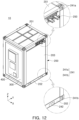
- FIG. 12 is a perspective view of the energy storage system 10.
- the energy storage system 10 described with reference to FIG. 12 may correspond to the energy storage system 10 described above with reference to FIGS. 1 to 11 , and its redundant description may thus be omitted.
- the completely manufactured energy storage system 10 may be picked up by the transport device (for example, the forklift or the crane) and transported to an installation destination.
- the transport device for example, the forklift or the crane
- a plurality of lifting holes 241 and 242 may be disposed in the housing 200 of the energy storage system 10 to be transported by the transport device.
- the first lifting hole 241 may be disposed in the top side or lower side of the housing 200 to be picked up by the crane or the like.
- the second lifting hole 242 may be disposed in the bottom side of the housing 200 for a fork of the forklift, for example, to be inserted into the hole.
- the first lifting hole 241 may be a hole into which the tongs or hook of the crane may be inserted.
- the first lifting hole 241 may be a hole disposed in a corner of the top frame 201 or a corner of the bottom frame 202, and open upward or sideward.
- the second lifting hole 242 may be a hole disposed in the bottom part of the housing 200 for the fork of the forklift to be inserted into the hole.
- the plurality of second lifting holes 242 allowing the fork of a forklift to be inserted into the holes may be disposed in one surface of the bottom frame 202.
- the second lifting hole 242 may be disposed in the side surface of the housing 200 where the door member 300 is not disposed.
- the door member 300 installed with the cooling device 400 may be disposed on one side of the housing 200, and the second lifting hole 242 may be open in a bottom part of the other side surface adjacent to one side of the housing 200.
- the energy storage system 10 may be modularized to be transported in the complete manufacturing state, thus enabling the rapid implementation of the large-capacity energy source at an installation destination.
- the energy storage system 10 may include the venting portions 500 and 600 that may safely emit the gas occurring in the cabinet CB, thereby preventing the energy storage system 10 from exploding due to the internal pressure.
- the energy storage systems according to the exemplary embodiments may rapidly implement the large-capacity energy source at an installation destination.
- the energy storage system may secure the increased stability by safely emitting the gas occurring in the system.
Landscapes
- Chemical & Material Sciences (AREA)
- Chemical Kinetics & Catalysis (AREA)
- General Chemical & Material Sciences (AREA)
- Electrochemistry (AREA)
- Engineering & Computer Science (AREA)
- Manufacturing & Machinery (AREA)
- Emergency Management (AREA)
- Business, Economics & Management (AREA)
- Public Health (AREA)
- Health & Medical Sciences (AREA)
- Battery Mounting, Suspending (AREA)
- Secondary Cells (AREA)
- Gas Exhaust Devices For Batteries (AREA)
Abstract
Description
- Embodiments of the present disclosure relate to an energy storage system.
- An energy storage system (ESS) may be a device or system which may increase overall power usage efficiency by storing power that has already been produced and then supplying the stored power when the power is necessary.
- There is a need for technology that may rapidly manufacture and supply the energy storage systems in accordance with an increasing demand for this energy storage system. In particular, there is a need for an energy storage system to have a portable structure to rapidly install the energy storage system where this system is needed, or to rapidly expand the energy storage system as a necessary power value is increased.
- Meanwhile, a fire may occur in a process of using the energy storage system. In this case, there is a risk of explosion as an internal pressure of the energy storage system is increased due to a gas caused by the fire. Accordingly, there is a need for a structure enabling safe emission of the gas even when the gas occurs in the energy storage system.
- An aspect of the present disclosure may provide an energy storage system modularized and manufactured to be transported in a complete manufacturing state, thus enabling rapid implementation of a large-capacity of an energy source at an installation destination.
- Another aspect of the present disclosure may provide an energy storage system having a structure enabling safe emission of gas occurring in the system.
- According to an aspect of the present disclosure, an energy storage system may include: a cabinet including a mounting portion capable of mounting a plurality of battery modules thereon and a door member capable of being opened and closed; and a venting portion emitting gas occurring in an internal space of the cabinet, wherein the venting portion includes at least one inlet communicating with the internal space and allowing the gas to flow into the inlet; and at least one outlet disposed in an outer surface of the cabinet and communicating with the inlet.
- The cabinet may further include a top frame disposed above the mounting portion and a bottom frame disposed below the mounting portion, and the outlet may be open in the top frame toward the bottom frame.
- The door member may face the mounting portion in a first direction, the top frame may include a first surface facing the door member in a second direction, perpendicular to the first direction, and the outlet may be disposed in the first surface.
- A separation space may be formed between the first surface and the door member, and the outlet may communicate with the separation space.
- The top frame may include a hollow portion communicating with each of the inlet and the outlet.
- The top frame may further include a second surface exposed to the internal space, and the inlet may be disposed in the second surface.
- The at least one inlet or the at least one outlet may be disposed in a third direction, perpendicular to both the first direction and the second direction.
- The door member may further include a cooling device capable of supplying a cooling medium to the internal space, and at least one of the inlet or the outlet may be disposed in the door member.
- The cooling device may include a drain pipe allowing condensate occurring in the cooling device to flow, and the inlet and the outlet may communicate with the drain pipe.
- The inlet may be disposed in one end of the drain pipe, and the outlet may be disposed in the other end of the drain pipe.
- The system may further include: a fire extinguishing portion extinguishing a flame occurring in the internal space of the cabinet; and a guide portion dividing a front space formed between the plurality of battery modules and the door member into a plurality of regions.
- The system may further include an electronic component disposed on the inside of the door member, wherein the fire extinguishing portion and the electronic component are disposed together in one of the plurality of regions divided by the guide portion.
- The fire extinguishing portion may include a fire extinguishing agent maintaining a solid state at a temperature of a preset temperature or less and having an aerosol form at a temperature of the preset temperature or more.
- The cabinet may further include a partition dividing the internal space, and the plurality of battery modules may be disposed on both sides of the partition in a height direction of the cabinet.
- The system may further include a plurality of lifting holes disposed in the cabinet and allowing a transport device to be inserted into the holes.
- The above and other aspects, features and advantages of the present disclosure will be more clearly understood from the following detailed description taken in conjunction with the accompanying drawings, in which:
-
FIG. 1 is an exemplary view showing a plurality of energy storage systems connected to each other according to an embodiment of the present disclosure; -
FIG. 2 is a perspective view of the energy storage system whose door portion is opened according to an embodiment of the present disclosure; -
FIG. 3 is a perspective view of a battery module according to an embodiment of the present disclosure; -
FIG. 4 is an exemplary view showing that the battery module is inserted into an internal space of the energy storage system according to an embodiment of the present disclosure; -
FIG. 5 is an exemplary view showing that the guide portion and fixing member of the energy storage system are coupled to each other according to an embodiment of the present disclosure; -
FIG. 6 is an exemplary view showing a top side of an internal frame in the energy storage system according to an embodiment of the present disclosure; -
FIG. 7 is a bottom perspective view of a top frame of the energy storage system according to an embodiment of the present disclosure; -
FIG. 8 illustrates exemplary flow of a gas occurring in the energy storage system according to an embodiment of the present disclosure; -
FIG. 9 is an exemplary cross-sectional view of the energy storage system according to an embodiment of the present disclosure; -
FIG. 10 is an exemplary view showing a gas emission structure formed in a cooling device of the energy storage system according to an embodiment of the present disclosure; -
FIG. 11 is an exemplary view showing the gas emit structure formed in the cooling device of the energy storage system according to an embodiment of the present disclosure; and -
FIG. 12 is a perspective view of the energy storage system according to an embodiment of the present disclosure. - Prior to the detailed description of the embodiments of the present disclosure, the terms or words used in the specification and claims should not be construed as limited to ordinary or dictionary meanings, and should be interpreted as having a meaning and concept consistent with the technical idea of the present disclosure based on the principle that the inventor may appropriately define the concept of the terms or words to describe his/her invention in the best way.
- The same reference numerals or symbols in each drawing attached to the specification indicate parts or components that perform substantially the same function. For convenience of description and understanding, even different embodiments may be described using the same reference numerals or symbols. That is, even if components having the same reference number are shown in a plurality of drawings, the plurality of drawings do not all represent one embodiment.
- In the following description, singular expressions include plural expressions unless the context clearly dictates otherwise. It should be understood that terms such as "include" or "comprise" are intended to designate the presence of features, numbers, steps, operations, components, parts, or combinations thereof described in the specification, and do not exclude in advance the possibility of the presence or addition of one or more other features or numbers, steps, operations, components, parts, or combinations thereof.
- In addition, in the following description, expressions such as top portion, bottom portion, side surface, front surface, rear surface, etc. are expressed based on the direction shown in the drawing, and it should be noted in advance that when the direction of the corresponding object is changed, expressions may be expressed differently.
- In addition, in the specification and claims, terms including ordinal numbers such as "first", "second", etc. may be used to distinguish components. These ordinal numbers are used to distinguish identical or similar components from each other, and the meaning of the term should not be interpreted limitedly due to the use of these ordinal numbers. For example, a component combined with the ordinal number should not be interpreted as limiting the order of use or arrangement by the number. If necessary, the ordinal numbers may be used interchangeably.
- Hereinafter, embodiments of the present disclosure will be described with reference to the attached drawings. However, the spirit of the present disclosure is not limited to the presented embodiments of the present disclosure. For example, a person skilled in the art who understands the spirit of the present disclosure may suggest other embodiments that are included within the scope of the spirit of the present disclosure through addition, change, or deletion of components, but this may be also included within the scope of the spirit of the present disclosure. The shapes and sizes of components in the drawings may be exaggerated for clearer description.
- Hereinafter, exemplary embodiments of the present disclosure will now be described in detail with reference to the accompanying drawings.
-
FIG. 1 is an exemplarily view showing a plurality ofenergy storage systems 10 connected to each other. - The
energy storage system 10 may be an energy source and used for home or industrial purpose. The plurality ofenergy storage systems 10 may be electrically connected to each other as shown inFIG. 1 . - Any one of the
energy storage system 10 may include a cabinet CB where a battery module (100 inFIGS. 2 and3 for example) is stored. - The cabinet CB may include a
housing 200 having an internal space where thebattery module 100 is stored and at least one side open, and adoor member 300 capable of being opened and closed by being coupled to thehousing 200 and capable of closing the internal space. - A
cooling device 400 may be disposed on thedoor member 300. Thecooling device 400 may supply a cooling medium into thehousing 200. As another example, thecooling device 400 may suction the cooling medium inside thehousing 200. The cooling medium may indicate a gas or a fluid which may cool the internal space of thehousing 200 and components disposed in the internal space (e.g., the battery modules (100 inFIG. 2 )). - For example, the
cooling device 400 may include an air conditioning device which may control the temperature and humidity of the internal space of thehousing 200 for the battery module (100 inFIG. 2 ) to be operated in an appropriate environment. - In exemplary embodiments, each
energy storage system 10 may include one ormore cooling portions 400. For example, as shown inFIG. 1 , each coolingportion 400 may be disposed individually in the cabinet CB of theenergy storage system 10. - In this way, the
individual cooling portion 400 may be disposed in each of theenergy storage system 10, and eachenergy storage system 10 may be cooled independently. For example, an event (e.g., a phenomenon where a temperature inside or outside the battery module is increased to a safe temperature or more) may occur in any one of the plurality ofenergy storage systems 10. In this case, thecooling device 400 of theenergy storage system 10 may supply the cooling medium with a higher output to thus rapidly control the event. Hence, having thecooling device 400 individually in each of theenergy storage system 10 allows faster and better temperature control of eachenergy storage system 10 and may prevent overheating of theenergy storage system 10 more efficiently. - The output of the
cooling device 400 may be adjusted in various ways in response to a temperature of eachenergy storage system 10, thus increasing cooling efficiency of an entire system including the plurality ofenergy storage systems 10. - The
energy storage system 10 according to the exemplary embodiments may be movable. For example, theenergy storage system 10 may be manufactured as a complete product into which the battery module (100 inFIG. 2 for example) is stored and fixed, and then be moved to its installation site by using a transport device (for example, a forklift or a crane). - Accordingly, the plurality of
energy storage systems 10 may be manufactured repeatedly in a factory, a required number of energy storage systems may be transported to the installation site, and then be electrically connected to each other, thereby rapidly implementing an energy source of a capacity desired by a user. - The plurality of
energy storage systems 10 may be electrically connected to each other through a connection portion. For example, referring toFIG. 1 , the connection portion may be exposed to one surface of the cabinet CB included in any oneenergy storage system 10, and this connection portion may be connected to the connection portion of another neighboringenergy storage system 10. In this way, the plurality ofenergy storage systems 10 may be electrically connected to each other to thus implement a large-capacity energy source. - Hereinafter, the configuration of the
energy storage system 10 is described in more detail with reference toFIGS. 2 through 6 . -
FIG. 2 is a perspective view of the energy storage system whosedoor portion 300 is opened. -
FIG. 3 is a perspective view of thebattery module 100. -
FIG. 4 is an exemplary view showing that thebattery module 100 is inserted into an internal space S of theenergy storage system 10. -
FIG. 5 is an exemplary view showing that aguide portion 230 and fixing member of theenergy storage system 10 are coupled to each other. -
FIG. 6 is an exemplary view showing a top side of an internal frame in theenergy storage system 10. - The
energy storage system 10 and thebattery module 100 described with reference toFIGS. 2 through 6 may correspond to theenergy storage system 10 and thebattery module 100 described with reference toFIG. 1 , and their redundant descriptions may thus be omitted. - The
energy storage system 10 may include the plurality of thebattery modules 100 and the cabinet CB in which the battery modules are accommodated. - The cabinet CB may include the
housing 200 having the internal space where the plurality of thebattery modules 100 are accommodated, a mountingportion 210 disposed in thehousing 200 for thebattery module 100 to be mounted thereon, and thedoor member 300 capable of being opened and closed by being coupled to thehousing 200. - Referring to
FIG. 3 , thebattery module 100 may include one ormore battery cells 110 capable of being charged and discharged to store or emit electrical energy. For example, thebattery cell 110 included in thebattery module 100 may be at least one of a pouch-type secondary battery, a cylindrical secondary battery, and a prismatic secondary battery. - Referring to
FIG. 3 , in thebattery module 100, thebattery cells 110 may be stacked in one direction, e.g., in a Y-axis direction. However, the stacking direction shown inFIG. 3 is only an example, and the stacking direction of thebattery cells 110 in thebattery module 100 may be set in various ways. For example, thebattery module 100 and thebattery cell 110 may be stacked in an X-axis direction or a Z-axis direction. - The
battery module 100 may further include amodule cover 120 supporting the stackedbattery cells 110. For example, as shown inFIG. 3 , themodule cover 120 may cover at least a portion of the front surface, rear surface (or a surface perpendicular to a Y-axis) and side surface (or a surface perpendicular to an X-axis) of a stacked body where thebattery cells 110 are stacked. In this case, the top and lower surfaces (or surfaces perpendicular to a Z-axis) of thebattery cell 110 may be exposed outward from thebattery module 100, or a cooling plate surrounding at least a portion of thebattery cell 110 may be exposed outward from thebattery module 100. For example, the cooling plate may surround at least a portion of thebattery cell 110 and may be in contact with thebattery cell 110, thus protecting thebattery cell 110 from an external impact, and simultaneously emitting heat occurring in thebattery cell 110 rapidly outward from the battery module. - Referring to
FIG. 2 , in thehousing 200, the plurality ofbattery modules 100 may be stacked in one direction while having a predetermined gap therebetween. For example, referring toFIG. 2 , thebattery modules 100 may be inserted into thehousing 200 in a first direction (or the Y-axis direction), and stacked in a second direction (or the Z-axis direction) perpendicular to the first direction (or the Y-axis direction). - In the
housing 200, thebattery modules 100 may be arranged in two rows as shown inFIG. 2 , which is only an example. In another examples, thebattery modules 100 may be arranged in one row or three or more rows. - The
housing 200 may be a structure in which thebattery module 100 may be accommodated. - The
housing 200 may be a box-shaped member in which atop frame 201, abottom frame 202, and a plurality of side frames 203 are coupled with one another. - The
housing 200 may have at least one side open, and thebattery module 100 may be inserted into thehousing 200 through the open one side.FIG. 2 shows that thehousing 200 has a shape of a hexahedron having one side open, which is only an example, and a specific shape of thehousing 200 may be appropriately changed based on a user's need. - The
housing 200 may include a material having predetermined rigidity. For example, thehousing 200 may include a metal material such as iron, aluminum, or stainless steel. However, in addition to the metal, thehousing 200 may be made of any material as long as the corresponding material has enough rigidity to maintain an external appearance of thehousing 200 and protect thebattery module 100 in thehousing 200. For example, thehousing 200 may have shape of a cube or rectangular prism. - The
door member 300 may be opened and closed by being coupled to one open side of thehousing 200. For example, thedoor member 300 may be hinged to one open side of thehousing 200, and the user may thus open and close thedoor member 300 by pushing or pulling the same. - In each of the
energy storage systems 10 may include at least oneconnection portion 250 used for its electrical connection with another neighboring energy storage system. For example, theconnection portion 250 of eachenergy storage systems 10 may include a bar-type member made of a conductive material (e.g., metal), and may be disposed on one side of thehousing 200 to be exposed to an external environment. - The
connection portion 250 may be electrically connected to the plurality of thebattery modules 100 arranged in thehousing 200. - The
connection portion 250 may include afirst connection portion 250a and asecond connection portion 250b which are disposed on opposite sides of thehousing 200. For example, referring toFIG. 2 , thefirst connection portion 250a may be disposed on afirst side frame 203 of thehousing 200, and thesecond connection portion 250b may be disposed on asecond side frame 203 opposite to thefirst side frame 203 of thehousing 200. - The
first connection portion 250a and thesecond connection portion 250b may be symmetrical to each other. - The
energy storage system 10 may be electrically connected to other energy storage systems disposed on both sides of theenergy storage system 10 through thefirst connection portion 250a and thesecond connection portion 250b. - The
battery module 100 may be mounted on the mountingportion 210 disposed in thehousing 200. For example, the mountingportion 210 may be disposed on an inner surface of thehousing 200 while having a shape of a shelf or rail extending in one direction (e.g., the Y-axis direction), and the battery module may be inserted into the housing in an extension direction of the shelf or the rail, and then be fixed into the housing. - However, a specific shape of the mounting
portion 210 may not be limited to the shape shown in the drawing. The mountingportion 210 may have any shape or structure enabling thebattery module 100 to be stably disposed in thehousing 200. - The mounting
portion 210 may be disposed between the top frame and lower frame of the housing. The top frame may configure a top surface of the housing, and the bottom frame may configure a bottom surface of the housing. The side frames may respectively be connected to the top frame and the bottom frame to form the side surfaces of the housing. - The
battery module 100 may be coupled to a fixingmember 211, and fixed into thehousing 200 while being mounted on the mountingportion 210. A part of the fixingmember 211 may be coupled to thebattery module 100, and the other part may be coupled to thehousing 200. For example, the fixingmember 211 may be a bracket mechanically fastened to thebattery module 100. - The fixing
member 211 may include afirst fixing member 211a and asecond fixing member 211b fastened to different portions of thebattery module 100. For example, referring toFIG. 2 , the first fixingmember 211a and the second fixingmember 211b may respectively be coupled to both sides of any onebattery module 100. - The
energy storage system 10 may further include thecooling device 400 which may cool thebattery module 100 accommodated in thehousing 200. For example, referring toFIG. 2 , thecooling device 400 may be coupled to thedoor member 300. - The
cooling device 400 may cool thebattery module 100 by discharging the cooling medium (e.g., cooling air) to the internal space of thehousing 200. - The
cooling device 400 may include adischarge portion 401 through which the cooling medium is discharged, and asuction portion 402 through which the cooling medium discharged from thedischarge portion 401 is suctioned and recovered. - The
discharge portion 401 and thesuction portion 402 of thecooling device 400 may be disposed on the inside of thedoor member 300. Here, the "inside" of thedoor member 300 may indicate its part facing the internal space of thehousing 200 as thedoor member 300 is closed. - For example, as shown in
FIG. 2 , thecooling device 400 may be coupled to thedoor member 300 for thedischarge portion 401 and thesuction portion 402 to be disposed on the inside of thedoor member 300. As thedoor member 300 is closed, thedischarge portion 401 and thesuction portion 402 may naturally face thebattery module 100 accommodated in the internal space of thehousing 200. - In the
cooling device 400, thedischarge portion 401 and thesuction portion 402 may be vertically disposed (in the Z-axis direction). For example, thedischarge portion 401 through which the cooling medium is discharged may be disposed at a bottom end of thecooling device 400, and thesuction portion 402 through which the cooling medium is suctioned may be disposed at a top end of thecooling device 400. The cold cooling medium emitted from thedischarge portion 401 may flow upward by having a temperature gradually increased through its heat exchange with thebattery module 100. Therefore, the cooling medium may implement an efficient cooling flow in thehousing 200 by disposing thesuction portion 402 above thedischarge portion 401. - In the exemplary embodiments, the
cooling device 400 of theenergy storage system 10 may be disposed in thehousing 200 to face thebattery module 100. Accordingly, the cold cooling medium may be supplied directly from thecooling device 400 to thebattery module 100, thus securing cooling efficiency increased compared to a case where thecooling device 400 is disposed on the outside of thehousing 200. - The
energy storage system 10 may further include theguide portion 230 which may guide the cooling medium discharged from thecooling device 400 to flow into thehousing 200. For example, referring toFIG. 2 , theguide portion 230 may have at least a portion formed in a flat plate shape, and may be disposed on back of thecooling device 400. - The
guide portion 230 may guide a flow path of the cooling medium. For example, theguide portion 230 may be disposed between the coolingdevice 400 and thebattery module 100, thus blocking the cold cooling medium discharged from thedischarge portion 401 from flowing directly to thesuction portion 402. Accordingly, a flow direction of the cold cooling medium discharged from thedischarge portion 401 may be guided toward thebattery module 100. - The
guide portion 230 may have one surface facing thesuction portion 402, and the other surface opposite to the one surface and facing some of thebattery modules 100. - When defining a direction in which the
cooling device 400 and thebattery module 100 face each other as the first direction (or the Y-axis direction), theguide portion 230 may be inclined with respect to the first direction (or the Y-axis direction). For example, referring to Referring toFIG. 2 , as thedoor member 300 is closed, thecooling device 400 coupled to thedoor member 300 may face at least some of thebattery modules 100 in the first direction (or the Y-axis direction), and at least a portion of theguide portion 230 may be installed in front of thebattery module 100 while being inclined in the first direction (or the Y-axis direction). - Referring to
FIG. 2 , theguide portion 230 may be inclined to have a bottom edge closer to thedoor member 300 than its upper edge. In this case, as thedoor member 300 is closed, the bottom edge of theguide portion 230 may be adjacent to thecooling device 400. - According to some embodiments, the
energy storage system 10 may further include anauxiliary guide portion 410 disposed on thedoor member 300. Theauxiliary guide portion 410 may guide the flow of the cooling medium together with theguide portion 230. - For example, referring to
FIG. 2 , theauxiliary guide portion 410 may be disposed on one side of thecooling device 400 and extend horizontally to come into contact with an end of theguide portion 230 as thedoor member 300 is closed. Theauxiliary guide portion 410 may block the cooling medium from flowing into a gap between theguide portion 230 and an inner surface of thedoor member 300. Accordingly, it is possible to more reliably block the cold cooling medium discharged from thedischarge portion 401 from flowing directly toward thesuction portion 402. - In the exemplary embodiments, the
auxiliary guide portion 410 may be disposed on one side of thecooling device 400. For example, referring toFIG. 2 , thecooling device 400 may protrude from the inside of thedoor member 300 while having a predetermined thickness, and theauxiliary guide portions 410 may be disposed on both sides of thecooling device 400 and block the cooling medium from flowing into the gap between theguide portion 230 and thedoor member 300. - The
auxiliary guide portion 410 may be disposed between thedischarge portion 401 and thesuction portion 402 of thecooling device 400 based on a height direction (e.g., the Z-axis direction) of thehousing 200. - If a fire occurs in the cabinet CB, there is a risk that the
battery module 100 or anelectronic component 800 in the cabinet CB may be damaged by a flame. Examples of theelectronic component 800 may include various types of sensors including a temperature sensor and a voltage sensor, a signal transmission device, various control devices including a battery management system (BMS), and a circuit board connected thereto. However, theelectronic component 800 is not limited to the above component, and may be understood as a general term for an electrical component necessary for the smooth use and maintenance of theenergy storage system 10. - The
electronic component 800 may be disposed in the cabinet CB. For example, theelectronic component 800 may be disposed on the inside of thedoor member 300 as shown inFIG. 2 . - It is necessary to extinguish the fire rapidly to prevent the
electronic component 800 from being damaged by the fire. To this end, theenergy storage system 10 may further include afire extinguishing portion 700 which may extinguish the flame occurring in the cabinet CB. - The
fire extinguishing portion 700 may include a fire extinguishing agent which may suppress the flame, and emit the fire extinguishing agent into the internal space S of the cabinet CB in a fire occurrence situation. - The fire extinguishing agent may use a variety of the fire extinguishing agents. For example, the fire extinguishing agent may include a solid aerosol having a solid form at an operation temperature (or a preset temperature) or less and an aerosol form at the operation temperature (or the preset temperature) or more. Accordingly, in the fire situation, the aerosol, which is the fire extinguishing material, may be generated as the fire extinguishing agent combusts. For example, the solid aerosol used as the fire extinguishing agent may include a potassium component to thus block an oxidation chain reaction of the combustion.
- The
fire extinguishing portion 700 may be adjacent to theelectronic component 800. For example, referring toFIG. 2 , theelectronic component 800 may be disposed on the inside of thedoor member 300, and thefire extinguishing portion 700 may also be disposed on the inside of thedoor member 300 while being adjacent to theelectronic component 800. - As the
door member 300 closes the internal space S of thehousing 200, at least a portion of thefire extinguishing portion 700 may be exposed to the internal space S of thehousing 200. When the fire occurs, the fire extinguishing agent may be sprayed as aerosol-type particles into the internal space S of thehousing 200, and the sprayed aerosol may reach the flame and act as an extinguisher. - The
guide portion 230 or theauxiliary guide portion 410 may minimize a region (or a volume) to be extinguished by thefire extinguishing portion 700. For example, theguide portion 230 of the cabinet CB may divide a space between the front surface of thebattery module 100 and thedoor member 300 into two or more spaces, thus reducing a space to be covered by the aerosol sprayed from thefire extinguishing portion 700 for suppressing the fire. - For example, referring to
FIG. 6 , theguide portion 230 may divide a front space A formed between thebattery module 100 and thedoor member 300 and in contact with thedoor member 300 into a first region A1 and a second region A2. The first region A1 may be a space between a bottom surface of theguide portion 230 and thebattery module 100, and the second region A2 may be a space between a top surface of theguide portion 230 and thedoor member 300. - Here, the
electronic component 800 and thefire extinguishing portion 700 may be disposed in the same region. For example, both theelectronic component 800 and thefire extinguishing portion 700 may be disposed in the first region A1. In this case, the fire extinguishing agent of thefire extinguishing portion 700 may be sprayed intensively in the first region A1. Therefore, the fire extinguishing agent may effectively protect theelectronic component 800 from the flame. - Referring to
FIG. 4 , thebattery module 100 may be inserted into the mountingportion 210 disposed in thehousing 200 and accommodated in the internal space S. The mountingportion 210 may have the rail shape extending in one direction (e.g., the Y-axis direction) from the inside of thehousing 200, and at least a portion of thebattery module 100 may thus be mounted thereon. - For example, referring to
FIGS. 4 and5 , the mountingportion 210 may extend in thehousing 200 in the first direction (e.g., the Y-axis direction). Accordingly, thebattery module 100 may be inserted into the mountingportion 210 in the first direction (or the Y-axis direction). However, an insertion direction of thebattery module 100 is not limited thereto. For example, the mountingportion 210 of thehousing 200 may be inclined with respect to the first direction (or the Y-axis direction). Accordingly, thebattery module 100 may be inserted while being inclined with respect to the first direction (or the Y-axis direction). - In the
housing 200, thebattery module 100 may be accommodated in the plurality of rows. For example,FIG. 4 shows that thebattery modules 100 are arranged in two rows. Thehousing 200 may further include a partition 204 dividing the internal space S, and the mountingportion 210 may be disposed on each of two sides of the partition 204 for thebattery module 100 to be mounted thereon. - The
battery modules 100 may each be supported by the mountingportion 210 and arranged in layers in the height direction (e.g., the Z-axis direction). - In a process of accommodating the
battery module 100 in the mountingportion 210, the fixingmember 211 fixing thebattery module 100 and the mountingportion 210 to each other may be assembled together with thebattery module 100. For example, thesecond fixing members 211b may respectively be coupled to theside frame 203 of thehousing 200 and thebattery module 100, and thefirst fixing members 211a may be coupled to both the partition 204 and the twobattery modules 100. - The plurality of
first fixing members 211a and the plurality of thesecond fixing members 211b may be provided, and arranged to be parallel to each other in an arrangement direction of thebattery modules 100. - The fixing
member 211 may fix thebattery module 100 to prevent its separation from the mountingportion 210 in a process of transporting theenergy storage system 10. - The
guide portion 230 may be coupled to thehousing 200 by being inclined with respect to the first direction (or the Y-axis direction) in a state where thebattery module 100 is completely stored on the inside of the mountingportion 210. However, an assembly sequence of theguide portion 230 is not limited thereto. For example, theguide portion 230 may be coupled to thehousing 200 simultaneously as thebattery module 100 is accommodated in and fixed to thehousing 200. Alternatively, theguide portion 230 may be rotatably coupled to thehousing 200 while having its upper edge as an axis. In this case, theguide portion 230 may be rotated upward to secure a space where thebattery module 100 is to be inserted, and thebattery modules 100 may then be inserted and assembled to each other. - In the exemplary embodiments, the
guide portion 230 may have one edge adjacent to aninternal frame 220. Theinternal frame 220 may be a plate-shaped member fixed to thehousing 200 and disposed above thebattery module 100, and may face thebattery module 100 in the height direction (e.g., the Z-axis direction) of the housing. A battery control system (e.g., 221 inFIG. 6 ) of theenergy storage system 10 may be disposed on a top surface of theinternal frame 220. - Referring to
FIGS. 4 and5 , afirst edge 231 of theguide portion 230 may be adjacent to thecooling device 400 while thedoor member 300 is closed, and asecond edge 232, which is opposite to thefirst edge 231, may be coupled to the front of thebattery module 100 while being adjacent to theinternal frame 220. - While the
door member 300 is closed, thefirst edge 231 of theguide portion 230 may be disposed between thedischarge portion 401 and thesuction portion 402 of thecooling device 400. In addition, thefirst edge 231 of theguide portion 230 may be adjacent to an end of theauxiliary guide portion 410 disposed on at least one side of thecooling device 400. - The
guide portion 230 may be inclined with respect to the first direction (or the Y-axis direction). That is, thefirst edge 231 of theguide portion 230 may be closer to thedoor member 300 than thesecond edge 232. - The
energy storage system 10 may be electrically connected to another energy storage system through theconnection portion 250. - Any one
connection portion 250 may include one or morefirst connection members 251 electrically connected to the plurality of thebattery modules 100 and an insulatingmember 252 coupled to thehousing 200 and supporting thefirst connection member 251. - The
first connection member 251 may include the conductive material (e.g., a metal) and may serve as a type of high voltage terminal (or high voltage socket) connected to each of the plurality of thebattery modules 100. For example, thefirst connection member 251 may include a power terminal electrically connected to each of the plurality of thebattery modules 100. - The
first connection member 251 may have a bar shape extending in one direction. For example, thefirst connection member 251 may be a busbar including the conductive material. Thefirst connection member 251 may have one end inserted into thehousing 200, and the other end, which is opposite to the one end, exposed outward from thehousing 200. - While being inserted into the housing, the
first connection member 251 may have at least a portion protruding outward from thehousing 200. Here, a direction in which thefirst connection member 251 protrudes outward from thehousing 200 may be the third direction (or the X-axis direction) or the direction, perpendicular to the first direction (or the Y-axis direction) in which thebattery module 100 is inserted into the mountingportion 210. - The
first connection member 251 may be fixed to thehousing 200 while being supported by the insulatingmember 252. The insulatingmember 252 may surround at least portion of thefirst connection member 251. The insulatingmember 252 may include a non-conductive material (e.g., plastic) to prevent thefirst connection member 251 from being electrically short-circuited from thehousing 200. - The
connection portion 250 may further include asecond connection member 253 spaced apart from thefirst connection member 251. - The
second connection member 253 may perform a function different from that of thefirst connection member 251. For example, thesecond connection member 253 may be a low-voltage terminal (or low-voltage socket), and may be used for theenergy storage system 10 to transmit and receive a signal with an external device. Alternatively, when thefirst connection member 251 is used as a direct current connection terminal, thesecond connection member 253 may be used as an alternating current connection terminal or an auxiliary power terminal. - The plurality of
connection portions 250 may be provided in any oneenergy storage system 10. Thefirst connection portion 250a and thesecond connection portion 250b may respectively be disposed on opposite surfaces of thehousing 200. - When the
door member 300 is disposed on the front surface of thehousing 200, thefirst connection portion 250a and thesecond connection portion 250b may be disposed on both the side surfaces of thehousing 200. Thefirst connection portion 250a and thesecond connection portion 250b may be disposed to avoid thedoor member 300, thus avoiding interference of thedoor member 300 with thefirst connection portion 250a and thesecond connection portion 250b in a process of opening and closing thedoor member 300. Also, as an example, as illustrated in the embodiment ofFIG.1 ,FIG. 2 andFIG. 4 , each of the first andsecond connection portions first connection members 251, and sixsecond connection members 253. - According to some embodiments, as illustrated in the embodiment of
FIG.1 , thehousing 200 may include afront surface 200a, arear surface 200b, a plurality of side surfaces 200c and 200d and abottom surface 200e. And as illustrated in the embodiment ofFIG.1 ,FIG. 2 andFIG. 4 , when thedoor member 300 is disposed on thefront surface 200a of thehousing 200, the first connectingportion 250a and the second connectingportion 250b may be disposed on both side surfaces 200c and 200d of thehousing 200. According to some embodiments, thefirst connection portion 250a and thesecond connection portion 250b may be disposed between thetop frame 201 of thehousing 200 and thebattery module 100 based on the height direction (e.g., the Z-axis direction) of thehousing 200. - Any one
connection portion 250 may have the plurality offirst connection members 251. For example, thefirst connection portion 250a disposed on one surface of thehousing 200 and thesecond connection portion 250b disposed on the other surface of thehousing 200 may each include the plurality offirst connection member 251. - In any one
connection portion 250, the plurality offirst connection members 251 may have polarities different from each other. For example, thefirst connection portion 250a may have the pair of thefirst connection members 251 respectively corresponding to a positive electrode and a negative electrode. - In any one
energy storage system 10, thefirst connection member 251 of thefirst connection portion 250a and thefirst connection member 251 of thesecond connection portion 250b may protrude in opposite directions. Through this structure, thefirst connection portion 250a of any oneenergy storage system 10 may face thesecond connection portion 250b of another neighboringenergy storage system 10, thus providing more easier connection between theenergy storage systems 10. - The
housing 200 may further include theinternal frame 220 disposed above thebattery module 100. A separation space G where various components electrically connected to thebattery module 100 may be disposed may be formed between theinternal frame 220 and the top surface of thehousing 200. - The
connection portion 250 may be disposed on a top side of theinternal frame 220. It is possible to prevent a harmful element such as heat, gas, or flame occurring in thebattery module 100 from coming into direct contact with theconnection portion 250 by separating theconnection portion 250 from the space where thebattery module 100 is disposed. - In addition, the
battery control system 221 and acirculation system 222 may be disposed on the top side of theinternal frame 220. Thebattery control system 221 may include the battery management system (BMS) module, a battery protective unit (BPU) module, or the like. Thebattery control system 221 may be seated on and assembled to theinternal frame 220 and may safely control thebattery module 100 disposed under theinternal frame 220. - The
circulation system 222 may guide the flow direction of the cooling medium in the separation space G. For example, thecirculation system 222 may include one or more circulation fans 222a to guide the cooling medium flowing into the separation space G to flow from the rear of thehousing 200 to the front. The cooling medium may cool theconnection portion 250, thebattery control system 221, thecirculation system 222, and a blockingportion 223 while flowing in the separation space G. - At least one of the
battery control system 221 and thecirculation system 222 may receive power by being electrically connected to the external device through thesecond connection portion 250b. Alternatively, at least one of thebattery control system 221 and thecirculation system 222 may exchange signal information by being electrically connected to the external device through thesecond connection portion 250b. -
FIG. 7 is a bottom perspective view of thetop frame 201 of the energy storage system.FIG. 8 illustrates exemplary flow of the gas occurring in theenergy storage system 10. - The
energy storage system 10 described with reference toFIGS. 7 and 8 may include all features of theenergy storage system 10 described with reference toFIGS. 1 through 6 , and its redundant description may thus be omitted. - If the fire occurs in the
energy storage system 10, there is a risk that the cabinet CB explodes due to its internal pressure increased by the gas caused by the fire. In addition, there is a risk of injury to the user when thedoor member 300 is opened while the internal pressure is increased. To prevent this risk, theenergy storage system 10 may include a ventingportion 500 which may lower the pressure in the cabinet CB by emitting the gas occurring in the internal space S of the cabinet CB. - The venting
portion 500 may include at least oneinlet 510 communicating with the internal space S of the cabinet CB and allowing the gas to flow into the inlet, and at least oneoutlet 520 allowing the gas flowing into theinlet port 510 to be emitted outward from the cabinet CB. - For example, referring to
FIGS. 7 and 8 , the ventingportion 500 may be disposed in thetop frame 201 of the cabinet CB. - The
inlet 510 may be a hole communicating with the internal space S of the cabinet CB. Theoutlet 520 may be disposed in the outer surface of the cabinet CB, and may be a hole communicating with theinlet 510. The gas occurring in the internal space S of the cabinet CB may flow in through theinlet 510 and be emitted outward from the cabinet CB through theoutlet 520. - The plurality of
inlets 510 and the plurality ofoutlets 520 may be provided in the cabinet CB. - The
outlet 520 may be open in a bottom part direction of the cabinet CB (for example, in the negative Z-axis direction ofFIG. 7 ). Here, "the bottom part direction of the cabinet CB" may indicate a direction toward the ground when theenergy storage system 10 is completely installed at an installation destination. Alternatively, "the bottom part direction of the cabinet CB" may indicate a downward direction based on a gravity direction. Alternatively, "the bottom part direction of the cabinet CB" may indicate a direction from thetop frame 201 of the cabinet CB to its lower frame. - When open in the above direction, the
outlet 520 may prevent rain, snow, or another foreign material in the external environment of theenergy storage system 10 from flowing in theenergy storage system 10 through theoutlet 520. - In the exemplary embodiments, a separation space D may be provided between the
top frame 201 and thedoor member 300, and theoutlet 520 may communicate with the separation space D. - For example, referring to
FIG. 8 , thetop frame 201 may include afirst surface 201a facing thedoor member 300 in the second direction (or the Z-axis direction), that is, the height direction of thehousing 200, and theoutlet 520 may be a hole open in thefirst surface 201a. - The plurality of
outlets 520 may be disposed in thefirst surface 201a in a third direction (or the X-axis direction) perpendicular to the second direction (or the Z-axis direction). - The
top frame 201 may have asecond surface 201b at least partially exposed to the internal space S of thehousing 200, and at least oneinlet 510 may be disposed in thesecond surface 201b of thetop frame 201. - The
top frame 201 may further include ahollow portion 530 communicating with theinlet 510 and theoutlet 520. For example, referring toFIG. 8 , an edge of thetop frame 201 may include thehollow portion 530 extending in the third direction (the X-axis direction), and theinlet 510 and theoutlet 520 may each communicate with thehollow portion 530. The gas occurring in the internal space S of thehousing 200 may flow into thehollow portion 530 through theinlet 510 and then be emitted outward from the cabinet CB through theoutlet 520. - In this way, the gas occurring in the cabinet CB may be properly emitted outward from the cabinet CB through the venting
portion 500. Accordingly, the internal pressure of the cabinet CB may not be increased to a certain level or more, thus preventing theenergy storage system 10 from exploding in advance. - In addition, the
outlet 520 may be open through the separation space D between thetop frame 201 and thedoor member 300, thereby more effectively preventing rainwater or the foreign material from flowing into theoutlet 520 from the outside of the cabinet CB. - Meanwhile, in the
energy storage system 10, the venting portion may be disposed in a portion of theenergy storage system 10 other than thetop frame 201 described above. For example,FIGS. 9 through 11 show asecond venting portion 600 disposed in thedoor member 300 of theenergy storage system 10. -
FIG. 9 is an exemplary cross-sectional view of theenergy storage system 10.FIG. 10 is an exemplary view showing a gas emission structure formed in thedoor member 300 of the energy storage system.FIG. 11 is an exemplary view showing the gas emission structure formed in thedoor member 300 of the energy storage system. - The
energy storage system 10 described with reference toFIGS. 9 through 11 may include all technical features of theenergy storage system 10 described with reference toFIGS. 1 through 8 , and its redundant description may thus be omitted. - The
energy storage system 10 may further include the ventingportion 600 disposed in thedoor member 300. In order to be distinguished from theabove venting portion 500 disposed in thetop frame 201, the ventingportion 600 of thedoor member 300 may be referred to as thesecond venting portion 600. - The
second venting portion 600 may include at least oneinlet 610 communicating with the internal space S of the cabinet CB to allow the gas to flow into the inlet, and at least oneoutlet 620 allowing the gas flowing into theinlet port 610 to be emitted outward from the cabinet CB. - The
inlet 610 may be a hole communicating with the internal space S of the cabinet CB. Theoutlet 620 may be disposed in the outer surface of the cabinet CB, and may be a hole communicating with theinlet 610. The gas occurring in the internal space S of the cabinet CB may flow in through theinlet 610 and be emitted outward from the cabinet CB through theoutlet 620. - The
energy storage system 10 may include adrain pipe 630 for discharging condensate occurring in thecooling device 400, and theinlet 610 andoutlet 620 of thesecond venting portion 600 may communicate with thedrain pipe 630. - For example, referring to
FIGS. 10 and 11 , thedrain pipe 630 may be disposed in thecooling device 400 to discharge the condensate occurring while thecooling device 400 is operated. Theinlet 610 may be disposed in one end of thedrain pipe 630, and theoutlet 620 may be disposed in the other end of thedrain pipe 630 that is opposite to one end. - Accordingly, the
drain pipe 630 of thecooling device 400 may be used as a gas flow path without a need to generate an additional gas emission structure in the cabinet CB. - A diameter of the
drain pipe 630 may be large enough to allow the gas to be emitted smoothly. For example, thedrain pipe 630 according to the exemplary embodiments may have a diameter larger than that of a conventional drain pipe functioning as a discharge path of the condensate. Accordingly, both of the gas and the condensate may be discharged smoothly through thedrain pipe 630. - The gas occurring in the internal space S of the
housing 200 may flow into thedrain pipe 630 through theinlet 610 and then be emitted outward from the cabinet CB through theoutlet 620. - The
outlet 620 of thesecond venting portion 600 may be open to the bottom part direction of the cabinet CB (for example, in the negative Z-axis direction ofFIG. 9 ). For example, referring toFIGS. 10 and 11 , at least a partial surface of thedoor member 300 may face a bottom part of the cabinet CB, and theoutlet 620 may be open in this surface. When open in the bottom part direction of the cabinet CB, theoutlet 620 may prevent rain, snow, or another foreign material in the external environment of theenergy storage system 10 from flowing in theenergy storage system 10 through theoutlet 620. - In the exemplary embodiments, the
energy storage system 10 may include at least one of the ventingportion 500 described with reference toFIGS. 7 and 8 and thesecond venting portion 600 described with reference toFIGS. 9 through 11 . -
FIG. 12 is a perspective view of theenergy storage system 10. - The
energy storage system 10 described with reference toFIG. 12 may correspond to theenergy storage system 10 described above with reference toFIGS. 1 to 11 , and its redundant description may thus be omitted. - The completely manufactured
energy storage system 10 may be picked up by the transport device (for example, the forklift or the crane) and transported to an installation destination. - A plurality of lifting
holes housing 200 of theenergy storage system 10 to be transported by the transport device. For example, thefirst lifting hole 241 may be disposed in the top side or lower side of thehousing 200 to be picked up by the crane or the like. Alternatively, thesecond lifting hole 242 may be disposed in the bottom side of thehousing 200 for a fork of the forklift, for example, to be inserted into the hole. - The
first lifting hole 241 may be a hole into which the tongs or hook of the crane may be inserted. For example, as shown inFIG. 12 , thefirst lifting hole 241 may be a hole disposed in a corner of thetop frame 201 or a corner of thebottom frame 202, and open upward or sideward. - The
second lifting hole 242 may be a hole disposed in the bottom part of thehousing 200 for the fork of the forklift to be inserted into the hole. For example, as shown inFIG. 12 , the plurality of second lifting holes 242 allowing the fork of a forklift to be inserted into the holes may be disposed in one surface of thebottom frame 202. - To prevent the transport device from colliding with the air conditioning device of the
door member 300, thesecond lifting hole 242 may be disposed in the side surface of thehousing 200 where thedoor member 300 is not disposed. For example, referring toFIG. 12 , thedoor member 300 installed with thecooling device 400 may be disposed on one side of thehousing 200, and thesecond lifting hole 242 may be open in a bottom part of the other side surface adjacent to one side of thehousing 200. - The
energy storage system 10 according to the exemplary embodiments may be modularized to be transported in the complete manufacturing state, thus enabling the rapid implementation of the large-capacity energy source at an installation destination. - In addition, the
energy storage system 10 may include the ventingportions energy storage system 10 from exploding due to the internal pressure. - As set forth above, the energy storage systems according to the exemplary embodiments may rapidly implement the large-capacity energy source at an installation destination.
- In addition, the energy storage system according to the exemplary embodiments may secure the increased stability by safely emitting the gas occurring in the system.
- While the exemplary embodiments have been shown and described above, it will be apparent to those skilled in the art that modifications and variations could be made without departing from the scope of the present disclosure as defined by the appended claims.
Claims (15)
- An energy storage system (10) comprising:a cabinet including a mounting portion (210) capable of mounting a plurality of battery modules (100) thereon and a door member (300) capable of being opened and closed; anda venting portion emitting gas occurring in an internal space of the cabinet,wherein the venting portion (500, 600) includesat least one inlet (510, 610) communicating with the internal space and allowing the gas to flow into the inlet (510, 610); andat least one outlet (520, 620) disposed in an outer surface of the cabinet and communicating with the inlet (510, 610) .
- The system (10, 221, 222) of claim 1, wherein the cabinet further includes a top frame (201) disposed above the mounting portion (210) and a bottom frame (202) disposed below the mounting portion (210), and
the outlet (520, 620) is open in the top frame (201) toward the bottom frame (202). - The system (10, 221, 222) of claim 2, wherein the door member (300) faces the mounting portion (210) in a first direction,the top frame (201) includes a first surface (201a) facing the door member (300) in a second direction, perpendicular to the first direction, andthe outlet (520, 620) is disposed in the first surface (201a).
- The system (10, 221, 222) of claim 3, wherein a separation space is formed between the first surface (201a) and the door member (300), and
the outlet communicates with the separation space. - The system (10, 221, 222) of any one of claims 2 to 4, wherein the top frame (201) includes a hollow portion (530) communicating with each of the inlet (510, 610) and the outlet (520, 620).
- The system (10, 221, 222) of any one of claims 2 to 5, wherein the top frame (201) further includes a second surface (201b) exposed to the internal space, and
the inlet (510, 610) is disposed in the second surface (201b). - The system (10, 221, 222) of any one of claims 3 to 6, wherein the at least one inlet (510, 610) or the at least one outlet (520, 620) is disposed in a third direction, perpendicular to both the first direction and the second direction.
- The system (10, 221, 222) of any one of claims 1 to 7, wherein the door member (300) further includes a cooling device (400) capable of supplying a cooling medium to the internal space, and
at least one of the inlet (510, 610) and the outlet (520, 620) is disposed in the door member (300). - The system (10, 221, 222) of claim 8, wherein the cooling device (400) includes a drain pipe (630) allowing condensate occurring in the cooling device (400) to flow, and
the inlet (510, 610) and the outlet communicate with the drain pipe (630). - The system (10, 221, 222) of claim 9, wherein the inlet (510, 610) is disposed in one end of the drain pipe (630), and the outlet (520, 620) is disposed in the other end of the drain pipe (630).
- The system (10, 221, 222) of any one of claims 1 to 10, further comprising:a fire extinguishing portion (700) extinguishing a flame occurring in the internal space of the cabinet; anda guide portion (230, 410) dividing a front space formed between the plurality of battery modules (100) and the door member (300) into a plurality of regions.
- The system (10, 221, 222) of claim 11, further comprising an electronic component (800) disposed on the inside of the door member (300),
wherein the fire extinguishing portion (700) and the electronic component (800) are disposed together in one of the plurality of regions divided by the guide portion (230, 410) . - The system (10, 221, 222) of claim 11 or 12, wherein the fire extinguishing portion (700) includes a fire extinguishing agent maintaining a solid state at a temperature of a preset temperature or less and having an aerosol form at a temperature of the preset temperature or more.
- The system (10, 221, 222) of any one of claims 1 to 13, wherein the cabinet further includes a partition (204) dividing the internal space, and
the plurality of battery modules (100) are disposed on both sides of the partition (204) in a height direction of the cabinet. - The system (10, 221, 222) of any one of claims 1 to 14, further comprising a plurality of lifting holes (241, 242) disposed in the cabinet and allowing a transport device to be inserted into the holes.
Priority Applications (1)
| Application Number | Priority Date | Filing Date | Title |
|---|---|---|---|
| EP25189857.3A EP4661174A1 (en) | 2023-05-19 | 2024-04-17 | Energy storage system |
Applications Claiming Priority (1)
| Application Number | Priority Date | Filing Date | Title |
|---|---|---|---|
| KR1020230065148A KR20240167294A (en) | 2023-05-19 | 2023-05-19 | Energy storage system |
Related Child Applications (1)
| Application Number | Title | Priority Date | Filing Date |
|---|---|---|---|
| EP25189857.3A Division EP4661174A1 (en) | 2023-05-19 | 2024-04-17 | Energy storage system |
Publications (2)
| Publication Number | Publication Date |
|---|---|
| EP4503284A2 true EP4503284A2 (en) | 2025-02-05 |
| EP4503284A3 EP4503284A3 (en) | 2025-05-07 |
Family
ID=90789567
Family Applications (2)
| Application Number | Title | Priority Date | Filing Date |
|---|---|---|---|
| EP24170857.7A Pending EP4503284A3 (en) | 2023-05-19 | 2024-04-17 | Energy storage system |
| EP25189857.3A Pending EP4661174A1 (en) | 2023-05-19 | 2024-04-17 | Energy storage system |
Family Applications After (1)
| Application Number | Title | Priority Date | Filing Date |
|---|---|---|---|
| EP25189857.3A Pending EP4661174A1 (en) | 2023-05-19 | 2024-04-17 | Energy storage system |
Country Status (4)
| Country | Link |
|---|---|
| US (1) | US20240387924A1 (en) |
| EP (2) | EP4503284A3 (en) |
| KR (1) | KR20240167294A (en) |
| CN (1) | CN119009306A (en) |
Family Cites Families (6)
| Publication number | Priority date | Publication date | Assignee | Title |
|---|---|---|---|---|
| KR102954658B1 (en) * | 2020-04-08 | 2026-04-20 | 에스케이온 주식회사 | Battery module |
| CN212161902U (en) * | 2020-05-13 | 2020-12-15 | 深圳埃瑞斯瓦特新能源有限公司 | Small-size energy storage battery cabinet |
| CN115692912A (en) * | 2021-07-30 | 2023-02-03 | 华为数字能源技术有限公司 | energy storage device |
| CN114171819A (en) * | 2021-11-18 | 2022-03-11 | 双一力(宁波)电池有限公司 | Energy storage cabinet |
| EP4274008A1 (en) * | 2022-05-06 | 2023-11-08 | LACONT Umwelttechnik GmbH | Container for storing batteries and its use |
| CN115149149A (en) * | 2022-07-29 | 2022-10-04 | 岳阳耀宁新能源科技有限公司 | An energy storage battery cabinet |
-
2023
- 2023-05-19 KR KR1020230065148A patent/KR20240167294A/en active Pending
-
2024
- 2024-04-17 CN CN202410461206.8A patent/CN119009306A/en active Pending
- 2024-04-17 EP EP24170857.7A patent/EP4503284A3/en active Pending
- 2024-04-17 EP EP25189857.3A patent/EP4661174A1/en active Pending
- 2024-04-24 US US18/644,104 patent/US20240387924A1/en active Pending
Also Published As
| Publication number | Publication date |
|---|---|
| CN119009306A (en) | 2024-11-22 |
| EP4661174A1 (en) | 2025-12-10 |
| EP4503284A3 (en) | 2025-05-07 |
| US20240387924A1 (en) | 2024-11-21 |
| KR20240167294A (en) | 2024-11-26 |
Similar Documents
| Publication | Publication Date | Title |
|---|---|---|
| KR102390607B1 (en) | Method and apparatus for managing thermal runaway gases in battery systems | |
| US20230318127A1 (en) | Battery pack with structure for reducing the temperature of venting gas and preventing the emission of spark | |
| US20240304919A1 (en) | Battery module including base plate having gas discharge passage, and battery pack and energy storage system including the same | |
| US11145933B2 (en) | Energy storage module | |
| KR102821598B1 (en) | Battery packs and transport equipment | |
| US12525682B2 (en) | Battery module including flame-retardant sheet, and battery rack and energy storage system including the same | |
| EP4181301A1 (en) | Battery pack having gas venting path | |
| EP3333932B1 (en) | Battery system | |
| EP3800727A1 (en) | Energy storage module | |
| US7964300B2 (en) | Battery pack | |
| CN114303277B (en) | Battery module and battery pack including the battery module | |
| US20210074970A1 (en) | Energy storage module | |
| CN223539819U (en) | Discharge assembly, box, battery and power utilization device | |
| US20210074982A1 (en) | Energy storage module | |
| KR102860577B1 (en) | Battery module and battery pack including the same | |
| US20210074973A1 (en) | Energy storage module | |
| US20250070379A1 (en) | Battery and electrical device | |
| US20240269496A1 (en) | Energy storage module | |
| KR20160008447A (en) | A battery package | |
| EP4661174A1 (en) | Energy storage system | |
| CN118983552A (en) | Energy storage cabinet and fire-fighting method thereof | |
| KR20060064854A (en) | Battery case for thermal control and battery pack structure using the same | |
| EP4465426A1 (en) | Energy storage device and energy storage system including the same | |
| JP2025511663A (en) | Battery pack | |
| KR20240142866A (en) | Battery pack |
Legal Events
| Date | Code | Title | Description |
|---|---|---|---|
| PUAI | Public reference made under article 153(3) epc to a published international application that has entered the european phase |
Free format text: ORIGINAL CODE: 0009012 |
|
| STAA | Information on the status of an ep patent application or granted ep patent |
Free format text: STATUS: THE APPLICATION HAS BEEN PUBLISHED |
|
| AK | Designated contracting states |
Kind code of ref document: A2 Designated state(s): AL AT BE BG CH CY CZ DE DK EE ES FI FR GB GR HR HU IE IS IT LI LT LU LV MC ME MK MT NL NO PL PT RO RS SE SI SK SM TR |
|
| PUAL | Search report despatched |
Free format text: ORIGINAL CODE: 0009013 |
|
| AK | Designated contracting states |
Kind code of ref document: A3 Designated state(s): AL AT BE BG CH CY CZ DE DK EE ES FI FR GB GR HR HU IE IS IT LI LT LU LV MC ME MK MT NL NO PL PT RO RS SE SI SK SM TR |
|
| RIC1 | Information provided on ipc code assigned before grant |
Ipc: H01M 50/367 20210101ALI20250402BHEP Ipc: H01M 50/289 20210101ALI20250402BHEP Ipc: H01M 50/258 20210101ALI20250402BHEP Ipc: H01M 50/244 20210101ALI20250402BHEP Ipc: H01M 50/24 20210101ALI20250402BHEP Ipc: H01M 10/6563 20140101ALI20250402BHEP Ipc: H01M 10/6556 20140101ALI20250402BHEP Ipc: H01M 50/383 20210101ALI20250402BHEP Ipc: H01M 10/613 20140101ALI20250402BHEP Ipc: A62C 3/16 20060101ALI20250402BHEP Ipc: H01M 10/627 20140101ALI20250402BHEP Ipc: H01M 50/251 20210101ALI20250402BHEP Ipc: H01M 50/30 20210101ALI20250402BHEP Ipc: H01M 50/204 20210101AFI20250402BHEP |
|
| STAA | Information on the status of an ep patent application or granted ep patent |
Free format text: STATUS: REQUEST FOR EXAMINATION WAS MADE |
|
| 17P | Request for examination filed |
Effective date: 20250715 |