EP4503251A1 - Battery pack having improved quick charge function - Google Patents
Battery pack having improved quick charge function Download PDFInfo
- Publication number
- EP4503251A1 EP4503251A1 EP23812174.3A EP23812174A EP4503251A1 EP 4503251 A1 EP4503251 A1 EP 4503251A1 EP 23812174 A EP23812174 A EP 23812174A EP 4503251 A1 EP4503251 A1 EP 4503251A1
- Authority
- EP
- European Patent Office
- Prior art keywords
- battery
- bms
- external device
- charger
- battery pack
- Prior art date
- Legal status (The legal status is an assumption and is not a legal conclusion. Google has not performed a legal analysis and makes no representation as to the accuracy of the status listed.)
- Pending
Links
Images




Classifications
-
- H—ELECTRICITY
- H01—ELECTRIC ELEMENTS
- H01M—PROCESSES OR MEANS, e.g. BATTERIES, FOR THE DIRECT CONVERSION OF CHEMICAL ENERGY INTO ELECTRICAL ENERGY
- H01M10/00—Secondary cells; Manufacture thereof
- H01M10/05—Accumulators with non-aqueous electrolyte
- H01M10/052—Li-accumulators
-
- H—ELECTRICITY
- H01—ELECTRIC ELEMENTS
- H01M—PROCESSES OR MEANS, e.g. BATTERIES, FOR THE DIRECT CONVERSION OF CHEMICAL ENERGY INTO ELECTRICAL ENERGY
- H01M10/00—Secondary cells; Manufacture thereof
- H01M10/42—Methods or arrangements for servicing or maintenance of secondary cells or secondary half-cells
-
- H—ELECTRICITY
- H01—ELECTRIC ELEMENTS
- H01M—PROCESSES OR MEANS, e.g. BATTERIES, FOR THE DIRECT CONVERSION OF CHEMICAL ENERGY INTO ELECTRICAL ENERGY
- H01M10/00—Secondary cells; Manufacture thereof
- H01M10/42—Methods or arrangements for servicing or maintenance of secondary cells or secondary half-cells
- H01M10/4207—Methods or arrangements for servicing or maintenance of secondary cells or secondary half-cells for several batteries or cells simultaneously or sequentially
-
- H—ELECTRICITY
- H01—ELECTRIC ELEMENTS
- H01M—PROCESSES OR MEANS, e.g. BATTERIES, FOR THE DIRECT CONVERSION OF CHEMICAL ENERGY INTO ELECTRICAL ENERGY
- H01M10/00—Secondary cells; Manufacture thereof
- H01M10/42—Methods or arrangements for servicing or maintenance of secondary cells or secondary half-cells
- H01M10/4221—Methods or arrangements for servicing or maintenance of secondary cells or secondary half-cells with battery type recognition
-
- H—ELECTRICITY
- H01—ELECTRIC ELEMENTS
- H01M—PROCESSES OR MEANS, e.g. BATTERIES, FOR THE DIRECT CONVERSION OF CHEMICAL ENERGY INTO ELECTRICAL ENERGY
- H01M10/00—Secondary cells; Manufacture thereof
- H01M10/42—Methods or arrangements for servicing or maintenance of secondary cells or secondary half-cells
- H01M10/425—Structural combination with electronic components, e.g. electronic circuits integrated to the outside of the casing
-
- H—ELECTRICITY
- H01—ELECTRIC ELEMENTS
- H01M—PROCESSES OR MEANS, e.g. BATTERIES, FOR THE DIRECT CONVERSION OF CHEMICAL ENERGY INTO ELECTRICAL ENERGY
- H01M10/00—Secondary cells; Manufacture thereof
- H01M10/42—Methods or arrangements for servicing or maintenance of secondary cells or secondary half-cells
- H01M10/44—Methods for charging or discharging
-
- H—ELECTRICITY
- H01—ELECTRIC ELEMENTS
- H01M—PROCESSES OR MEANS, e.g. BATTERIES, FOR THE DIRECT CONVERSION OF CHEMICAL ENERGY INTO ELECTRICAL ENERGY
- H01M10/00—Secondary cells; Manufacture thereof
- H01M10/42—Methods or arrangements for servicing or maintenance of secondary cells or secondary half-cells
- H01M10/44—Methods for charging or discharging
- H01M10/441—Methods for charging or discharging for several batteries or cells simultaneously or sequentially
-
- H—ELECTRICITY
- H01—ELECTRIC ELEMENTS
- H01M—PROCESSES OR MEANS, e.g. BATTERIES, FOR THE DIRECT CONVERSION OF CHEMICAL ENERGY INTO ELECTRICAL ENERGY
- H01M10/00—Secondary cells; Manufacture thereof
- H01M10/42—Methods or arrangements for servicing or maintenance of secondary cells or secondary half-cells
- H01M10/48—Accumulators combined with arrangements for measuring, testing or indicating the condition of cells, e.g. the level or density of the electrolyte
-
- H—ELECTRICITY
- H02—GENERATION; CONVERSION OR DISTRIBUTION OF ELECTRIC POWER
- H02J—ELECTRIC POWER NETWORKS; CIRCUIT ARRANGEMENTS OR SYSTEMS FOR SUPPLYING OR DISTRIBUTING ELECTRIC POWER; SYSTEMS FOR STORING ELECTRIC ENERGY
- H02J7/00—Circuit arrangements for charging or discharging batteries or for supplying loads from batteries
-
- H—ELECTRICITY
- H02—GENERATION; CONVERSION OR DISTRIBUTION OF ELECTRIC POWER
- H02J—ELECTRIC POWER NETWORKS; CIRCUIT ARRANGEMENTS OR SYSTEMS FOR SUPPLYING OR DISTRIBUTING ELECTRIC POWER; SYSTEMS FOR STORING ELECTRIC ENERGY
- H02J7/00—Circuit arrangements for charging or discharging batteries or for supplying loads from batteries
- H02J7/50—Circuit arrangements for charging or discharging batteries or for supplying loads from batteries acting upon multiple batteries simultaneously or sequentially
-
- H—ELECTRICITY
- H02—GENERATION; CONVERSION OR DISTRIBUTION OF ELECTRIC POWER
- H02J—ELECTRIC POWER NETWORKS; CIRCUIT ARRANGEMENTS OR SYSTEMS FOR SUPPLYING OR DISTRIBUTING ELECTRIC POWER; SYSTEMS FOR STORING ELECTRIC ENERGY
- H02J7/00—Circuit arrangements for charging or discharging batteries or for supplying loads from batteries
- H02J7/90—Regulation of charging or discharging current or voltage
- H02J7/96—Regulation of charging or discharging current or voltage in response to battery voltage
-
- B—PERFORMING OPERATIONS; TRANSPORTING
- B60—VEHICLES IN GENERAL
- B60L—PROPULSION OF ELECTRICALLY-PROPELLED VEHICLES; SUPPLYING ELECTRIC POWER FOR AUXILIARY EQUIPMENT OF ELECTRICALLY-PROPELLED VEHICLES; ELECTRODYNAMIC BRAKE SYSTEMS FOR VEHICLES IN GENERAL; MAGNETIC SUSPENSION OR LEVITATION FOR VEHICLES; MONITORING OPERATING VARIABLES OF ELECTRICALLY-PROPELLED VEHICLES; ELECTRIC SAFETY DEVICES FOR ELECTRICALLY-PROPELLED VEHICLES
- B60L58/00—Methods or circuit arrangements for monitoring or controlling batteries or fuel cells, specially adapted for electric vehicles
- B60L58/10—Methods or circuit arrangements for monitoring or controlling batteries or fuel cells, specially adapted for electric vehicles for monitoring or controlling batteries
-
- H—ELECTRICITY
- H01—ELECTRIC ELEMENTS
- H01M—PROCESSES OR MEANS, e.g. BATTERIES, FOR THE DIRECT CONVERSION OF CHEMICAL ENERGY INTO ELECTRICAL ENERGY
- H01M10/00—Secondary cells; Manufacture thereof
- H01M10/42—Methods or arrangements for servicing or maintenance of secondary cells or secondary half-cells
- H01M10/425—Structural combination with electronic components, e.g. electronic circuits integrated to the outside of the casing
- H01M2010/4271—Battery management systems including electronic circuits, e.g. control of current or voltage to keep battery in healthy state, cell balancing
-
- H—ELECTRICITY
- H01—ELECTRIC ELEMENTS
- H01M—PROCESSES OR MEANS, e.g. BATTERIES, FOR THE DIRECT CONVERSION OF CHEMICAL ENERGY INTO ELECTRICAL ENERGY
- H01M10/00—Secondary cells; Manufacture thereof
- H01M10/42—Methods or arrangements for servicing or maintenance of secondary cells or secondary half-cells
- H01M10/425—Structural combination with electronic components, e.g. electronic circuits integrated to the outside of the casing
- H01M2010/4278—Systems for data transfer from batteries, e.g. transfer of battery parameters to a controller, data transferred between battery controller and main controller
-
- H—ELECTRICITY
- H01—ELECTRIC ELEMENTS
- H01M—PROCESSES OR MEANS, e.g. BATTERIES, FOR THE DIRECT CONVERSION OF CHEMICAL ENERGY INTO ELECTRICAL ENERGY
- H01M2220/00—Batteries for particular applications
- H01M2220/20—Batteries in motive systems, e.g. vehicle, ship, plane
-
- Y—GENERAL TAGGING OF NEW TECHNOLOGICAL DEVELOPMENTS; GENERAL TAGGING OF CROSS-SECTIONAL TECHNOLOGIES SPANNING OVER SEVERAL SECTIONS OF THE IPC; TECHNICAL SUBJECTS COVERED BY FORMER USPC CROSS-REFERENCE ART COLLECTIONS [XRACs] AND DIGESTS
- Y02—TECHNOLOGIES OR APPLICATIONS FOR MITIGATION OR ADAPTATION AGAINST CLIMATE CHANGE
- Y02E—REDUCTION OF GREENHOUSE GAS [GHG] EMISSIONS, RELATED TO ENERGY GENERATION, TRANSMISSION OR DISTRIBUTION
- Y02E60/00—Enabling technologies; Technologies with a potential or indirect contribution to GHG emissions mitigation
- Y02E60/10—Energy storage using batteries
Definitions
- Batteries commercially available at present include nickel-cadmium batteries, nickel hydrogen batteries, nickel-zinc batteries, lithium batteries and the like.
- the lithium batteries are in the limelight since they have almost no memory effect compared to nickel-based batteries and also have very low self-charging rate and high energy density.
- lithium plating is a phenomenon in which lithium metal is deposited on the surface of the negative electrode. Lithium plating causes side reactions with electrolyte and/or changes in the kinetic balance of the battery, causing battery degradation. In addition, as lithium metal is deposited on the surface of the negative electrode, an internal short circuit of the battery may occur, and there is a risk of ignition or explosion due to an internal short circuit.
- the present disclosure is designed to solve the problems of the related art, and therefore the present disclosure is directed to providing a battery pack with improved fast charging function.
- a battery pack may comprise a first battery and a second battery; a connector unit having an electrode terminal and a communication terminal and configured to be connected to an external device; and a BMS configured to determine whether the connector unit and the external device are connected and control the electrical connection relationship between the first battery, the second battery and the external device according to the external device connected to the connector unit.
- the BMS may be configured to receive information about a charging type from the charger and connect at least one of the first battery and the second battery to the charger according to the charging type.
- the BMS may be configured to connect the first battery and the second battery to the charger when the charging type is slow charging.
- the BMS may be configured to connect the second battery to the charger and block the connection between the first battery and the charger when the charging type is fast charging.
- the BMS may be configured to change the charging type to slow charging after fast charging of the second battery ends and connect the first battery and the charger.
- the BMS When a load is connected to the connector unit as the external device, the BMS may be configured to connect the first battery and the load and block the connection between the second battery and the load.
- the BMS may be configured to measure a voltage of the first battery connected to the load and control the connection between the first battery, the second battery and the load based on the voltage of the first battery.
- the BMS may be configured to connect the second battery and the load and block the connection between the first battery and the load when the voltage of the first battery is less than a preset threshold voltage.
- the BMS may be configured to measure a voltage of the second battery and, when the voltages of the first battery and the second battery are the same, connect the first battery to the load again.
- a battery pack according to another aspect of the present disclosure may further comprise a first relay connected between the first battery and the electrode terminal and configured to electrically connect or disconnect the first battery and the electrode terminal depending on a controlled operation state; and a second relay connected between the second battery and the electrode terminal and configured to electrically connect or disconnect the second battery and the electrode terminal depending on the controlled operation state.
- the BMS may be configured to control the connection relationship between the first battery, the second battery and the external device by controlling the operation states of the first relay and the second relay.
- the first battery and the second battery may be configured to have different negative electrode active materials.
- a vehicle battery pack according to still another aspect of the present disclosure may comprise the battery pack according to an aspect of the present disclosure.
- FIG. 1 is a diagram schematically showing a battery pack 100 according to an embodiment of the present disclosure.
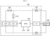
- FIG. 2 is a diagram schematically showing an exemplary configuration of a battery pack 100 according to an embodiment of the present disclosure.
- the battery pack 100 may include a first battery 110, a second battery 120, a connector unit 130, and a BMS (Battery management system) 140.
- BMS Battery management system
- the battery refers to one physically separable independent cell having a negative electrode terminal and a positive electrode terminal.
- a lithium-ion cell or a lithium polymer cell may be regarded as the battery.
- the battery may refer to a battery module in which a plurality of cells are connected in series and/or in parallel.
- the battery pack 100 may include a first battery 110 and a second battery 120.
- the positive electrode terminal of the first battery 110 and the positive electrode terminal of the second battery 120 may be connected to the positive electrode terminal P+ of the battery pack 100.
- the negative electrode terminal of the first battery 110 and the negative electrode terminal of the second battery 120 may be connected to the negative electrode terminal P- of the battery pack 100.
- the connector unit 130 includes electrode terminals P+, P- and a communication terminal CT, and may be configured to be connected to an external device 200.
- the electrode terminal may include a positive electrode terminal P+ and a negative electrode terminal P- of the battery pack 100.
- the electrode terminal can be connected to the external device 200 to form a power line.
- the communication terminal CT can configure a communication line with the external device 200 connected to the battery pack 100.
- the battery pack 100 may be connected to the external device 200.
- the electrode terminal may be connected to an external electrode terminal provided in the external device 200.
- the communication terminal may be connected to an external communication terminal provided in the external device 200.
- the BMS 140 may be configured to determine whether the connector unit 130 and the external device 200 are connected.
- the BMS 140 may be connected to the communication terminal CT of the connector unit 130. Additionally, the BMS 140 can communicate with the external device 200 through a communication line formed by the connection between the communication terminal CT of the connector unit 130 and the external communication terminal of the external device 200. That is, the BMS 140 can determine whether the connector unit 130 and the external device 200 are connected by communicating with the external device 200 through a communication line.
- the BMS 140 can determine whether the connector unit 130 and the external device 200 are connected.
- the BMS 140 can determine not only whether the connector unit 130 and the external device 200 are connected, but also the type of the external device 200 connected to the connector unit 130.
- the BMS 140 may determine the external device 200 connected to the connector unit 130 as a charger 210 or a load 220.
- the charger 210 is a device that can charge the battery pack 100 by applying a charging current to the battery pack 100.
- the load 220 is a device that can discharge the battery pack 100 by receiving a discharge current from the battery pack 100.
- the BMS 140 may be configured to control the electrical connection relationship between the first battery 110, the second battery 120 and the external device 200 according to the external device 200 connected to the connector unit 130.
- the BMS 140 can control the electrical connection relationship between the first battery 110, the second battery 120 and the external device 200 based on the type of the external device 200.
- the BMS 140 can connect the first battery 110 and the external device 200 and block the connection between the second battery 120 and external device 200.
- the BMS 140 may control the operation state of the first relay 150 to a turn-on state and the operation state of the second relay 160 to a turn-off state.
- the BMS 140 can connect the second battery 120 and the external device 200 and block the connection between the first battery 110 and the external device 200.
- the BMS 140 may control the operation state of the first relay 150 to the turn-off state and the operation state of the second relay 160 to the turn-on state.
- the BMS 140 has an advantage of selectively configuring the electrical connection relationship between the batteries 110, 120 provided in the battery pack 100 and the external device 200 based on whether the external device 200 and the battery pack 100 are connected.
- the battery pack 100 may further include a first relay 150 and a second relay 160.
- the first relay 150 is connected between the first battery 110 and the electrode terminal, and may be configured to electrically connect or disconnect the first battery 110 and the electrode terminal depending on the controlled operation state.
- the operation state of the first relay 150 when the operation state of the first relay 150 is the turn-on state, the first battery 110 and the external device 200 may be electrically connected. Conversely, if the operation state of the first relay 150 is the turn-off state, the electrical connection between the first battery 110 and the external device 200 may be blocked.
- the second relay 160 is connected between the second battery 120 and the electrode terminal, and may be configured to electrically connect or disconnect the second battery 120 and the electrode terminal depending on the controlled operation state.
- the second battery 120 and the external device 200 may be electrically connected. Conversely, if the operation state of the second relay 160 is the turn-off state, the electrical connection between the second battery 120 and the external device 200 may be blocked.
- the BMS 140 may be configured to control the connection relationship between the first battery 110, the second battery 120 and the external device 200 by controlling the operation state of the first relay 150 and the second relay 160.
- the BMS 140 can control the operation state of the first relay 150 and the second relay 160 by considering the type of the external device 200 (e.g., the charger 210 or the load 220) and the voltage of the first battery 110.
- first battery 110 and the second battery 120 may be configured to have different negative electrode active materials.
- the first battery 110 may be a graphite-based battery
- the second battery 120 may be a silicon (Si)-based battery.
- the negative electrode active material of the first battery 110 may be 100% graphite, a mixture of graphite and silicon compounds (e.g., SiO and/or SiC), or a mixture of graphite and silicon.
- the negative electrode active material of the second battery 120 may be 100% silicon, a mixture of silicon and a silicon compounds (e.g., SiO and/or SiC), or a mixture of silicon and graphite.
- the negative electrode active materials of the first battery 110 and the second battery 120 are both a mixture of graphite and silicon
- the specific gravities of graphite in the negative electrode active material of the first battery 110 and the negative electrode active material of the second battery 120 may be significantly different.
- the negative electrode active material of the first battery 110 may be a mixture of a large amount of graphite and a small amount of silicon.
- the negative electrode active material of the second battery 120 may be a mixture of a large amount of silicon and a small amount of graphite.
- the silicon-based battery has an advantage that the possibility of lithium plating is significantly lower than the graphite-based battery even when a charging current of 4C or more for fast charging is applied. This is because the silicon-based battery has high energy density and is non-directional, so even when fast charging is performed, the possibility of lithium plating is significantly lower than that of the graphite-based battery.
- silicon-based batteries are not used alone. For example, when both a graphite-based battery and a silicon-based battery charge and discharge at a slow rate, degradation of the graphite-based battery occurs more slowly than that of the silicon-based battery. This is because silicon-based batteries are more resistant to fast charging than graphite-based batteries, but their lifespan characteristics during charging and discharging are not good.
- the battery pack 100 has an advantage of improving fast charging performance and lifespan of the battery pack 100 by including the graphite-based first battery 110 and the silicon-based second battery 120.
- the BMS 140 may optionally include processors, application-specific integrated circuits (ASICs), other chipsets, logic circuits, registers, communication modems, data processing devices, etc. known in the art to execute various control logics performed in the present disclosure.
- ASICs application-specific integrated circuits
- the BMS 140 may be implemented as a set of program modules.
- the program module may be stored in the memory and executed by the BMS 140.
- the memory may be inside or outside the BMS 140 and may be connected to the BMS 140 by various well-known means.
- the memory is not particularly limited in its kind as long as it is a known information storage means that can record, erase, update and read data.
- the information storage means may include RAM, flash memory, ROM, EEPROM, registers, and the like.
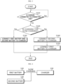
- FIG. 3 is a diagram schematically showing the charging process of the battery pack 100 according to an embodiment of the present disclosure.
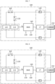
- FIGS. 4 and 5 are diagrams schematically showing an embodiment in which the battery pack 100 according to an embodiment of the present disclosure is slowly charged.
- FIGS. 6 to 8 are diagrams schematically showing an embodiment in which the battery pack 100 according to an embodiment of the present disclosure is fast charged.
- Step S310 is a step of determining whether the connector unit 130 and the charger 210 are connected, and may be performed by the BMS 140. In step S310, if the charger 210 is connected to the connector unit 130, step S320 may be performed, and if the charger 210 is not connected to the connector unit 130, step S310 may be performed again.
- the BMS 140 can determine whether the connector unit 130 and the charger 210 serving as the external device 200 are connected. Additionally, when the charger 210 is connected to the connector unit 130 as the external device 200, the BMS 140 may be configured to receive information about the charging type from the charger 210.
- the charging type may be slow charging or fast charging.
- Slow charging and fast charging can be distinguished according to the preset C-RATE.
- the charging C-RATE may be set to target a charging time of about 4 to 5 hours, and for fast charging, the charging C-RATE may be set to target a charging time of about 15 to 30 minutes.
- Step S320 is a step of determining the charging type of the charger 210 connected to the connector unit 130, and can be performed by the BMS 140.
- step S330 may be performed if the charging type is slow charging
- step S340 may be performed if the charging type is fast charging.
- the BMS 140 may be configured to connect at least one of the first battery 110 and the second battery 120 to the charger 210 depending on the charging type.
- Step S330 is a step of connecting the first battery 110 and the second battery 120 to the charger 210 when the charging type is slow charging, and can be performed by the BMS 140.
- the BMS 140 can select the first battery 110 and the second battery 120 as charging target batteries. Additionally, the BMS 140 can control the operation state of the first relay 150 to the turn-on state in order to connect the first battery 110 to the charger 210. Additionally, the BMS 140 can control the operation state of the second relay 160 to the turn-on state in order to connect the second battery 120 and the charger 210.
- the BMS 140 can be configured to connect the second battery 120 and the charger 210 and block the connection between the first battery 110 and the charger 210.
- the charger 210 and the second battery 120 can be connected.
- the connection between the first battery 110 and the charger 210 is blocked.
- the BMS 140 can select the second battery 120 as the charging target battery. Additionally, the BMS 140 can control the operation state of the second relay 160 to the turn-on state in order to connect the second battery 120 to the charger 210. Additionally, the BMS 140 can control the operation state of the first relay 150 to the turn-off state to block the connection between the first battery 110 and the charger 210.
- Step S350 is a step of connecting the first battery 110 and the charger 210, and can be performed by the BMS 140.
- the BMS 140 can be configured to change the charging type to slow charging after fast charging of the second battery 120 ends.
- the BMS 140 can request a change in charging type to the charger 210 through the communication terminal CT.
- the BMS 140 can connect the first battery 110 and the charger 210.
- the BMS 140 can block the connection between the second battery 120 and the charger 210.
- the second battery 120 for which fast charging has been completed may be disconnected from the charger 210, and the first battery 110 requiring slow charging may be connected to the charger 210. That is, the BMS 140 can control the operation state of the second relay 160 to the turn-off state and the operation state of the first relay 150 to the turn-on state.
- the battery pack 100 may rapidly charge the second battery 120 that is resistant to fast charging (less likely to degrade due to fast charging), and slowly charge the first battery 110 that is vulnerable to fast charging (more likely to degrade due to fast charging).
- both the first battery 110 and the second battery 120 which have different characteristics, can be quickly charged.
- degradation of the first battery 110 can be prevented during the charging process, there is an advantage in that the lifespan of the first battery 110 is increased as a result.
- FIGS. 9 to 11 are diagrams schematically showing an embodiment in which the battery pack 100 according to an embodiment of the present disclosure is discharged. Specifically, FIG. 9 is a diagram schematically showing the discharging process of the battery pack 100. FIGS. 10 and 11 are diagrams schematically showing an exemplary configuration of the battery pack 100 during a discharging process.
- Step S810 is a step of determining whether the connector unit 130 and the load 220 are connected, and may be performed by the BMS 140. In step S810, if the load 220 is connected to the connector unit 130, step S820 may be performed, and if the load 220 is not connected to the connector unit 130, step S810 may be performed again.
- the BMS 140 may be connected to the load 220 through the communication terminal CT.
- the BMS 140 can determine whether the connector unit 130 and the load 220 are connected by communicating with the load 220.
- Step S820 is a step of connecting the first battery 110 and the load 220 when the load 220 is connected to the connector unit 130, and can be performed by the BMS 140.
- the BMS 140 may be configured to connect the first battery 110 and the load 220 and block the connection between the second battery 120 and the load 220.
- the BMS 140 may control the operation state of the first relay 150 to the turn-on state in order to connect the first battery 110 to the load 220. Additionally, the BMS 140 can control the operation state of the second relay 160 to the turn-off state in order to block the connection between the second battery 120 and the load 220.
- Step S830 is a step of measuring the voltage of the first battery 110, and can be performed by the BMS 140.
- the BMS 140 may be configured to measure the voltage of the first battery 110. Additionally, the BMS 140 may be configured to control the connection between the first battery 110, the second battery 120 and the load 220 based on the voltage of the first battery 110.
- the BMS 140 can be connected to the first battery 110 and the second battery 120 through the sensing line SL. Additionally, the BMS 140 can measure the current, voltage, and temperature of the first battery 110 and the second battery 120 through the sensing line SL. In FIG. 10 , the BMS 140 and the sensing line SL are briefly shown, but the measurement unit included in the BMS 140 (e.g., including a voltage sensor, a current sensor, and a temperature sensor) may measure is used to measure a current, voltage, and temperature of the first battery 110 and the second battery 120 through the sensing line SL.
- the measurement unit included in the BMS 140 e.g., including a voltage sensor, a current sensor, and a temperature sensor
- Step S840 is a step of comparing the voltage of the first battery 110 and the threshold voltage, and may be performed by the BMS 140. In step S840, if the voltage of the first battery 110 is less than the threshold voltage, step S850 may be performed, and if the voltage of the first battery 110 is equal to or more than the threshold voltage, step S830 may be performed again.
- the threshold voltage may be preset to a voltage required to charge the first battery 110.
- the threshold voltage can be set in advance to a voltage at which it is considered that charging is required in order to prevent the first battery 110 from rapidly degrading.
- This threshold voltage is set to correspond to the type of the first battery 110 and can be set theoretically or experimentally.
- Step S850 is a step of connecting the second battery 120 and the load 220, and can be performed by the BMS 140.
- the BMS 140 may be configured to connect the second battery 120 and the load 220 when the voltage of the first battery 110 is less than a preset threshold voltage.
- the BMS 140 may be configured to block the connection between the first battery 110 and the load 220 to prevent the first battery 110 from being further discharged.
- the BMS 140 can connect the load 220 and the second battery 120 by controlling the operation state of the second relay 160 to the turn-on state.
- the BMS 140 can block the connection between the load 220 and the first battery 110 by controlling the operation state of the first relay 150 to the turn-off state. In this case, since the first battery 110 is no longer discharged, degradation of the first battery 110 can be prevented.
- the battery pack 100 can prevent the first battery 110 from degrading due to discharge by controlling the electrical connection between the first battery 110, the second battery 120 and the load 220 according to the voltage of the first battery 110. Accordingly, the lifespan of the first battery 110 can be increased.
- FIGS. 12 and 13 are diagrams schematically showing another embodiment in which the battery pack according to an embodiment of the present disclosure is discharged.
- FIG. 12 is a diagram schematically showing the discharging process of the battery pack 100.
- FIG. 13 is a diagram schematically showing an exemplary configuration of the battery pack 100 during a discharge process.
- steps S860 to S880 of FIG. 12 may be performed after step S850 of FIG. 9 .
- Step S860 may be performed after step S850 of FIG. 9 .
- Step S860 is a step of measuring the voltage of the second battery 120, and can be performed by the BMS 140.
- the BMS 140 can measure the voltage, current, and temperature of the second battery 120 through the sensing line SL.
- Step S870 is a step of comparing the voltage of the first battery 110 and the voltage of the second battery 120, and may be performed by the BMS 140. If the voltage of the first battery 110 and the voltage of the second battery 120 are the same in step S870, step S880 may be performed, otherwise, step S860 may be performed.
- Step S880 is a step of connecting the first battery 110 and the load 220, and can be performed by the BMS 140.
- the BMS 140 may be configured to connect the first battery 110 to the load 220 again when the voltages of the first battery 110 and the second battery 120 are the same. That is, if both the voltage of the first battery 110 and the voltage of the second battery 120 correspond to the threshold voltage, both the first battery 110 and the second battery 120 can be connected to the load 220.
- the BMS 140 can connect the first battery 110 and the load 220 by controlling the operation state of the first relay 150 to the turn-on state. That is, since both the operation states of the first relay 150 and the second relay 160 are turn-on state, the first battery 110 and the second battery 120 can be connected to the load 220 in a parallel structure.
- the BMS 140 Even if the voltage of the first battery 110 and the voltage of the second battery 120 are different, if the BMS 140 controls the operation state of both the first relay 150 and the second relay 160 to the turn-on state, accidents such as heat generation, fire, or explosion may occur due to the difference in rated capacity of the first battery 110 and the second battery 120. Therefore, in order to prevent degradation of the first battery 110, the BMS 140 first blocks the connection between the first battery 110 and the load 220, and then when the voltage of the second battery 120 becomes the same as the voltage of the first battery 110, the BMS may connect the first battery 110 and the load 220 again. Because both the first battery 110 and the second battery 120 are connected to the load 220, power can be smoothly supplied to the load 220.
- FIG. 14 is a diagram schematically showing the appearance of a vehicle according to another embodiment of the present disclosure.
- the battery pack 100 may be included in a vehicle 10 such as an electric vehicle (EV) or a hybrid vehicle (HV).
- the battery pack 100 may drive the vehicle 10 by supplying power to a motor through an inverter included in the vehicle 10.
Landscapes
- Engineering & Computer Science (AREA)
- Manufacturing & Machinery (AREA)
- Chemical & Material Sciences (AREA)
- Chemical Kinetics & Catalysis (AREA)
- Electrochemistry (AREA)
- General Chemical & Material Sciences (AREA)
- Power Engineering (AREA)
- Microelectronics & Electronic Packaging (AREA)
- Charge And Discharge Circuits For Batteries Or The Like (AREA)
- Secondary Cells (AREA)
- Battery Mounting, Suspending (AREA)
- Life Sciences & Earth Sciences (AREA)
- Sustainable Development (AREA)
- Sustainable Energy (AREA)
- Transportation (AREA)
- Mechanical Engineering (AREA)
Abstract
Description
- The present application claims priority to
Korean Patent Application No. 10-2022-0065676 filed on May 27, 2022 - The present disclosure relates to a battery pack, and more specifically, to a battery pack with improved fast charging function.
- Recently, the demand for portable electronic products such as notebook computers, video cameras and portable telephones has increased sharply, and electric vehicles, energy storage batteries, robots, satellites and the like have been developed in earnest. Accordingly, high-performance batteries allowing repeated charging and discharging are being actively studied.
- Batteries commercially available at present include nickel-cadmium batteries, nickel hydrogen batteries, nickel-zinc batteries, lithium batteries and the like. Among them, the lithium batteries are in the limelight since they have almost no memory effect compared to nickel-based batteries and also have very low self-charging rate and high energy density.
- Recently, as the number of users of electric vehicles increases, the demand for fast charging for batteries included in electric vehicles is increasing. For example, to achieve fast charging within 15 minutes, a current of 4C (C-rate) or more must be applied. However, since batteries for electric vehicles in mass production are graphite-based batteries, there is a problem that lithium plating may occur when a high current of 4C (C-rate) or more is applied.
- Here, lithium plating (Li-plating) is a phenomenon in which lithium metal is deposited on the surface of the negative electrode. Lithium plating causes side reactions with electrolyte and/or changes in the kinetic balance of the battery, causing battery degradation. In addition, as lithium metal is deposited on the surface of the negative electrode, an internal short circuit of the battery may occur, and there is a risk of ignition or explosion due to an internal short circuit.
- Therefore, it is necessary to develop a battery pack that prevents lithium plating and allows fast charging.
- The present disclosure is designed to solve the problems of the related art, and therefore the present disclosure is directed to providing a battery pack with improved fast charging function.
- These and other objects and advantages of the present disclosure may be understood from the following detailed description and will become more fully apparent from the exemplary embodiments of the present disclosure. Also, it will be easily understood that the objects and advantages of the present disclosure may be realized by the means shown in the appended claims and combinations thereof.
- A battery pack according to one aspect of the present disclosure may comprise a first battery and a second battery; a connector unit having an electrode terminal and a communication terminal and configured to be connected to an external device; and a BMS configured to determine whether the connector unit and the external device are connected and control the electrical connection relationship between the first battery, the second battery and the external device according to the external device connected to the connector unit.
- When a charger is connected to the connector unit as the external device, the BMS may be configured to receive information about a charging type from the charger and connect at least one of the first battery and the second battery to the charger according to the charging type.
- The BMS may be configured to connect the first battery and the second battery to the charger when the charging type is slow charging.
- The BMS may be configured to connect the second battery to the charger and block the connection between the first battery and the charger when the charging type is fast charging.
- The BMS may be configured to change the charging type to slow charging after fast charging of the second battery ends and connect the first battery and the charger.
- When a load is connected to the connector unit as the external device, the BMS may be configured to connect the first battery and the load and block the connection between the second battery and the load.
- The BMS may be configured to measure a voltage of the first battery connected to the load and control the connection between the first battery, the second battery and the load based on the voltage of the first battery.
- The BMS may be configured to connect the second battery and the load and block the connection between the first battery and the load when the voltage of the first battery is less than a preset threshold voltage.
- The BMS may be configured to measure a voltage of the second battery and, when the voltages of the first battery and the second battery are the same, connect the first battery to the load again.
- A battery pack according to another aspect of the present disclosure may further comprise a first relay connected between the first battery and the electrode terminal and configured to electrically connect or disconnect the first battery and the electrode terminal depending on a controlled operation state; and a second relay connected between the second battery and the electrode terminal and configured to electrically connect or disconnect the second battery and the electrode terminal depending on the controlled operation state.
- The BMS may be configured to control the connection relationship between the first battery, the second battery and the external device by controlling the operation states of the first relay and the second relay.
- The first battery and the second battery may be configured to have different negative electrode active materials.
- A vehicle battery pack according to still another aspect of the present disclosure may comprise the battery pack according to an aspect of the present disclosure.
- According to one aspect of the present disclosure, there is an advantage in providing a battery pack that prevents lithium plating and enables fast charging.
- The effects of the present disclosure are not limited to the effects mentioned above, and other effects not mentioned will be clearly understood by those skilled in the art from the description of the claims.
- The accompanying drawings illustrate a preferred embodiment of the present disclosure and together with the foregoing disclosure, serve to provide further understanding of the technical features of the present disclosure, and thus, the present disclosure is not construed as being limited to the drawing.
-
FIG. 1 is a diagram schematically showing a battery pack according to an embodiment of the present disclosure. -
FIG. 2 is a diagram schematically showing an exemplary configuration of a battery pack according to an embodiment of the present disclosure. -
FIG. 3 is a diagram schematically showing the charging process of the battery pack according to an embodiment of the present disclosure. -
FIGS. 4 and5 are diagrams schematically showing an embodiment in which the battery pack according to an embodiment of the present disclosure is slowly charged. -
FIGS. 6 to 8 are diagrams schematically showing an embodiment in which the battery pack according to an embodiment of the present disclosure is fast charged. -
FIGS. 9 to 11 are diagrams schematically showing an embodiment in which the battery pack according to an embodiment of the present disclosure is discharged. -
FIGS. 12 and 13 are diagrams schematically showing another embodiment in which the battery pack according to an embodiment of the present disclosure is discharged. -
FIG. 14 is a diagram schematically showing the appearance of a vehicle according to another embodiment of the present disclosure. - It should be understood that the terms used in the specification and the appended claims should not be construed as limited to general and dictionary meanings, but interpreted based on the meanings and concepts corresponding to technical aspects of the present disclosure on the basis of the principle that the inventor is allowed to define terms appropriately for the best explanation.
- Therefore, the description proposed herein is just a preferable example for the purpose of illustrations only, not intended to limit the scope of the disclosure, so it should be understood that other equivalents and modifications could be made thereto without departing from the scope of the disclosure.
- Additionally, in describing the present disclosure, when it is deemed that a detailed description of relevant known elements or functions renders the key subject matter of the present disclosure ambiguous, the detailed description is omitted herein.
- The terms including the ordinal number such as "first", "second" and the like, may be used to distinguish one element from another among various elements, but not intended to limit the elements by the terms.
- Throughout the specification, when a portion is referred to as "comprising" or "including" any element, it means that the portion may include other elements further, without excluding other elements, unless specifically stated otherwise.
- In addition, throughout the specification, when a portion is referred to as being "connected" to another portion, it is not limited to the case that they are "directly connected", but it also includes the case where they are "indirectly connected" with another element being interposed between them.
- Hereinafter, a preferred embodiment of the present disclosure will be described in detail with reference to the accompanying drawings.
-
FIG. 1 is a diagram schematically showing abattery pack 100 according to an embodiment of the present disclosure.FIG. 2 is a diagram schematically showing an exemplary configuration of abattery pack 100 according to an embodiment of the present disclosure. - Referring to
FIG. 1 , thebattery pack 100 may include afirst battery 110, asecond battery 120, aconnector unit 130, and a BMS (Battery management system) 140. - Here, the battery refers to one physically separable independent cell having a negative electrode terminal and a positive electrode terminal. For example, a lithium-ion cell or a lithium polymer cell may be regarded as the battery. In addition, the battery may refer to a battery module in which a plurality of cells are connected in series and/or in parallel.
- In the embodiment of
FIG. 2 , thebattery pack 100 may include afirst battery 110 and asecond battery 120. The positive electrode terminal of thefirst battery 110 and the positive electrode terminal of thesecond battery 120 may be connected to the positive electrode terminal P+ of thebattery pack 100. Also, the negative electrode terminal of thefirst battery 110 and the negative electrode terminal of thesecond battery 120 may be connected to the negative electrode terminal P- of thebattery pack 100. - The
connector unit 130 includes electrode terminals P+, P- and a communication terminal CT, and may be configured to be connected to anexternal device 200. - For example, the electrode terminal may include a positive electrode terminal P+ and a negative electrode terminal P- of the
battery pack 100. The electrode terminal can be connected to theexternal device 200 to form a power line. Also, the communication terminal CT can configure a communication line with theexternal device 200 connected to thebattery pack 100. - In the embodiment of
FIG. 2 , thebattery pack 100 may be connected to theexternal device 200. In this case, the electrode terminal may be connected to an external electrode terminal provided in theexternal device 200. Additionally, the communication terminal may be connected to an external communication terminal provided in theexternal device 200. - The
BMS 140 may be configured to determine whether theconnector unit 130 and theexternal device 200 are connected. - For example, the
BMS 140 may be connected to the communication terminal CT of theconnector unit 130. Additionally, theBMS 140 can communicate with theexternal device 200 through a communication line formed by the connection between the communication terminal CT of theconnector unit 130 and the external communication terminal of theexternal device 200. That is, theBMS 140 can determine whether theconnector unit 130 and theexternal device 200 are connected by communicating with theexternal device 200 through a communication line. - As another example, based on a change in at least one of the voltage, current, and resistance of the power line formed by the connection between the electrode terminal of the
connector unit 130 and the external electrode terminal of theexternal device 200, theBMS 140 can determine whether theconnector unit 130 and theexternal device 200 are connected. - Preferably, the
BMS 140 can determine not only whether theconnector unit 130 and theexternal device 200 are connected, but also the type of theexternal device 200 connected to theconnector unit 130. For example, theBMS 140 may determine theexternal device 200 connected to theconnector unit 130 as acharger 210 or aload 220. Here, thecharger 210 is a device that can charge thebattery pack 100 by applying a charging current to thebattery pack 100. Also, theload 220 is a device that can discharge thebattery pack 100 by receiving a discharge current from thebattery pack 100. - The
BMS 140 may be configured to control the electrical connection relationship between thefirst battery 110, thesecond battery 120 and theexternal device 200 according to theexternal device 200 connected to theconnector unit 130. - Specifically, when the
external device 200 is connected to theconnector unit 130, theBMS 140 can control the electrical connection relationship between thefirst battery 110, thesecond battery 120 and theexternal device 200 based on the type of theexternal device 200. - For example, the
BMS 140 can connect thefirst battery 110 and theexternal device 200 and block the connection between thesecond battery 120 andexternal device 200. In the embodiment ofFIG. 2 , theBMS 140 may control the operation state of thefirst relay 150 to a turn-on state and the operation state of thesecond relay 160 to a turn-off state. - As another example, the
BMS 140 can connect thesecond battery 120 and theexternal device 200 and block the connection between thefirst battery 110 and theexternal device 200. In the embodiment ofFIG. 2 , theBMS 140 may control the operation state of thefirst relay 150 to the turn-off state and the operation state of thesecond relay 160 to the turn-on state. - In other words, the
BMS 140 has an advantage of selectively configuring the electrical connection relationship between thebatteries battery pack 100 and theexternal device 200 based on whether theexternal device 200 and thebattery pack 100 are connected. - Referring further to
FIG. 1 , thebattery pack 100 may further include afirst relay 150 and asecond relay 160. - The
first relay 150 is connected between thefirst battery 110 and the electrode terminal, and may be configured to electrically connect or disconnect thefirst battery 110 and the electrode terminal depending on the controlled operation state. - In the embodiment of
FIG. 2 , when the operation state of thefirst relay 150 is the turn-on state, thefirst battery 110 and theexternal device 200 may be electrically connected. Conversely, if the operation state of thefirst relay 150 is the turn-off state, the electrical connection between thefirst battery 110 and theexternal device 200 may be blocked. - The
second relay 160 is connected between thesecond battery 120 and the electrode terminal, and may be configured to electrically connect or disconnect thesecond battery 120 and the electrode terminal depending on the controlled operation state. - In the embodiment of
FIG. 2 , when the operation state of thesecond relay 160 is the turn-on state, thesecond battery 120 and theexternal device 200 may be electrically connected. Conversely, if the operation state of thesecond relay 160 is the turn-off state, the electrical connection between thesecond battery 120 and theexternal device 200 may be blocked. - Additionally, the
BMS 140 may be configured to control the connection relationship between thefirst battery 110, thesecond battery 120 and theexternal device 200 by controlling the operation state of thefirst relay 150 and thesecond relay 160. - Specifically, the
BMS 140 can control the operation state of thefirst relay 150 and thesecond relay 160 by considering the type of the external device 200 (e.g., thecharger 210 or the load 220) and the voltage of thefirst battery 110. - Meanwhile, the
first battery 110 and thesecond battery 120 may be configured to have different negative electrode active materials. - Specifically, the
first battery 110 may be a graphite-based battery, and thesecond battery 120 may be a silicon (Si)-based battery. - For example, the negative electrode active material of the
first battery 110 may be 100% graphite, a mixture of graphite and silicon compounds (e.g., SiO and/or SiC), or a mixture of graphite and silicon. - For example, the negative electrode active material of the
second battery 120 may be 100% silicon, a mixture of silicon and a silicon compounds (e.g., SiO and/or SiC), or a mixture of silicon and graphite. - Here, when the negative electrode active materials of the
first battery 110 and thesecond battery 120 are both a mixture of graphite and silicon, the specific gravities of graphite in the negative electrode active material of thefirst battery 110 and the negative electrode active material of thesecond battery 120 may be significantly different. In other words, the negative electrode active material of thefirst battery 110 may be a mixture of a large amount of graphite and a small amount of silicon. Conversely, the negative electrode active material of thesecond battery 120 may be a mixture of a large amount of silicon and a small amount of graphite. - In general, when a charging current of 4C or more for fast charging is applied to a graphite-based battery, there is a problem that the possibility of lithium plating significantly increases. On the other hand, the silicon-based battery has an advantage that the possibility of lithium plating is significantly lower than the graphite-based battery even when a charging current of 4C or more for fast charging is applied. This is because the silicon-based battery has high energy density and is non-directional, so even when fast charging is performed, the possibility of lithium plating is significantly lower than that of the graphite-based battery.
- On the other hand, because the lifespan characteristics of graphite-based batteries are much better than those of silicon-based batteries, silicon-based batteries are not used alone. For example, when both a graphite-based battery and a silicon-based battery charge and discharge at a slow rate, degradation of the graphite-based battery occurs more slowly than that of the silicon-based battery. This is because silicon-based batteries are more resistant to fast charging than graphite-based batteries, but their lifespan characteristics during charging and discharging are not good.
- Therefore, the
battery pack 100 according to an embodiment of the present disclosure has an advantage of improving fast charging performance and lifespan of thebattery pack 100 by including the graphite-basedfirst battery 110 and the silicon-basedsecond battery 120. - Meanwhile, the
BMS 140 may optionally include processors, application-specific integrated circuits (ASICs), other chipsets, logic circuits, registers, communication modems, data processing devices, etc. known in the art to execute various control logics performed in the present disclosure. Also, when the control logic is implemented as software, theBMS 140 may be implemented as a set of program modules. At this time, the program module may be stored in the memory and executed by theBMS 140. The memory may be inside or outside theBMS 140 and may be connected to theBMS 140 by various well-known means. - For example, the memory is not particularly limited in its kind as long as it is a known information storage means that can record, erase, update and read data. As an example, the information storage means may include RAM, flash memory, ROM, EEPROM, registers, and the like.
-
FIG. 3 is a diagram schematically showing the charging process of thebattery pack 100 according to an embodiment of the present disclosure.FIGS. 4 and5 are diagrams schematically showing an embodiment in which thebattery pack 100 according to an embodiment of the present disclosure is slowly charged.FIGS. 6 to 8 are diagrams schematically showing an embodiment in which thebattery pack 100 according to an embodiment of the present disclosure is fast charged. - Step S310 is a step of determining whether the
connector unit 130 and thecharger 210 are connected, and may be performed by theBMS 140. In step S310, if thecharger 210 is connected to theconnector unit 130, step S320 may be performed, and if thecharger 210 is not connected to theconnector unit 130, step S310 may be performed again. - The
BMS 140 can determine whether theconnector unit 130 and thecharger 210 serving as theexternal device 200 are connected. Additionally, when thecharger 210 is connected to theconnector unit 130 as theexternal device 200, theBMS 140 may be configured to receive information about the charging type from thecharger 210. - Here, the charging type may be slow charging or fast charging. Slow charging and fast charging can be distinguished according to the preset C-RATE. For example, for slow charging, the charging C-RATE may be set to target a charging time of about 4 to 5 hours, and for fast charging, the charging C-RATE may be set to target a charging time of about 15 to 30 minutes.
- Specifically, when the
charger 210 is connected to theconnector unit 130, theBMS 140 and thecharger 210 can communicate through the communication terminal CT of theconnector unit 130. For example, theBMS 140 and thecharger 210 can communicate using PLC (power line communication) technology. TheBMS 140 can receive information about the charging type from thecharger 210. - Step S320 is a step of determining the charging type of the
charger 210 connected to theconnector unit 130, and can be performed by theBMS 140. In step S320, step S330 may be performed if the charging type is slow charging, and step S340 may be performed if the charging type is fast charging. - Referring to steps S330 and S340, the
BMS 140 may be configured to connect at least one of thefirst battery 110 and thesecond battery 120 to thecharger 210 depending on the charging type. - Specifically, the
BMS 140 can be configured to select the first andsecond batteries second battery 120 as the charging target battery depending on the charging type. Additionally, theBMS 140 can be configured to connect the charging target battery and thecharger 210, and to block the connection between the remaining unselected batteries and thecharger 210. - Step S330 is a step of connecting the
first battery 110 and thesecond battery 120 to thecharger 210 when the charging type is slow charging, and can be performed by theBMS 140. - Specifically, when the charging type is slow charging, the
BMS 140 can be configured to connect both thefirst battery 110 and thesecond battery 120 to thecharger 210. That is, if the charging type is slow charging, both thefirst battery 110 and thesecond battery 120 can be selected as the charging target battery. - For example, in the embodiment of
FIG. 4 , if the charging type of thecharger 210 is slow charging, thecharger 210 may be connected to thefirst battery 110 and thesecond battery 120. - For example, in the embodiment of
FIG. 5 , if the charging type of thecharger 210 is slow charging, theBMS 140 can select thefirst battery 110 and thesecond battery 120 as charging target batteries. Additionally, theBMS 140 can control the operation state of thefirst relay 150 to the turn-on state in order to connect thefirst battery 110 to thecharger 210. Additionally, theBMS 140 can control the operation state of thesecond relay 160 to the turn-on state in order to connect thesecond battery 120 and thecharger 210. - In other words, if the charging type is slow charging, there is no risk of degradation of the
first battery 110 and thesecond battery 120 due to charging, soBMS 140 can control the operation state of both thefirst relay 150 and thesecond relay 160 to the turn-on state. Accordingly, thefirst battery 110 and thesecond battery 120 can be charged together by thecharger 210. - Step S340 is a step of connecting the
second battery 120 and thecharger 210 when the charging type is fast charging, and can be performed by theBMS 140. Also, theBMS 140 can block the connection between thefirst battery 110 and thecharger 210. - Specifically, when the charging type is fast charging, the
BMS 140 can be configured to connect thesecond battery 120 and thecharger 210 and block the connection between thefirst battery 110 and thecharger 210. - In the embodiment of
FIG. 6 , if the charging type of thecharger 210 is fast charging, thecharger 210 and thesecond battery 120 can be connected. Here, the connection between thefirst battery 110 and thecharger 210 is blocked. - In the embodiment of
FIG. 7 , if the charging type of thecharger 210 is fast charging, theBMS 140 can select thesecond battery 120 as the charging target battery. Additionally, theBMS 140 can control the operation state of thesecond relay 160 to the turn-on state in order to connect thesecond battery 120 to thecharger 210. Additionally, theBMS 140 can control the operation state of thefirst relay 150 to the turn-off state to block the connection between thefirst battery 110 and thecharger 210. - Step S350 is a step of connecting the
first battery 110 and thecharger 210, and can be performed by theBMS 140. - Specifically, the
BMS 140 can be configured to change the charging type to slow charging after fast charging of thesecond battery 120 ends. For example, theBMS 140 can request a change in charging type to thecharger 210 through the communication terminal CT. - Also, the
BMS 140 can connect thefirst battery 110 and thecharger 210. Here, preferably, theBMS 140 can block the connection between thesecond battery 120 and thecharger 210. - For example, in the embodiment of
FIG. 8 , thesecond battery 120 for which fast charging has been completed may be disconnected from thecharger 210, and thefirst battery 110 requiring slow charging may be connected to thecharger 210. That is, theBMS 140 can control the operation state of thesecond relay 160 to the turn-off state and the operation state of thefirst relay 150 to the turn-on state. - Therefore, according to an embodiment of the present disclosure, the
battery pack 100 may rapidly charge thesecond battery 120 that is resistant to fast charging (less likely to degrade due to fast charging), and slowly charge thefirst battery 110 that is vulnerable to fast charging (more likely to degrade due to fast charging). In other words, through relay control by theBMS 140 included in thebattery pack 100, both thefirst battery 110 and thesecond battery 120, which have different characteristics, can be quickly charged. In addition, since degradation of thefirst battery 110 can be prevented during the charging process, there is an advantage in that the lifespan of thefirst battery 110 is increased as a result. -
FIGS. 9 to 11 are diagrams schematically showing an embodiment in which thebattery pack 100 according to an embodiment of the present disclosure is discharged. Specifically,FIG. 9 is a diagram schematically showing the discharging process of thebattery pack 100.FIGS. 10 and 11 are diagrams schematically showing an exemplary configuration of thebattery pack 100 during a discharging process. - Step S810 is a step of determining whether the
connector unit 130 and theload 220 are connected, and may be performed by theBMS 140. In step S810, if theload 220 is connected to theconnector unit 130, step S820 may be performed, and if theload 220 is not connected to theconnector unit 130, step S810 may be performed again. - For example, in the embodiment of
FIG. 10 , theBMS 140 may be connected to theload 220 through the communication terminal CT. In addition, theBMS 140 can determine whether theconnector unit 130 and theload 220 are connected by communicating with theload 220. - Step S820 is a step of connecting the
first battery 110 and theload 220 when theload 220 is connected to theconnector unit 130, and can be performed by theBMS 140. - Specifically, when the
load 220 is connected to theconnector unit 130 as theexternal device 200, theBMS 140 may be configured to connect thefirst battery 110 and theload 220 and block the connection between thesecond battery 120 and theload 220. - For example, in the embodiment of
FIG. 10 , theBMS 140 may control the operation state of thefirst relay 150 to the turn-on state in order to connect thefirst battery 110 to theload 220. Additionally, theBMS 140 can control the operation state of thesecond relay 160 to the turn-off state in order to block the connection between thesecond battery 120 and theload 220. - Step S830 is a step of measuring the voltage of the
first battery 110, and can be performed by theBMS 140. - Specifically, the
BMS 140 may be configured to measure the voltage of thefirst battery 110. Additionally, theBMS 140 may be configured to control the connection between thefirst battery 110, thesecond battery 120 and theload 220 based on the voltage of thefirst battery 110. - In the embodiment of
FIG. 10 , theBMS 140 can be connected to thefirst battery 110 and thesecond battery 120 through the sensing line SL. Additionally, theBMS 140 can measure the current, voltage, and temperature of thefirst battery 110 and thesecond battery 120 through the sensing line SL. InFIG. 10 , theBMS 140 and the sensing line SL are briefly shown, but the measurement unit included in the BMS 140 (e.g., including a voltage sensor, a current sensor, and a temperature sensor) may measure is used to measure a current, voltage, and temperature of thefirst battery 110 and thesecond battery 120 through the sensing line SL. - Step S840 is a step of comparing the voltage of the
first battery 110 and the threshold voltage, and may be performed by theBMS 140. In step S840, if the voltage of thefirst battery 110 is less than the threshold voltage, step S850 may be performed, and if the voltage of thefirst battery 110 is equal to or more than the threshold voltage, step S830 may be performed again. - Here, the threshold voltage may be preset to a voltage required to charge the
first battery 110. In other words, the threshold voltage can be set in advance to a voltage at which it is considered that charging is required in order to prevent thefirst battery 110 from rapidly degrading. This threshold voltage is set to correspond to the type of thefirst battery 110 and can be set theoretically or experimentally. - Step S850 is a step of connecting the
second battery 120 and theload 220, and can be performed by theBMS 140. - Specifically, the
BMS 140 may be configured to connect thesecond battery 120 and theload 220 when the voltage of thefirst battery 110 is less than a preset threshold voltage. Preferably, theBMS 140 may be configured to block the connection between thefirst battery 110 and theload 220 to prevent thefirst battery 110 from being further discharged. - For example, in the embodiment of
FIG. 11 , theBMS 140 can connect theload 220 and thesecond battery 120 by controlling the operation state of thesecond relay 160 to the turn-on state. In addition, theBMS 140 can block the connection between theload 220 and thefirst battery 110 by controlling the operation state of thefirst relay 150 to the turn-off state. In this case, since thefirst battery 110 is no longer discharged, degradation of thefirst battery 110 can be prevented. - In other words, the
battery pack 100 according to an embodiment of the present disclosure can prevent thefirst battery 110 from degrading due to discharge by controlling the electrical connection between thefirst battery 110, thesecond battery 120 and theload 220 according to the voltage of thefirst battery 110. Accordingly, the lifespan of thefirst battery 110 can be increased. -
FIGS. 12 and 13 are diagrams schematically showing another embodiment in which the battery pack according to an embodiment of the present disclosure is discharged. Specifically,FIG. 12 is a diagram schematically showing the discharging process of thebattery pack 100.FIG. 13 is a diagram schematically showing an exemplary configuration of thebattery pack 100 during a discharge process. Here, steps S860 to S880 ofFIG. 12 may be performed after step S850 ofFIG. 9 . - Step S860 may be performed after step S850 of
FIG. 9 . Step S860 is a step of measuring the voltage of thesecond battery 120, and can be performed by theBMS 140. - For example, in
FIG. 13 , theBMS 140 can measure the voltage, current, and temperature of thesecond battery 120 through the sensing line SL. - Step S870 is a step of comparing the voltage of the
first battery 110 and the voltage of thesecond battery 120, and may be performed by theBMS 140. If the voltage of thefirst battery 110 and the voltage of thesecond battery 120 are the same in step S870, step S880 may be performed, otherwise, step S860 may be performed. - Step S880 is a step of connecting the
first battery 110 and theload 220, and can be performed by theBMS 140. - Specifically, the
BMS 140 may be configured to connect thefirst battery 110 to theload 220 again when the voltages of thefirst battery 110 and thesecond battery 120 are the same. That is, if both the voltage of thefirst battery 110 and the voltage of thesecond battery 120 correspond to the threshold voltage, both thefirst battery 110 and thesecond battery 120 can be connected to theload 220. - For example, in the embodiment of
FIG. 13 , theBMS 140 can connect thefirst battery 110 and theload 220 by controlling the operation state of thefirst relay 150 to the turn-on state. That is, since both the operation states of thefirst relay 150 and thesecond relay 160 are turn-on state, thefirst battery 110 and thesecond battery 120 can be connected to theload 220 in a parallel structure. - Even if the voltage of the
first battery 110 and the voltage of thesecond battery 120 are different, if theBMS 140 controls the operation state of both thefirst relay 150 and thesecond relay 160 to the turn-on state, accidents such as heat generation, fire, or explosion may occur due to the difference in rated capacity of thefirst battery 110 and thesecond battery 120. Therefore, in order to prevent degradation of thefirst battery 110, theBMS 140 first blocks the connection between thefirst battery 110 and theload 220, and then when the voltage of thesecond battery 120 becomes the same as the voltage of thefirst battery 110, the BMS may connect thefirst battery 110 and theload 220 again. Because both thefirst battery 110 and thesecond battery 120 are connected to theload 220, power can be smoothly supplied to theload 220. -
FIG. 14 is a diagram schematically showing the appearance of a vehicle according to another embodiment of the present disclosure. - Referring to
FIG. 14 , thebattery pack 100 according to an embodiment of the present disclosure may be included in avehicle 10 such as an electric vehicle (EV) or a hybrid vehicle (HV). In addition, thebattery pack 100 may drive thevehicle 10 by supplying power to a motor through an inverter included in thevehicle 10. - The present disclosure has been described in detail. However, it should be understood that the detailed description and specific examples, while indicating preferred embodiments of the disclosure, are given by way of illustration only, since various changes and modifications within the scope of the disclosure will become apparent to those skilled in the art from this detailed description.
- Additionally, many substitutions, modifications and changes may be made to the present disclosure described hereinabove by those skilled in the art without departing from the technical aspects of the present disclosure, and the present disclosure is not limited to the above-described embodiments and the accompanying drawings, and each embodiment may be selectively combined in part or in whole to allow various modifications.
-
- 10: vehicle
- 100: battery pack
- 110: first battery
- 120: second battery
- 130: connector unit
- 140: BMS
- 150: first relay
- 160: second relay
- 200: external device
- 210: charger
- 220: load
Claims (13)
- A battery pack, comprising:a first battery and a second battery;a connector unit having an electrode terminal and a communication terminal and configured to be connected to an external device; anda BMS configured to determine whether the connector unit and the external device are connected and control the electrical connection relationship between the first battery, the second battery and the external device according to the external device connected to the connector unit.
- The battery pack according to claim 1,
wherein when a charger is connected to the connector unit as the external device, the BMS is configured to receive information about a charging type from the charger and connect at least one of the first battery and the second battery to the charger according to the charging type. - The battery pack according to claim 2,
wherein the BMS is configured to connect the first battery and the second battery to the charger when the charging type is slow charging. - The battery pack according to claim 2,
wherein the BMS is configured to connect the second battery to the charger and block the connection between the first battery and the charger when the charging type is fast charging. - The battery pack according to claim 4,
wherein the BMS is configured to change the charging type to slow charging after fast charging of the second battery ends and connect the first battery and the charger. - The battery pack according to claim 1,
wherein when a load is connected to the connector unit as the external device, the BMS is configured to connect the first battery and the load and block the connection between the second battery and the load. - The battery pack according to claim 6,
wherein the BMS is configured to measure a voltage of the first battery connected to the load and control the connection between the first battery, the second battery and the load based on the voltage of the first battery. - The battery pack according to claim 7,
wherein the BMS is configured to connect the second battery and the load and block the connection between the first battery and the load when the voltage of the first battery is less than a preset threshold voltage. - The battery pack according to claim 8,
wherein the BMS is configured to measure a voltage of the second battery and, when the voltages of the first battery and the second battery are the same, connect the first battery to the load again. - The battery pack according to claim 1, further comprising:a first relay connected between the first battery and the electrode terminal and configured to electrically connect or disconnect the first battery and the electrode terminal depending on a controlled operation state; anda second relay connected between the second battery and the electrode terminal and configured to electrically connect or disconnect the second battery and the electrode terminal depending on the controlled operation state.
- The battery pack according to claim 10,
wherein the BMS is configured to control the connection relationship between the first battery, the second battery and the external device by controlling the operation states of the first relay and the second relay. - The battery pack according to claim 1,
wherein the first battery and the second battery are configured to have different negative electrode active materials. - A vehicle, comprising the battery pack according to any one of claims 1 to 12.
Applications Claiming Priority (2)
| Application Number | Priority Date | Filing Date | Title |
|---|---|---|---|
| KR1020220065676A KR20230165638A (en) | 2022-05-27 | 2022-05-27 | Battery pack with enhanced quick charging capability |
| PCT/KR2023/007190 WO2023229400A1 (en) | 2022-05-27 | 2023-05-25 | Battery pack having improved quick charge function |
Publications (2)
| Publication Number | Publication Date |
|---|---|
| EP4503251A1 true EP4503251A1 (en) | 2025-02-05 |
| EP4503251A4 EP4503251A4 (en) | 2025-08-06 |
Family
ID=88919779
Family Applications (1)
| Application Number | Title | Priority Date | Filing Date |
|---|---|---|---|
| EP23812174.3A Pending EP4503251A4 (en) | 2022-05-27 | 2023-05-25 | BATTERY PACK WITH IMPROVED FAST CHARGING FUNCTION |
Country Status (5)
| Country | Link |
|---|---|
| EP (1) | EP4503251A4 (en) |
| JP (1) | JP7857435B2 (en) |
| KR (1) | KR20230165638A (en) |
| CN (1) | CN118382952A (en) |
| WO (1) | WO2023229400A1 (en) |
Family Cites Families (12)
| Publication number | Priority date | Publication date | Assignee | Title |
|---|---|---|---|---|
| US5557188A (en) * | 1994-02-01 | 1996-09-17 | Sun Microsystems, Inc. | Smart battery system and interface |
| US8823323B2 (en) * | 2009-04-16 | 2014-09-02 | Valence Technology, Inc. | Batteries, battery systems, battery submodules, battery operational methods, battery system operational methods, battery charging methods, and battery system charging methods |
| US9800051B2 (en) * | 2015-09-03 | 2017-10-24 | Ensync, Inc. | Method and apparatus for controlling energy flow between dissimilar energy storage devices |
| KR101969389B1 (en) * | 2015-11-02 | 2019-08-13 | 주식회사 엘지화학 | METHOD FOR CONTROLLING SERIAL AND PARALLEL OPERATION OF BATTERY PACKk |
| JP6805841B2 (en) | 2016-08-26 | 2020-12-23 | 株式会社豊田自動織機 | Battery pack and discharge plug |
| KR101751236B1 (en) * | 2016-12-13 | 2017-06-27 | 장원석 | Battery charging system for electric vehicle using separated multi-layer and method thereof |
| JP6787208B2 (en) | 2017-03-23 | 2020-11-18 | 株式会社豊田自動織機 | Battery pack charge control device and charge control method |
| JP2019004595A (en) | 2017-06-14 | 2019-01-10 | 本田技研工業株式会社 | Vehicle power supply |
| JP6930306B2 (en) | 2017-09-05 | 2021-09-01 | トヨタ自動車株式会社 | Electric vehicle |
| KR102458525B1 (en) * | 2017-11-06 | 2022-10-26 | 주식회사 엘지에너지솔루션 | Battery Pack with locking recognition function |
| EP3664251B1 (en) * | 2018-12-07 | 2021-03-03 | Yazaki Corporation | Power supply system |
| KR102673038B1 (en) | 2020-11-13 | 2024-06-10 | 한국화학연구원 | Catalyst using metal-organic framework and method for producing same |
-
2022
- 2022-05-27 KR KR1020220065676A patent/KR20230165638A/en active Pending
-
2023
- 2023-05-25 CN CN202380014712.6A patent/CN118382952A/en active Pending
- 2023-05-25 WO PCT/KR2023/007190 patent/WO2023229400A1/en not_active Ceased
- 2023-05-25 EP EP23812174.3A patent/EP4503251A4/en active Pending
- 2023-05-25 JP JP2024564749A patent/JP7857435B2/en active Active
Also Published As
| Publication number | Publication date |
|---|---|
| WO2023229400A1 (en) | 2023-11-30 |
| KR20230165638A (en) | 2023-12-05 |
| CN118382952A (en) | 2024-07-23 |
| JP2025517118A (en) | 2025-06-03 |
| EP4503251A4 (en) | 2025-08-06 |
| JP7857435B2 (en) | 2026-05-12 |
Similar Documents
| Publication | Publication Date | Title |
|---|---|---|
| CN110679056B (en) | Battery charge management device and method | |
| EP4148950B1 (en) | Battery management apparatus and method | |
| US12500433B2 (en) | Battery management apparatus and method | |
| EP4148865A1 (en) | Battery management apparatus and method | |
| US12352818B2 (en) | Battery management apparatus and method | |
| EP4145589A1 (en) | Battery classification device and method | |
| EP4032746A1 (en) | Method for battery management and battery system providing same | |
| EP4467999A1 (en) | Apparatus and method for diagnosing battery state | |
| US9798609B2 (en) | Battery management unit for preventing performance of erroneous control algorithm from communication error | |
| EP4131568B1 (en) | Battery management apparatus and method | |
| US20250233446A1 (en) | Apparatus for supplying emergency power | |
| US20260043867A1 (en) | Apparatus and Method for Diagnosing Battery | |
| JP7857435B2 (en) | Battery pack with improved fast charging capabilities | |
| EP4632999A1 (en) | Battery management apparatus and method | |
| CN120883419A (en) | Battery management device and method | |
| EP4729962A1 (en) | Apparatus and method for diagnosing battery | |
| US20260038891A1 (en) | Battery information communication system and method | |
| KR102964534B1 (en) | Apparatus and method for diagnosing battery | |
| US20240275200A1 (en) | Battery Management Apparatus and Method, and Battery Pack Including Battery Management Apparatus | |
| EP4733786A1 (en) | Apparatus and method for diagnosing battery | |
| KR102219920B1 (en) | Battery control device and industrial vehicle including thereof | |
| EP4549974A1 (en) | Battery diagnosis device and method | |
| CN121941932A (en) | Battery management device and method | |
| CN121100287A (en) | Apparatus and method for estimating capacity of battery |
Legal Events
| Date | Code | Title | Description |
|---|---|---|---|
| STAA | Information on the status of an ep patent application or granted ep patent |
Free format text: STATUS: THE INTERNATIONAL PUBLICATION HAS BEEN MADE |
|
| PUAI | Public reference made under article 153(3) epc to a published international application that has entered the european phase |
Free format text: ORIGINAL CODE: 0009012 |
|
| STAA | Information on the status of an ep patent application or granted ep patent |
Free format text: STATUS: REQUEST FOR EXAMINATION WAS MADE |
|
| 17P | Request for examination filed |
Effective date: 20241024 |
|
| AK | Designated contracting states |
Kind code of ref document: A1 Designated state(s): AL AT BE BG CH CY CZ DE DK EE ES FI FR GB GR HR HU IE IS IT LI LT LU LV MC ME MK MT NL NO PL PT RO RS SE SI SK SM TR |
|
| A4 | Supplementary search report drawn up and despatched |
Effective date: 20250707 |
|
| RIC1 | Information provided on ipc code assigned before grant |
Ipc: H01M 10/42 20060101AFI20250701BHEP Ipc: H01M 10/44 20060101ALI20250701BHEP Ipc: H01M 10/052 20100101ALI20250701BHEP Ipc: H02J 7/00 20060101ALI20250701BHEP Ipc: B60L 58/10 20190101ALI20250701BHEP |
|
| DAV | Request for validation of the european patent (deleted) | ||
| DAX | Request for extension of the european patent (deleted) | ||
| REG | Reference to a national code |
Ref country code: DE Ref legal event code: R079 Free format text: PREVIOUS MAIN CLASS: H01M0010420000 Ipc: H01M0010052000 Ref country code: DE Ref legal event code: R079 Ref document number: 602023017877 Country of ref document: DE Free format text: PREVIOUS MAIN CLASS: H01M0010420000 Ipc: H01M0010052000 |
|
| GRAP | Despatch of communication of intention to grant a patent |
Free format text: ORIGINAL CODE: EPIDOSNIGR1 |
|
| STAA | Information on the status of an ep patent application or granted ep patent |
Free format text: STATUS: GRANT OF PATENT IS INTENDED |
|
| RIC1 | Information provided on ipc code assigned before grant |
Ipc: H01M 10/052 20100101AFI20251128BHEP Ipc: H01M 10/42 20060101ALI20251128BHEP Ipc: H01M 10/44 20060101ALI20251128BHEP Ipc: H01M 10/48 20060101ALI20251128BHEP Ipc: H02J 7/00 20060101ALI20251128BHEP Ipc: B60L 58/10 20190101ALN20251128BHEP |
|
| INTG | Intention to grant announced |
Effective date: 20251217 |
|
| P01 | Opt-out of the competence of the unified patent court (upc) registered |
Free format text: CASE NUMBER: UPC_APP_0000307_4503251/2026 Effective date: 20260106 |
|
| GRAS | Grant fee paid |
Free format text: ORIGINAL CODE: EPIDOSNIGR3 |
|
| GRAA | (expected) grant |
Free format text: ORIGINAL CODE: 0009210 |
|
| STAA | Information on the status of an ep patent application or granted ep patent |
Free format text: STATUS: THE PATENT HAS BEEN GRANTED |