EP4503212A1 - Redox flow battery - Google Patents
Redox flow battery Download PDFInfo
- Publication number
- EP4503212A1 EP4503212A1 EP23779658.6A EP23779658A EP4503212A1 EP 4503212 A1 EP4503212 A1 EP 4503212A1 EP 23779658 A EP23779658 A EP 23779658A EP 4503212 A1 EP4503212 A1 EP 4503212A1
- Authority
- EP
- European Patent Office
- Prior art keywords
- negative electrode
- positive electrode
- molten salt
- redox flow
- electrolyte
- Prior art date
- Legal status (The legal status is an assumption and is not a legal conclusion. Google has not performed a legal analysis and makes no representation as to the accuracy of the status listed.)
- Pending
Links
Images





Classifications
-
- H—ELECTRICITY
- H01—ELECTRIC ELEMENTS
- H01M—PROCESSES OR MEANS, e.g. BATTERIES, FOR THE DIRECT CONVERSION OF CHEMICAL ENERGY INTO ELECTRICAL ENERGY
- H01M8/00—Fuel cells; Manufacture thereof
- H01M8/18—Regenerative fuel cells, e.g. redox flow batteries or secondary fuel cells
- H01M8/184—Regeneration by electrochemical means
- H01M8/188—Regeneration by electrochemical means by recharging of redox couples containing fluids; Redox flow type batteries
-
- H—ELECTRICITY
- H01—ELECTRIC ELEMENTS
- H01M—PROCESSES OR MEANS, e.g. BATTERIES, FOR THE DIRECT CONVERSION OF CHEMICAL ENERGY INTO ELECTRICAL ENERGY
- H01M10/00—Secondary cells; Manufacture thereof
- H01M10/36—Accumulators not provided for in groups H01M10/05-H01M10/34
- H01M10/39—Accumulators not provided for in groups H01M10/05-H01M10/34 working at high temperature
-
- H—ELECTRICITY
- H01—ELECTRIC ELEMENTS
- H01M—PROCESSES OR MEANS, e.g. BATTERIES, FOR THE DIRECT CONVERSION OF CHEMICAL ENERGY INTO ELECTRICAL ENERGY
- H01M8/00—Fuel cells; Manufacture thereof
- H01M8/14—Fuel cells with fused electrolytes
- H01M8/144—Fuel cells with fused electrolytes characterised by the electrolyte material
-
- H—ELECTRICITY
- H01—ELECTRIC ELEMENTS
- H01M—PROCESSES OR MEANS, e.g. BATTERIES, FOR THE DIRECT CONVERSION OF CHEMICAL ENERGY INTO ELECTRICAL ENERGY
- H01M2300/00—Electrolytes
- H01M2300/0017—Non-aqueous electrolytes
- H01M2300/0048—Molten electrolytes used at high temperature
- H01M2300/0054—Halogenides
- H01M2300/0057—Chlorides
-
- Y—GENERAL TAGGING OF NEW TECHNOLOGICAL DEVELOPMENTS; GENERAL TAGGING OF CROSS-SECTIONAL TECHNOLOGIES SPANNING OVER SEVERAL SECTIONS OF THE IPC; TECHNICAL SUBJECTS COVERED BY FORMER USPC CROSS-REFERENCE ART COLLECTIONS [XRACs] AND DIGESTS
- Y02—TECHNOLOGIES OR APPLICATIONS FOR MITIGATION OR ADAPTATION AGAINST CLIMATE CHANGE
- Y02E—REDUCTION OF GREENHOUSE GAS [GHG] EMISSIONS, RELATED TO ENERGY GENERATION, TRANSMISSION OR DISTRIBUTION
- Y02E60/00—Enabling technologies; Technologies with a potential or indirect contribution to GHG emissions mitigation
- Y02E60/30—Hydrogen technology
- Y02E60/50—Fuel cells
Definitions
- the present invention relates to a redox flow battery.
- Patent Document 1 An example of known techniques for storing and releasing electricity includes a vanadium ion redox flow battery utilizing an electrode reaction of vanadium ions (see, for example, Patent Document 1).
- Patent Document 1 WO 2011/111717
- the vanadium ion redox flow battery uses an aqueous solution as an electrolyte. Therefore, there has been a disadvantage that an active material has low solubility in the electrolyte and the current density that can be extracted from the battery is low.
- the present invention has been made in view of the above-mentioned circumstances, and an object thereof is to provide a redox flow battery from which a high current density can be extracted.
- the present invention has the following aspects.
- a redox flow battery according to the present invention is described by way of an embodiment.
- the present invention is not limited to the embodiment described below.
- a word "to” indicating a numerical range means that numerical values described before and after the word "to” are included in the numerical range as a lower limit and an upper limit.
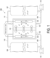
- FIG. 1 is a schematic view showing a redox flow battery according to an embodiment of the present invention.
- a redox flow battery 100 is connected to a power generation unit and a load such as a power system or a consumer typically via an AC/DC converter, and is charged using the power generation unit as a power source and discharged using the load as a power supply target.
- the power generation unit include a solar power generator and a wind power generator as well as a general power plant.
- a battery system described below which includes the redox flow battery 100 and a circulation mechanism for circulating an electrolyte in the redox flow battery 100, is constructed.
- the circulation mechanism include a tank, a pipe, and a pump.
- the redox flow battery 100 includes a positive electrode cell 102 containing a positive electrode 104, a negative electrode cell 103 containing a negative electrode 105, and a diaphragm 101 that separates the positive electrode cell 102 and the negative electrode cell 103 and allows ions to permeate therethrough as appropriate.
- a positive electrode electrolyte tank 106 is connected via pipes 108 and 110.
- a negative electrode electrolyte tank 107 is connected via pipes 109 and 111.
- the pipe 108 is provided with a pump 112 for circulating the positive electrode electrolyte.
- the pipe 109 is provided with a pump 113 for circulating the negative electrode electrolyte.
- the positive electrode electrolyte in the positive electrode electrolyte tank 106 is circulated and supplied to the positive electrode cell 102 (positive electrode 104) using the pipes 108 and 110 and the pump 112, and the negative electrode electrolyte in the negative electrode electrolyte tank 107 is circulated and supplied to the negative electrode cell 103 (negative electrode 105) using the pipes 109 and 111 and the pump 113.
- the redox flow battery 100 is charged and discharged in accordance with a valence change reaction of metal ions serving as an active material in the positive electrode electrolyte in the positive electrode cell 102 and a valence change reaction of metal ions serving as an active material in the negative electrode electrolyte in the negative electrode cell 103.
- the diaphragm 101 examples include a porous material made of magnesium oxide (MgO). Alternatively, glass fibers having a high void ratio may be used as the diaphragm 101.
- the positive electrode electrolyte contains trivalent titanium ions (Ti 3+ ) and tetravalent titanium ions (Ti 4+ ) as active materials
- the negative electrode electrolyte contains divalent titanium ions (Ti 2+ ) and trivalent titanium ions (Ti 3+ ) as active materials. Therefore, the redox flow battery 100 normally functions as a battery even when it includes a diaphragm that has a large surface roughness and allows a substance to easily move physically.
- the redox flow battery 100 functions as a battery even if the positive electrode electrolyte and the negative electrode electrolyte permeate through the diaphragm 101 and are mixed to some extent. Therefore, it can be said that the redox flow battery 100 is resistant to cross-contamination. That is, the redox flow battery 100 has excellent resilience against cross-contamination. It is considered that such a feature of excellent resilience becomes more advantageous as the power storage scale increases.
- Examples of the positive electrode 104 and the negative electrode 105 include electrodes made of carbon materials such as graphite, fullerene, and carbon nanotubes.
- the positive electrode electrolyte and the negative electrode electrolyte are molten salts.
- the molten salts are not particularly limited as long as they have a low melting point, but are each preferably a molten salt of lithium chloride and potassium chloride (LiCl-KCl) (melting point: from 350°C to 500°C), a molten salt of sodium chloride and potassium chloride (NaCl-KCl) (melting point: from 700°C to 750°C), a molten salt of magnesium chloride, sodium chloride, and potassium chloride (MgCl 2 -NaCl-KCl) (melting point: from 400°C to 500°C), a molten salt of lithium fluoride, sodium fluoride, and potassium fluoride (LiF-NaF-KF) (melting point: from 460°C to 600°C), or a molten salt of lithium chloride, potassium chloride, and cesium chloride (LiCl-KCl-C
- the mixing ratio between lithium chloride and potassium chloride is preferably from 4:6 to 6:4 in terms of molar ratio.
- the positive electrode electrolyte and the negative electrode electrolyte can dissolve a predetermined amount of titanium ions described later.
- the mixing ratio between sodium chloride and potassium chloride is preferably from 4:6 to 6:4 in terms of molar ratio.
- the positive electrode electrolyte and the negative electrode electrolyte can dissolve a predetermined amount of titanium ions described later.
- the mixing ratio between magnesium chloride, sodium chloride, and potassium chloride is preferably from 6:2:2 to 4:3:3 in molar ratio.
- the positive electrode electrolyte and the negative electrode electrolyte can dissolve a predetermined amount of titanium ions described later.
- the mixing ratio between lithium fluoride, sodium fluoride, and potassium fluoride is preferably from 5:1:4 to 4:1:5 in terms of molar ratio.
- the positive electrode electrolyte and the negative electrode electrolyte can dissolve a predetermined amount of titanium ions described later.
- the mixing ratio between lithium chloride, potassium chloride, and cesium chloride is preferably from 5:2:3 to 6:2:2 in terms of molar ratio.
- the positive electrode electrolyte and the negative electrode electrolyte can dissolve a predetermined amount of titanium ions described later.
- the positive electrode electrolyte contains trivalent titanium ions (Ti 3+ ) and tetravalent titanium ions (Ti 4+ ) as active materials.
- the trivalent titanium ions (Ti 3+ ) and the tetravalent titanium ions (Ti 4+ ) originate from, for example, titanium(III) chloride (TiCl 3 ) dissolved in the positive electrode electrolyte.
- Fluoride ions (F - ) may be introduced into the electrolyte.
- the content of trivalent titanium ions (Ti 3+ ) in the positive electrode electrolyte is preferably from 0.5 mol/L to 8 mol/L, more preferably from 1 mol/L to 6 mol/L, and still more preferably from 2 mol/L to 5 mol/L. If the content of trivalent titanium ions (Ti 3+ ) in the positive electrode electrolyte is less than the lower limit, the battery cannot be sufficiently charged. If the content of trivalent titanium ions (Ti 3+ ) in the positive electrode electrolyte exceeds the upper limit, the titanium halide does not completely dissolve in the molten salt and precipitates.
- the content of tetravalent titanium ions (Ti 4+ ) in the positive electrode electrolyte is preferably from 0.5 mol/L to 8 mol/L, more preferably from 1 mol/L to 6 mol/L, and still more preferably from 2 mol/L to 5 mol/L. If the content of tetravalent titanium ions (Ti 4+ ) in the positive electrode electrolyte is less than the lower limit, the current density that can be extracted at the time of discharge is low. If the content of tetravalent titanium ions (Ti 4+ ) in the positive electrode electrolyte exceeds the upper limit, the titanium halide does not completely dissolve in the molten salt, resulting in evaporation loss.
- the content of trivalent titanium ions (Ti 3+ ) and the content of tetravalent titanium ions (Ti 4+ ) in the positive electrode electrolyte may be equal to or different from each other.
- the negative electrode electrolyte contains divalent titanium ions (Ti 2+ ) and trivalent titanium ions (Ti 3+ ) as active materials.
- the divalent titanium ions (Ti 2+ ) and the trivalent titanium ions (Ti 3+ ) originate from, for example, titanium(III) chloride (TiCl 3 ) dissolved in the negative electrode electrolyte.
- Fluoride ions (F - ) may be introduced into the electrolyte.
- the content of divalent titanium ions (Ti 2+ ) in the negative electrode electrolyte is preferably from 0.5 mol/L to 8 mol/L, more preferably from 1 mol/L to 6 mol/L, and still more preferably from 2 mol/L to 5 mol/L. If the content of divalent titanium ions (Ti 2+ ) in the negative electrode electrolyte is less than the lower limit, the current density that can be extracted at the time of discharge is low. If the content of divalent titanium ions (Ti 2+ ) in the negative electrode electrolyte exceeds the upper limit, the titanium halide does not completely dissolve in the molten salt and precipitates.
- the content of trivalent titanium ions (Ti 3+ ) in the negative electrode electrolyte is preferably from 0.5 mol/L to 8 mol/L, more preferably from 1 mol/L to 6 mol/L, and still more preferably from 2 mol/L to 5 mol/L. If the content of trivalent titanium ions (Ti 3+ ) in the negative electrode electrolyte is less than the lower limit, the battery cannot be sufficiently charged. If the content of trivalent titanium ions (Ti 3+ ) in the negative electrode electrolyte exceeds the upper limit, the titanium halide does not completely dissolve in the molten salt and precipitates.
- the content of divalent titanium ions (Ti 2+ ) and the content of trivalent titanium ions (Ti 3+ ) in the negative electrode electrolyte may be equal to or different from each other.
- an electron reaction represented by the following formula (1) occurs at the positive electrode.
- the potential of the positive electrode is -0.3 V vs. Cl 2 /Cl - due to this electron reaction.
- an electron reaction represented by the following formula (2) occurs at the negative electrode.
- the potential of the negative electrode is -2.1 V vs. Cl 2 /Cl - due to this electron reaction.
- the redox flow battery 100 generates an electromotive force by the occurrence of the electron reaction at the positive electrode and the electron reaction at the negative electrode described above.
- the electromotive force of the redox flow battery 100 corresponds to a potential difference between the potential of the positive electrode (-0.3 V vs. Cl 2 /Cl - ) and the potential of the negative electrode (-2.1 V vs. Cl 2 /Cl - ), and is 1.8 V. Since the electromotive force of the known vanadium ion redox flow battery is 1.4 V, the electromotive force of the redox flow battery 100 is about 29% higher than that of the vanadium ion redox flow battery.
- the redox flow battery 100 In order for the redox flow battery 100 to generate an electromotive force, it is necessary to heat the molten salt in the positive electrode cell 102 and the molten salt in the negative electrode cell 103 to a temperature equal to or higher than the above-mentioned melting points of molten salts. After the electron reaction at the positive electrode and the electron reaction at the negative electrode as described above start, the molten salts can be maintained at a temperature equal to or higher than the melting points by the heat of such reactions, so that heating of the molten salts is unnecessary. In order to maintain the molten salts at a temperature equal to or higher than the melting points, it is preferable to provide a heat insulating material on the outer periphery of the positive electrode cell 102 and the negative electrode cell 103.
- the concentrations of divalent titanium ions (Ti 2+ ), trivalent titanium ions (Ti 3+ ), and tetravalent titanium ions (Ti 4+ ) in the positive electrode electrolyte and the negative electrode electrolyte can be increased.
- a high current density can be extracted.
- the redox flow battery 100 can achieve a high current density (rapid charge and large output) at the time of charge and discharge.
- the redox flow battery 100 is not constrained by decomposition of water, and has a higher electromotive force than that of a vanadium ion redox flow battery.
- the redox flow battery 100 has a higher electromotive force than that of the vanadium ion redox flow battery, it is possible to reduce the number of stacked battery cells, significantly reduce the cost of active materials (divalent titanium ions (Ti 2+ ), trivalent titanium ions (Ti 3+ ), and tetravalent titanium ions (Ti 4+ )) supplied to the positive electrode cell 102 and the negative electrode cell 103, and increase the space utilization efficiency.
- active materials divalent titanium ions (Ti 2+ ), trivalent titanium ions (Ti 3+ ), and tetravalent titanium ions (Ti 4+ )
- a LiCl-KCl molten salt containing 0.3 mol/L of TiCl 3 was placed in an electrode cell.
- a graphite electrode was used as a working electrode, an Ag + /Ag electrode was used as a reference electrode, and a graphite electrode was used as a counter electrode.
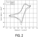
- the working electrode, the reference electrode, and the counter electrode were connected to a potentiostat device, the working electrode, the reference electrode, and the counter electrode were immersed in the LiCl-KCl molten salt containing TiCl 3 , the potential was increased and decreased at a sweep rate of 200 mV/s or 400 mV/s, and the current value was measured.
- the temperature of the LiCl-KCl molten salt containing TiCl 3 during the measurement was set to 450°C.
- FIG. 2 shows the resulting cyclic voltammogram.
- the potential was swept in a square wave form at the working electrode to measure the response current, and the electrode reaction occurring was analyzed on the basis of the potential and the current.
- the temperature of the LiCl-KCl molten salt containing TiCl 3 during the measurement was set to 450°C.
- FIG. 3 shows the resulting square wave voltammogram.
- a LiCl-KCl molten salt containing 0.3 mol/L of TiCl 3 was placed in an electrode cell.
- a graphite electrode was used as a working electrode, an Ag + /Ag electrode was used as a reference electrode for conversion in terms of chlorine evolution, and a graphite electrode was used as a counter electrode.
- the working electrode, the reference electrode, and the counter electrode were connected to a potentiostat device, the working electrode, the reference electrode, and the counter electrode were immersed in the LiCl-KCl molten salt containing TiCl 3 , the potential was increased and decreased at a sweep rate of 200 mV/s to 400 mV/s, and the current value was measured.
- the temperature of the LiCl-KCl molten salt containing TiCl 3 during the measurement was set to 450°C.
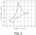
- FIG. 4 shows the resulting cyclic voltammogram.
- the potential was swept in a square wave form at the working electrode to measure the response current, and the electrode reaction occurring was analyzed on the basis of the potential and the current.
- the temperature of the LiCl-KCl molten salt containing TiCl 3 during the measurement was set to 450°C.
- FIG. 5 shows the resulting square wave voltammogram.
- a redox flow battery including the electrode cell of Example 1 as a positive electrode cell and the electrode cell of Example 2 as a negative electrode cell has an electromotive force of 1.8 V.
- a LiCl-KCl molten salt containing 0.3 mol/L of TiCl 3 was placed in an electrode cell.
- An electrode made of carbon fiber cloth was used as a positive electrode current collector, and a crucible graphite electrode was used as a negative electrode current collector.
- the positive electrode and the negative electrode were immersed in the LiCl-KCl molten salt containing TiCl 3 , and the charge capacity and the discharge capacity were measured with increasing and decreasing the voltage at a current density of 10 mA/cm 2 .
- the electrodes were charged to 2 V and discharged to 1.1 V.
- the temperature of the LiCl-KCl molten salt containing TiCl 3 during the measurement was set to 450°C.
- FIG. 6 shows the resulting charge-discharge curves.
- a LiCl-KCl molten salt containing 0.3 mol/L of TiCl 3 was placed in an electrode cell.
- An electrode made of carbon fiber cloth was used as a working electrode, and a crucible graphite electrode was used as a negative electrode current collector.
- the positive electrode and the negative electrode were immersed in the LiCl-KCl molten salt containing TiCl 3 , and the charge capacity and the discharge capacity were measured with increasing and decreasing the voltage at a current density of 10 mA/cm 2 .
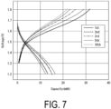
- the electrodes were charged to 1.8 V and discharged to 1.2 V.
- the temperature of the LiCl-KCl molten salt containing TiCl 3 during the measurement was set to 450°C.
- FIG. 7 shows the resulting charge-discharge curves.
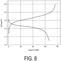
- a redox flow battery including the electrode cell of Example 3 as a positive electrode cell, the electrode cell of Example 4 as a negative electrode cell, and a diaphragm made of magnesium oxide and interposed between the positive electrode cell and the negative electrode cell was produced.
- the electrodes in the positive electrode cell and the negative electrode cell were connected to an electrochemical measurement device, the electrodes in the positive electrode cell and the negative electrode cell were immersed in the LiCl-KCl molten salt containing TiCl 3 , and the charge capacity and the discharge capacity were measured with increasing and decreasing the voltage at a current density of 10 mA/cm 2 .
- the electrodes were charged to 2 V and discharged to 1.1 V.
- the temperature of the LiCl-KCl molten salt containing TiCl 3 during the measurement was set to 450°C.
- FIG. 8 shows the resulting charge-discharge curves.
- a battery cell including a positive electrode cell having a positive electrode, a negative electrode cell having a negative electrode, and a diaphragm interposed between the positive electrode cell and the negative electrode cell was produced.
- An electrode made of a graphite rod having a diameter of 10 mm was used as the positive electrode, and an electrode made of a graphite crucible having a diameter of 50 mm was used as the negative electrode.
- the positive electrode and the negative electrode were connected to an electrochemical measurement device, the positive electrode and the negative electrode were immersed in the aqueous sulfuric acid solution, and the charge capacity and the discharge capacity were measured with increasing and decreasing the voltage at a current density of 10 mA/cm 2 .
- the electrodes were charged to 1.7 V and discharged to 0.7 V.
- the temperature of the aqueous sulfuric acid solution during the measurement was set to 20°C.
- FIG. 9 shows the resulting charge-discharge curves.
- a battery cell including a positive electrode cell having a positive electrode, a negative electrode cell having a negative electrode, and a diaphragm interposed between the positive electrode cell and the negative electrode cell was produced.
- a LiCl-KCl molten salt containing 0.5 mol/L of TiCl 3 was placed in the negative electrode cell.
- a LiCl-KCl molten salt containing 0.5 mol/L of TiCl 2 was placed in the positive electrode cell.
- An electrode made of a graphite net having a diameter of 10 mm and a graphite rod having a diameter of 10 mm was used as the positive electrode, and an electrode made of a graphite crucible having a diameter of 50 mm was used as the negative electrode.
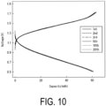
- the positive electrode and the negative electrode were connected to an electrochemical measurement device, the positive electrode was immersed in the LiCl-KCl molten salt containing 0.5 mol/L of TiCl 2 , the negative electrode was immersed in the LiCl-KCl molten salt containing 0.5 mol/L of TiCl 3 , and the charge capacity and the discharge capacity were measured with increasing and decreasing the voltage at a current density of 40 mA/cm 3 . The electrodes were charged to 1.7 V and discharged to 0.5 V.
- the temperature of the molten salts during the measurement was set to 450°C.
- FIG. 10 shows the resulting charge-discharge curves.
- a battery cell including a positive electrode cell having a positive electrode, a negative electrode cell having a negative electrode, and a diaphragm interposed between the positive electrode cell and the negative electrode cell was produced.
- a LiCl-KCl molten salt containing 1.5 mol/L of TiCl 3 was placed in the negative electrode cell.
- a LiCl-KCl molten salt containing 1.5 mol/L of TiCl 2 was placed in the positive electrode cell.
- An electrode made of a graphite net having a diameter of 10 mm and a graphite rod having a diameter of 10 mm was used as the positive electrode, and an electrode made of a graphite crucible having a diameter of 50 mm was used as the negative electrode.
- the positive electrode and the negative electrode were connected to an electrochemical measurement device, the positive electrode was immersed in the LiCl-KCl molten salt containing 1.5 mol/L of TiCl 2 , the negative electrode was immersed in the LiCl-KCl molten salt containing 1.5 mol/L of TiCl 3 , and the charge capacity and the discharge capacity were measured with increasing and decreasing the voltage at a current density of 10 mA/cm 3 .
- the electrodes were charged to 1.8 V and discharged to 0.5 V.
- the temperature of the molten salts during the measurement was set to 400°C.
- FIG. 11 shows the resulting charge-discharge curves.
- a battery cell including a positive electrode cell having a positive electrode, a negative electrode cell having a negative electrode, and a diaphragm interposed between the positive electrode cell and the negative electrode cell was produced.
- a NaCl-KCl-MgCl 2 molten salt containing 1.5 mol/L of TiCl 3 was placed in the negative electrode cell.
- a NaCl-KCl-MgCl 2 molten salt containing 1.5 mol/L of TiCl 2 was placed in the positive electrode cell.
- An electrode made of a graphite net having a diameter of 10 mm and a graphite rod having a diameter of 10 mm was used as the positive electrode, and an electrode made of a graphite crucible having a diameter of 50 mm was used as the negative electrode.
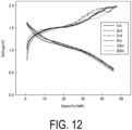
- the positive electrode and the negative electrode were connected to an electrochemical measurement device, the positive electrode was immersed in the NaCl-KCl-MgCl 2 molten salt containing 1.5 mol/L of TiCl 2 , the negative electrode was immersed in the NaCl-KCl-MgCl 2 molten salt containing 1.5 mol/L of TiCl 3 , and the charge capacity and the discharge capacity were measured with increasing and decreasing the voltage at a current density of 15 mA/cm 3 .
- the electrodes were charged to 2.0 V and discharged to 0.5 V.
- the temperature of the molten salts during the measurement was set to 480°C.
- FIG. 12 shows the resulting charge-discharge curves.
- a large-capacity storage battery system suitable for ultra-large-scale power generation can be created as a storage battery system for power generation using renewable energy.
Landscapes
- Engineering & Computer Science (AREA)
- Manufacturing & Machinery (AREA)
- Chemical & Material Sciences (AREA)
- Chemical Kinetics & Catalysis (AREA)
- Electrochemistry (AREA)
- General Chemical & Material Sciences (AREA)
- Life Sciences & Earth Sciences (AREA)
- Sustainable Development (AREA)
- Sustainable Energy (AREA)
- Fuel Cell (AREA)
Abstract
Description
- The present invention relates to a redox flow battery.
- The present application claims priority on the basis of
Japanese Patent Application No. 2022-058258 filed in Japan on March 31, 2022 - Currently, introduction of renewable energy is rapidly accelerated. Meanwhile, there has been an issue regarding how to store and release electricity generated from renewable energy. An example of known techniques for storing and releasing electricity includes a vanadium ion redox flow battery utilizing an electrode reaction of vanadium ions (see, for example, Patent Document 1).
- Patent Document 1:
WO 2011/111717 - However, the vanadium ion redox flow battery uses an aqueous solution as an electrolyte. Therefore, there has been a disadvantage that an active material has low solubility in the electrolyte and the current density that can be extracted from the battery is low.
- The present invention has been made in view of the above-mentioned circumstances, and an object thereof is to provide a redox flow battery from which a high current density can be extracted.
- To solve the above-mentioned issue, the present invention has the following aspects.
- [1] A redox flow battery that is charged and discharged by supply of a positive electrode electrolyte and a negative electrode electrolyte to a battery cell including a positive electrode, a negative electrode, and a diaphragm interposed between the positive electrode and the negative electrode, wherein:
- the positive electrode electrolyte and the negative electrode electrolyte are molten salts,
- the positive electrode electrolyte contains a trivalent titanium ion and a tetravalent titanium ion, and
- the negative electrode electrolyte contains a divalent titanium ion and a trivalent titanium ion.
- [2] The redox flow battery according to [1], wherein each of the molten salts is a molten salt of lithium chloride and potassium chloride, a molten salt of sodium chloride and potassium chloride, a molten salt of magnesium chloride, sodium chloride, and potassium chloride, or a molten salt of lithium fluoride, sodium fluoride, and potassium fluoride.
- According to the present invention, it is possible to provide a redox flow battery from which a high current density can be extracted.
-
-
FIG. 1 is a schematic view illustrating a redox flow battery according to an embodiment of the present invention. -
FIG. 2 is a diagram showing a cyclic voltammogram in Example 1. -
FIG. 3 is a diagram showing a square wave voltammogram in Example 1. -
FIG. 4 is a diagram showing a cyclic voltammogram in Example 2. -
FIG. 5 is a diagram showing a square wave voltammogram in Example 2. -
FIG. 6 is a diagram showing charge-discharge curves in Example 3. -
FIG. 7 is a diagram showing charge-discharge curves in Example 4. -
FIG. 8 is a diagram showing charge-discharge curves in Example 5. -
FIG. 9 is a diagram showing charge-discharge curves in Comparative Example. -
FIG. 10 is a diagram showing charge-discharge curves in Example 6. -
FIG. 11 is a diagram showing charge-discharge curves in Example 7. -
FIG. 12 is a diagram showing charge-discharge curves in Example 8. - Hereinafter, with reference to
FIG. 1 , a redox flow battery according to the present invention is described by way of an embodiment. However, the present invention is not limited to the embodiment described below. - A word "to" indicating a numerical range means that numerical values described before and after the word "to" are included in the numerical range as a lower limit and an upper limit.
-
FIG. 1 is a schematic view showing a redox flow battery according to an embodiment of the present invention. - As shown in
FIG. 1 , aredox flow battery 100 is connected to a power generation unit and a load such as a power system or a consumer typically via an AC/DC converter, and is charged using the power generation unit as a power source and discharged using the load as a power supply target. Examples of the power generation unit include a solar power generator and a wind power generator as well as a general power plant. In order to perform the above-mentioned charge and discharge, a battery system described below, which includes theredox flow battery 100 and a circulation mechanism for circulating an electrolyte in theredox flow battery 100, is constructed. Examples of the circulation mechanism include a tank, a pipe, and a pump. - The
redox flow battery 100 includes apositive electrode cell 102 containing apositive electrode 104, anegative electrode cell 103 containing anegative electrode 105, and adiaphragm 101 that separates thepositive electrode cell 102 and thenegative electrode cell 103 and allows ions to permeate therethrough as appropriate. To thepositive electrode cell 102, a positiveelectrode electrolyte tank 106 is connected viapipes negative electrode cell 103, a negativeelectrode electrolyte tank 107 is connected viapipes pipe 108 is provided with apump 112 for circulating the positive electrode electrolyte. Thepipe 109 is provided with apump 113 for circulating the negative electrode electrolyte. - In the
redox flow battery 100, the positive electrode electrolyte in the positiveelectrode electrolyte tank 106 is circulated and supplied to the positive electrode cell 102 (positive electrode 104) using thepipes pump 112, and the negative electrode electrolyte in the negativeelectrode electrolyte tank 107 is circulated and supplied to the negative electrode cell 103 (negative electrode 105) using thepipes pump 113. As a result, theredox flow battery 100 is charged and discharged in accordance with a valence change reaction of metal ions serving as an active material in the positive electrode electrolyte in thepositive electrode cell 102 and a valence change reaction of metal ions serving as an active material in the negative electrode electrolyte in thenegative electrode cell 103. - Examples of the
diaphragm 101 include a porous material made of magnesium oxide (MgO). Alternatively, glass fibers having a high void ratio may be used as thediaphragm 101. As described later, in theredox flow battery 100, the positive electrode electrolyte contains trivalent titanium ions (Ti3+) and tetravalent titanium ions (Ti4+) as active materials, and the negative electrode electrolyte contains divalent titanium ions (Ti2+) and trivalent titanium ions (Ti3+) as active materials. Therefore, theredox flow battery 100 normally functions as a battery even when it includes a diaphragm that has a large surface roughness and allows a substance to easily move physically. In addition, theredox flow battery 100 functions as a battery even if the positive electrode electrolyte and the negative electrode electrolyte permeate through thediaphragm 101 and are mixed to some extent. Therefore, it can be said that theredox flow battery 100 is resistant to cross-contamination. That is, theredox flow battery 100 has excellent resilience against cross-contamination. It is considered that such a feature of excellent resilience becomes more advantageous as the power storage scale increases. - Examples of the
positive electrode 104 and thenegative electrode 105 include electrodes made of carbon materials such as graphite, fullerene, and carbon nanotubes. - The positive electrode electrolyte and the negative electrode electrolyte are molten salts. The molten salts are not particularly limited as long as they have a low melting point, but are each preferably a molten salt of lithium chloride and potassium chloride (LiCl-KCl) (melting point: from 350°C to 500°C), a molten salt of sodium chloride and potassium chloride (NaCl-KCl) (melting point: from 700°C to 750°C), a molten salt of magnesium chloride, sodium chloride, and potassium chloride (MgCl2-NaCl-KCl) (melting point: from 400°C to 500°C), a molten salt of lithium fluoride, sodium fluoride, and potassium fluoride (LiF-NaF-KF) (melting point: from 460°C to 600°C), or a molten salt of lithium chloride, potassium chloride, and cesium chloride (LiCl-KCl-CsCl) (melting point: from 270°C to 400°C).
- In the molten salt of lithium chloride and potassium chloride (LiCl-KCl), the mixing ratio between lithium chloride and potassium chloride is preferably from 4:6 to 6:4 in terms of molar ratio. When the mixing ratio between lithium chloride and potassium chloride is within the above range, the positive electrode electrolyte and the negative electrode electrolyte can dissolve a predetermined amount of titanium ions described later.
- In the molten salt of sodium chloride and potassium chloride (NaCl-KCl), the mixing ratio between sodium chloride and potassium chloride is preferably from 4:6 to 6:4 in terms of molar ratio. When the mixing ratio between sodium chloride and potassium chloride is within the above range, the positive electrode electrolyte and the negative electrode electrolyte can dissolve a predetermined amount of titanium ions described later.
- In the molten salt of magnesium chloride, sodium chloride, and potassium chloride (MgCl2-NaCl-KCl), the mixing ratio between magnesium chloride, sodium chloride, and potassium chloride is preferably from 6:2:2 to 4:3:3 in molar ratio. When the mixing ratio between magnesium chloride, sodium chloride, and potassium chloride is within the above range, the positive electrode electrolyte and the negative electrode electrolyte can dissolve a predetermined amount of titanium ions described later.
- In the molten salt of lithium fluoride, sodium fluoride, and potassium fluoride (LiF-NaF-KF), the mixing ratio between lithium fluoride, sodium fluoride, and potassium fluoride is preferably from 5:1:4 to 4:1:5 in terms of molar ratio. When the mixing ratio between lithium fluoride, sodium fluoride, and potassium fluoride is within the above range, the positive electrode electrolyte and the negative electrode electrolyte can dissolve a predetermined amount of titanium ions described later.
- In the molten salt of lithium chloride, potassium chloride, and cesium chloride (LiCl-KCl-CsCl), the mixing ratio between lithium chloride, potassium chloride, and cesium chloride is preferably from 5:2:3 to 6:2:2 in terms of molar ratio. When the mixing ratio between lithium chloride, potassium chloride, and cesium chloride is within the above range, the positive electrode electrolyte and the negative electrode electrolyte can dissolve a predetermined amount of titanium ions described later.
- The positive electrode electrolyte contains trivalent titanium ions (Ti3+) and tetravalent titanium ions (Ti4+) as active materials. The trivalent titanium ions (Ti3+) and the tetravalent titanium ions (Ti4+) originate from, for example, titanium(III) chloride (TiCl3) dissolved in the positive electrode electrolyte. Fluoride ions (F-) may be introduced into the electrolyte.
- The content of trivalent titanium ions (Ti3+) in the positive electrode electrolyte is preferably from 0.5 mol/L to 8 mol/L, more preferably from 1 mol/L to 6 mol/L, and still more preferably from 2 mol/L to 5 mol/L. If the content of trivalent titanium ions (Ti3+) in the positive electrode electrolyte is less than the lower limit, the battery cannot be sufficiently charged. If the content of trivalent titanium ions (Ti3+) in the positive electrode electrolyte exceeds the upper limit, the titanium halide does not completely dissolve in the molten salt and precipitates.
- The content of tetravalent titanium ions (Ti4+) in the positive electrode electrolyte is preferably from 0.5 mol/L to 8 mol/L, more preferably from 1 mol/L to 6 mol/L, and still more preferably from 2 mol/L to 5 mol/L. If the content of tetravalent titanium ions (Ti4+) in the positive electrode electrolyte is less than the lower limit, the current density that can be extracted at the time of discharge is low. If the content of tetravalent titanium ions (Ti4+) in the positive electrode electrolyte exceeds the upper limit, the titanium halide does not completely dissolve in the molten salt, resulting in evaporation loss.
- The content of trivalent titanium ions (Ti3+) and the content of tetravalent titanium ions (Ti4+) in the positive electrode electrolyte may be equal to or different from each other.
- The negative electrode electrolyte contains divalent titanium ions (Ti2+) and trivalent titanium ions (Ti3+) as active materials. The divalent titanium ions (Ti2+) and the trivalent titanium ions (Ti3+) originate from, for example, titanium(III) chloride (TiCl3) dissolved in the negative electrode electrolyte. Fluoride ions (F-) may be introduced into the electrolyte.
- The content of divalent titanium ions (Ti2+) in the negative electrode electrolyte is preferably from 0.5 mol/L to 8 mol/L, more preferably from 1 mol/L to 6 mol/L, and still more preferably from 2 mol/L to 5 mol/L. If the content of divalent titanium ions (Ti2+) in the negative electrode electrolyte is less than the lower limit, the current density that can be extracted at the time of discharge is low. If the content of divalent titanium ions (Ti2+) in the negative electrode electrolyte exceeds the upper limit, the titanium halide does not completely dissolve in the molten salt and precipitates.
- The content of trivalent titanium ions (Ti3+) in the negative electrode electrolyte is preferably from 0.5 mol/L to 8 mol/L, more preferably from 1 mol/L to 6 mol/L, and still more preferably from 2 mol/L to 5 mol/L. If the content of trivalent titanium ions (Ti3+) in the negative electrode electrolyte is less than the lower limit, the battery cannot be sufficiently charged. If the content of trivalent titanium ions (Ti3+) in the negative electrode electrolyte exceeds the upper limit, the titanium halide does not completely dissolve in the molten salt and precipitates.
- The content of divalent titanium ions (Ti2+) and the content of trivalent titanium ions (Ti3+) in the negative electrode electrolyte may be equal to or different from each other.
- In the
redox flow battery 100, an electron reaction represented by the following formula (1) occurs at the positive electrode. The potential of the positive electrode is -0.3 V vs. Cl2/Cl-due to this electron reaction.
- In the
redox flow battery 100, an electron reaction represented by the following formula (2) occurs at the negative electrode. The potential of the negative electrode is -2.1 V vs. Cl2/Cl-due to this electron reaction.
- The
redox flow battery 100 generates an electromotive force by the occurrence of the electron reaction at the positive electrode and the electron reaction at the negative electrode described above. The electromotive force of theredox flow battery 100 corresponds to a potential difference between the potential of the positive electrode (-0.3 V vs. Cl2/Cl-) and the potential of the negative electrode (-2.1 V vs. Cl2/Cl-), and is 1.8 V. Since the electromotive force of the known vanadium ion redox flow battery is 1.4 V, the electromotive force of theredox flow battery 100 is about 29% higher than that of the vanadium ion redox flow battery. - In order for the
redox flow battery 100 to generate an electromotive force, it is necessary to heat the molten salt in thepositive electrode cell 102 and the molten salt in thenegative electrode cell 103 to a temperature equal to or higher than the above-mentioned melting points of molten salts. After the electron reaction at the positive electrode and the electron reaction at the negative electrode as described above start, the molten salts can be maintained at a temperature equal to or higher than the melting points by the heat of such reactions, so that heating of the molten salts is unnecessary. In order to maintain the molten salts at a temperature equal to or higher than the melting points, it is preferable to provide a heat insulating material on the outer periphery of thepositive electrode cell 102 and thenegative electrode cell 103. - In the
redox flow battery 100, since the positive electrode electrolyte and the negative electrode electrolyte are molten salts, the concentrations of divalent titanium ions (Ti2+), trivalent titanium ions (Ti3+), and tetravalent titanium ions (Ti4+) in the positive electrode electrolyte and the negative electrode electrolyte can be increased. As a result, a high current density can be extracted. In other words, theredox flow battery 100 can achieve a high current density (rapid charge and large output) at the time of charge and discharge. In addition, since the positive electrode electrolyte and the negative electrode electrolyte are molten salts, theredox flow battery 100 is not constrained by decomposition of water, and has a higher electromotive force than that of a vanadium ion redox flow battery. - In addition, since the
redox flow battery 100 has a higher electromotive force than that of the vanadium ion redox flow battery, it is possible to reduce the number of stacked battery cells, significantly reduce the cost of active materials (divalent titanium ions (Ti2+), trivalent titanium ions (Ti3+), and tetravalent titanium ions (Ti4+)) supplied to thepositive electrode cell 102 and thenegative electrode cell 103, and increase the space utilization efficiency. - Although the embodiment of the present invention has been described above, the present invention is not limited to the above-mentioned embodiment, and various modifications can be made.
- Hereinafter, advantageous effects of the present invention are made more apparent with reference to examples. Note that the present invention is not limited to the following examples, and can be carried out with appropriate modifications without changing the gist of the invention.
- A LiCl-KCl molten salt containing 0.3 mol/L of TiCl3 was placed in an electrode cell.
- A graphite electrode was used as a working electrode, an Ag+/Ag electrode was used as a reference electrode, and a graphite electrode was used as a counter electrode.
- The working electrode, the reference electrode, and the counter electrode were connected to a potentiostat device, the working electrode, the reference electrode, and the counter electrode were immersed in the LiCl-KCl molten salt containing TiCl3, the potential was increased and decreased at a sweep rate of 200 mV/s or 400 mV/s, and the current value was measured.
- The temperature of the LiCl-KCl molten salt containing TiCl3 during the measurement was set to 450°C.
- In this measurement, the electron reaction represented by the formula (1) occurs.
-
FIG. 2 shows the resulting cyclic voltammogram. - The potential was swept in a square wave form at the working electrode to measure the response current, and the electrode reaction occurring was analyzed on the basis of the potential and the current.
- The temperature of the LiCl-KCl molten salt containing TiCl3 during the measurement was set to 450°C.
- In this measurement, the electron reaction represented by the formula (1) occurs.
-
FIG. 3 shows the resulting square wave voltammogram. - From the results shown in
FIGS. 2 and3 , it was found that the potential of the LiCl-KCl molten salt containing TiCl3 was -0.3 V vs. Cl2/Cl-. - A LiCl-KCl molten salt containing 0.3 mol/L of TiCl3 was placed in an electrode cell.
- A graphite electrode was used as a working electrode, an Ag+/Ag electrode was used as a reference electrode for conversion in terms of chlorine evolution, and a graphite electrode was used as a counter electrode.
- The working electrode, the reference electrode, and the counter electrode were connected to a potentiostat device, the working electrode, the reference electrode, and the counter electrode were immersed in the LiCl-KCl molten salt containing TiCl3, the potential was increased and decreased at a sweep rate of 200 mV/s to 400 mV/s, and the current value was measured.
- The temperature of the LiCl-KCl molten salt containing TiCl3 during the measurement was set to 450°C.
- In this measurement, an electron reaction represented by the formula (2) and an electron reaction represented by the following formula (3) occurs.
-
FIG. 4 shows the resulting cyclic voltammogram.
- The potential was swept in a square wave form at the working electrode to measure the response current, and the electrode reaction occurring was analyzed on the basis of the potential and the current.
- The temperature of the LiCl-KCl molten salt containing TiCl3 during the measurement was set to 450°C.
- In this measurement, an electron reaction represented by the formula (2) and an electron reaction represented by the formula (3) occur.
-
FIG. 5 shows the resulting square wave voltammogram. - From the results shown in
FIGS. 4 and5 , it was found that the potential of the LiCl-KCl molten salt containing TiCl3 was -2.1 V in the electron reaction represented by the formula (2) and -2.4 V in the electron reaction represented by the formula (3). - Therefore, it was found that a redox flow battery including the electrode cell of Example 1 as a positive electrode cell and the electrode cell of Example 2 as a negative electrode cell has an electromotive force of 1.8 V.
- A LiCl-KCl molten salt containing 0.3 mol/L of TiCl3 was placed in an electrode cell.
- An electrode made of carbon fiber cloth was used as a positive electrode current collector, and a crucible graphite electrode was used as a negative electrode current collector.
- The positive electrode and the negative electrode were immersed in the LiCl-KCl molten salt containing TiCl3, and the charge capacity and the discharge capacity were measured with increasing and decreasing the voltage at a current density of 10 mA/cm2. The electrodes were charged to 2 V and discharged to 1.1 V.
- The temperature of the LiCl-KCl molten salt containing TiCl3 during the measurement was set to 450°C.
- In this measurement, the electron reaction represented by the formula (1) occurs.
-
FIG. 6 shows the resulting charge-discharge curves. - From the results shown in
FIG. 6 , it was found that the charge curve and the discharge curve are substantially reversed. - A LiCl-KCl molten salt containing 0.3 mol/L of TiCl3 was placed in an electrode cell.
- An electrode made of carbon fiber cloth was used as a working electrode, and a crucible graphite electrode was used as a negative electrode current collector. The positive electrode and the negative electrode were immersed in the LiCl-KCl molten salt containing TiCl3, and the charge capacity and the discharge capacity were measured with increasing and decreasing the voltage at a current density of 10 mA/cm2. The electrodes were charged to 1.8 V and discharged to 1.2 V.
- The temperature of the LiCl-KCl molten salt containing TiCl3 during the measurement was set to 450°C.
- In this measurement, the electron reaction represented by the formula (2) occurs.
-
FIG. 7 shows the resulting charge-discharge curves. - From the results shown in
FIG. 7 , it was found that the charge curve and the discharge curve are substantially reversed. - A redox flow battery including the electrode cell of Example 3 as a positive electrode cell, the electrode cell of Example 4 as a negative electrode cell, and a diaphragm made of magnesium oxide and interposed between the positive electrode cell and the negative electrode cell was produced.
- The electrodes in the positive electrode cell and the negative electrode cell were connected to an electrochemical measurement device, the electrodes in the positive electrode cell and the negative electrode cell were immersed in the LiCl-KCl molten salt containing TiCl3, and the charge capacity and the discharge capacity were measured with increasing and decreasing the voltage at a current density of 10 mA/cm2. The electrodes were charged to 2 V and discharged to 1.1 V.
- The temperature of the LiCl-KCl molten salt containing TiCl3 during the measurement was set to 450°C.
-
FIG. 8 shows the resulting charge-discharge curves. - From the results shown in
FIG. 8 , it was found that the charge curve and the discharge curve are substantially reversed. - A battery cell including a positive electrode cell having a positive electrode, a negative electrode cell having a negative electrode, and a diaphragm interposed between the positive electrode cell and the negative electrode cell was produced.
- In the positive electrode cell and the negative electrode cell, a 2 mol/L aqueous sulfuric acid solution containing 1 mol/L vanadyl sulfate (VOSO4) was placed.
- An electrode made of a graphite rod having a diameter of 10 mm was used as the positive electrode, and an electrode made of a graphite crucible having a diameter of 50 mm was used as the negative electrode.
- The positive electrode and the negative electrode were connected to an electrochemical measurement device, the positive electrode and the negative electrode were immersed in the aqueous sulfuric acid solution, and the charge capacity and the discharge capacity were measured with increasing and decreasing the voltage at a current density of 10 mA/cm2. The electrodes were charged to 1.7 V and discharged to 0.7 V.
- The temperature of the aqueous sulfuric acid solution during the measurement was set to 20°C.
-
FIG. 9 shows the resulting charge-discharge curves. - From the results shown in
FIG. 9 , it was found that the charge curve and the discharge curve are not reversed. - A battery cell including a positive electrode cell having a positive electrode, a negative electrode cell having a negative electrode, and a diaphragm interposed between the positive electrode cell and the negative electrode cell was produced.
- A LiCl-KCl molten salt containing 0.5 mol/L of TiCl3 was placed in the negative electrode cell. A LiCl-KCl molten salt containing 0.5 mol/L of TiCl2 was placed in the positive electrode cell.
- An electrode made of a graphite net having a diameter of 10 mm and a graphite rod having a diameter of 10 mm was used as the positive electrode, and an electrode made of a graphite crucible having a diameter of 50 mm was used as the negative electrode.
- The positive electrode and the negative electrode were connected to an electrochemical measurement device, the positive electrode was immersed in the LiCl-KCl molten salt containing 0.5 mol/L of TiCl2, the negative electrode was immersed in the LiCl-KCl molten salt containing 0.5 mol/L of TiCl3, and the charge capacity and the discharge capacity were measured with increasing and decreasing the voltage at a current density of 40 mA/cm3. The electrodes were charged to 1.7 V and discharged to 0.5 V.
- The temperature of the molten salts during the measurement was set to 450°C.
-
FIG. 10 shows the resulting charge-discharge curves. - From the results shown in
FIG. 10 , it was found that the charge curve and the discharge curve are substantially reversed. In addition, even when charge and discharge were repeated, the charge capacity and the discharge capacity decayed little, and it was found that the battery cell was excellent in cycle characteristics. - A battery cell including a positive electrode cell having a positive electrode, a negative electrode cell having a negative electrode, and a diaphragm interposed between the positive electrode cell and the negative electrode cell was produced.
- A LiCl-KCl molten salt containing 1.5 mol/L of TiCl3 was placed in the negative electrode cell. A LiCl-KCl molten salt containing 1.5 mol/L of TiCl2 was placed in the positive electrode cell.
- An electrode made of a graphite net having a diameter of 10 mm and a graphite rod having a diameter of 10 mm was used as the positive electrode, and an electrode made of a graphite crucible having a diameter of 50 mm was used as the negative electrode.
- The positive electrode and the negative electrode were connected to an electrochemical measurement device, the positive electrode was immersed in the LiCl-KCl molten salt containing 1.5 mol/L of TiCl2, the negative electrode was immersed in the LiCl-KCl molten salt containing 1.5 mol/L of TiCl3, and the charge capacity and the discharge capacity were measured with increasing and decreasing the voltage at a current density of 10 mA/cm3. The electrodes were charged to 1.8 V and discharged to 0.5 V.
- The temperature of the molten salts during the measurement was set to 400°C.
-
FIG. 11 shows the resulting charge-discharge curves. - From the results shown in
FIG. 11 , it was found that the charge curve and the discharge curve are substantially reversed. In addition, even when charge and discharge were repeated, the charge capacity and the discharge capacity decayed little, and it was found that the battery cell was excellent in cycle characteristics. - A battery cell including a positive electrode cell having a positive electrode, a negative electrode cell having a negative electrode, and a diaphragm interposed between the positive electrode cell and the negative electrode cell was produced.
- A NaCl-KCl-MgCl2 molten salt containing 1.5 mol/L of TiCl3 was placed in the negative electrode cell. A NaCl-KCl-MgCl2 molten salt containing 1.5 mol/L of TiCl2 was placed in the positive electrode cell.
- An electrode made of a graphite net having a diameter of 10 mm and a graphite rod having a diameter of 10 mm was used as the positive electrode, and an electrode made of a graphite crucible having a diameter of 50 mm was used as the negative electrode.
- The positive electrode and the negative electrode were connected to an electrochemical measurement device, the positive electrode was immersed in the NaCl-KCl-MgCl2 molten salt containing 1.5 mol/L of TiCl2, the negative electrode was immersed in the NaCl-KCl-MgCl2 molten salt containing 1.5 mol/L of TiCl3, and the charge capacity and the discharge capacity were measured with increasing and decreasing the voltage at a current density of 15 mA/cm3. The electrodes were charged to 2.0 V and discharged to 0.5 V.
- The temperature of the molten salts during the measurement was set to 480°C.
-
FIG. 12 shows the resulting charge-discharge curves. - From the results shown in
FIG. 12 , it was found that the charge curve and the discharge curve are substantially reversed. In addition, even when charge and discharge were repeated, the charge capacity and the discharge capacity decayed little, and it was found that the battery cell was excellent in cycle characteristics. - With use of the redox flow battery of the present invention, a large-capacity storage battery system suitable for ultra-large-scale power generation can be created as a storage battery system for power generation using renewable energy.
-
- 100 Redox flow battery
- 101 Diaphragm
- 102 Positive electrode cell
- 103 Negative electrode cell
- 104 Positive electrode
- 105 Negative electrode
- 106 Positive electrode electrolyte tank
- 107 Negative electrode electrolyte tank
- 108, 109, 110, 111 Pipe
- 112, 113 Pump
Claims (2)
- A redox flow battery that is charged and discharged by supply of a positive electrode electrolyte and a negative electrode electrolyte to a battery cell including a positive electrode, a negative electrode, and a diaphragm interposed between the positive electrode and the negative electrode, wherein:the positive electrode electrolyte and the negative electrode electrolyte are molten salts,the positive electrode electrolyte contains a trivalent titanium ion and a tetravalent titanium ion, andthe negative electrode electrolyte contains a divalent titanium ion and a trivalent titanium ion.
- The redox flow battery according to claim 1, wherein each of the molten salts is a molten salt of lithium chloride and potassium chloride, a molten salt of sodium chloride and potassium chloride, a molten salt of magnesium chloride, sodium chloride, and potassium chloride, or a molten salt of lithium fluoride, sodium fluoride, and potassium fluoride.
Applications Claiming Priority (2)
| Application Number | Priority Date | Filing Date | Title |
|---|---|---|---|
| JP2022058258A JP7772370B2 (en) | 2022-03-31 | 2022-03-31 | Redox flow battery |
| PCT/JP2023/010238 WO2023189640A1 (en) | 2022-03-31 | 2023-03-16 | Redox flow battery |
Publications (2)
| Publication Number | Publication Date |
|---|---|
| EP4503212A1 true EP4503212A1 (en) | 2025-02-05 |
| EP4503212A4 EP4503212A4 (en) | 2026-05-06 |
Family
ID=88201809
Family Applications (1)
| Application Number | Title | Priority Date | Filing Date |
|---|---|---|---|
| EP23779658.6A Pending EP4503212A4 (en) | 2022-03-31 | 2023-03-16 | REDOX FLOW BATTERY |
Country Status (5)
| Country | Link |
|---|---|
| US (1) | US20250210681A1 (en) |
| EP (1) | EP4503212A4 (en) |
| JP (1) | JP7772370B2 (en) |
| CN (1) | CN118974983A (en) |
| WO (1) | WO2023189640A1 (en) |
Family Cites Families (7)
| Publication number | Priority date | Publication date | Assignee | Title |
|---|---|---|---|---|
| JP2010244972A (en) * | 2009-04-09 | 2010-10-28 | Sharp Corp | Redox flow battery |
| WO2011111717A1 (en) * | 2010-03-12 | 2011-09-15 | 住友電気工業株式会社 | Redox flow battery |
| AU2012240401A1 (en) * | 2011-04-05 | 2013-09-26 | Blacklight Power, Inc. | H2O-based electrochemical hydrogen-catalyst power system |
| JP2014127358A (en) * | 2012-12-26 | 2014-07-07 | Nihon Univ | Redox flow battery |
| JP2015118845A (en) * | 2013-12-19 | 2015-06-25 | 住友電気工業株式会社 | Molten salt battery, charge/discharge method, and charge/discharge system |
| JP2020087712A (en) * | 2018-11-26 | 2020-06-04 | 昭和電工株式会社 | Method for manufacturing catalyst-supporting negative electrode for redox flow battery |
| JP7814879B2 (en) | 2020-09-30 | 2026-02-17 | 三菱商事ライフサイエンス株式会社 | Composition for confectionery and bread making made by fermenting lemon peel with lactic acid bacteria |
-
2022
- 2022-03-31 JP JP2022058258A patent/JP7772370B2/en active Active
-
2023
- 2023-03-16 US US18/851,928 patent/US20250210681A1/en active Pending
- 2023-03-16 WO PCT/JP2023/010238 patent/WO2023189640A1/en not_active Ceased
- 2023-03-16 CN CN202380031913.7A patent/CN118974983A/en active Pending
- 2023-03-16 EP EP23779658.6A patent/EP4503212A4/en active Pending
Also Published As
| Publication number | Publication date |
|---|---|
| US20250210681A1 (en) | 2025-06-26 |
| JP2023149604A (en) | 2023-10-13 |
| CN118974983A (en) | 2024-11-15 |
| EP4503212A4 (en) | 2026-05-06 |
| JP7772370B2 (en) | 2025-11-18 |
| WO2023189640A1 (en) | 2023-10-05 |
Similar Documents
| Publication | Publication Date | Title |
|---|---|---|
| Ye et al. | Unraveling the deposition/dissolution chemistry of MnO2 for high-energy aqueous batteries | |
| Zhou et al. | A sodium liquid metal battery based on the multi-cationic electrolyte for grid energy storage | |
| Xu et al. | A deep eutectic solvent (DES) electrolyte-based vanadium-iron redox flow battery enabling higher specific capacity and improved thermal stability | |
| Zhao et al. | High-performance antimony–bismuth–tin positive electrode for liquid metal battery | |
| JP5708963B1 (en) | Redox flow battery | |
| CN102859775B (en) | Redox-flow battery and method of operating thereof | |
| CN102652377B (en) | Redox flow battery | |
| CN102341946B (en) | Redox flow battery | |
| KR101415538B1 (en) | MANUFACTURING DEVICE OF ELECTROLYTE SOLUTION FOR VANADIUM REDOX FlOW BATTERY USING ELECTROLYSIS AND MANUFACTURING METHOD OF THE SAME | |
| CN103515641A (en) | Trivalent vanadium ion electrolyte and preparation method thereof, and vanadium battery | |
| JP2017091857A (en) | Method of regenerating electrolyte of redox flow battery | |
| JP2011233372A (en) | Redox flow battery | |
| Pan et al. | Evaluation of substrates for zinc negative electrode in acid PbO2–Zn single flow batteries | |
| Thamizhselvan et al. | Achieving exceptional cell voltage (2.34 V) through tailoring pH of aqueous Zn-Br2 redox flow battery for potential large-scale energy storage | |
| JP6719728B2 (en) | Electrolyte solution, electrolytic solution for electrolytic cell, and electrolytic cell system | |
| Zhang et al. | Deciphering the interfacial electrochemistry of non-nucleophilic Mg (TFSI) 2 as 4 V-class electrolyte for Mg batteries | |
| Ali et al. | Preventing electrolyte degradation through enhanced MnO2 deposition/dissolution in Zn− MnO2 battery using vanadium redox mediator | |
| US20250210681A1 (en) | Redox flow battery | |
| KR101904111B1 (en) | Negative Electrode for Non-aqueous Aluminum ion Battery and Method for Preparation of the Same | |
| CN105304950A (en) | Fused salt energy storage battery | |
| CN111446508B (en) | A kind of high concentration solution and its application and preparation method | |
| KR101139788B1 (en) | Sn OR Ce ION-ADDED ELECTROLYTES FOR SOLUBLE LEAD ACID REDOX FLOW BATTERY AND BATTERIES COMPRISING THE SAME | |
| KR20190006375A (en) | Redox Flow Battery using Sodium-Biphenyl | |
| Li et al. | Batteries Supercaps | |
| JP2018206639A (en) | Battery, battery system and power generation system |
Legal Events
| Date | Code | Title | Description |
|---|---|---|---|
| STAA | Information on the status of an ep patent application or granted ep patent |
Free format text: STATUS: THE INTERNATIONAL PUBLICATION HAS BEEN MADE |
|
| PUAI | Public reference made under article 153(3) epc to a published international application that has entered the european phase |
Free format text: ORIGINAL CODE: 0009012 |
|
| STAA | Information on the status of an ep patent application or granted ep patent |
Free format text: STATUS: REQUEST FOR EXAMINATION WAS MADE |
|
| 17P | Request for examination filed |
Effective date: 20240930 |
|
| AK | Designated contracting states |
Kind code of ref document: A1 Designated state(s): AL AT BE BG CH CY CZ DE DK EE ES FI FR GB GR HR HU IE IS IT LI LT LU LV MC ME MK MT NL NO PL PT RO RS SE SI SK SM TR |
|
| DAV | Request for validation of the european patent (deleted) | ||
| DAX | Request for extension of the european patent (deleted) | ||
| A4 | Supplementary search report drawn up and despatched |
Effective date: 20260410 |
|
| RIC1 | Information provided on ipc code assigned before grant |
Ipc: H01M 8/18 20060101AFI20260402BHEP Ipc: H01M 10/39 20060101ALI20260402BHEP |