EP4503154A1 - Electrode plate and electrode plate manufacturing method - Google Patents
Electrode plate and electrode plate manufacturing method Download PDFInfo
- Publication number
- EP4503154A1 EP4503154A1 EP23780067.7A EP23780067A EP4503154A1 EP 4503154 A1 EP4503154 A1 EP 4503154A1 EP 23780067 A EP23780067 A EP 23780067A EP 4503154 A1 EP4503154 A1 EP 4503154A1
- Authority
- EP
- European Patent Office
- Prior art keywords
- metal foil
- negative electrode
- electrode plate
- foil
- exposed
- Prior art date
- Legal status (The legal status is an assumption and is not a legal conclusion. Google has not performed a legal analysis and makes no representation as to the accuracy of the status listed.)
- Pending
Links
Images




Classifications
-
- H—ELECTRICITY
- H01—ELECTRIC ELEMENTS
- H01M—PROCESSES OR MEANS, e.g. BATTERIES, FOR THE DIRECT CONVERSION OF CHEMICAL ENERGY INTO ELECTRICAL ENERGY
- H01M4/00—Electrodes
- H01M4/02—Electrodes composed of, or comprising, active material
- H01M4/64—Carriers or collectors
- H01M4/66—Selection of materials
- H01M4/661—Metal or alloys, e.g. alloy coatings
-
- H—ELECTRICITY
- H01—ELECTRIC ELEMENTS
- H01M—PROCESSES OR MEANS, e.g. BATTERIES, FOR THE DIRECT CONVERSION OF CHEMICAL ENERGY INTO ELECTRICAL ENERGY
- H01M4/00—Electrodes
- H01M4/02—Electrodes composed of, or comprising, active material
- H01M4/04—Processes of manufacture in general
- H01M4/0402—Methods of deposition of the material
-
- H—ELECTRICITY
- H01—ELECTRIC ELEMENTS
- H01M—PROCESSES OR MEANS, e.g. BATTERIES, FOR THE DIRECT CONVERSION OF CHEMICAL ENERGY INTO ELECTRICAL ENERGY
- H01M4/00—Electrodes
- H01M4/02—Electrodes composed of, or comprising, active material
- H01M4/13—Electrodes for accumulators with non-aqueous electrolyte, e.g. for lithium-accumulators; Processes of manufacture thereof
- H01M4/134—Electrodes based on metals, Si or alloys
-
- H—ELECTRICITY
- H01—ELECTRIC ELEMENTS
- H01M—PROCESSES OR MEANS, e.g. BATTERIES, FOR THE DIRECT CONVERSION OF CHEMICAL ENERGY INTO ELECTRICAL ENERGY
- H01M4/00—Electrodes
- H01M4/02—Electrodes composed of, or comprising, active material
- H01M4/13—Electrodes for accumulators with non-aqueous electrolyte, e.g. for lithium-accumulators; Processes of manufacture thereof
- H01M4/139—Processes of manufacture
- H01M4/1395—Processes of manufacture of electrodes based on metals, Si or alloys
-
- H—ELECTRICITY
- H01—ELECTRIC ELEMENTS
- H01M—PROCESSES OR MEANS, e.g. BATTERIES, FOR THE DIRECT CONVERSION OF CHEMICAL ENERGY INTO ELECTRICAL ENERGY
- H01M4/00—Electrodes
- H01M4/02—Electrodes composed of, or comprising, active material
- H01M4/64—Carriers or collectors
- H01M4/70—Carriers or collectors characterised by shape or form
- H01M4/75—Wires, rods or strips
-
- H—ELECTRICITY
- H01—ELECTRIC ELEMENTS
- H01M—PROCESSES OR MEANS, e.g. BATTERIES, FOR THE DIRECT CONVERSION OF CHEMICAL ENERGY INTO ELECTRICAL ENERGY
- H01M10/00—Secondary cells; Manufacture thereof
- H01M10/05—Accumulators with non-aqueous electrolyte
- H01M10/052—Li-accumulators
- H01M10/0525—Rocking-chair batteries, i.e. batteries with lithium insertion or intercalation in both electrodes; Lithium-ion batteries
-
- H—ELECTRICITY
- H01—ELECTRIC ELEMENTS
- H01M—PROCESSES OR MEANS, e.g. BATTERIES, FOR THE DIRECT CONVERSION OF CHEMICAL ENERGY INTO ELECTRICAL ENERGY
- H01M4/00—Electrodes
- H01M4/02—Electrodes composed of, or comprising, active material
- H01M2004/026—Electrodes composed of, or comprising, active material characterised by the polarity
- H01M2004/027—Negative electrodes
-
- H—ELECTRICITY
- H01—ELECTRIC ELEMENTS
- H01M—PROCESSES OR MEANS, e.g. BATTERIES, FOR THE DIRECT CONVERSION OF CHEMICAL ENERGY INTO ELECTRICAL ENERGY
- H01M4/00—Electrodes
- H01M4/02—Electrodes composed of, or comprising, active material
- H01M4/04—Processes of manufacture in general
- H01M4/043—Processes of manufacture in general involving compressing or compaction
- H01M4/0435—Rolling or calendering
-
- H—ELECTRICITY
- H01—ELECTRIC ELEMENTS
- H01M—PROCESSES OR MEANS, e.g. BATTERIES, FOR THE DIRECT CONVERSION OF CHEMICAL ENERGY INTO ELECTRICAL ENERGY
- H01M4/00—Electrodes
- H01M4/02—Electrodes composed of, or comprising, active material
- H01M4/36—Selection of substances as active materials, active masses, active liquids
- H01M4/38—Selection of substances as active materials, active masses, active liquids of elements or alloys
- H01M4/381—Alkaline or alkaline earth metals elements
- H01M4/382—Lithium
-
- Y—GENERAL TAGGING OF NEW TECHNOLOGICAL DEVELOPMENTS; GENERAL TAGGING OF CROSS-SECTIONAL TECHNOLOGIES SPANNING OVER SEVERAL SECTIONS OF THE IPC; TECHNICAL SUBJECTS COVERED BY FORMER USPC CROSS-REFERENCE ART COLLECTIONS [XRACs] AND DIGESTS
- Y02—TECHNOLOGIES OR APPLICATIONS FOR MITIGATION OR ADAPTATION AGAINST CLIMATE CHANGE
- Y02E—REDUCTION OF GREENHOUSE GAS [GHG] EMISSIONS, RELATED TO ENERGY GENERATION, TRANSMISSION OR DISTRIBUTION
- Y02E60/00—Enabling technologies; Technologies with a potential or indirect contribution to GHG emissions mitigation
- Y02E60/10—Energy storage using batteries
Definitions
- the present disclosure relates to an electrode plate comprised of two types of metal foils and a method of manufacturing an electrode plate.
- a negative electrode current collector in a secondary battery such as a lithium ion battery is manufactured by arranging a lithium foil as a negative electrode active material on a copper foil that is a current collector.
- the lithium foil and the copper foil are pressure bonded by guiding them through a pressure bonding roller of a weaker force and a pressure bonding roller of a stronger force (see, for example, Patent Literature 1).
- Patent Literature 1 JP H3-93156
- the lithium foil may be pressure bonded to both surfaces of the copper foil. In that case, the foils are prone to wrinkles due to a difference in degree of elongation between the lithium foil and the copper foil.
- the present disclosure addresses the issue described above, and a purpose thereof is to provide an electrode plate that is difficult to wrinkle.
- An electrode plate includes: a first metal foil having a first surface and a second surface facing a direction opposite to that of the first surface, a first end and a second being arranged at ends of the first metal foil in one direction; and a second metal foil in which a third end and a fourth end are arranged at ends of the second metal foil in the one direction.
- the second end of the first metal foil is aligned with the fourth end of the second metal foil, the second metal foil is stacked on the first surface of the first metal foil, a bending point is arranged between i) a central position between the first end and the second end of the first metal foil and ii) the second end, the first metal foil and the second metal foil are bent at the bending point to place the second surface of the first metal foil in contact, and the second surface of the first metal foil is exposed between the first end and the second end.
- Another embodiment of the present disclosure relates to a method of manufacturing an electrode plate.
- the method includes: forming, given i) a first metal foil having a first surface and a second surface facing a direction opposite to that of the first surface, a first end and a second being arranged at ends of the first metal foil in one direction and ii) a second metal foil in which a third end and a fourth end are arranged at ends of the second metal foil in the one direction, a laminated body in which the second end of the first metal foil is aligned with the fourth end of the second metal foil, and the second metal foil is stacked on the first surface of the first metal foil; and bending, given that a bending point is arranged between i) a central position between the first end and the second end of the first metal foil and ii) the second end, the first metal foil and the second metal foil at the bending point to place the second surface of the first metal foil in contact.
- a case body 15 is, for example, a metal container having a bottomed cylindrical shape.
- a gasket 27 is provided between the case body 15 and a sealing body 16 to ensure sealing inside the battery case.
- the case body 15 preferably has an overhang 21 formed by, for example, pressing the side portion of the case body 15 from outside to support the sealing body 16.
- the filter 22 and the lower valve body 23 are joined to each other at their respective peripheral portions, and the upper valve body 25 and the cap 26 are also joined to each other at their respective peripheral portions.
- the lower valve body 23 and the upper valve body 25 are connected to each other at the central portions thereof, and the insulating member 24 is interposed between the peripheral portions thereof.
- the battery 10 includes an insulating plate 17 and an insulating plate 18 arranged above and below the electrode body 14, respectively.
- a positive electrode lead 19 attached to the positive electrode 30 extends to the side of the sealing body 16 via a through hole in the insulating plate 17.
- the positive electrode lead 19 is connected to the lower surface of the filter 22, which is the bottom plate of the sealing body 16, by welding, etc., and the cap 26, which is the top plate of the sealing body 16 electrically connected to the filter 22, will be a positive electrode terminal.
- a current interrupt mechanism (CID) and a gas discharge mechanism (safety valve) are provided in the sealing body 16. It is preferable to provide a gas discharge valve (not shown) at the bottom of the case body 15, too.
- the belt-like negative electrode 40 constituting the electrode body 14 includes a negative electrode current collector 41 (the current collector of the negative electrode) and a negative electrode active material layer 42 (the active material layer of the negative electrode) formed on the negative electrode current collector 41.
- the negative electrode 40 is arranged on the outer circumferential surface of the electrode body 14 accommodated in the battery case, and the negative electrode current collector 41 is exposed and an exposed portion 43 in contact with the inner circumferential surface of the battery case is provided on the side of the outer circumferential surface of the negative electrode 40 provided on the outermost circumference.
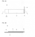
- Figs. 3A-3B schematically show an exemplary configuration of the negative electrode 40.
- the negative electrode 40 which is the negative electrode plate
- the lithium foil is pressure-bonded to the copper foil intermittently, the lithium foil is prone to wrinkles due to a difference in degree of elongation between the lithium foil and the copper foil.
- the lithium foil is pressure-bonded to one front surface of the copper foil and is then bent at a position displaced from the central position in one direction to form a metallic lithium layer on both surfaces of the copper foil and, at the same time, form a portion where the copper foil is exposed.
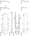
- Figs. 4A-4E show steps of manufacturing an electrode plate 280.
- Fig. 4A shows a first metal foil 200.
- the upper part of Fig. 4A is a top view, and the lower part of Fig. 4A is a side view.
- the first metal foil 200 is a copper foil (about 13 um) which will be the negative electrode current collector 41.
- the first metal foil 200 has a first surface 400 facing upward and a second surface 402 opposite to the first surface 400 and facing downward. In the horizontal direction of the first metal foil 200, a first end 410 is arranged at the left-side edge and a second end 412 is arranged at the right-side edge.
- Fig. 4B shows a step that follows the step of Fig. 4A .
- the upper part of Fig. 4B is a top view, and the lower row of Fig. 4B is a side view.
- a laminated body is formed by stacking the second metal foil 202 on the first surface 400 of the first metal foil 200.
- the second metal foil 202 is a lithium foil (about 10 um) which will be the negative electrode active material layer 42.
- a third end 420 is arranged at the left-side edge and a fourth end 422 is arranged at the right-side edge.
- the width of the second metal foil 202 is larger than the width of the first metal foil 200.
- Fig. 4C shows a step that follows the step of Fig. 4B .
- the upper part of Fig. 4C is a top view, and the lower part of Fig. 4C is a side view.
- a portion of the second metal foil 202 is cut to cause the width of the second metal foil 202 to match the width of the first metal foil 200.
- FIG. 5 is a side view showing a structure of a manufacturing apparatus 180 for the manufacturing in Figs. 4B-4C .
- a first metal foil roll member 100 has the first metal foil 200 wrapped around it.
- a second metal foil roll member 102 has the second metal foil 202 wrapped around it.
- the first metal foil 200 is drawn from the first metal foil roll member 100, and the second metal foil 202 is drawn from the second metal foil roll member 102.
- the first metal foil 200 and the second metal foil 202 travel toward a first pressure bonding roller 110 and a second pressure bonding roller 112 forming a pair of pressure bonding rollers.
- the second metal foil 202 and the first metal foil 200 are stacked from top to bottom in that order.
- the first pressure bonding roller 110 and the second pressure bonding roller 112 are arranged in the vertical direction. To describe it specifically, the first pressure bonding roller 110 is provided on the side of the second metal foil 202, and the second pressure bonding roller 112 is provided on the side of the first metal foil 200.
- the first metal foil 200 and the second metal foil 202 stacked are inserted between the first pressure bonding roller 110 and the second pressure bonding roller 112.
- the first pressure bonding roller 110 and the second pressure bonding roller 112 have a cylindrical shape and are rotatable.
- the first metal foil 200 and the second metal foil 202 are pressure bonded by the rotation of the first pressure bonding roller 110 and the second pressure bonding roller 112.
- a laminated body comprised of the first metal foil 200 and the second metal foil 202 thus pressure bonded is cut as shown in Fig. 4B .
- Fig. 4D shows a step that follows the step of Fig. 4C .
- the upper part of Fig. 4D is a top view, and the lower row of Fig. 4D is a side view.
- the center between the first end 410 and the second end 412 of the first metal foil 200 is indicated as a central position 430. Further, a bending point 440 is arranged between the central position 430 and the second end 412.
- Fig. 4E shows a step that follows Fig. 4D .
- the upper part of Fig. 4E is a top view
- the middle part of Fig. 4E is a bottom view
- the lower part of Fig. 4E is a side view.
- the first metal foil 200 and the second metal foil 202 are bent at the bending point 440 to place the second surface 402 of the first metal foil 200 in contact. That is, the first metal foil 200 and the second metal foil 202 are bent so that the second end 412 and the fourth end 422 are guided downward.
- the second surface 402 of the first metal foil 200 is exposed between the first end 410 and the second end 412.
- the first surface 400 of the first metal foil 200 is not exposed.
- Fig. 4E show the electrode plate 280, which is used, for example, as the negative electrode 40.
- Figs. 6A-6D show the manufacturing steps of Fig. 4E .
- Fig. 6A shows the laminated body of the first metal foil 200 and the second metal foil 202 and the bending point 440 in the laminated body.
- a pin 450 is arranged in the vicinity of the bending point 440. Referring to Fig. 6B , the pin 450 pushes up the bending point 440 as the pin 450 is elevated. Therefore, the laminated body of the first metal foil 200 and the second metal foil 202 is elevated from the bending point 440. Referring to Fig. 6C , the pin 450 returns to its original position. The bending point 440 remains elevated. Referring to Fig. 6D , the laminated body of the first metal foil 200 and the second metal foil 202 is pulled up from the bending point 440.
- embodiment 2 A description will now be given of embodiment 2.
- the first metal foil 200 is exposed through the second metal foil 202 on the side of one surface, and the surface on the opposite side is covered only with the second metal foil 202.
- the surplus portion narrows the space that remains in the battery 10. The description below highlights a difference from embodiment 1.
- Figs. 7A-7E show steps of manufacturing an electrode plate 282.
- Fig. 7A is identical to Fig. 4A .
- Fig. 7B shows a step that follows the step of Fig. 7A .
- the upper part of Fig. 7B is a top view, and the lower part of Fig. 7B is a side view.
- a laminated body is formed by stacking the second metal foil 202 on the first surface 400 of the first metal foil 200. When the first metal foil 200 and the second metal foil 202 are stacked, the second end 412 of the first metal foil 200 and the fourth end 422 of the second metal foil 202 are aligned.
- the third end 420 of the second metal foil 202 is aligned with a position more toward the second end 412 than the first end 410 of the first metal foil. As described above, the width of the second metal foil 202 is larger than the width of the first metal foil 200.
- Fig. 7C shows a step that follows the step of Fig. 7B .
- the upper part of Fig. 7C is a top view, and the lower part of Fig. 7C is a side view.
- a portion of the second metal foil 202 is cut to cause the width of the second metal foil 202 to match the width of the first metal foil 200.
- Figs. 8A-8H show a structure of the laminated body.
- Fig. 8A is a top view of the second metal foil 202 and the first metal foil 200 (not shown) pressure-bonded to each other as viewed from side of the second metal foil 202.
- a first boundary 300 and the second boundary 302 are formed.
- An interval portion 212 is formed between the first boundary 300 and the second boundary 302.
- the foils are pressure bonded.
- the pressure bonding force in the interval portion 212 is weaker than the pressure bonding force in the portions other than the interval portion 212.
- Fig. 8B is a sectional view in A-A' direction of Fig. 8A , i.e., a sectional view of the interval portion 212.
- a weakly pressure bonded portion 220 is provided between the first metal foil 200 and the second metal foil 202.
- the weakly pressure bonded portion 220 is a portion with a weak pressure bonding force.
- a portion of the second metal foil 202 in contact with one end of the first metal foil 200 is a third boundary 304, and a portion in contact with another end of the first metal foil 200 is a fourth boundary 306.
- a portion outside the third boundary 304 is a first surplus portion 210a
- a portion outside the fourth boundary 306 is a second surplus portion 210b.
- the first surplus portion 210a and the second surplus portion 210b are collectively referred to as a surplus portion 210.
- the surplus portion 210 is a portion protruding from the first metal foil 200 and is a portion that does not adhere to the first metal foil 200.
- Fig. 8D is a sectional view in B-B' direction of Fig. 8A .
- the first metal foil 200 and the second metal foil 202 are stacked, and the weakly pressure bonded portion 220 is not provided.
- Fig. 8D is a sectional view in C-C' direction of Fig. 8A .
- the weakly pressure bonded portion 220 is provided only in the interval portion 212, and the weakly pressure bonded portion 220 is not provided in the portions other than the interval portion 212.
- Fig. 8E shows a portion peeled off from the second metal foil 202. As shown, the surplus portion 210 and the interval portion 212 are peeled off.
- Fig. 8F shows the electrode plate 280 which is laminated body that remains when the second metal foil 202 as shown in Fig. 8E has been peeled off. The first metal foil 200 is exposed through a portion of the second metal foil 202.
- Fig. 8G is a D-D' sectional view of Fig. 8F and includes only the first metal foil 200.
- Fig. 8H is an E-E' sectional view of Fig. 8F showing the first metal foil 200 and the second metal foil 202 laminated. The laminated obtained by cutting the plate into a plurality of pieces is shown in Fig. 7C .
- Fig. 7D shows a step that follows the step of Fig. 7C .
- the upper part of Fig. 7D is a top view, and the lower row of Fig. 7D is a side view.
- the center between the first end 410 and the second end 412 of the first metal foil 200 is indicated as the central position 430. Further, the bending point 440 is arranged between the central position 430 and the second end 412.
- Fig. 7E shows a step that follows the step of Fig. 7D .
- the upper part of Fig. 7E is a top view
- the middle part of Fig. 7E is a bottom view
- the lower part of Fig. 7E is a side view.
- the first metal foil 200 and the second metal foil 202 are bent at the bending point 440 to place the second surface 402 of the first metal foil 200 in contact. That is, the first metal foil 200 and the second metal foil 202 are bent so that the second end 412 and the fourth end 422 are guided downward.
- the second surface 402 of the first metal foil 200 is exposed between the first end 410 and the second end 412.
- the first surface 400 of the first metal foil 200 is exposed between the first end 410 and the third end 420.
- Fig. 7E show the electrode plate 282, which is used, for example, as the negative electrode 40.
- the third end 420 of the second metal foil 202 is aligned with a position more toward the second end 412 than the first end 410 of the first metal foil 200 to expose the first metal foil 200 between the first end 410 and the third end 420 so that the electrode plate 282 in which the first metal foil 200 is exposed on both surfaces can be provided.
- the embodiments may be defined by the following items.
Landscapes
- Chemical & Material Sciences (AREA)
- Engineering & Computer Science (AREA)
- Chemical Kinetics & Catalysis (AREA)
- Electrochemistry (AREA)
- General Chemical & Material Sciences (AREA)
- Materials Engineering (AREA)
- Manufacturing & Machinery (AREA)
- Secondary Cells (AREA)
- Battery Electrode And Active Subsutance (AREA)
Abstract
Description
- The present disclosure relates to an electrode plate comprised of two types of metal foils and a method of manufacturing an electrode plate.
- A negative electrode current collector in a secondary battery such as a lithium ion battery is manufactured by arranging a lithium foil as a negative electrode active material on a copper foil that is a current collector. For example, the lithium foil and the copper foil are pressure bonded by guiding them through a pressure bonding roller of a weaker force and a pressure bonding roller of a stronger force (see, for example, Patent Literature 1).
- Patent Literature 1:
JP H3-93156 - In a secondary battery such as a lithium-ion battery, the lithium foil may be pressure bonded to both surfaces of the copper foil. In that case, the foils are prone to wrinkles due to a difference in degree of elongation between the lithium foil and the copper foil.
- The present disclosure addresses the issue described above, and a purpose thereof is to provide an electrode plate that is difficult to wrinkle.
- An electrode plate according to an embodiment of the present disclosure includes: a first metal foil having a first surface and a second surface facing a direction opposite to that of the first surface, a first end and a second being arranged at ends of the first metal foil in one direction; and a second metal foil in which a third end and a fourth end are arranged at ends of the second metal foil in the one direction. The second end of the first metal foil is aligned with the fourth end of the second metal foil, the second metal foil is stacked on the first surface of the first metal foil, a bending point is arranged between i) a central position between the first end and the second end of the first metal foil and ii) the second end, the first metal foil and the second metal foil are bent at the bending point to place the second surface of the first metal foil in contact, and the second surface of the first metal foil is exposed between the first end and the second end.
- Another embodiment of the present disclosure relates to a method of manufacturing an electrode plate. The method includes: forming, given i) a first metal foil having a first surface and a second surface facing a direction opposite to that of the first surface, a first end and a second being arranged at ends of the first metal foil in one direction and ii) a second metal foil in which a third end and a fourth end are arranged at ends of the second metal foil in the one direction, a laminated body in which the second end of the first metal foil is aligned with the fourth end of the second metal foil, and the second metal foil is stacked on the first surface of the first metal foil; and bending, given that a bending point is arranged between i) a central position between the first end and the second end of the first metal foil and ii) the second end, the first metal foil and the second metal foil at the bending point to place the second surface of the first metal foil in contact.
- According to the present disclosure, it is possible to provide an electrode plate that is difficult to wrinkle.
-
- [
Fig. 1] Fig. 1 is a longitudinal sectional view showing a structure of a battery according to embodiment 1. - [
Fig. 2] Fig. 2 is a cross-sectional view showing an exemplary structure of the electrode body ofFig. 1 . - [
Fig. 3] Fig. 3A-3B shows an exemplary configuration of the negative electrode ofFig. 2 . - [
Fig. 4] Figs. 4A-4E show steps of manufacturing an electrode plate according to embodiment 1. - [
Fig. 5] Fig. 5 is a side view showing a structure of a manufacturing apparatus for the manufacturing inFigs. 4B-4C . - [
Fig. 6] Figs. 6A-6D show the manufacturing steps ofFig. 4E . - [
Fig. 7] Figs. 7A-7E show steps of manufacturing an electrode plate according to embodiment 2. - [
Fig. 8] Figs. 8A-8H show a structure of the laminated body ofFig. 7C . - Hereinafter, the present disclosure will be described based on preferred embodiments with reference to drawings. The embodiments do not limit the scope of the present disclosure but exemplify the disclosure. Not all of the features and the combinations thereof described in the embodiments are necessarily essential to the present disclosure. Identical or like constituting elements, members, processes shown in the drawings are represented by identical symbols and a duplicate description will be omitted as appropriate. The scales and shapes of the parts shown in the drawings are defined for convenience sake to make the explanation easy and shall not be interpreted in a limitative manner unless otherwise specified. Terms like "first", "second", etc. used in the specification and claims do not indicate an order or importance by any means unless specified otherwise and are used to distinguish a certain feature from the others. Those of the members that are not material to the description of the embodiments are omitted in the drawings.
- Hereinafter, (1) the structure of a battery and (2) the steps of manufacturing an electrode plate will be described in that order.
- The configuration of a non-aqueous electrolyte secondary battery (hereinafter also referred to as "battery") 10 will be described with reference to
Fig. 1. Fig. 1 is a longitudinal sectional view showing a structure of abattery 10. Thebattery 10 includes a winding-type electrode body 14 in which apositive electrode 30 and anegative electrode 40 are wound in a spiral shape via aseparator 50, a non-aqueous electrolyte (not shown), and a metal battery case (casing body) that accommodates theelectrode body 14 and the non-aqueous electrolyte. A predetermined amount of non-aqueous electrolyte is injected into the battery case and impregnates theelectrode body 14. - The
positive electrode 30 and thenegative electrode 40 have a structure in which an electrode active material layer is stacked on a current collector. For example, the current collector is comprised of an aluminum foil, etc. in the case of a positive electrode and is comprised of a copper foil, etc. in the case of a negative electrode. The electrode active material layer can be formed by applying an electrode mixture material to the surface of the current collector by a known coating apparatus and drying and rolling the material. The electrode mixture material is obtained by kneading materials including an electrode active material, a binder, a conductive material, etc. in a dispersion medium and uniformly dispersing the materials. For example, the electrode active material is lithium cobalt oxide, lithium iron phosphate, etc. in the case of a positive electrode and is graphite, etc. in the case of a negative electrode. - A
case body 15 is, for example, a metal container having a bottomed cylindrical shape. Agasket 27 is provided between thecase body 15 and a sealingbody 16 to ensure sealing inside the battery case. Thecase body 15 preferably has anoverhang 21 formed by, for example, pressing the side portion of thecase body 15 from outside to support the sealingbody 16. - The sealing
body 16 includes afilter 22 in which a filter opening 22a is formed and a valve body arranged on thefilter 22. The valve body blocks the filter opening 22a of thefilter 22 and breaks when the internal pressure of thebattery 10 increases due to heat generation caused by an internal short circuit, etc. In this embodiment, alower valve body 23 and anupper valve body 25 are provided to form a valve body, and aninsulating member 24 arranged between thelower valve body 23 and theupper valve body 25, and acap 26 having a cap opening 26a are further provided. Each member constituting the sealingbody 16 has, for example, a disk shape or a ring shape, and the members except for the insulatingmember 24 are electrically connected to each other. Specifically, thefilter 22 and thelower valve body 23 are joined to each other at their respective peripheral portions, and theupper valve body 25 and thecap 26 are also joined to each other at their respective peripheral portions. Thelower valve body 23 and theupper valve body 25 are connected to each other at the central portions thereof, and theinsulating member 24 is interposed between the peripheral portions thereof. - The
battery 10 includes aninsulating plate 17 and an insulating plate 18 arranged above and below theelectrode body 14, respectively. In the example shown inFig. 1 , apositive electrode lead 19 attached to thepositive electrode 30 extends to the side of the sealingbody 16 via a through hole in theinsulating plate 17. For example, thepositive electrode lead 19 is connected to the lower surface of thefilter 22, which is the bottom plate of the sealingbody 16, by welding, etc., and thecap 26, which is the top plate of the sealingbody 16 electrically connected to thefilter 22, will be a positive electrode terminal. In this embodiment, a current interrupt mechanism (CID) and a gas discharge mechanism (safety valve) are provided in the sealingbody 16. It is preferable to provide a gas discharge valve (not shown) at the bottom of thecase body 15, too. -
Fig. 2 shows a partial cross-sectional view of theelectrode body 14 accommodated in thebattery 10. The belt-likepositive electrode 30 constituting theelectrode body 14 includes a positive electrode current collector 31 (the current collector of the positive electrode), a positive electrode active material layer 32 (the electrode active material layer of the positive electrode) formed on both surfaces of the positive electrodecurrent collector 31, and thepositive electrode lead 19. One end of thepositive electrode lead 19 is bonded to a region where the positive electrodeactive material layer 32 is not formed and the positive electrodecurrent collector 31 is exposed. - The belt-like
negative electrode 40 constituting theelectrode body 14 includes a negative electrode current collector 41 (the current collector of the negative electrode) and a negative electrode active material layer 42 (the active material layer of the negative electrode) formed on the negative electrodecurrent collector 41. As shown inFigs. 1 and2 , thenegative electrode 40 is arranged on the outer circumferential surface of theelectrode body 14 accommodated in the battery case, and the negative electrodecurrent collector 41 is exposed and an exposedportion 43 in contact with the inner circumferential surface of the battery case is provided on the side of the outer circumferential surface of thenegative electrode 40 provided on the outermost circumference.Figs. 3A-3B schematically show an exemplary configuration of thenegative electrode 40.Fig. 3A is a plan view of one principal surface of thenegative electrode 40, andFig. 3B is a sectional view along a line X-X inFig. 3A . As shown inFigs. 3A-3B , thenegative electrode 40 includes the negative electrodecurrent collector 41 and the negative electrodeactive material layer 42 formed on both surfaces of the negative electrodecurrent collector 41. As shown inFigs. 3A and 3B , the exposedportion 43 provided in thenegative electrode 40 is provided on one principal surface of thenegative electrode 40 and at one longitudinal end located in the outermost circumferential portion of theelectrode body 14. - By providing the exposed
portion 43 on the outer circumferential surface of theelectrode body 14 and placing it in contact with the inner circumferential surface of the battery case that also serves as the negative electrode terminal, electrical conduction between thenegative electrode 40 and the battery case is achieved. Since the exposedportion 43 of thenegative electrode 40 is placed in extensive surface contact with the inner peripheral surface of the battery case, the internal resistance of thebattery 10 can be reduced. As a result, a battery with excellent large current discharge characteristics can be realized, and a highly safe battery can be realized because current constriction in the event of an external short circuit can be prevented. - As shown in
Figs. 1 to 3A-3B , a portion in which both surfaces of the negative electrodecurrent collector 41 are exposed is formed in the innermost circumferential portion of thenegative electrode 40, and anegative electrode lead 20 is connected to the portion. Thenegative electrode lead 20 is connected to the inner surface of the bottom of thecase body 15 by welding, etc. By providing thenegative electrode lead 20 apart from the exposedportion 43 connected to the inner circumferential surface of the battery case and connecting thenegative electrode lead 20 to the battery case, the current collection efficiency can be increased and the internal resistance of the battery can be further reduced. Further, dispersion of a short circuit current can suppress local heat generation and prevent an internal short circuit due to separator melting in the event an external short circuit. The position in thenegative electrode 40 in which thenegative electrode lead 20 is provided is not limited to the innermost circumferential portion (the longitudinal end opposite to the exposedportion 43 inFigs. 3A-3B ). Further, it is not necessary to provide thenegative electrode lead 20 in thenegative electrode 40. - Further, as shown in
Figs. 1 to 3A-3B , the negative electrodeactive material layer 42 is formed on the principal surface of thenegative electrode 40 opposite to the exposedportion 43 of the negative electrodecurrent collector 41. This causes the negative electrodeactive material layer 42 to face the positive electrodeactive material layer 32 of thepositive electrode 30, thereby increasing the capacity of the battery. Moreover, the strength of the region of thenegative electrode 40 in which the exposedportion 43 is formed can be maintained, thereby making it easy to accommodate theelectrode body 14 in thecase body 15. - Hereinafter, steps of manufacturing the
negative electrode 40, which is the negative electrode plate, will be described. In thenegative electrode 40, it is necessary to expose the copper foil. When the lithium foil is pressure bonded to the copper foil intermittently, the lithium foil is prone to wrinkles due to a difference in degree of elongation between the lithium foil and the copper foil. In this embodiment, the lithium foil is pressure-bonded to one front surface of the copper foil and is then bent at a position displaced from the central position in one direction to form a metallic lithium layer on both surfaces of the copper foil and, at the same time, form a portion where the copper foil is exposed. -
Figs. 4A-4E show steps of manufacturing anelectrode plate 280.Fig. 4A shows afirst metal foil 200. The upper part ofFig. 4A is a top view, and the lower part ofFig. 4A is a side view. Thefirst metal foil 200 is a copper foil (about 13 um) which will be the negative electrodecurrent collector 41. Thefirst metal foil 200 has afirst surface 400 facing upward and asecond surface 402 opposite to thefirst surface 400 and facing downward. In the horizontal direction of thefirst metal foil 200, afirst end 410 is arranged at the left-side edge and asecond end 412 is arranged at the right-side edge. -
Fig. 4B shows a step that follows the step ofFig. 4A . The upper part ofFig. 4B is a top view, and the lower row ofFig. 4B is a side view. A laminated body is formed by stacking thesecond metal foil 202 on thefirst surface 400 of thefirst metal foil 200. Thesecond metal foil 202 is a lithium foil (about 10 um) which will be the negative electrodeactive material layer 42. In the horizontal direction of thesecond metal foil 202, athird end 420 is arranged at the left-side edge and afourth end 422 is arranged at the right-side edge. When thefirst metal foil 200 and thesecond metal foil 202 are stacked, thesecond end 412 of thefirst metal foil 200 and thefourth end 422 of thesecond metal foil 202 are aligned, and thefirst end 410 of thefirst metal foil 200 and thethird end 420 of thesecond metal foil 202 are also aligned. It will be noted that the width of thesecond metal foil 202 is larger than the width of thefirst metal foil 200. -
Fig. 4C shows a step that follows the step ofFig. 4B . The upper part ofFig. 4C is a top view, and the lower part ofFig. 4C is a side view. As described above, since the width of thesecond metal foil 202 is larger than the width of thefirst metal foil 200, a portion of thesecond metal foil 202 is cut to cause the width of thesecond metal foil 202 to match the width of thefirst metal foil 200. - Hereinafter, manufacturing of the laminated body of
Figs. 4B-4C will be described in more detail.Fig. 5 is a side view showing a structure of amanufacturing apparatus 180 for the manufacturing inFigs. 4B-4C . A first metalfoil roll member 100 has thefirst metal foil 200 wrapped around it. A second metalfoil roll member 102 has thesecond metal foil 202 wrapped around it. - The
first metal foil 200 is drawn from the first metalfoil roll member 100, and thesecond metal foil 202 is drawn from the second metalfoil roll member 102. Thefirst metal foil 200 and thesecond metal foil 202 travel toward a firstpressure bonding roller 110 and a secondpressure bonding roller 112 forming a pair of pressure bonding rollers. In that process, thesecond metal foil 202 and thefirst metal foil 200 are stacked from top to bottom in that order. - The first
pressure bonding roller 110 and the secondpressure bonding roller 112 are arranged in the vertical direction. To describe it specifically, the firstpressure bonding roller 110 is provided on the side of thesecond metal foil 202, and the secondpressure bonding roller 112 is provided on the side of thefirst metal foil 200. Thefirst metal foil 200 and thesecond metal foil 202 stacked are inserted between the firstpressure bonding roller 110 and the secondpressure bonding roller 112. The firstpressure bonding roller 110 and the secondpressure bonding roller 112 have a cylindrical shape and are rotatable. Thefirst metal foil 200 and thesecond metal foil 202 are pressure bonded by the rotation of the firstpressure bonding roller 110 and the secondpressure bonding roller 112. A laminated body comprised of thefirst metal foil 200 and thesecond metal foil 202 thus pressure bonded is cut as shown inFig. 4B . -
Fig. 4D shows a step that follows the step ofFig. 4C . The upper part ofFig. 4D is a top view, and the lower row ofFig. 4D is a side view. The center between thefirst end 410 and thesecond end 412 of thefirst metal foil 200 is indicated as acentral position 430. Further, abending point 440 is arranged between thecentral position 430 and thesecond end 412. -
Fig. 4E shows a step that followsFig. 4D . The upper part ofFig. 4E is a top view, the middle part ofFig. 4E is a bottom view, and the lower part ofFig. 4E is a side view. Thefirst metal foil 200 and thesecond metal foil 202 are bent at thebending point 440 to place thesecond surface 402 of thefirst metal foil 200 in contact. That is, thefirst metal foil 200 and thesecond metal foil 202 are bent so that thesecond end 412 and thefourth end 422 are guided downward. On the lower surface, thesecond surface 402 of thefirst metal foil 200 is exposed between thefirst end 410 and thesecond end 412. On the upper surface, on the other hand, thefirst surface 400 of thefirst metal foil 200 is not exposed.Fig. 4E show theelectrode plate 280, which is used, for example, as thenegative electrode 40. -
Figs. 6A-6D show the manufacturing steps ofFig. 4E .Fig. 6A shows the laminated body of thefirst metal foil 200 and thesecond metal foil 202 and thebending point 440 in the laminated body. Further, apin 450 is arranged in the vicinity of thebending point 440. Referring toFig. 6B , thepin 450 pushes up thebending point 440 as thepin 450 is elevated. Therefore, the laminated body of thefirst metal foil 200 and thesecond metal foil 202 is elevated from thebending point 440. Referring toFig. 6C , thepin 450 returns to its original position. Thebending point 440 remains elevated. Referring toFig. 6D , the laminated body of thefirst metal foil 200 and thesecond metal foil 202 is pulled up from thebending point 440. - According to this embodiment, the
second metal foil 202 is stacked on thefirst surface 400 of thefirst metal foil 200 and then thefirst metal foil 200 and thesecond metal foil 202 are bent at thebending point 440 to place thesecond surface 402 in contact. It is therefore possible to expose thefirst metal foil 200 by a simple configuration. Further, since thefirst metal foil 200 is exposed by a simple configuration, theelectrode plate 280 that is difficult to wrinkle can be provided. Further, since thesecond end 412 of thefirst metal foil 200 and thefourth end 422 of thesecond metal foil 202 are aligned, it is ensured that thefirst metal foil 200 is exposed on the side of one surface, and thefirst metal foil 200 is not exposed on the side of the opposite surface. Further, the exposed area of thefirst metal foil 200 can be adjusted by adjusting the position of thebending point 440. Further, since the exposed area of thefirst metal foil 200 is adjusted, design changes can be made easily. - A description will now be given of embodiment 2. In the
electrode plate 280 according to embodiment 1, thefirst metal foil 200 is exposed through thesecond metal foil 202 on the side of one surface, and the surface on the opposite side is covered only with thesecond metal foil 202. When thesecond metal foil 202 contains a surplus portion, the surplus portion narrows the space that remains in thebattery 10. The description below highlights a difference from embodiment 1. -
Figs. 7A-7E show steps of manufacturing anelectrode plate 282.Fig. 7A is identical toFig. 4A .Fig. 7B shows a step that follows the step ofFig. 7A . The upper part ofFig. 7B is a top view, and the lower part ofFig. 7B is a side view. A laminated body is formed by stacking thesecond metal foil 202 on thefirst surface 400 of thefirst metal foil 200. When thefirst metal foil 200 and thesecond metal foil 202 are stacked, thesecond end 412 of thefirst metal foil 200 and thefourth end 422 of thesecond metal foil 202 are aligned. Further, thethird end 420 of thesecond metal foil 202 is aligned with a position more toward thesecond end 412 than thefirst end 410 of the first metal foil. As described above, the width of thesecond metal foil 202 is larger than the width of thefirst metal foil 200. -
Fig. 7C shows a step that follows the step ofFig. 7B . The upper part ofFig. 7C is a top view, and the lower part ofFig. 7C is a side view. As described above, since the width of thesecond metal foil 202 is larger than the width of thefirst metal foil 200, a portion of thesecond metal foil 202 is cut to cause the width of thesecond metal foil 202 to match the width of thefirst metal foil 200. -
Figs. 8A-8H show a structure of the laminated body.Fig. 8A is a top view of thesecond metal foil 202 and the first metal foil 200 (not shown) pressure-bonded to each other as viewed from side of thesecond metal foil 202. Afirst boundary 300 and thesecond boundary 302 are formed. - An
interval portion 212 is formed between thefirst boundary 300 and thesecond boundary 302. In the other portions, on the other hand, the foils are pressure bonded. The pressure bonding force in theinterval portion 212 is weaker than the pressure bonding force in the portions other than theinterval portion 212. -
Fig. 8B is a sectional view in A-A' direction ofFig. 8A , i.e., a sectional view of theinterval portion 212. A weakly pressure bondedportion 220 is provided between thefirst metal foil 200 and thesecond metal foil 202. The weakly pressure bondedportion 220 is a portion with a weak pressure bonding force. - As shown in
Fig. 8A , a portion of thesecond metal foil 202 in contact with one end of thefirst metal foil 200 is athird boundary 304, and a portion in contact with another end of thefirst metal foil 200 is afourth boundary 306. A portion outside thethird boundary 304 is afirst surplus portion 210a, and a portion outside thefourth boundary 306 is asecond surplus portion 210b. Thefirst surplus portion 210a and thesecond surplus portion 210b are collectively referred to as a surplus portion 210. The surplus portion 210 is a portion protruding from thefirst metal foil 200 and is a portion that does not adhere to thefirst metal foil 200. -
Fig. 8D is a sectional view in B-B' direction ofFig. 8A . Thefirst metal foil 200 and thesecond metal foil 202 are stacked, and the weakly pressure bondedportion 220 is not provided.Fig. 8D is a sectional view in C-C' direction ofFig. 8A . As described above, the weakly pressure bondedportion 220 is provided only in theinterval portion 212, and the weakly pressure bondedportion 220 is not provided in the portions other than theinterval portion 212. -
Fig. 8E shows a portion peeled off from thesecond metal foil 202. As shown, the surplus portion 210 and theinterval portion 212 are peeled off.Fig. 8F shows theelectrode plate 280 which is laminated body that remains when thesecond metal foil 202 as shown inFig. 8E has been peeled off. Thefirst metal foil 200 is exposed through a portion of thesecond metal foil 202.Fig. 8G is a D-D' sectional view ofFig. 8F and includes only thefirst metal foil 200.Fig. 8H is an E-E' sectional view ofFig. 8F showing thefirst metal foil 200 and thesecond metal foil 202 laminated. The laminated obtained by cutting the plate into a plurality of pieces is shown inFig. 7C . -
Fig. 7D shows a step that follows the step ofFig. 7C . The upper part ofFig. 7D is a top view, and the lower row ofFig. 7D is a side view. The center between thefirst end 410 and thesecond end 412 of thefirst metal foil 200 is indicated as thecentral position 430. Further, thebending point 440 is arranged between thecentral position 430 and thesecond end 412. -
Fig. 7E shows a step that follows the step ofFig. 7D . The upper part ofFig. 7E is a top view, the middle part ofFig. 7E is a bottom view, and the lower part ofFig. 7E is a side view. Thefirst metal foil 200 and thesecond metal foil 202 are bent at thebending point 440 to place thesecond surface 402 of thefirst metal foil 200 in contact. That is, thefirst metal foil 200 and thesecond metal foil 202 are bent so that thesecond end 412 and thefourth end 422 are guided downward. On the lower surface, thesecond surface 402 of thefirst metal foil 200 is exposed between thefirst end 410 and thesecond end 412. Further, on the upper surface, thefirst surface 400 of thefirst metal foil 200 is exposed between thefirst end 410 and thethird end 420.Fig. 7E show theelectrode plate 282, which is used, for example, as thenegative electrode 40. - According to this embodiment, the
third end 420 of thesecond metal foil 202 is aligned with a position more toward thesecond end 412 than thefirst end 410 of thefirst metal foil 200 to expose thefirst metal foil 200 between thefirst end 410 and thethird end 420 so that theelectrode plate 282 in which thefirst metal foil 200 is exposed on both surfaces can be provided. - The embodiments of the present disclosure are described above in detail. The embodiments described above are merely specific examples of practicing the present disclosure. The details of the embodiments shall not be construed as limiting the technical scope of the present disclosure. A number of design modifications such as modification, addition, deletion, etc. of constituting elements may be made to the extent that they do not depart from the idea of the present disclosure defined by the claims. New embodiments with design modifications will provide the combined advantages of the embodiment and the variation. Although the details subject to such design modification are emphasized in the embodiment described above by using phrases such as "of this embodiment" and "in this embodiment", details not referred to as such are also subject to design modification. Any combination of constituting elements included in the respective embodiments is also useful as an embodiment of the present disclosure. Hatching in the section in the drawings should not be construed as limiting the material of the hatched object.
- The embodiments may be defined by the following items.
- An electrode plate (280, 282) including:
- a first metal foil (200) having a first surface (400) and a second surface (402) facing a direction opposite to that of the first surface (400), a first end (410) and a second (412) being arranged at ends of the first metal foil (200) in one direction; and
- a second metal foil (202) in which a third end (420) and a fourth end (422) are arranged at ends of the second metal foil (202) in the one direction,
- wherein the second end (412) of the first metal foil (200) is aligned with the fourth end (422) of the second metal foil (202), and the second metal foil (202) is stacked on the first surface (400) of the first metal foil (200),
- wherein a bending point (440) is arranged between i) a central position (430) between the first end (410) and the second end (412) of the first metal foil (200) and ii) the second end (412), and the first metal foil (200) and the second metal foil (202) are bent at the bending point (440) to place the second surface (402) of the first metal foil (200) in contact, and
- wherein the second surface (402) of the first metal foil (200) is exposed between the first end (410) and the second end (412).
- The electrode plate (280) according to Item 1,
- wherein the first end (410) of the first metal foil (200) and the third end (420) of the second metal foil (202) are aligned, and the second metal foil (202) is stacked on the first surface (400) of the first metal foil (200), and
- wherein the first surface (400) of the first metal foil (200) is not exposed.
- The electrode plate (282) according to Item 1,
- wherein the third end (420) of the second metal foil (202) is aligned with a position more toward the second end (412) than the first end (410) of the first metal foil (200), and the second metal foil (202) is stacked on the first surface (400) of the first metal foil (200), and
- wherein the first surface (400) of the first metal foil (200) is exposed between the first end (410) and the third end (420).
- A method of manufacturing an electrode plate (280, 282), including:
- forming, given i) a first metal foil (200) having a first surface (400) and a second surface (402) facing a direction opposite to that of the first surface (400), a first end (410) and a second (412) being arranged at ends of the first metal foil (200) in one direction and ii) a second metal foil (202) in which a third end (420) and a fourth end (422) are arranged at ends of the second metal foil (202) in the one direction, a laminated body in which the second end (412) of the first metal foil (200) is aligned with the fourth end (422) of the second metal foil (202), and the second metal foil (202) is stacked on the first surface (400) of the first metal foil (200); and
- bending, given that a bending point (440) is arranged between i) a central position (430) between the first end (410) and the second end (412) of the first metal foil (200) and ii) the second end (412), the first metal foil (200) and the second metal foil (202) at the bending point (440) to place the second surface (402) of the first metal foil (200) in contact.
- The method of manufacturing an electrode plate (280) according to Item 4,
wherein, in the forming of the laminated body, the first end (410) of the first metal foil (200) and the third end (420) of the second metal foil (202) are aligned, and the second metal foil (202) is stacked on the first surface (400) of the first metal foil (200). - The method of manufacturing an electrode plate (280) according to Item 4,
wherein, in the forming of the laminated body, the third end (420) of the second metal foil (202) is aligned with a position more toward the second end (412) than the first end (410) of the first metal foil (200), and the second metal foil (202) is stacked on the first surface (400) of the first metal foil (200). - According to the present disclosure, it is possible to provide an electrode plate that is difficult to wrinkle.
- 10 battery, 14 electrode body, 15 case body, 16 sealing body, 17, 18, insulating plate, 19 positive electrode lead, 20 negative electrode lead, 21 overhang, 22a filter opening, 22 filter, 23 lower valve body, 24 insulating member, 25 upper valve body, 26a cap opening, 27 gasket, 30 positive electrode, 21 positive electrode current collector, 32 positive electrode active material layer, 40 negative electrode, 41 negative electrode current collector, 42 negative electrode active material layer, 43 exposed portion, 50 separator, 100 first metal foil roll member, 102 second metal foil roll member, 110 first pressure bonding roller, 112 second pressure bonding layer, 180 manufacturing apparatus, 200 first metal foil, 202 second metal foil, 210 surplus portion, 212 interval portion, 220 weakly pressure bonded portion, 280, 282 electrode plate, 300 first boundary, 302 second boundary, 304 third boundary, 306 fourth boundary, 400 first surface, 402 second surface, 410 first end, 412 second end, 420 third end, 422 fourth end, 430 central position, 440 bending point, 450 pin
Claims (6)
- An electrode plate comprising:a first metal foil having a first surface and a second surface facing a direction opposite to that of the first surface, a first end and a second being arranged at ends of the first metal foil in one direction; anda second metal foil in which a third end and a fourth end are arranged at ends of the second metal foil in the one direction,wherein the second end of the first metal foil is aligned with the fourth end of the second metal foil, and the second metal foil is stacked on the first surface of the first metal foil,wherein a bending point is arranged between i) a central position between the first end and the second end of the first metal foil and ii) the second end, and the first metal foil and the second metal foil are bent at the bending point to place the second surface of the first metal foil in contact, andwherein the second surface of the first metal foil is exposed between the first end and the second end.
- The electrode plate according to Claim 1,wherein the first end of the first metal foil and the third end of the second metal foil are aligned, and the second metal foil is stacked on the first surface of the first metal foil, andwherein the first surface of the first metal foil is not exposed.
- The electrode plate according to Claim 1,wherein the third end of the second metal foil is aligned with a position more toward the second end than the first end of the first metal foil, and the second metal foil is stacked on the first surface of the first metal foil, andwherein the first surface of the first metal foil is exposed between the first end and the third end.
- A method of manufacturing an electrode plate, comprising:forming, given i) a first metal foil having a first surface and a second surface facing a direction opposite to that of the first surface, a first end and a second being arranged at ends of the first metal foil in one direction and ii) a second metal foil in which a third end and a fourth end are arranged at ends of the second metal foil in the one direction, a laminated body in which the second end of the first metal foil is aligned with the fourth end of the second metal foil, and the second metal foil is stacked on the first surface of the first metal foil; andbending, given that a bending point is arranged between i) a central position between the first end and the second end of the first metal foil and ii) the second end, the first metal foil and the second metal foil at the bending point to place the second surface of the first metal foil in contact.
- The method of manufacturing an electrode plate according to Claim 4,
wherein, in the forming of the laminated body, the first end of the first metal foil and the third end of the second metal foil are aligned, and the second metal foil is stacked on the first surface of the first metal foil. - The method of manufacturing an electrode plate according to Claim 4,
wherein, in the forming of the laminated body, the third end of the second metal foil is aligned with a position more toward the second end than the first end of the first metal foil, and the second metal foil is stacked on the first surface of the first metal foil.
Applications Claiming Priority (2)
| Application Number | Priority Date | Filing Date | Title |
|---|---|---|---|
| JP2022051545 | 2022-03-28 | ||
| PCT/JP2023/011582 WO2023190057A1 (en) | 2022-03-28 | 2023-03-23 | Electrode plate and electrode plate manufacturing method |
Publications (2)
| Publication Number | Publication Date |
|---|---|
| EP4503154A1 true EP4503154A1 (en) | 2025-02-05 |
| EP4503154A4 EP4503154A4 (en) | 2026-01-07 |
Family
ID=88202074
Family Applications (1)
| Application Number | Title | Priority Date | Filing Date |
|---|---|---|---|
| EP23780067.7A Pending EP4503154A4 (en) | 2022-03-28 | 2023-03-23 | ELECTRODE BOARD AND ELECTRODE BOARD MANUFACTURING PROCESS |
Country Status (5)
| Country | Link |
|---|---|
| US (1) | US20250219046A1 (en) |
| EP (1) | EP4503154A4 (en) |
| JP (1) | JPWO2023190057A1 (en) |
| CN (1) | CN118901148A (en) |
| WO (1) | WO2023190057A1 (en) |
Family Cites Families (6)
| Publication number | Priority date | Publication date | Assignee | Title |
|---|---|---|---|---|
| JPS5545154U (en) * | 1978-09-20 | 1980-03-24 | ||
| US10629947B2 (en) * | 2008-08-05 | 2020-04-21 | Sion Power Corporation | Electrochemical cell |
| JP4984553B2 (en) * | 2006-01-30 | 2012-07-25 | ソニー株式会社 | Secondary battery negative electrode and secondary battery using the same |
| US20110311854A1 (en) * | 2007-01-03 | 2011-12-22 | Greatbatch Ltd. | Electrochemical Cell Electrode With Sandwich Cathode And Method For Making Same |
| JP2009224102A (en) * | 2008-03-14 | 2009-10-01 | Hitachi Maxell Ltd | Flat battery |
| WO2012027457A2 (en) * | 2010-08-24 | 2012-03-01 | Sion Power Corporation | Electrically non-conductive materials for electrochemical cells |
-
2023
- 2023-03-23 JP JP2024512283A patent/JPWO2023190057A1/ja active Pending
- 2023-03-23 CN CN202380027857.XA patent/CN118901148A/en active Pending
- 2023-03-23 WO PCT/JP2023/011582 patent/WO2023190057A1/en not_active Ceased
- 2023-03-23 EP EP23780067.7A patent/EP4503154A4/en active Pending
- 2023-03-23 US US18/850,858 patent/US20250219046A1/en active Pending
Also Published As
| Publication number | Publication date |
|---|---|
| US20250219046A1 (en) | 2025-07-03 |
| JPWO2023190057A1 (en) | 2023-10-05 |
| EP4503154A4 (en) | 2026-01-07 |
| WO2023190057A1 (en) | 2023-10-05 |
| CN118901148A (en) | 2024-11-05 |
Similar Documents
| Publication | Publication Date | Title |
|---|---|---|
| EP3490033B1 (en) | Electrode member, electrode assembly and rechargeable battery | |
| EP3477729B2 (en) | Rechargeable lithium ion button cell battery | |
| US11799158B2 (en) | Top plate for laser welded lithium-ion button cell battery | |
| EP3907819B1 (en) | Secondary battery | |
| CN205319258U (en) | Round lithium ion battery | |
| CN209401755U (en) | Electrode assembly, secondary battery and battery module | |
| US11043677B2 (en) | Secondary battery and electrode member thereof having an electricity generation region with reduced curvature | |
| EP4597656A1 (en) | Cylindrical secondary battery | |
| KR102226916B1 (en) | Cylindrical Secondary Battery Having Protrusion of Improved Weld-ability | |
| JP2005332820A (en) | Secondary battery having electrode assembly | |
| CN115966852B (en) | Battery | |
| CN218005146U (en) | Battery, battery pack comprising same and automobile | |
| TW202220278A (en) | Electrochemical cell with contact lug | |
| US7488556B2 (en) | Battery module and its method of manufacture | |
| KR100599713B1 (en) | Secondary Battery and Electrode Assembly Used in the Same | |
| EP4503154A1 (en) | Electrode plate and electrode plate manufacturing method | |
| KR20080016047A (en) | Secondary battery | |
| EP4496019A1 (en) | Manufacturing apparatus | |
| US12469904B2 (en) | Flat secondary battery | |
| EP4120382A1 (en) | Connection lead and battery | |
| CN116998059A (en) | Cylindrical secondary battery | |
| CN204391187U (en) | Battery insulation board and there is the battery of this insulation board | |
| JP3558328B2 (en) | Non-aqueous electrolyte secondary battery and method of manufacturing the same | |
| CN220172250U (en) | Top cover structure and battery | |
| KR102929637B1 (en) | Secondary battery |
Legal Events
| Date | Code | Title | Description |
|---|---|---|---|
| STAA | Information on the status of an ep patent application or granted ep patent |
Free format text: STATUS: THE INTERNATIONAL PUBLICATION HAS BEEN MADE |
|
| PUAI | Public reference made under article 153(3) epc to a published international application that has entered the european phase |
Free format text: ORIGINAL CODE: 0009012 |
|
| STAA | Information on the status of an ep patent application or granted ep patent |
Free format text: STATUS: REQUEST FOR EXAMINATION WAS MADE |
|
| 17P | Request for examination filed |
Effective date: 20241018 |
|
| AK | Designated contracting states |
Kind code of ref document: A1 Designated state(s): AL AT BE BG CH CY CZ DE DK EE ES FI FR GB GR HR HU IE IS IT LI LT LU LV MC ME MK MT NL NO PL PT RO RS SE SI SK SM TR |
|
| DAV | Request for validation of the european patent (deleted) | ||
| DAX | Request for extension of the european patent (deleted) | ||
| REG | Reference to a national code |
Ref country code: DE Ref legal event code: R079 Free format text: PREVIOUS MAIN CLASS: H01M0004020000 Ipc: H01M0004040000 |
|
| A4 | Supplementary search report drawn up and despatched |
Effective date: 20251204 |
|
| RIC1 | Information provided on ipc code assigned before grant |
Ipc: H01M 4/04 20060101AFI20251128BHEP Ipc: H01M 4/134 20100101ALI20251128BHEP Ipc: H01M 4/1395 20100101ALI20251128BHEP Ipc: H01M 4/66 20060101ALI20251128BHEP Ipc: H01M 4/38 20060101ALN20251128BHEP |