EP4503076A1 - Linear drive for a circuit breaker - Google Patents
Linear drive for a circuit breaker Download PDFInfo
- Publication number
- EP4503076A1 EP4503076A1 EP23189678.8A EP23189678A EP4503076A1 EP 4503076 A1 EP4503076 A1 EP 4503076A1 EP 23189678 A EP23189678 A EP 23189678A EP 4503076 A1 EP4503076 A1 EP 4503076A1
- Authority
- EP
- European Patent Office
- Prior art keywords
- coil
- plunger
- connection rod
- axis
- distance
- Prior art date
- Legal status (The legal status is an assumption and is not a legal conclusion. Google has not performed a legal analysis and makes no representation as to the accuracy of the status listed.)
- Pending
Links
Images




Classifications
-
- H—ELECTRICITY
- H01—ELECTRIC ELEMENTS
- H01H—ELECTRIC SWITCHES; RELAYS; SELECTORS; EMERGENCY PROTECTIVE DEVICES
- H01H3/00—Mechanisms for operating contacts
- H01H3/22—Power arrangements internal to the switch for operating the driving mechanism
- H01H3/28—Power arrangements internal to the switch for operating the driving mechanism using electromagnet
-
- H—ELECTRICITY
- H01—ELECTRIC ELEMENTS
- H01H—ELECTRIC SWITCHES; RELAYS; SELECTORS; EMERGENCY PROTECTIVE DEVICES
- H01H33/00—High-tension or heavy-current switches with arc-extinguishing or arc-preventing means
- H01H33/02—Details
- H01H33/28—Power arrangements internal to the switch for operating the driving mechanism
- H01H33/38—Power arrangements internal to the switch for operating the driving mechanism using electromagnet
-
- H—ELECTRICITY
- H01—ELECTRIC ELEMENTS
- H01H—ELECTRIC SWITCHES; RELAYS; SELECTORS; EMERGENCY PROTECTIVE DEVICES
- H01H33/00—High-tension or heavy-current switches with arc-extinguishing or arc-preventing means
- H01H33/60—Switches wherein the means for extinguishing or preventing the arc do not include separate means for obtaining or increasing flow of arc-extinguishing fluid
- H01H33/66—Vacuum switches
- H01H33/666—Operating arrangements
- H01H33/6662—Operating arrangements using bistable electromagnetic actuators, e.g. linear polarised electromagnetic actuators
-
- H—ELECTRICITY
- H01—ELECTRIC ELEMENTS
- H01H—ELECTRIC SWITCHES; RELAYS; SELECTORS; EMERGENCY PROTECTIVE DEVICES
- H01H51/00—Electromagnetic relays
- H01H51/02—Non-polarised relays
- H01H51/20—Non-polarised relays with two or more independent armatures
Definitions
- the present invention relates to linear drives for a circuit breaker.
- Today's circuit breakers are equipped with drives to provide the opening- and closing-operation to get the electrical network connected and disconnected.
- the circuit breaker operation for example a vacuum interrupter operation, takes place by a linear movement in the range from 10 to 25mm to provide enough contact distance to allow the making and breaking operation under no load and under voltage and load current conditions.
- Mainly these drives are equipped with mechanical spring driven drives to enable long term storage (30 or more years) of energy as potential energy in charged spring(s).
- a linear drive for a circuit breaker comprising:
- connection rod is configured to connect to a movable contact of a circuit breaker.
- first coil is adjacent to the first plunger and on an opposite side of the first plunger to the second coil
- first plunger is between the first coil and the second coil
- second plunger is adjacent to the second coil and on an opposite side of the second coil to the first plunger.
- the coils are used to push the plungers away from them.
- the second plunger is fixedly connected to the connection rod.
- connection rod comprises a flange.
- the flange is fixedly connected to the connection rod or the flange is a part of the rod.
- first plunger moves away from the first coil along the axis of the connection rod in the first direction the first plunger is configured to engage with the flange to move the connection rod in the first direction in the first direction by the first distance.
- the first coil is at a fixed location within the drive.
- the second coil is at a fixed location within the drive.
- the drive is configured to activate the first coil and the second coil simultaneously.
- the drive is configured to activate the first coil and then activate the second coil.
- the drive is configured to activate the second coil after activation of the first coil has moved the first plunger away from the first coil along the axis of the connection rod in the first direction by the first distance.
- the drive is configured to activate the second coil and then activate the first coil.
- the drive is configured to activate the first coil after activation of the second coil has moved the second plunger away from the second coil along the axis of the connection rod in the first direction by the second distance.
- the drive comprises a spring.
- the spring is configured to move the connection rod along the axis of the connection rod in a second direction opposite to the first direction by a distance equal to the first distance added to the second distance.
- the spring is used to bring the drive back to the start position, and moves the plungers in an opposite direction to the movement provided by the coils.
- a linear drive for a circuit breaker comprising:
- connection rod is configured to connect to a movable contact of a circuit breaker.
- first coil is adjacent to the first plunger and on an opposite side of the first plunger to the second coil
- first plunger is between the first coil and the second coil
- second plunger is adjacent to the second coil and on an opposite side of the second coil to the first plunger.
- the coils are used to pull the plungers towards them.
- the second plunger is fixedly connected to the connection rod.
- connection rod comprises a flange.
- the flange is fixedly connected to the connection rod or the flange is a part of the rod, and wherein when the first plunger moves toward the first coil along the axis of the connection rod in the first direction the first plunger is configured to engage with the flange to move the connection rod in the first direction in the first direction by the first distance.
- a linear drive for a circuit breaker comprising:
- connection rod is configured to connect to a movable contact of a circuit breaker.
- the first coil is adjacent to the first plunger and on an opposite side of the first plunger to the second coil
- the first plunger is between the first coil and the second coil
- the second plunger is adjacent to the second coil and on an opposite side of the second coil to the first plunger.
- the coils in a first mode of operation the coils push the plungers away from them, and in a second mode of operation the coils pull the plungers towards them.
- the new developments relate to linear drives for circuit breakers, as shown in specific examples of Figs. 1-9 , and 10a-10b .
- the drive can be a three stage, four stage or N stage drive, with three coils and three plungers, four coils and four plungers, or N coils and N plungers.
- the movement of the travel can be adjusted by energizing the coils or generating eddy current within a magnetic flux circuit to deaccelerate the drive mechanism.
- the coil(s) will be energized like a Thomson coil the velocity can be even faster.
- the drive will be comparable faster in case all coils are perfectly energized, all gaps to be closed are lower and active like linear motor rail, linear motor device.
- a linear drive for a circuit breaker comprises:
- connection rod is configured to connect to a movable contact of a circuit breaker.
- the first coil is adjacent to the first plunger and on an opposite side of the first plunger to the second coil
- the first plunger is between the first coil and the second coil
- the second plunger is adjacent to the second coil and on an opposite side of the second coil to the first plunger.
- connection rod has been moved by a distance equal to the first distance, provided by a first stage of the drive, plus the second distance, provided by a second stage of the drive, but the first stage has only required to move components by the first distance and the second stage only required to move components by the second distance.
- first coil 30 and the first plunger 40 are part of a first stage and the second coil 100 and the second plunger are part of a second stage, and the coil of the first stage activates to move the first plunger that moves the connection rod and the second plunger axially and the coil of the second stage activates to move the second plunger that continues to move the connection rod axially.
- the overall movement of the connection rod is then provided by a movement from the second stage added to a movement of the first stage.
- the coils can operate consecutively, or in an overlapped manner, and the temporal profile of the movement of the movable contact (the travel curve) can be controlled as required.
- the linear drive can be used to make linear movements of the connection rod of up to 60mm and more. This can be achieved through example by having more stages than the two described above, where there can be a whole series of coils and plungers operating in relay, closing multiple gaps cumulatively to provide a very large overall gap movement.
- the second plunger is fixedly connected to the connection rod.
- connection rod comprises a flange 90.
- the flange is fixedly connected to the connection rod or the flange is a part of the rod.
- first plunger moves away from the first coil along the axis of the connection rod in the first direction the first plunger is configured to engage with the flange to move the connection rod in the first direction in the first direction by the first distance.
- the first coil is at a fixed location within the drive.
- the second coil is at a fixed location within the drive.
- the drive is configured to activate the first coil and then activate the second coil.
- the drive is configured to activate the second coil and then activate the first coil.
- the drive is configured to activate the first coil after activation of the second coil has moved the second plunger away from the second coil along the axis of the connection rod in the first direction by the second distance.
- the drive comprises a spring 10.
- the spring In a second mode of operation the spring is configured to move the connection rod along the axis of the connection rod in a second direction opposite to the first direction by a distance equal to the first distance added to the second distance.
- the coils act in a first mode to push the plungers away from them, and in a second mode the spring can bring the drive back to a start position.
- the coils 30 and 100 with the associated plungers 40 and 80 are used to move the connection rod, for example to an open position.
- the spring can for example have energy stored in it.
- the drive can then be held or latched in position, however when the latch is released the spring 10 supports the open operation.
- connection rod is configured to connect to a movable contact of a circuit breaker.
- the first coil is adjacent to the first plunger and on an opposite side of the first plunger to the second coil
- the first plunger is between the first coil and the second coil
- the second plunger is adjacent to the second coil and on an opposite side of the second coil to the first plunger.
- connection rod has been moved by a distance equal to the first distance, provided by a first stage of the drive, plus the second distance, provided by a second stage of the drive, but the first stage has only required to move components by the first distance and the second stage only required to move components by the second distance.
- first coil 30 and the first plunger 40 are part of a first stage and the second coil 100 and the second plunger are part of a second stage, and the coil of the first stage activates to move the first plunger that moves the connection rod and the second plunger axially and the coil of the second stage activates to move the second plunger that continues to move the connection rod axially.
- the overall movement of the connection rod is then provided by a movement from the second stage added to a movement of the first stage.
- the drive is working in an opposite sense to the previously described drive, where rather than pushing plungers by coils, the coils are pulling plungers towards them.
- the second plunger is fixedly connected to the connection rod.
- connection rod comprises a flange 110.
- the flange is fixedly connected to the connection rod or the flange is a part of the connection rod.
- first plunger moves toward the first coil along the axis of the connection rod in the first direction the first plunger is configured to engage with the flange to move the connection rod in the first direction in the first direction by the first distance.
- the first coil is at a fixed location within the drive.
- the drive is configured to activate the first coil and the second coil simultaneously.
- the drive is configured to activate the first coil and then activate the second coil.
- the drive is configured to activate the second coil after activation of the first coil has moved the first plunger toward the first coil along the axis of the connection rod in the first direction by the first distance.
- the drive is configured to activate the second coil and then activate the first coil.
- the drive is configured to activate the first coil after activation of the second coil has moved the second plunger toward the second coil along the axis of the connection rod in the first direction by the second distance.
- the drive comprises a spring 10.
- the spring In a second mode of operation the spring is configured to move the connection rod along the axis of the connection rod in a second direction opposite to the first direction by a distance equal to the first distance added to the second distance.
- a linear drive for a circuit breaker comprises:
- connection rod is configured to connect to a movable contact of a circuit breaker.
- the first coil is adjacent to the first plunger and on an opposite side of the first plunger to the second coil, the first plunger is between the first coil and the second coil, and the second plunger is adjacent to the second coil and on an opposite side of the second coil to the first plunger;
- this example of drive can be considered to be a combination of parts of the above two drives combined together.
- the coils and plungers are used to move the connection rod in both directions.
- the second plunger is fixedly connected to the connection rod.
- the description for ease or explanation, relates to a two-stage drive, with two sets of coils and two plungers.
- the drive can be a multi-stage drive, with three or more sets of coils and three or more associated plungers. When there are numerous coils/plunger, then the last plunger is fixedly connected to the connection rod.
- connection rod comprises a first flange 90.
- the first flange is fixedly connected to the connection rod or the first flange is a part of the connection rod.
- first plunger moves away from the first coil along the axis of the connection rod in the first direction the first plunger is configured to engage with the first flange to move the connection rod in the first direction in the first direction by the first distance.
- the first coil is at a fixed location within the drive.
- the second coil is at a fixed location within the drive.
- the drive in the first mode of operation is configured to activate the first coil and the second coil simultaneously.
- the drive in the first mode of operation is configured to activate the first coil and then activate the second coil.
- the drive in the first mode of operation is configured to activate the second coil and then activate the first coil.
- the drive in the first mode of operation is configured to activate the first coil after activation of the second coil has moved the second plunger away from the second coil along the axis of the connection rod in the first direction by the second distance.
- connection rod comprises a second flange 110.
- the second flange is fixedly connected to the connection rod or the second flange is a part of the rod.
- first plunger moves toward the first coil along the axis of the connection rod in the second direction the first plunger is configured to engage with the second flange to move the connection rod in the second direction by the first distance.
- the drive in the second mode of operation is configured to activate the first coil and the second coil simultaneously.
- the drive in the second mode of operation is configured to activate the first coil and then activate the second coil.
- the drive in the second mode of operation is configured to activate the second coil after activation of the first coil has moved the first plunger toward the first coil along the axis of the connection rod in the first direction by the first distance.
- the drive in the second mode of operation is configured to activate the second coil and then activate the first coil.
- the drive in the second mode of operation is configured to activate the first coil after activation of the second coil has moved the second plunger toward the second coil along the axis of the connection rod in the first direction by the second distance.
- the inventor's started from the existing position, where a circuit breaker needs a one gap to be closed or opened in a single stroke, which has associated limitations.
- the new development for the new linear drives is to provide a drive that has divided the closing of a single big gap in one step into closing a gap into several smaller steps. Having smaller gaps to be closed provides for better magnetic flux through each open “smaller” gap and increases the magnetic force to close the "smaller” gap and hence the overall gap.
- the movable side of the new drive is directly connected to the main (connection) rod to the interruption device - the circuit breaker.
- the new development is to move the main rod by using some smaller gaps in the multistage electromagnetic device like a linear motor. That means in the new technique, the main connection rod is moved by in effect drive plates (plungers) which are closing in a row and drive the main rod of drive by a gap distance that is a sum of the smaller gap closures.
- the first gap will be close quite fast and precisely from the timing perspective.
- the first stage will close and accelerate the mass of the movable parts.
- the second, or all further steps, can then close after each other and so the drive will close completely and the needed energy for the complete device operation will be reduced.
- each gap to be closed is smaller than a single a "huge" gap that must be overcome in case of existing one step electromechanical drive. It is to be noted, that this description has all stages closing one after the other, but all stages can close simultaneously if required.
- the coils and plungers of each stage can be used to close gaps and move a connection rod in one direction and can also open gaps to move the connection rod in the opposite direction.
- the coils and plungers of each stage can be used to close gaps and move the connection rod in one direction and a spring 10 can be used to move the connection rod in the opposite, or the coils and plungers of each stage can be used to open gaps and move the connection rod in one direction and a spring can be used to move the connection rod in the opposite.
- Fig. 1 shows an embodiment of the new drive.
- the drive On the left the drive is in the open configuration.
- Plunger 40 is attracted towards and moves towards coils 30 and engages with rand board/flange 110 that is fixed to connection rod 20 that moves the connection rod upwards.
- the plunger 80 is also connected to the connection rod 20 and is also move upwards. This can be seen in the transition from the open configuration to the semi closed configuration.
- a second stage of closing is made, where plunger 80 is attracted towards and moves towards coils 100. This continues to move the connection rod upwards until an overall closure movement has been made that is greater than the individual closing movements.
- Figs. 2 and 3 show an embodiment of the new drive, with Fig. 2 showing the drive in a closed configuration for a circuit breaker when closed, where both plungers are in the closed position adjacent to the associated coils, with Fig, 3 showing the drive in an open configuration for the circuit breaker when open, where both plungers are in the open position spaced from the associated coils.
- Figs. 4 and 5 show an embodiment of the new drive, with Fig. 4 showing the drive in a closed configuration for a circuit breaker when closed. where both plungers are in the closed position adjacent to the associated coils, with Fig, 5 showing the drive in an open configuration for the circuit breaker when open, where both plungers are in the open position spaced from the associated coils.
- Figs. 6 and 7 show an embodiment of the new drive, with Fig. 6 showing the drive in a closed configuration for a circuit breaker when closed, where both plungers are in the closed position adjacent to the associated coils, with Fig, 7 showing the drive in an open configuration for the circuit breaker when open, where both plungers are in the open position spaced from the associated coils.
- Figs. 8 and 9 show an embodiment of the new drive, with Fig. 8 showing the drive in a closed configuration for a circuit breaker when closed, where both plungers are in the closed position adjacent to the associated coils, with Fig, 9 showing the drive in an open configuration for the circuit breaker when open, where both plungers are in the open position spaced from the associated coils.
- the spring 10 is expanded in the open configurations because the connection rod has been driven downwards and the circuit breaker is open, and the spring 10 can then be used to "open" the drive and the circuit breaker.
- the spring 10 is not essential, and the coils 30 and 100 with plungers 40 and 80 can be used to drive the connection rod 20 in both directions.
- the new drive uses multi-stages to get the total closing in order that the opening gap is divided into several gaps, which are closed during the operation or opened in the opposite sense. All placed coils can be energized at the same time, and the mechanism starts to close at first with the smallest gap and at the same time the main rod moves in a linear way to close the electromagnetic- mechanical mechanism. The further gap of the plunger at the main rod is moving at the same time to a more closed gap distance and the magnetic force will become higher to move the main rod into the closed position.
- the way to close is done by the activation of some stages in order to have at any time smaller gaps during the total closing operation, which reduces the needed energy consumption of the full arrangement. It is also possible to energize the coils separately from each other, through an electronic device, to optimize the travel curve of the breaker mechanism and to save energy during the operation as well.
- the stages which are movable on the main connection rod, can be used to support the holding force at closed (which can be provided by a spring 120) and takes a part of the force which is needed to lower the contact resistance at closed contact position of vacuum interrupter.
- the stages can be used to make a "free wheel” movement at opening and on an arranged board at the rod the free disc/part will be stopped to provide a so called “hammer - effect" to break the unavoidable micro-welding at the point of contact separation inside the interruption / e.g. vacuum interrupter device.
- a pulling and a pushing force can be provided like a bi-stable magnetic mechanism by using permanent magnet flux or by a knee construction shown in Fig.10a /b.
- the knee mechanism can be made/done inside the main mechanical chain / loop.
- the full gap distance between plunger 80 and closed position is provided by two stages at least.
- the gap between the first plunger 40 will be closed in the first step while energizing the coil 30 to reduce the gap distance by the touch of rand board/flange 90 for the following stage with energizing the coil 100 with plunger 80.
- one permanent magnet 60 can be used to keep the drive finally in a closed position, as shown in Figs. 2 , 4 , and 6 - however the drive can be kept in this position by the coils themselves and/or with a mechanical latch system as shown in figs. 9a-9b.
- the electronic steering device can be kept simple. But there exists still the opportunity to steer or driver the two (or more coils in case of more stages in the drive) by an electronic device separately from each other.
- the permanent magnet flux can be "bridged" by a ferromagnetic cylinder / plate oriented around or on top of the part to reduce magnetic field at plunger part 80.
- the magnetic flux through the ferromagnetic part will weaken the holding force at plunger 80 that based on the opening spring 10 and the electromagnetic- mechanical breaker will operate to the open position shown in Figs. 3 , 5 , and 7 - but as discussed spring 10 is not essential.
- the possible placement of the permanent magnet on plunger part 80 that's an alternative to the positioning between the support part 50 for the second stage and the ferromagnetic parts 70 for the second stage.
- the full gap distance between plunger 80 and closed position is provided by two stages at least.
- the gap between the first plunger 40 will be closed in the first step while energizing the coil 30 to reduce the gap distance by the touch of rand board/flange 90 for the following stage with energizing the coil 100 with plunger 80.
- only need of one permanent magnet 60 can be used to keep the drive finally in a closed position as shown in Fig. 8 -
- the drive can be kept in this position by the coils themselves and/or with a mechanical latch system as shown in Figs. 10a -9b.
- a second magnet 130 can be located to latch the plunger 40 at the closed position.
- Plunger 40 can also be latched by using the hysteresis of a selected drive material which allows sufficient hysteresis in magnetizing that a certain magnetic flux is given to keep the plunger 40 in closed position and in this situation a contact closing spring can be applied that will support contact force while at the closed position. If all the stages are designed in such a way to use the hysteresis and magnetic flux on all stages that will be sufficient to keep the mechanism in closed position and in this situation, there are some interacting closing springs in series connected the breaker can be kept close without any use of "strong" permanent magnetic parts.
- the electronic steering device can be kept simple. But there exists still the opportunity to steer (drive) the two (or more coils in case of more stages in the drive) by an electronic device.
- the permanent magnet flux can be bridged by a ferromagnetic cylinder / plate oriented around or on top of the part to reduce magnetic field at plunger parts 80 and 40. The magnetic flux through the ferromagnetic part will weaken the holding force at plungers 80 and 40 that based on the opening spring 10 the electromagnetic- mechanical breaker will operate to the open position shown in Fig.9 .
- the plunger design can be made in a different way from the construction point of view, and there exist the opportunity to have in different stages different sizes of plunger in diameter and the thickness on each stage that can vary to find optimum structures related with respect to inertia to realize robust mechanical operation.
- a hybrid solution can be chosen by the use of a knee-mechanism and the use of hysteresis magnetic flux inside the plunger and or the use of more cost-effective magnets with reduced magnetic flux compared to NeFeBo magnets.
- permanent magnetic are not needed with respect to maintaining close or open positions, where ferromagnetic material can be used, and the remanence of material can be used to have fixed drive position without or with less back bounce of the device (Hard magnetic material).
- both coils 30 and 100 are energized at the same time (but could be activated at different times) to push plunger 40 and plunger 80 downward - as seen in Figs. 1-9 .
- Plunger 40 engages with a flange 90 of the connection rod 20 to move the rod downwards by a first distance (a first gap).
- plungers 40 and 80 are acting to open the drive (using the flange 90), and both coils 30 and 100 are energized by current the opening force can be added for the stroke of the first stage, and when the first stage is in an end position the movement of the connection rod 20 continues with the second stage until the drive is fully open.
- the coil activation can be simultaneous or can be one after the other or offset by different amounts to change the travel curve or temporal profile of the connection rod movement.
- the coils can be energized together or separately, and indeed a spring can be used to provide the energy to drive in one direction if required.
- connection rod can be moved by an overall distance (large gap) provided by a summation of individual distances (small gaps) and in this way movements of 60mm, 80mm or even more can be achieved.
- the new drive provides the following:
Landscapes
- Physics & Mathematics (AREA)
- Electromagnetism (AREA)
- Driving Mechanisms And Operating Circuits Of Arc-Extinguishing High-Tension Switches (AREA)
Abstract
- a connection rod (20);
- a first coil (30);
- a first plunger (40);
- a second coil (100); and
- a second plunger (80);
wherein the connection rod is configured to connect to a movable contact of a circuit breaker;
wherein along an axis of the connection rod, the first coil is adjacent to the first plunger and on an opposite side of the first plunger to the second coil, the first plunger is between the first coil and the second coil, and the second plunger is adjacent to the second coil and on an opposite side of the second coil to the first plunger;
wherein in a first mode of operation:
activation of the first coil is configured to move the first plunger away from the first coil along the axis of the connection rod in a first direction by a first distance;
movement of the first plunger along the axis of the connection rod in the first direction is configured to move the second plunger along the axis of the connection rod in the first direction by the first distance;
activation of the second coil is configured to move the second plunger away from the second coil along the axis of the connection rod in the first direction by a second distance; and
movement of the second plunger along the axis of the connection rod in the first direction is configured to move the connection rod along the axis of the connection rod in the first direction by a distance equal to the first distance added to the second distance.
Description
- The present invention relates to linear drives for a circuit breaker.
- Today's circuit breakers are equipped with drives to provide the opening- and closing-operation to get the electrical network connected and disconnected. The circuit breaker operation, for example a vacuum interrupter operation, takes place by a linear movement in the range from 10 to 25mm to provide enough contact distance to allow the making and breaking operation under no load and under voltage and load current conditions. Mainly these drives are equipped with mechanical spring driven drives to enable long term storage (30 or more years) of energy as potential energy in charged spring(s).
- In some markets, market segments and products there exists the need to make the linear movement by an electromagnetic-mechanical drive, e.g. required especially in outdoor business. Here several electromagnetic-mechanical drives are available in the market.
- However, there are problems when large gaps between electrodes/contacts of the circuit breaker are required to be made, and reaction times need to be increased, energy consumption needs to be decreased, and control of the movement of the electrodes/contacts with respect to each other needs to be controlled.
- Existing drives cannot address these issues.
- Therefore, it would be advantageous to have an improved drive for a circuit breaker, for example for low-, medium- and high- voltage switchgears.
- The object of the present invention is solved with the subject matter of the independent claims, wherein further embodiments are incorporated in the dependent claims.
- In an aspect, there is provided a linear drive for a circuit breaker, comprising:
- a connection rod;
- a first coil;
- a first plunger;
- a second coil; and
- a second plunger.
- The connection rod is configured to connect to a movable contact of a circuit breaker. Along an axis of the connection rod, the first coil is adjacent to the first plunger and on an opposite side of the first plunger to the second coil, the first plunger is between the first coil and the second coil, and the second plunger is adjacent to the second coil and on an opposite side of the second coil to the first plunger.
In a first mode of operation: - activation of the first coil is configured to move the first plunger away from the first coil along the axis of the connection rod in a first direction by a first distance;
- movement of the first plunger along the axis of the connection rod in the first direction is configured to move the second plunger along the axis of the connection rod in the first direction by the first distance;
- activation of the second coil is configured to move the second plunger away from the second coil along the axis of the connection rod in the first direction by a second distance; and
- movement of the second plunger along the axis of the connection rod in the first direction is configured to move the connection rod along the axis of the connection rod in the first direction by a distance equal to the first distance added to the second distance.
- Thus, the coils are used to push the plungers away from them.
- In an example, the second plunger is fixedly connected to the connection rod.
- In an example, the connection rod comprises a flange. The flange is fixedly connected to the connection rod or the flange is a part of the rod. When the first plunger moves away from the first coil along the axis of the connection rod in the first direction the first plunger is configured to engage with the flange to move the connection rod in the first direction in the first direction by the first distance.
- In an example, the first coil is at a fixed location within the drive.
- In an example, the second coil is at a fixed location within the drive.
- In an example, the drive is configured to activate the first coil and the second coil simultaneously.
- In an example, the drive is configured to activate the first coil and then activate the second coil.
- In an example, the drive is configured to activate the second coil after activation of the first coil has moved the first plunger away from the first coil along the axis of the connection rod in the first direction by the first distance.
- In an example, the drive is configured to activate the second coil and then activate the first coil.
- In an example, the drive is configured to activate the first coil after activation of the second coil has moved the second plunger away from the second coil along the axis of the connection rod in the first direction by the second distance.
- In an example, the drive comprises a spring.
- In a second mode of operation the spring is configured to move the connection rod along the axis of the connection rod in a second direction opposite to the first direction by a distance equal to the first distance added to the second distance.
- Thus, in the second mode the spring is used to bring the drive back to the start position, and moves the plungers in an opposite direction to the movement provided by the coils.
- In an aspect, there is provided a linear drive for a circuit breaker, comprising:
- a connection rod;
- a first coil;
- a first plunger;
- a second coil; and
- a second plunger.
- The connection rod is configured to connect to a movable contact of a circuit breaker. Along an axis of the connection rod, the first coil is adjacent to the first plunger and on an opposite side of the first plunger to the second coil, the first plunger is between the first coil and the second coil, and the second plunger is adjacent to the second coil and on an opposite side of the second coil to the first plunger.
In a first mode of operation: - activation of the first coil is configured to move the first plunger toward the first coil along the axis of the connection rod in a first direction by a first distance;
- movement of the first plunger along the axis of the connection rod in the first direction is configured to move the second plunger along the axis of the connection rod in the first direction by the first distance;
- activation of the second coil is configured to move the second plunger toward the second coil along the axis of the connection rod in the first direction by a second distance; and
- movement of the second plunger along the axis of the connection rod in the first direction is configured to move the connection rod along the axis of the connection rod in the first direction by a distance equal to the first distance added to the second distance.
- Thus, the coils are used to pull the plungers towards them.
- In an example, the second plunger is fixedly connected to the connection rod.
- In an example, the connection rod comprises a flange. The flange is fixedly connected to the connection rod or the flange is a part of the rod, and wherein when the first plunger moves toward the first coil along the axis of the connection rod in the first direction the first plunger is configured to engage with the flange to move the connection rod in the first direction in the first direction by the first distance.
- In an aspect, there is provided a linear drive for a circuit breaker, comprising:
- a connection rod;
- a first coil;
- a first plunger;
- a second coil; and
- a second plunger.
- The connection rod is configured to connect to a movable contact of a circuit breaker. Along an axis of the connection rod, the first coil is adjacent to the first plunger and on an opposite side of the first plunger to the second coil, the first plunger is between the first coil and the second coil, and the second plunger is adjacent to the second coil and on an opposite side of the second coil to the first plunger.
- In a first mode of operation:
- activation of the first coil is configured to move the first plunger away from the first coil along the axis of the connection rod in a first direction by a first distance;
- movement of the first plunger along the axis of the connection rod in the first direction is configured to move the second plunger along the axis of the connection rod in the first direction by the first distance;
- activation of the second coil is configured to move the second plunger away from the second coil along the axis of the connection rod in the first direction by a second distance; and
- movement of the second plunger along the axis of the connection rod in the first direction is configured to move the connection rod along the axis of the connection rod in the first direction by a distance equal to the first distance added to the second distance.
- In a second mode of operation:
- activation of the first coil is configured to move the first plunger toward the first coil along the axis of the connection rod in a second direction by the first distance, and wherein the second direction is opposite to the first direction;
- movement of the first plunger along the axis of the connection rod in the second direction is configured to move the second plunger along the axis of the connection rod in the second direction by the first distance;
- activation of the second coil is configured to move the second plunger toward the second coil along the axis of the connection rod in the second direction by a second distance; and
- movement of the second plunger along the axis of the connection rod in the first direction is configured to move the connection rod along the axis of the connection rod in the second direction by a distance equal to the first distance added to the second distance.
- Thus, the coils in a first mode of operation the coils push the plungers away from them, and in a second mode of operation the coils pull the plungers towards them.
- The above aspect and examples will become apparent from and be elucidated with reference to the embodiments described hereinafter.
- Exemplary embodiments will be described in the following with reference to the following drawings:
-
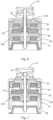
Fig. 1 shows an example of a linear drive for a circuit breaker in open, semi closed, and closed positions; -
Fig. 2 shows an example of a linear drive for a circuit breaker in a closed position; -
Fig. 3 shows an example of the linear drive for a circuit breaker ofFig. 2 in an open position; -
Fig. 4 shows an example of a linear drive for a circuit breaker in a closed position - it is to be noted that a gap is shown aboveplunger 80 but there can be no gap or a very small gap; -
Fig. 5 shows an example of the linear drive for a circuit breaker ofFig. 4 in an open position; -
Fig. 6 shows an example of a linear drive for a circuit breaker in a closed position - the spring 120 s arranged to support the contact force and it is to be noted that a gap is shown aboveplunger 80 but there can be no gap or a very small gap; -
Fig. 7 shows an example of the linear drive for a circuit breaker ofFig. 6 in an open position - thespring 120 is not shown because it has been compressed; -
Fig. 8 shows an example of a linear drive for a circuit breaker in a closed position; -
Fig. 9 shows an example of the linear drive for a circuit breaker ofFig. 8 in an open position - - it is to be noted that a gap is shown aboveplunger 80 but there can be no gap or a very small gap; and -
Figs. 10a -9b show an example of a latching device for a linear drive for a circuit breaker. - The new developments relate to linear drives for circuit breakers, as shown in specific examples of
Figs. 1-9 , and10a-10b . It is to be noted that the following description relates to two-stage drives with two coils and two plungers, but the drive can be a three stage, four stage or N stage drive, with three coils and three plungers, four coils and four plungers, or N coils and N plungers. The movement of the travel can be adjusted by energizing the coils or generating eddy current within a magnetic flux circuit to deaccelerate the drive mechanism. In case the coil(s) will be energized like a Thomson coil the velocity can be even faster. Anyhow the drive will be comparable faster in case all coils are perfectly energized, all gaps to be closed are lower and active like linear motor rail, linear motor device. These drives can even work up to more than 5m/s. - In an example, a linear drive for a circuit breaker comprises:
- a
connection rod 20; - a
first coil 30; - a
first plunger 40; - a
second coil 100; and - a
second plunger 80. - The connection rod is configured to connect to a movable contact of a circuit breaker. Along an axis of the connection rod, the first coil is adjacent to the first plunger and on an opposite side of the first plunger to the second coil, the first plunger is between the first coil and the second coil, and the second plunger is adjacent to the second coil and on an opposite side of the second coil to the first plunger.
- In a first mode of operation:
- activation of the first coil is configured to move the first plunger away from the first coil along the axis of the connection rod in a first direction by a first distance;
- movement of the first plunger along the axis of the connection rod in the first direction is configured to move the second plunger along the axis of the connection rod in the first direction by the first distance;
- activation of the second coil is configured to move the second plunger away from the second coil along the axis of the connection rod in the first direction by a second distance; and
- movement of the second plunger along the axis of the connection rod in the first direction is configured to move the connection rod along the axis of the connection rod in the first direction by a distance equal to the first distance added to the second distance.
- Thus, the coils are pushing the plungers away from them.
- Thus, the connection rod has been moved by a distance equal to the first distance, provided by a first stage of the drive, plus the second distance, provided by a second stage of the drive, but the first stage has only required to move components by the first distance and the second stage only required to move components by the second distance.
- In effect the
first coil 30 and thefirst plunger 40 are part of a first stage and thesecond coil 100 and the second plunger are part of a second stage, and the coil of the first stage activates to move the first plunger that moves the connection rod and the second plunger axially and the coil of the second stage activates to move the second plunger that continues to move the connection rod axially. The overall movement of the connection rod is then provided by a movement from the second stage added to a movement of the first stage. - Thus, rather than a circuit breaker drive in effect closing one large gap, several gaps are closed cumulatively to provide for a larger gap closure.
- In this way, all the gaps can be closed simultaneously through simultaneous activation of the different coils, and a time for an overall closing movement can be reduced and will be more precise at start to close, will close / open with reduced delay from timing.
- However, the coils can operate consecutively, or in an overlapped manner, and the temporal profile of the movement of the movable contact (the travel curve) can be controlled as required.
- Energy consumption is reduced, because in effect all the "gaps" that need to be closed are smaller than one big gap.
- However, in addition very large spacing for contacts of a circuit breaker can be accommodated, where the linear drive can be used to make linear movements of the connection rod of up to 60mm and more. This can be achieved through example by having more stages than the two described above, where there can be a whole series of coils and plungers operating in relay, closing multiple gaps cumulatively to provide a very large overall gap movement.
- According to an example, the second plunger is fixedly connected to the connection rod.
- According to an example, the connection rod comprises a
flange 90. The flange is fixedly connected to the connection rod or the flange is a part of the rod. When the first plunger moves away from the first coil along the axis of the connection rod in the first direction the first plunger is configured to engage with the flange to move the connection rod in the first direction in the first direction by the first distance. - According to an example, the first coil is at a fixed location within the drive.
- According to an example, the second coil is at a fixed location within the drive.
- According to an example, the drive is configured to activate the first coil and the second coil simultaneously.
- According to an example, the drive is configured to activate the first coil and then activate the second coil.
- According to an example, the drive is configured to activate the second coil after activation of the first coil has moved the first plunger away from the first coil along the axis of the connection rod in the first direction by the first distance.
- According to an example, the drive is configured to activate the second coil and then activate the first coil.
- According to an example, the drive is configured to activate the first coil after activation of the second coil has moved the second plunger away from the second coil along the axis of the connection rod in the first direction by the second distance.
- According to an example, the drive comprises a
spring 10. In a second mode of operation the spring is configured to move the connection rod along the axis of the connection rod in a second direction opposite to the first direction by a distance equal to the first distance added to the second distance. - Thus, the coils act in a first mode to push the plungers away from them, and in a second mode the spring can bring the drive back to a start position.
- In other words, the
coils plungers spring 10 supports the open operation. - In an example, a linear drive for a circuit breaker comprises:
- a
connection rod 20; - a
first coil 30; - a
first plunger 40; - a
second coil 100; and - a
second plunger 80. - The connection rod is configured to connect to a movable contact of a circuit breaker. Along an axis of the connection rod, the first coil is adjacent to the first plunger and on an opposite side of the first plunger to the second coil, the first plunger is between the first coil and the second coil, and the second plunger is adjacent to the second coil and on an opposite side of the second coil to the first plunger.
- In a first mode of operation:
- activation of the first coil is configured to move the first plunger toward the first coil along the axis of the connection rod in a first direction by a first distance;
- movement of the first plunger along the axis of the connection rod in the first direction is configured to move the second plunger along the axis of the connection rod in the first direction by the first distance;
- activation of the second coil is configured to move the second plunger toward the second coil along the axis of the connection rod in the first direction by a second distance; and
- movement of the second plunger along the axis of the connection rod in the first direction is configured to move the connection rod along the axis of the connection rod in the first direction by a distance equal to the first distance added to the second distance.
- Thus, the connection rod has been moved by a distance equal to the first distance, provided by a first stage of the drive, plus the second distance, provided by a second stage of the drive, but the first stage has only required to move components by the first distance and the second stage only required to move components by the second distance.
- In effect the
first coil 30 and thefirst plunger 40 are part of a first stage and thesecond coil 100 and the second plunger are part of a second stage, and the coil of the first stage activates to move the first plunger that moves the connection rod and the second plunger axially and the coil of the second stage activates to move the second plunger that continues to move the connection rod axially. The overall movement of the connection rod is then provided by a movement from the second stage added to a movement of the first stage. - Thus, in this example the drive is working in an opposite sense to the previously described drive, where rather than pushing plungers by coils, the coils are pulling plungers towards them.
- According to an example, the second plunger is fixedly connected to the connection rod.
- According to an example, the connection rod comprises a
flange 110. The flange is fixedly connected to the connection rod or the flange is a part of the connection rod. When the first plunger moves toward the first coil along the axis of the connection rod in the first direction the first plunger is configured to engage with the flange to move the connection rod in the first direction in the first direction by the first distance. - In an example, the first coil is at a fixed location within the drive.
- In an example, the second coil is at a fixed location within the drive.
- In an example, the drive is configured to activate the first coil and the second coil simultaneously.
- In an example, the drive is configured to activate the first coil and then activate the second coil.
- In an example, the drive is configured to activate the second coil after activation of the first coil has moved the first plunger toward the first coil along the axis of the connection rod in the first direction by the first distance.
- In an example, the drive is configured to activate the second coil and then activate the first coil.
- In an example, the drive is configured to activate the first coil after activation of the second coil has moved the second plunger toward the second coil along the axis of the connection rod in the first direction by the second distance.
- In an example, the drive comprises a
spring 10. In a second mode of operation the spring is configured to move the connection rod along the axis of the connection rod in a second direction opposite to the first direction by a distance equal to the first distance added to the second distance. - In an example, a linear drive for a circuit breaker comprises:
- a
connection rod 20; - a
first coil 30; - a
first plunger 40; - a
second coil 100; and - a
second plunger 80. - The connection rod is configured to connect to a movable contact of a circuit breaker. Along an axis of the connection rod, the first coil is adjacent to the first plunger and on an opposite side of the first plunger to the second coil, the first plunger is between the first coil and the second coil, and the second plunger is adjacent to the second coil and on an opposite side of the second coil to the first plunger;
- In a first mode of operation:
- activation of the first coil is configured to move the first plunger away from the first coil along the axis of the connection rod in a first direction by a first distance;
- movement of the first plunger along the axis of the connection rod in the first direction is configured to move the second plunger along the axis of the connection rod in the first direction by the first distance;
- activation of the second coil is configured to move the second plunger away from the second coil along the axis of the connection rod in the first direction by a second distance; and
- movement of the second plunger along the axis of the connection rod in the first direction is configured to move the connection rod along the axis of the connection rod in the first direction by a distance equal to the first distance added to the second distance.
- In a second mode of operation:
- activation of the first coil is configured to move the first plunger toward the first coil along the axis of the connection rod in a second direction by the first distance, and wherein the second direction is opposite to the first direction;
- movement of the first plunger along the axis of the connection rod in the second direction is configured to move the second plunger along the axis of the connection rod in the second direction by the first distance;
- activation of the second coil is configured to move the second plunger toward the second coil along the axis of the connection rod in the second direction by a second distance; and
- movement of the second plunger along the axis of the connection rod in the first direction is configured to move the connection rod along the axis of the connection rod in the second direction by a distance equal to the first distance added to the second distance.
- Thus, this example of drive can be considered to be a combination of parts of the above two drives combined together. Now, the coils and plungers are used to move the connection rod in both directions.
- In an example, the second plunger is fixedly connected to the connection rod.
- It is to be noted that the description, for ease or explanation, relates to a two-stage drive, with two sets of coils and two plungers. But the drive can be a multi-stage drive, with three or more sets of coils and three or more associated plungers. When there are numerous coils/plunger, then the last plunger is fixedly connected to the connection rod.
- In an example, the connection rod comprises a
first flange 90. The first flange is fixedly connected to the connection rod or the first flange is a part of the connection rod. When the first plunger moves away from the first coil along the axis of the connection rod in the first direction the first plunger is configured to engage with the first flange to move the connection rod in the first direction in the first direction by the first distance. - In an example, the first coil is at a fixed location within the drive.
- In an example, the second coil is at a fixed location within the drive.
- In an example, in the first mode of operation the drive is configured to activate the first coil and the second coil simultaneously.
- In an example, in the first mode of operation the drive is configured to activate the first coil and then activate the second coil.
- In an example, in the first mode of operation the drive is configured to activate the second coil after activation of the first coil has moved the first plunger away from the first coil along the axis of the connection rod in the first direction by the first distance.
- In an example, in the first mode of operation the drive is configured to activate the second coil and then activate the first coil.
- In an example, in the first mode of operation the drive is configured to activate the first coil after activation of the second coil has moved the second plunger away from the second coil along the axis of the connection rod in the first direction by the second distance.
- In an example, the connection rod comprises a
second flange 110. The second flange is fixedly connected to the connection rod or the second flange is a part of the rod. When the first plunger moves toward the first coil along the axis of the connection rod in the second direction the first plunger is configured to engage with the second flange to move the connection rod in the second direction by the first distance. - In an example, in the second mode of operation the drive is configured to activate the first coil and the second coil simultaneously.
- In an example, in the second mode of operation the drive is configured to activate the first coil and then activate the second coil.
- In an example, in the second mode of operation the drive is configured to activate the second coil after activation of the first coil has moved the first plunger toward the first coil along the axis of the connection rod in the first direction by the first distance.
- In an example, in the second mode of operation the drive is configured to activate the second coil and then activate the first coil.
- In an example, in the second mode of operation the drive is configured to activate the first coil after activation of the second coil has moved the second plunger toward the second coil along the axis of the connection rod in the first direction by the second distance.
- The new linear drives will now be described with respect to several specific embodiments, where reference is made to
Figs. 1-9 and10a -9b. - The inventor's started from the existing position, where a circuit breaker needs a one gap to be closed or opened in a single stroke, which has associated limitations.
- The new development for the new linear drives is to provide a drive that has divided the closing of a single big gap in one step into closing a gap into several smaller steps. Having smaller gaps to be closed provides for better magnetic flux through each open "smaller" gap and increases the magnetic force to close the "smaller" gap and hence the overall gap.
- This provides for better steering of electromechanics drive:
- a faster reaction time is provided
- energy consumption is reduced because all gaps to be closed are smaller (transient sequence).
- the travel curve can be influenced and adjusted to the needs of the particular circuit breaker system / interruption device.
- bigger gaps between contacts of a circuit breaker, even up to 60 and + mm, can be closed/opened through the new electromechanical drives.
- in some applications no permanent magnetic material is needed to provide the holding force.
- remanence of the magnetic circuit can already be sufficient to provide the holding force in end positions, or bistable mechanical latching
Fig. 10 a) b) can be utilised. - Faster movement can be achieved like a linear motor - "rail-gun" -.
- Thus, the movable side of the new drive is directly connected to the main (connection) rod to the interruption device - the circuit breaker. The new development is to move the main rod by using some smaller gaps in the multistage electromagnetic device like a linear motor. That means in the new technique, the main connection rod is moved by in effect drive plates (plungers) which are closing in a row and drive the main rod of drive by a gap distance that is a sum of the smaller gap closures. For example, the first gap will be close quite fast and precisely from the timing perspective. The first stage will close and accelerate the mass of the movable parts. The second, or all further steps, can then close after each other and so the drive will close completely and the needed energy for the complete device operation will be reduced. This is possible because two or more gaps are closed, but here each gap to be closed is smaller than a single a "huge" gap that must be overcome in case of existing one step electromechanical drive. It is to be noted, that this description has all stages closing one after the other, but all stages can close simultaneously if required.
- In the new development, rather than closing/opening one single "big" gap to provide for the required movement of the connection rod, two gaps (but there can be more than two if further stages are utilized) are closed/opened. In an example, all stages are used to close all smaller gaps in a row like a linear motor, and the same can be done during opening in the opposite direction, and here the opening can be better than existing spring based opening, because all stages can be used to accelerate the circuit breaker - however a spring can be used for drive in one direction, with coils and plungers of a set of stages used to close gaps in the other direction. In addition, and thanks to all steps the drive can be steered (the coils) by providing current to each coil separately controlled by an electronic device. Current can be fed to all the coils to allow movement at one time to decrease the open/close time, but then control of the travel curve is not as great as when coils are controlled individually, where in effect there is a serial connection of all magnetic circuits to provide closing and opening of drive. As discussed here, the coils and plungers of each stage can be used to close gaps and move a connection rod in one direction and can also open gaps to move the connection rod in the opposite direction. However, the coils and plungers of each stage can be used to close gaps and move the connection rod in one direction and a
spring 10 can be used to move the connection rod in the opposite, or the coils and plungers of each stage can be used to open gaps and move the connection rod in one direction and a spring can be used to move the connection rod in the opposite. - In the figures
-
Fig. 1 shows an embodiment of the new drive. On the left the drive is in the open configuration.Plunger 40 is attracted towards and moves towardscoils 30 and engages with rand board/flange 110 that is fixed toconnection rod 20 that moves the connection rod upwards. Theplunger 80 is also connected to theconnection rod 20 and is also move upwards. This can be seen in the transition from the open configuration to the semi closed configuration. Then a second stage of closing is made, whereplunger 80 is attracted towards and moves towardscoils 100. This continues to move the connection rod upwards until an overall closure movement has been made that is greater than the individual closing movements. -
Figs. 2 and 3 show an embodiment of the new drive, withFig. 2 showing the drive in a closed configuration for a circuit breaker when closed, where both plungers are in the closed position adjacent to the associated coils, withFig, 3 showing the drive in an open configuration for the circuit breaker when open, where both plungers are in the open position spaced from the associated coils. -
Figs. 4 and 5 show an embodiment of the new drive, withFig. 4 showing the drive in a closed configuration for a circuit breaker when closed. where both plungers are in the closed position adjacent to the associated coils, withFig, 5 showing the drive in an open configuration for the circuit breaker when open, where both plungers are in the open position spaced from the associated coils. -
Figs. 6 and 7 show an embodiment of the new drive, withFig. 6 showing the drive in a closed configuration for a circuit breaker when closed, where both plungers are in the closed position adjacent to the associated coils, withFig, 7 showing the drive in an open configuration for the circuit breaker when open, where both plungers are in the open position spaced from the associated coils. -
Figs. 8 and 9 show an embodiment of the new drive, withFig. 8 showing the drive in a closed configuration for a circuit breaker when closed, where both plungers are in the closed position adjacent to the associated coils, withFig, 9 showing the drive in an open configuration for the circuit breaker when open, where both plungers are in the open position spaced from the associated coils. - In the figures, the
spring 10 is expanded in the open configurations because the connection rod has been driven downwards and the circuit breaker is open, and thespring 10 can then be used to "open" the drive and the circuit breaker. However, thespring 10 is not essential, and thecoils plungers connection rod 20 in both directions. - The following provides an example of required movement of the drives. For example, then can be a contact gap distance of 17mm inside the vacuum interrupter, and the total travel of the linear movement needs to be today 17mm gap plus a 4mm contact spring gap = 21mm to come to a closed position.
- In the new design, to avoid this huge single gap distance to be closed in a drive the new drive uses multi-stages to get the total closing in order that the opening gap is divided into several gaps, which are closed during the operation or opened in the opposite sense. All placed coils can be energized at the same time, and the mechanism starts to close at first with the smallest gap and at the same time the main rod moves in a linear way to close the electromagnetic- mechanical mechanism. The further gap of the plunger at the main rod is moving at the same time to a more closed gap distance and the magnetic force will become higher to move the main rod into the closed position. The way to close is done by the activation of some stages in order to have at any time smaller gaps during the total closing operation, which reduces the needed energy consumption of the full arrangement. It is also possible to energize the coils separately from each other, through an electronic device, to optimize the travel curve of the breaker mechanism and to save energy during the operation as well.
- The stages, which are movable on the main connection rod, can be used to support the holding force at closed (which can be provided by a spring 120) and takes a part of the force which is needed to lower the contact resistance at closed contact position of vacuum interrupter. In the other direction the stages can be used to make a "free wheel" movement at opening and on an arranged board at the rod the free disc/part will be stopped to provide a so called "hammer - effect" to break the unavoidable micro-welding at the point of contact separation inside the interruption / e.g. vacuum interrupter device.
- In case there are two "multi-stage" drives installed in the opposite direction to each other a pulling and a pushing force can be provided like a bi-stable magnetic mechanism by using permanent magnet flux or by a knee construction shown in
Fig.10a /b. The knee mechanism can be made/done inside the main mechanical chain / loop. - Referring to
Fig, 1 ,Figs. 2-3 , andFigs. 4-5 , andFigs. 6-7 . - In the new design of linear drive, or multistage actuator, the full gap distance between
plunger 80 and closed position is provided by two stages at least. The gap between thefirst plunger 40 will be closed in the first step while energizing thecoil 30 to reduce the gap distance by the touch of rand board/flange 90 for the following stage with energizing thecoil 100 withplunger 80. In an example, onepermanent magnet 60 can be used to keep the drive finally in a closed position, as shown inFigs. 2 ,4 , and6 - however the drive can be kept in this position by the coils themselves and/or with a mechanical latch system as shown in figs. 9a-9b. By energizingcoils plunger part 80. The magnetic flux through the ferromagnetic part will weaken the holding force atplunger 80 that based on theopening spring 10 and the electromagnetic- mechanical breaker will operate to the open position shown inFigs. 3 ,5 , and7 - but as discussedspring 10 is not essential. Not shown is the possible placement of the permanent magnet onplunger part 80, that's an alternative to the positioning between thesupport part 50 for the second stage and theferromagnetic parts 70 for the second stage. - In the new design of linear drive, or multistage actuator, the full gap distance between
plunger 80 and closed position is provided by two stages at least. The gap between thefirst plunger 40 will be closed in the first step while energizing thecoil 30 to reduce the gap distance by the touch of rand board/flange 90 for the following stage with energizing thecoil 100 withplunger 80. In an example, only need of onepermanent magnet 60 can be used to keep the drive finally in a closed position as shown inFig. 8 - However the drive can be kept in this position by the coils themselves and/or with a mechanical latch system as shown inFigs. 10a -9b. Here asecond magnet 130 can be located to latch theplunger 40 at the closed position.Plunger 40 can also be latched by using the hysteresis of a selected drive material which allows sufficient hysteresis in magnetizing that a certain magnetic flux is given to keep theplunger 40 in closed position and in this situation a contact closing spring can be applied that will support contact force while at the closed position. If all the stages are designed in such a way to use the hysteresis and magnetic flux on all stages that will be sufficient to keep the mechanism in closed position and in this situation, there are some interacting closing springs in series connected the breaker can be kept close without any use of "strong" permanent magnetic parts. - By energizing
coils plunger parts plungers opening spring 10 the electromagnetic- mechanical breaker will operate to the open position shown inFig.9 . The plunger design can be made in a different way from the construction point of view, and there exist the opportunity to have in different stages different sizes of plunger in diameter and the thickness on each stage that can vary to find optimum structures related with respect to inertia to realize robust mechanical operation. - Instead of using the permanent magnet arrangement for latching, there exists the opportunity to latch the stages by a knee-mechanism
Fig.10a -9b bistable device to provide the held openingFig. 10a or closing positionsFig. 10b . To keep the mechanical solution in a way robust enough in the perspective of long mechanical life and the cost for those parts low, a hybrid solution can be chosen by the use of a knee-mechanism and the use of hysteresis magnetic flux inside the plunger and or the use of more cost-effective magnets with reduced magnetic flux compared to NeFeBo magnets. Thus, in some applications permanent magnetic are not needed with respect to maintaining close or open positions, where ferromagnetic material can be used, and the remanence of material can be used to have fixed drive position without or with less back bounce of the device (Hard magnetic material). - Thus, in general to open may both
coils plunger 40 andplunger 80 downward - as seen inFigs. 1-9 .Plunger 40 engages with aflange 90 of theconnection rod 20 to move the rod downwards by a first distance (a first gap). Here plungers 40 and 80 are acting to open the drive (using the flange 90), and bothcoils connection rod 20 continues with the second stage until the drive is fully open. The coil activation can be simultaneous or can be one after the other or offset by different amounts to change the travel curve or temporal profile of the connection rod movement. Similarly in the closing operation, the coils can be energized together or separately, and indeed a spring can be used to provide the energy to drive in one direction if required. - The discussion above relating to
Figs. 1-9 has related to in effect a two stage system withcoil 30 andplunger 40 forming a first stage andcoil 100 andplunger 80 forming a second stage, but there can be further stages stacked together using the described new development, where the connection rod can be moved by an overall distance (large gap) provided by a summation of individual distances (small gaps) and in this way movements of 60mm, 80mm or even more can be achieved. - The new drive provides the following:
- Using multistage electromagnetic- mechanic drive, each single gap will be smaller to overcome the full and needed complete gap distance, the inertia of the main and final closing part can be lower.
- The total amount of energy consumption can be selected lower because each single gap is smaller to be actuated/moved.
- When closing/opening the drive, the mechanism will react/work more precisely from the timing perspective due to the multistage application and the tolerance of each step/stage inside the drive plays a subordinate role.
- The temperature dependency (in application) has a lower influence on the travel characteristic of the drive.
- Because there is less electric-mechanic energy inside the loop, the impulse at closing can be reduced.
- The final closing/opening force can be supported by the mechanism stages, arranged springs in addition at each stage are supporting the closing and contact force in close position.
- One or more stages can be used to break micro welding between VI contacts at opening.
- Even within the multistage design it will be sufficient to have only one or no permanent magnet in the drive. The magnetic holding effect can be taken from magnetic hysteresis to interacting parts, and/or the permanent magnet, and/or by a knee mechanism integrated in the drive to get a be-stable position. Thus, a hybrid can be arranged at least in one stage.
- In case there are two "multi-stage" drives installed in the opposite direction to each other a pulling and a pushing force can be provided like a bi-stable magnetic mechanism by using permanent magnet flux or by a knee construction shown in
Fig.10a /b. -
- 10 Opening spring
- 20 Connection rod
- 30 Closing/opening coil for
plunger 40 - 40 Plunger to close first stage
- 50 Support part for second stage
- 60 Permanent magnets to keep drive in closed position
- 70 Ferromagnetic parts for second stage
- 80 Plunger in second stage for final operation
- 90 Rand board/flange to allow force from first stage for opening
- 100 Closing/opening coil for
plunger 80 - 110 Rand board/flange to allow closing from first stage to reduce gap in second stage
- 120 Contact opening spring or in the opposite direction on the
flange 90 but not shown here contact force support spring - 130 Permanent magnets to keep drive in closed position, here for the first stage with
plunger 40
Claims (15)
- A linear drive for a circuit breaker, comprising:- a connection rod (20);- a first coil (30);- a first plunger (40);- a second coil (100); and- a second plunger (80);wherein the connection rod is configured to connect to a movable contact of a circuit breaker;wherein along an axis of the connection rod, the first coil is adjacent to the first plunger and on an opposite side of the first plunger to the second coil, the first plunger is between the first coil and the second coil, and the second plunger is adjacent to the second coil and on an opposite side of the second coil to the first plunger;wherein in a first mode of operation:activation of the first coil is configured to move the first plunger away from the first coil along the axis of the connection rod in a first direction by a first distance;movement of the first plunger along the axis of the connection rod in the first direction is configured to move the second plunger along the axis of the connection rod in the first direction by the first distance;activation of the second coil is configured to move the second plunger away from the second coil along the axis of the connection rod in the first direction by a second distance; andmovement of the second plunger along the axis of the connection rod in the first direction is configured to move the connection rod along the axis of the connection rod in the first direction by a distance equal to the first distance added to the second distance.
- Drive according to claim 1, wherein the second plunger is fixedly connected to the connection rod.
- Drive according to any of claims 1-2, wherein the connection rod comprises a flange (90), wherein the flange is fixedly connected to the connection rod or the flange is a part of the rod, and wherein when the first plunger moves away from the first coil along the axis of the connection rod in the first direction the first plunger is configured to engage with the flange to move the connection rod in the first direction in the first direction by the first distance.
- Drive according to any of claims 1-3, wherein the first coil is at a fixed location within the drive.
- Drive according to any of claims 1-4, wherein the second coil is at a fixed location within the drive.
- Drive according to any of claims 1-5, wherein the drive is configured to activate the first coil and the second coil simultaneously.
- Drive according to any of claims 1-5, wherein the drive is configured to activate the first coil and then activate the second coil.
- Drive according to claim 7, wherein the drive is configured to activate the second coil after activation of the first coil has moved the first plunger away from the first coil along the axis of the connection rod in the first direction by the first distance.
- Drive according to any of claims 1-5, wherein the drive is configured to activate the second coil and then activate the first coil.
- Drive according to claim 9, wherein the drive is configured to activate the first coil after activation of the second coil has moved the second plunger away from the second coil along the axis of the connection rod in the first direction by the second distance.
- Drive according to any of claims 1-10, wherein the drive comprises a spring (10), and wherein in a second mode of operation the spring is configured to move the connection rod along the axis of the connection rod in a second direction opposite to the first direction by a distance equal to the first distance added to the second distance.
- A linear drive for a circuit breaker, comprising:- a connection rod (20);- a first coil (30);- a first plunger (40);- a second coil (100); and- a second plunger (80);wherein the connection rod is configured to connect to a movable contact of a circuit breaker;wherein along an axis of the connection rod, the first coil is adjacent to the first plunger and on an opposite side of the first plunger to the second coil, the first plunger is between the first coil and the second coil, and the second plunger is adjacent to the second coil and on an opposite side of the second coil to the first plunger;wherein in a first mode of operation:activation of the first coil is configured to move the first plunger toward the first coil along the axis of the connection rod in a first direction by a first distance;movement of the first plunger along the axis of the connection rod in the first direction is configured to move the second plunger along the axis of the connection rod in the first direction by the first distance;activation of the second coil is configured to move the second plunger toward the second coil along the axis of the connection rod in the first direction by a second distance; andmovement of the second plunger along the axis of the connection rod in the first direction is configured to move the connection rod along the axis of the connection rod in the first direction by a distance equal to the first distance added to the second distance.
- Drive according to claim 12, wherein the second plunger is fixedly connected to the connection rod.
- Drive according to any of claims 12-13, wherein the connection rod comprises a flange (110), wherein the flange is fixedly connected to the connection rod or the flange is a part of the rod, and wherein when the first plunger moves toward the first coil along the axis of the connection rod in the first direction the first plunger is configured to engage with the flange to move the connection rod in the first direction in the first direction by the first distance.
- A linear drive for a circuit breaker, comprising:- a connection rod (20);- a first coil (30);- a first plunger (40);- a second coil (100); and- a second plunger (80);wherein the connection rod is configured to connect to a movable contact of a circuit breaker;wherein along an axis of the connection rod, the first coil is adjacent to the first plunger and on an opposite side of the first plunger to the second coil, the first plunger is between the first coil and the second coil, and the second plunger is adjacent to the second coil and on an opposite side of the second coil to the first plunger;wherein in a first mode of operation:activation of the first coil is configured to move the first plunger away from the first coil along the axis of the connection rod in a first direction by a first distance;movement of the first plunger along the axis of the connection rod in the first direction is configured to move the second plunger along the axis of the connection rod in the first direction by the first distance;activation of the second coil is configured to move the second plunger away from the second coil along the axis of the connection rod in the first direction by a second distance; andmovement of the second plunger along the axis of the connection rod in the first direction is configured to move the connection rod along the axis of the connection rod in the first direction by a distance equal to the first distance added to the second distance;wherein in a second mode of operation:activation of the first coil is configured to move the first plunger toward the first coil along the axis of the connection rod in a second direction by the first distance, and wherein the second direction is opposite to the first direction;movement of the first plunger along the axis of the connection rod in the second direction is configured to move the second plunger along the axis of the connection rod in the second direction by the first distance;activation of the second coil is configured to move the second plunger toward the second coil along the axis of the connection rod in the second direction by a second distance; andmovement of the second plunger along the axis of the connection rod in the first direction is configured to move the connection rod along the axis of the connection rod in the second direction by a distance equal to the first distance added to the second distance.
Priority Applications (1)
| Application Number | Priority Date | Filing Date | Title |
|---|---|---|---|
| EP23189678.8A EP4503076A1 (en) | 2023-08-04 | 2023-08-04 | Linear drive for a circuit breaker |
Applications Claiming Priority (1)
| Application Number | Priority Date | Filing Date | Title |
|---|---|---|---|
| EP23189678.8A EP4503076A1 (en) | 2023-08-04 | 2023-08-04 | Linear drive for a circuit breaker |
Publications (1)
| Publication Number | Publication Date |
|---|---|
| EP4503076A1 true EP4503076A1 (en) | 2025-02-05 |
Family
ID=87557679
Family Applications (1)
| Application Number | Title | Priority Date | Filing Date |
|---|---|---|---|
| EP23189678.8A Pending EP4503076A1 (en) | 2023-08-04 | 2023-08-04 | Linear drive for a circuit breaker |
Country Status (1)
| Country | Link |
|---|---|
| EP (1) | EP4503076A1 (en) |
Citations (3)
| Publication number | Priority date | Publication date | Assignee | Title |
|---|---|---|---|---|
| US6791442B1 (en) * | 2003-11-21 | 2004-09-14 | Trombetta, Llc | Magnetic latching solenoid |
| WO2008023365A1 (en) * | 2006-08-21 | 2008-02-28 | Arcoline Ltd. | Medium-voltage circuit-breaker |
| FR3111007A1 (en) * | 2020-05-26 | 2021-12-03 | Supergrid Institute | Induction controlled vacuum interrupter switch minimizes vibration |
-
2023
- 2023-08-04 EP EP23189678.8A patent/EP4503076A1/en active Pending
Patent Citations (3)
| Publication number | Priority date | Publication date | Assignee | Title |
|---|---|---|---|---|
| US6791442B1 (en) * | 2003-11-21 | 2004-09-14 | Trombetta, Llc | Magnetic latching solenoid |
| WO2008023365A1 (en) * | 2006-08-21 | 2008-02-28 | Arcoline Ltd. | Medium-voltage circuit-breaker |
| FR3111007A1 (en) * | 2020-05-26 | 2021-12-03 | Supergrid Institute | Induction controlled vacuum interrupter switch minimizes vibration |
Similar Documents
| Publication | Publication Date | Title |
|---|---|---|
| EP3900000B1 (en) | Electrical switching apparatus, and thomson coil actuator and disc member therefor | |
| AU2010332675B2 (en) | Electromagnetic actuator having magnetic coupling, and cutoff device comprising such actuator | |
| US10361050B2 (en) | Accelerated motion relay | |
| EP2312605B1 (en) | Bistable magnetic actuator for a medium voltage circuit breaker | |
| EP0587611B1 (en) | Dc relay device | |
| US7843293B1 (en) | Bistable magnetic drive for a switch | |
| US20200066468A1 (en) | Vacuum Circuit Interrupter with Actuation Having Active Damping | |
| US12567548B2 (en) | Accelerated motion relay | |
| EP3761337B1 (en) | Electromagnetic actuator, switch, and switch gear | |
| US20070273461A1 (en) | Electro-Magnetic Force Driving Actuator and Circuit Breaker Using the Same | |
| EP2551881B1 (en) | Actuator for a circuit breaker | |
| US20160012997A1 (en) | Electric Switch | |
| CN104685599B (en) | Performs device and off device for vacuum switch tube | |
| EP4503076A1 (en) | Linear drive for a circuit breaker | |
| Lammers et al. | MV vacuum switchgear based on magnetic actuators | |
| KR20180120987A (en) | Contact switch | |
| KR101856193B1 (en) | Solenoid apparatus | |
| EP4000084B1 (en) | Circuit breaker | |
| EP4418299A1 (en) | Switch assembly, contactor device and transportation vehicle | |
| EP2862249B1 (en) | Permanent magnet moc latch for the seismic qualification of a withdrawable switchgear | |
| EP2388793A1 (en) | Actuator, tripping device and switch | |
| EP1157399B1 (en) | Power switch |
Legal Events
| Date | Code | Title | Description |
|---|---|---|---|
| PUAI | Public reference made under article 153(3) epc to a published international application that has entered the european phase |
Free format text: ORIGINAL CODE: 0009012 |
|
| STAA | Information on the status of an ep patent application or granted ep patent |
Free format text: STATUS: THE APPLICATION HAS BEEN PUBLISHED |
|
| AK | Designated contracting states |
Kind code of ref document: A1 Designated state(s): AL AT BE BG CH CY CZ DE DK EE ES FI FR GB GR HR HU IE IS IT LI LT LU LV MC ME MK MT NL NO PL PT RO RS SE SI SK SM TR |
|
| STAA | Information on the status of an ep patent application or granted ep patent |
Free format text: STATUS: REQUEST FOR EXAMINATION WAS MADE |
|
| 17P | Request for examination filed |
Effective date: 20250731 |
|
| GRAP | Despatch of communication of intention to grant a patent |
Free format text: ORIGINAL CODE: EPIDOSNIGR1 |
|
| STAA | Information on the status of an ep patent application or granted ep patent |
Free format text: STATUS: GRANT OF PATENT IS INTENDED |
|
| INTG | Intention to grant announced |
Effective date: 20260325 |