EP4502978A1 - Device for controlling mobile body, method for controlling mobile body, and storage medium - Google Patents
Device for controlling mobile body, method for controlling mobile body, and storage medium Download PDFInfo
- Publication number
- EP4502978A1 EP4502978A1 EP22935034.3A EP22935034A EP4502978A1 EP 4502978 A1 EP4502978 A1 EP 4502978A1 EP 22935034 A EP22935034 A EP 22935034A EP 4502978 A1 EP4502978 A1 EP 4502978A1
- Authority
- EP
- European Patent Office
- Prior art keywords
- mobile object
- roadway
- moving
- speed
- score
- Prior art date
- Legal status (The legal status is an assumption and is not a legal conclusion. Google has not performed a legal analysis and makes no representation as to the accuracy of the status listed.)
- Granted
Links
Images




Classifications
-
- B—PERFORMING OPERATIONS; TRANSPORTING
- B60—VEHICLES IN GENERAL
- B60W—CONJOINT CONTROL OF VEHICLE SUB-UNITS OF DIFFERENT TYPE OR DIFFERENT FUNCTION; CONTROL SYSTEMS SPECIALLY ADAPTED FOR HYBRID VEHICLES; ROAD VEHICLE DRIVE CONTROL SYSTEMS FOR PURPOSES NOT RELATED TO THE CONTROL OF A PARTICULAR SUB-UNIT
- B60W30/00—Purposes of road vehicle drive control systems not related to the control of a particular sub-unit, e.g. of systems using conjoint control of vehicle sub-units
- B60W30/14—Adaptive cruise control
- B60W30/143—Speed control
- B60W30/146—Speed limiting
-
- B—PERFORMING OPERATIONS; TRANSPORTING
- B60—VEHICLES IN GENERAL
- B60W—CONJOINT CONTROL OF VEHICLE SUB-UNITS OF DIFFERENT TYPE OR DIFFERENT FUNCTION; CONTROL SYSTEMS SPECIALLY ADAPTED FOR HYBRID VEHICLES; ROAD VEHICLE DRIVE CONTROL SYSTEMS FOR PURPOSES NOT RELATED TO THE CONTROL OF A PARTICULAR SUB-UNIT
- B60W30/00—Purposes of road vehicle drive control systems not related to the control of a particular sub-unit, e.g. of systems using conjoint control of vehicle sub-units
- B60W30/14—Adaptive cruise control
- B60W30/16—Control of distance between vehicles, e.g. keeping a distance to preceding vehicle
- B60W30/162—Speed limiting therefor
-
- B—PERFORMING OPERATIONS; TRANSPORTING
- B60—VEHICLES IN GENERAL
- B60W—CONJOINT CONTROL OF VEHICLE SUB-UNITS OF DIFFERENT TYPE OR DIFFERENT FUNCTION; CONTROL SYSTEMS SPECIALLY ADAPTED FOR HYBRID VEHICLES; ROAD VEHICLE DRIVE CONTROL SYSTEMS FOR PURPOSES NOT RELATED TO THE CONTROL OF A PARTICULAR SUB-UNIT
- B60W30/00—Purposes of road vehicle drive control systems not related to the control of a particular sub-unit, e.g. of systems using conjoint control of vehicle sub-units
- B60W30/18—Propelling the vehicle
-
- G—PHYSICS
- G05—CONTROLLING; REGULATING
- G05D—SYSTEMS FOR CONTROLLING OR REGULATING NON-ELECTRIC VARIABLES
- G05D1/00—Control of position, course, altitude or attitude of land, water, air or space vehicles, e.g. using automatic pilots
- G05D1/60—Intended control result
- G05D1/65—Following a desired speed profile
-
- B—PERFORMING OPERATIONS; TRANSPORTING
- B60—VEHICLES IN GENERAL
- B60W—CONJOINT CONTROL OF VEHICLE SUB-UNITS OF DIFFERENT TYPE OR DIFFERENT FUNCTION; CONTROL SYSTEMS SPECIALLY ADAPTED FOR HYBRID VEHICLES; ROAD VEHICLE DRIVE CONTROL SYSTEMS FOR PURPOSES NOT RELATED TO THE CONTROL OF A PARTICULAR SUB-UNIT
- B60W2300/00—Indexing codes relating to the type of vehicle
- B60W2300/34—Compact city vehicles, e.g., microcars or kei cars
-
- B—PERFORMING OPERATIONS; TRANSPORTING
- B60—VEHICLES IN GENERAL
- B60W—CONJOINT CONTROL OF VEHICLE SUB-UNITS OF DIFFERENT TYPE OR DIFFERENT FUNCTION; CONTROL SYSTEMS SPECIALLY ADAPTED FOR HYBRID VEHICLES; ROAD VEHICLE DRIVE CONTROL SYSTEMS FOR PURPOSES NOT RELATED TO THE CONTROL OF A PARTICULAR SUB-UNIT
- B60W2420/00—Indexing codes relating to the type of sensors based on the principle of their operation
- B60W2420/40—Photo, light or radio wave sensitive means, e.g. infrared sensors
- B60W2420/403—Image sensing, e.g. optical camera
-
- B—PERFORMING OPERATIONS; TRANSPORTING
- B60—VEHICLES IN GENERAL
- B60W—CONJOINT CONTROL OF VEHICLE SUB-UNITS OF DIFFERENT TYPE OR DIFFERENT FUNCTION; CONTROL SYSTEMS SPECIALLY ADAPTED FOR HYBRID VEHICLES; ROAD VEHICLE DRIVE CONTROL SYSTEMS FOR PURPOSES NOT RELATED TO THE CONTROL OF A PARTICULAR SUB-UNIT
- B60W2552/00—Input parameters relating to infrastructure
- B60W2552/05—Type of road, e.g. motorways, local streets, paved or unpaved roads
-
- B—PERFORMING OPERATIONS; TRANSPORTING
- B60—VEHICLES IN GENERAL
- B60W—CONJOINT CONTROL OF VEHICLE SUB-UNITS OF DIFFERENT TYPE OR DIFFERENT FUNCTION; CONTROL SYSTEMS SPECIALLY ADAPTED FOR HYBRID VEHICLES; ROAD VEHICLE DRIVE CONTROL SYSTEMS FOR PURPOSES NOT RELATED TO THE CONTROL OF A PARTICULAR SUB-UNIT
- B60W2552/00—Input parameters relating to infrastructure
- B60W2552/50—Barriers
-
- B—PERFORMING OPERATIONS; TRANSPORTING
- B60—VEHICLES IN GENERAL
- B60W—CONJOINT CONTROL OF VEHICLE SUB-UNITS OF DIFFERENT TYPE OR DIFFERENT FUNCTION; CONTROL SYSTEMS SPECIALLY ADAPTED FOR HYBRID VEHICLES; ROAD VEHICLE DRIVE CONTROL SYSTEMS FOR PURPOSES NOT RELATED TO THE CONTROL OF A PARTICULAR SUB-UNIT
- B60W2552/00—Input parameters relating to infrastructure
- B60W2552/53—Road markings, e.g. lane marker or crosswalk
-
- B—PERFORMING OPERATIONS; TRANSPORTING
- B60—VEHICLES IN GENERAL
- B60W—CONJOINT CONTROL OF VEHICLE SUB-UNITS OF DIFFERENT TYPE OR DIFFERENT FUNCTION; CONTROL SYSTEMS SPECIALLY ADAPTED FOR HYBRID VEHICLES; ROAD VEHICLE DRIVE CONTROL SYSTEMS FOR PURPOSES NOT RELATED TO THE CONTROL OF A PARTICULAR SUB-UNIT
- B60W2554/00—Input parameters relating to objects
- B60W2554/20—Static objects
-
- B—PERFORMING OPERATIONS; TRANSPORTING
- B60—VEHICLES IN GENERAL
- B60W—CONJOINT CONTROL OF VEHICLE SUB-UNITS OF DIFFERENT TYPE OR DIFFERENT FUNCTION; CONTROL SYSTEMS SPECIALLY ADAPTED FOR HYBRID VEHICLES; ROAD VEHICLE DRIVE CONTROL SYSTEMS FOR PURPOSES NOT RELATED TO THE CONTROL OF A PARTICULAR SUB-UNIT
- B60W2554/00—Input parameters relating to objects
- B60W2554/40—Dynamic objects, e.g. animals, windblown objects
- B60W2554/404—Characteristics
- B60W2554/4041—Position
-
- B—PERFORMING OPERATIONS; TRANSPORTING
- B60—VEHICLES IN GENERAL
- B60W—CONJOINT CONTROL OF VEHICLE SUB-UNITS OF DIFFERENT TYPE OR DIFFERENT FUNCTION; CONTROL SYSTEMS SPECIALLY ADAPTED FOR HYBRID VEHICLES; ROAD VEHICLE DRIVE CONTROL SYSTEMS FOR PURPOSES NOT RELATED TO THE CONTROL OF A PARTICULAR SUB-UNIT
- B60W2556/00—Input parameters relating to data
- B60W2556/40—High definition maps
-
- B—PERFORMING OPERATIONS; TRANSPORTING
- B60—VEHICLES IN GENERAL
- B60W—CONJOINT CONTROL OF VEHICLE SUB-UNITS OF DIFFERENT TYPE OR DIFFERENT FUNCTION; CONTROL SYSTEMS SPECIALLY ADAPTED FOR HYBRID VEHICLES; ROAD VEHICLE DRIVE CONTROL SYSTEMS FOR PURPOSES NOT RELATED TO THE CONTROL OF A PARTICULAR SUB-UNIT
- B60W2720/00—Output or target parameters relating to overall vehicle dynamics
- B60W2720/10—Longitudinal speed
-
- G—PHYSICS
- G05—CONTROLLING; REGULATING
- G05D—SYSTEMS FOR CONTROLLING OR REGULATING NON-ELECTRIC VARIABLES
- G05D2107/00—Specific environments of the controlled vehicles
- G05D2107/10—Outdoor regulated spaces
- G05D2107/13—Spaces reserved for vehicle traffic, e.g. roads, regulated airspace or regulated waters
-
- G—PHYSICS
- G05—CONTROLLING; REGULATING
- G05D—SYSTEMS FOR CONTROLLING OR REGULATING NON-ELECTRIC VARIABLES
- G05D2107/00—Specific environments of the controlled vehicles
- G05D2107/10—Outdoor regulated spaces
- G05D2107/17—Spaces with priority for humans, e.g. populated areas, pedestrian ways, parks or beaches
Definitions
- the present invention relates to a mobile object control device, a mobile object control method, and a storage medium.
- Patent Documents 1 to 4 documents considering a process of recognizing whether a mobile object is moving on a sidewalk or a roadway have been disclosed.
- the present invention has been made in consideration of such circumstances and an objective of the present invention is to provide a mobile object control device, a mobile object control method, and a storage medium for enabling whether a mobile object is moving on a roadway or in a predetermined region different from the roadway to be appropriately recognized.
- a mobile object control device, a mobile object control method, and a storage medium according to the present invention adopt the following configurations.
- a mobile object moves both on a roadway and in a predetermined region different from the roadway.
- the mobile object may be referred to as micromobility.
- An electric kickboard is a type of micromobility.
- the mobile object may be a vehicle that an occupant can board or may be an autonomous mobile object capable of performing unmanned autonomous movement.
- the autonomous mobile object is used, for example, for an application to transport cargo or the like.
- the predetermined region is, for example, a sidewalk.
- the predetermined region may be a part or all of a roadside strip, a bicycle lane, a public open space, or the like or may include all sidewalks, roadside strips, bicycle lanes, public open spaces, and the like.
- the predetermined region is a sidewalk.
- a part described as the "sidewalk” can be read as the "predetermined region” as appropriate.
- FIG. 1 is a diagram showing an example of a configuration of the mobile object 1 and the control device 100 according to the embodiment.
- the mobile object 1 includes, for example, an external environment detection device 10, a mobile object sensor 12, a manipulation element 14, an internal camera 16, a positioning device 18, a mode changeover switch 22, a moving mechanism 30, a drive device 40, an external notification device 50, a storage device 70, and a control device 100. Also, some constituent elements not essential for implementing the functions of the present invention may be omitted.
- the external environment detection device 10 includes various types of devices in which a movement direction of the mobile object 1 is designated as a detection range.
- the external environment detection device 10 includes an external camera, a radar device, a light detection and ranging (LIDAR) sensor, a sensor fusion device, and the like.
- the external environment detection device 10 outputs information indicating a detection result (an image, a position of a physical object, or the like) to the control device 100.
- the mobile object sensor 12 includes, for example, a speed sensor, an acceleration sensor, a yaw rate (angular velocity) sensor, an orientation sensor, a manipulation quantity detection sensor attached to the manipulation element 14, and the like.
- the manipulation element 14 includes, for example, a manipulation element for issuing an acceleration/deceleration instruction (for example, an accelerator pedal or a brake pedal) and a manipulation element for issuing a steering instruction (for example, a steering wheel).
- the mobile object sensor 12 may include an accelerator opening degree sensor, a brake depression amount sensor, a steering torque sensor, and the like.
- the mobile object 1 may include a type of manipulation element other than the above manipulation elements (for example, a non-annular rotation manipulation element, a joystick, a button, or the like) as the manipulation element 14.
- the internal camera 16 images at least a head of the occupant of the mobile object 1 from the front.
- the internal camera 16 is a digital camera that uses an imaging element such as a charge-coupled device (CCD) or a complementary metal oxide semiconductor (CMOS).
- CCD charge-coupled device
- CMOS complementary metal oxide semiconductor
- the internal camera 16 outputs a captured image to the control device 100.
- the positioning device 18 is a device for measuring a position of the mobile object 1.
- the positioning device 18 is, for example, a global navigation satellite system (GNSS) receiver, and identifies the position of the mobile object 1 on the basis of a signal received from a GNSS satellite and outputs the identified position as position information.
- the position information of the mobile object 1 may be estimated from a position of a Wi-Fi base station to which a communication device to be described below is connected.
- the mode changeover switch 22 is a switch to be manipulated by the occupant.
- the mode changeover switch 22 may be a mechanical switch or a graphical user interface (GUI) switch set on the touch panel.
- the mode changeover switch 22 receives a manipulation for switching a driving mode to any one of, for example, mode A that is an assist mode in which one of the steering manipulation and acceleration/deceleration control is performed by the occupant and the other is performed automatically and that may be mode A-1 in which the steering manipulation is performed by the occupant and the acceleration/deceleration control is performed automatically or mode A-2 in which an acceleration/deceleration manipulation is performed by the occupant and the steering control is performed automatically, mode B that is a manual driving mode in which the steering manipulation and the acceleration/deceleration manipulation are performed by the occupant, and mode C that is an automated driving mode in which the steering control and the acceleration/deceleration control are performed automatically.
- mode A is an assist mode in which one of the steering manipulation and acceleration/deceleration control is performed by the
- the moving mechanism 30 is a mechanism for moving the mobile object 1 on the road.
- the moving mechanism 30 is, for example, a wheel group that includes a steered wheel and a driven wheel.
- the moving mechanism 30 may be a leg unit for multi-legged walking.
- the drive device 40 outputs a force to the moving mechanism 30 so that the mobile object 1 can be moved.
- the drive device 40 includes a motor that drives the driven wheel, a battery that stores electric power to be supplied to the motor, a steering device that adjusts the steering angle of the steered wheel, and the like.
- the drive device 40 may include an internal combustion engine, a fuel cell, or the like as a driving force output means or an electric power generation means.
- the drive device 40 may further include a braking device using a friction force or air resistance.
- the external notification device 50 is, for example, a lamp, a display device, a speaker, or the like provided on an outer plate portion of the mobile object 1 and configured to provide a notification of information to the outside of the mobile object 1.
- the external notification device 50 performs different operations in a state in which the mobile object 1 is moving on the sidewalk and a state in which the mobile object 1 is moving on the roadway.
- the external notification device 50 is controlled so that light of the lamp is emitted when the mobile object 1 is moving on the sidewalk and light of the lamp is not emitted when the mobile object 1 is moving on the roadway.
- the color of the light emitted by this lamp is preferably a color specified by law.
- the external notification device 50 may be controlled so that the light of the lamp is emitted in green when the mobile object 1 is moving on the sidewalk and the light of the lamp is emitted in blue when the mobile object 1 is moving on the roadway.
- the external notification device 50 is a display device
- the external notification device 50 displays text or a graphic indicating "moving on the sidewalk" when the mobile object 1 is moving on the sidewalk.
- FIG. 2 is a perspective view of the mobile object 1 viewed from above.
- FW denotes the steered wheel
- RW denotes the driven wheel
- SD denotes the steering device
- MT denotes the motor
- BT denotes the battery.
- the steering device SD, the motor MT, and the battery BT are included in the drive device 40.
- AP denotes the accelerator pedal
- BP denotes the brake pedal
- WH denotes the steering wheel
- SP denotes the speaker
- MC denotes a microphone.
- the mobile object 1 shown in FIG. 2 is a single-seater mobile object and an occupant P is seated in the driver's seat DS and wearing a seat belt SB.
- An arrow D1 indicates a movement direction (a speed vector) of the mobile object 1.
- the external environment detection device 10 is provided near a front end of the mobile object 1
- the internal camera 16 is provided at a position where the head of the occupant P can be imaged from the front of the occupant P
- the mode changeover switch 22 is provided on a boss portion of the steering wheel WH.
- the external notification device 50 serving as a display device is provided near the front end of the mobile object 1.
- the storage device 70 is, for example, a non-transitory storage device such as a hard disk drive (HDD), a flash memory, or a random-access memory (RAM).
- the storage device 70 stores map information 72, a program 74 to be executed by the control device 100, and the like.
- the storage device 70 is shown outside a frame of the control device 100 in FIG. 1 , the storage device 70 may be included in the control device 100.
- the storage device 70 may be provided on a server (not shown).
- the control device 100 includes, for example, a road type recognition unit 120, a physical object recognition unit 130, and a control unit 140.
- These constituent elements are implemented, for example, by a hardware processor such as a central processing unit (CPU) executing a program (software) 74.
- a hardware processor such as a central processing unit (CPU) executing a program (software) 74.
- some or all of these constituent elements may be implemented by hardware (including a circuit unit; circuitry) such as a large-scale integration (LSI) circuit, an application-specific integrated circuit (ASIC), a field-programmable gate array (FPGA), or a graphics processing unit (GPU) or may be implemented by software and hardware in cooperation.
- the program may be pre-stored in the storage device 70 or may be stored in a removable storage medium (a non-transitory storage medium) such as a DVD or a CD-ROM and installed in the storage device 70 when the storage medium is mounted in a drive device.
- the road type recognition unit 120 recognizes whether the mobile object 1 is moving on the roadway or the sidewalk. For example, the road type recognition unit 120 recognizes whether the mobile object 1 is moving on the roadway or the sidewalk by analyzing an image captured by the external camera of the external environment detection device 10. Also, the output of a radar device, a LIDAR sensor, a sensor fusion device, or the like may be used in an auxiliary way.
- the road type recognition unit 120 adds a point value to a roadway score Sr every time each of the plurality of first events indicating that the mobile object 1 is moving on the roadway is recognized in the image captured by the external camera, and recognizes that the mobile object 1 is moving on the roadway when the roadway score Sr is greater than or equal to a first threshold value.
- the road type recognition unit 120 weights a point value in accordance with a degree of confidence when each of the plurality of first events has been recognized and adds the weighted point value to the roadway score Sr.
- Point values corresponding to the first events are denoted by P1 to Pn (n is a natural number and is equal to the number of events assumed as the first event).
- the point values P1 to Pn may be the same value or may be different values according to types of first events. Moreover, it is assumed that the weight corresponding to the degree of confidence of a recognition process is ⁇ 1 to ⁇ n. The degree of confidence of the recognition process is incidentally output in the process of recognizing the first event (including, for example, a discrimination process using a trained model by machine learning).
- the road type recognition unit 120 has recognized any one of a plurality of second events indicating that the mobile object 1 is moving on the sidewalk in the image captured by the external camera, it is recognized that the mobile object 1 is moving on the sidewalk regardless of the roadway score Sr.
- the road type recognition unit 120 classifies and labels pixels within a frame of the image according to semantic segmentation and assumes a plurality of virtual division regions and their boundary lines.
- the road type recognition unit 120 performs at least a process of classifying the region of the image captured by the external camera into a region where the mobile object 1 is located (hereinafter referred to as a host region) and a region where the mobile object 1 is not located adjacent to the region (hereinafter referred to as an adjacent region).
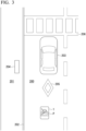
- FIG. 3 is a diagram showing a plurality of first events.
- the first events include, for example, two or more events among event (A) in which there is no static obstacle 204 other than a vehicle 203 in a host region 200 (i.e., inside the outer edge of the region where the mobile object 1 is located), event (B) in which the vehicle 203 is moving in the host region 200, event (C) in which there is a road surface marking 205 on a road surface of the host region 200, event (D) in which there is a crosswalk 206 in the host region 200, and event (E) in which the host region 200 is located on a lower side with respect to a step 202.
- event (A) in which there is no static obstacle 204 other than a vehicle 203 in a host region 200 (i.e., inside the outer edge of the region where the mobile object 1 is located)
- event (B) in which the vehicle 203 is moving in the host region 200 event (C) in which there is a road surface marking 205 on
- Static obstacles are, for example, standing signboards, mailboxes, telephone poles, garbage bins, and the like, which are not classified as mobile objects or traffic participants. Because the static obstacles are rarely placed on the roadway in general, the road type recognition unit 120 increases a value of the roadway score when there is no static obstacle 204 in its host region 200. Moreover, because a region where the vehicle 203 is moving is a roadway with a high probability, the road type recognition unit 120 increases the value of the roadway score when the vehicle 203 is moving in the host region 200. Moreover, because the road surface marking 205 is generally drawn on the roadway, the road type recognition unit 120 increases the value of the roadway score when the road surface marking 205 is located in the host region 200.
- the road type recognition unit 120 increases the value of the roadway score when the crosswalk 206 is located in the host region 200. Moreover, because the sidewalk is generally located on the upper side of the step with respect to the roadway, the road type recognition unit 120 increases the value of the roadway score when the host region 200 is located on the lower side with respect to the step 202.
- FIG. 4 is a diagram showing a plurality of second events.
- the second events include, for example, one or more events among event (a) in which a second surface 207b facing the sidewalk side between two surfaces of a guardrail 207 has been imaged by the external camera, event (b) in which a braille block 208 is located on the road surface of the host region 200, event (c) in which there is a static obstacle 204 other than the vehicle 203 in the host region 200, event (d) in which the host region 200 is located on the upper side with respect to the step 202.
- the guardrail 207 includes a first surface 207a facing the roadway side and a second surface 207b facing the sidewalk side and is installed on the road to match its direction.
- the second surface 207b is imaged by the external camera, it is inferred that the mobile object 1 is moving on the sidewalk with a high probability.
- braille blocks are laid only on sidewalks.
- the static obstacle 204 and the step 202 are as described in the first event.
- FIG. 5 is a diagram showing the second surface 207b facing the sidewalk side of the guardrail 207. As shown in FIG. 5 , it is characterized that the second surface 207b has supports 207c on a front side compared to the first surface and is formed so that it is bent in the order of recess ⁇ projection ⁇ recess in a downward direction from the upper end.
- the second surface 207b can be trained by a trained model and discriminated by image analysis.
- the mobile object 1 is moving on the roadway or in a predetermined region different from the roadway by designating the first event as a factor for increasing the roadway score Sr and recognizing that the mobile object 1 is moving on the roadway when the roadway score Sr is greater than or equal to a first threshold value Th1 and the second event is not recognized.
- the mobile object 1 is permitted to move at a higher speed when the mobile object 1 moves on the roadway than when the mobile object 1 moves on the sidewalk. Therefore, conditions for recognizing that the mobile object 1 is moving on the roadway are preferably set conservatively compared with conditions for recognizing that the mobile object 1 is moving on the sidewalk in consideration of safety aspects.
- the validity of a recognition result can be ensured by designating the first event as a condition for increasing a point value instead of a condition for immediately recognizing the region as a roadway and designating the second event as a condition for immediately recognizing the region as a sidewalk.
- the road type recognition unit 120 may collate position information of the mobile object 1 with the map information 72 and recognize whether the mobile object 1 is moving on the roadway or the sidewalk. In this case, the map information needs to be accurate enough to distinguish the sidewalk and the roadway from position coordinates. Moreover, when the "predetermined region" is not only a sidewalk, the road type recognition unit 120 also performs similar processes for roadside strips, bicycle lanes, public open spaces, and the like.
- FIG. 6 is a flowchart showing an example of a flow of a process executed by the road type recognition unit 120 of the first embodiment.
- the road type recognition unit 120 acquires information for recognition, such as an image of the external camera (step S300).
- the argument k is identification information of the first event.
- the road type recognition unit 120 determines whether or not first event k has been recognized (step S302) and a product of a coefficient ⁇ k and a point value Pk is added to the roadway score Sr when first event k has been recognized (step S304).
- the argument j is identification information of the second event and m is a natural number.
- step S312 When a positive determination result has been obtained even once in the determination processing of step S306 performed up to m times, the road type recognition unit 120 recognizes that the mobile object 1 is moving on the sidewalk (step S312).
- the road type recognition unit 120 determines whether or not the roadway score Sr is greater than or equal to the first threshold value Th1 (step S308). When it is determined that the roadway score Sr is greater than or equal to the first threshold value Th1, the road type recognition unit 120 recognizes that the mobile object 1 is moving on the roadway (step S310). When the roadway score Sr is less than the first threshold value Th1, strictly speaking, it is not recognized with a sufficient degree of confidence whether the mobile object 1 is moving on the roadway or the sidewalk, but the road type recognition unit 120 recognizes that the mobile object 1 is moving on the sidewalk in consideration of safety aspects (step S312).
- the physical object recognition unit 130 recognizes a physical object located near the mobile object 1 on the basis of an output of the external environment detection device 10.
- Physical objects include some or all of mobile objects such as a vehicle, a bicycle, and a pedestrian, course boundaries such as a road marking, a step, a guardrail, a road shoulder, a median strip, structures installed on the road such as a road sign and a signboard, and an obstacle such as a falling object located (having fallen) on the course.
- the physical object recognition unit 130 acquires information such as the presence, position, and type of another mobile object when an image captured by the external camera of the external environment detection device 10 is input to a trained model that has been trained to output information such as the presence, position, and type of a physical object if the image captured by the external camera is input.
- a type of the other mobile object can also be estimated on the basis of a size in the image and/or the intensity of reflected waves received by the radar device of the external environment detection device 10.
- the physical object recognition unit 130 acquires, for example, the speed of another mobile object detected by the radar device using a Doppler shift or the like.
- the control unit 140 controls, for example, the drive device 40 in accordance with a set driving mode. Also, the mobile object 1 may execute only some of the following driving modes, but the control unit 140 sets different speed limit values when the mobile object 1 moves on the roadway and when the mobile object 1 moves on the sidewalk in any case. In this case, the mode changeover switch 22 may be omitted.
- the control unit 140 controls the motor MT of the drive device 40 so that a distance from a physical object located in front of the mobile object 1 is maintained at a certain distance or more when the mobile object 1 moves on the roadway and the mobile object 1 moves at a first speed V1 (e.g., a speed of 10 [km/h] or more and less than several tens of kilometers per hour [km/h]) when a distance from a physical object located in front of the mobile object 1 is sufficiently long with reference to information about a course and a physical object based on the output of the physical object recognition unit 130.
- V1 e.g., a speed of 10 [km/h] or more and less than several tens of kilometers per hour [km/h]
- the control unit 140 controls the motor MT of the drive device 40 so that a distance from a physical object located in front of the mobile object 1 is maintained at a certain distance or more when the mobile object 1 moves on the sidewalk and the mobile object 1 moves at the second speed V2 (for example, a speed of less than 10 [km/h]) when a distance from a physical object located in front of the mobile object 1 is sufficiently long.
- This function is similar to an adaptive cruise control (ACC) function of a vehicle in which the first speed V1 or the second speed V2 is designated as the set speed and the technology used in ACC can be used.
- ACC adaptive cruise control
- control unit 140 controls the steering device SD so that a steering angle of the steered wheel is changed on the basis of a manipulation quantity of the manipulation element 14 such as the steering wheel.
- This function is similar to that of a power steering device and the technology used in the power steering device can be used.
- electronic control is not performed in relation to steering and the mobile object 1 may include a steering device in which the manipulation element 14 and the steering mechanism are mechanically connected.
- the control unit 140 controls the steering device SD of the drive device 40 so that a target trajectory along which the mobile object 1 can move while avoiding a physical object within the course is generated with reference to information about the course and the physical object based on the output of the physical object recognition unit 130 and the mobile object 1 moves along the target trajectory.
- the control unit 140 controls the motor MT of the drive device 40 on the basis of the speed of the mobile object 1 and the manipulation quantity of the accelerator pedal or the brake pedal.
- the control unit 140 controls the motor MT of the drive device 40 in a state in which the first speed V1 is designated as the upper limit speed (wherein this control indicates that the mobile object 1 is not accelerated even if there is a further acceleration instruction when the mobile object 1 reaches the upper limit speed in the case of mode A-2) when the mobile object 1 is moving on the roadway and controls the drive device 40 in a state in which the second speed V2 is designated as the upper limit speed when the mobile object 1 is moving on the sidewalk.
- the second event is recognized and the roadway score Sr is greater than or equal to the second threshold value Th2
- the second event is likely to have been recognized due to the fact that the recognition of the second event has been misrecognition, a static obstacle has been accidentally placed on the roadway, or the roadway has been located on the upper side of the step due to an irregular road structure.
- a road type recognition unit 120 of the second embodiment performs the following exception processing without immediately determining that the mobile object 1 is moving on the sidewalk.
- the exception processing is processing (1) in which a previous recognition result continues for a certain period of time if the recognition result indicates that "the mobile object 1 is moving on the roadway” and it is recognized that the mobile object 1 is moving on the sidewalk if the previous recognition result indicates that "the mobile object 1 is moving on the sidewalk.” Also, when a state in which "the second event is recognized and the roadway score Sr is greater than or equal to the second threshold value Th2" still continues after a certain period of time, the road type recognition unit 120 may recognize that the mobile object 1 is moving on the sidewalk.
- FIG. 7 is a flowchart showing an example of a flow of a process executed by the road type recognition unit 120 of the second embodiment. Because details of the processing of steps S300 to S312 in this flowchart are similar to those of the processing of the flowchart shown in FIG. 6 , redundant description will be omitted.
- the road type recognition unit 120 determines whether or not the roadway score Sr is equal to or greater than the second threshold value (step S314). When it is determined that the roadway score Sr is less than the second threshold value, the road type recognition unit 120 recognizes that the mobile object 1 is moving on the sidewalk (step S312). On the other hand, when it is determined that the roadway score Sr is greater than or equal to the second threshold value, the road type recognition unit 120 performs the above-described exception processing (step S316).
- a sidewalk score Ss is calculated according to the number of times the second event is recognized, and when the sidewalk score Ss is large, the exception processing may not be performed even if the roadway score Sr is greater than or equal to the second threshold value Th2.
- a mobile object control device including:
Landscapes
- Engineering & Computer Science (AREA)
- Automation & Control Theory (AREA)
- Transportation (AREA)
- Mechanical Engineering (AREA)
- Aviation & Aerospace Engineering (AREA)
- Radar, Positioning & Navigation (AREA)
- Remote Sensing (AREA)
- Physics & Mathematics (AREA)
- General Physics & Mathematics (AREA)
- Traffic Control Systems (AREA)
Abstract
Description
- The present invention relates to a mobile object control device, a mobile object control method, and a storage medium.
- Conventionally, practical applications have been made for mobile objects capable of moving on both a sidewalk and a roadway and it is necessary to set different upper limit speeds for the sidewalk and the roadway for such mobile objects. In this regard, documents considering a process of recognizing whether a mobile object is moving on a sidewalk or a roadway have been disclosed (
Patent Documents 1 to 4). -
-
Patent Document 1
Japanese Unexamined Patent Application, First Publication No. 2020-197387 - Patent Document 2
Japanese Unexamined Patent Application, First Publication No. 2020-168953 - Patent Document 3
Japanese Unexamined Patent Application, First Publication No. 2020-086995 - Patent Document 4
Japanese Unexamined Patent Application, First Publication No. 2019-190975 - In the conventional technology, it may not be possible to appropriately recognize whether a mobile object is moving on a roadway or in a predetermined region different from the roadway.
- The present invention has been made in consideration of such circumstances and an objective of the present invention is to provide a mobile object control device, a mobile object control method, and a storage medium for enabling whether a mobile object is moving on a roadway or in a predetermined region different from the roadway to be appropriately recognized.
- A mobile object control device, a mobile object control method, and a storage medium according to the present invention adopt the following configurations.
- (1): According to an aspect of the present invention, there is provided a mobile object control device for controlling a mobile object capable of moving both on a roadway and in a predetermined region different from the roadway, the mobile object control device including: a road type recognition unit configured to recognize whether the mobile object is moving on the roadway or in the predetermined region on the basis of an output of an external environment detection device configured to detect an external situation of the mobile object; and a control unit configured to limit a speed of a case where the mobile object moves on the roadway to a first speed and limit a speed of a case where the mobile object moves in the predetermined region to a second speed lower than the first speed, wherein the road type recognition unit adds a point value to a roadway score every time each of a plurality of first events indicating that the mobile object is moving on the roadway is recognized on the basis of the output of the external environment detection device and recognizes that the mobile object is moving on the roadway when the roadway score is greater than or equal to a first threshold value.
- (2): In the above-described aspect (1), the road type recognition unit weights a point value in accordance with a degree of confidence when each of the plurality of first events has been recognized and adds the weighted point value to the roadway score.
- (3): In the above-described aspect (1), the plurality of first events include that a static obstacle other than a vehicle is not located inside an outer edge of a region where the mobile object is located.
- (4): In the above-described aspect (1), the plurality of first events include that a vehicle is moving in a region where the mobile object is located.
- (5): In the above-described aspect (1), the plurality of first events include that there is a road surface marking on a road surface of a region where the mobile object is located.
- (6): In the above-described aspect (1), the plurality of first events include that there is a crosswalk in a region where the mobile object is located.
- (7): In the above-described aspect (1), the plurality of first events include that a region where the mobile object is located is on a lower side with respect to a step.
- (8): In the above-described aspect (1), the road type recognition unit recognizes that the mobile object is moving in the predetermined region regardless of the roadway score when any one of one or more second events indicating that the mobile object is moving in the predetermined region has been recognized on the basis of the output of the external environment detection device.
- (9): In the above-described aspect (1), the road type recognition unit recognizes any one of one or more second events indicating that the mobile object is moving in the predetermined region on the basis of the output of the external environment detection device and recognizes that the mobile object is moving in the predetermined region when the roadway score is less than a second threshold value larger than the first threshold value.
- (10): In the above-described aspect (9), the road type recognition unit recognizes any one of the one or more second events on the basis of the output of the external environment detection device and executes exception processing when the roadway score is greater than or equal to the second threshold value larger than the first threshold value.
- (11): In the above-described aspect (8) or (9), the one or more second events include that a camera included in the external environment detection device has imaged a second surface facing a sidewalk side of a guardrail.
- (12): In the above-described aspect (8) or (9), the one or more second events include that there is a braille block on a road surface on which the mobile object is moving.
- (13): In the above-described aspect (8) or (9), the one or more second events include that there is a static obstacle other than a vehicle within a region where the mobile object is located.
- (14): In the above-described aspect (8) or (9), the one or more second events include that a region where the mobile object is located is located on an upper side with respect to a step.
- (15): According to another aspect of the present invention, there is provided a mobile object control method including: recognizing, by a computer for controlling a mobile object capable of moving both on a roadway and in a predetermined region different from the roadway, whether the mobile object is moving on the roadway or in the predetermined region on the basis of an output of an external environment detection device configured to detect an external situation of the mobile object; and limiting, by the computer, a speed of a case where the mobile object moves on the roadway to a first speed and limiting a speed of a case where the mobile object moves in the predetermined region to a second speed lower than the first speed, wherein the recognizing includes adding a point value to a roadway score every time each of a plurality of first events indicating that the mobile object is moving on the roadway is recognized on the basis of the output of the external environment detection device and recognizing that the mobile object is moving on the roadway when the roadway score is greater than or equal to a first threshold value.
- (16): According to yet another aspect of the present invention, there is provided a storage medium storing a program for causing a computer for controlling a mobile object capable of moving both on a roadway and in a predetermined region different from the roadway to: recognize whether the mobile object is moving on the roadway or in the predetermined region on the basis of an output of an external environment detection device configured to detect an external situation of the mobile object; and limit a speed of a case where the mobile object moves on the roadway to a first speed and limit a speed of a case where the mobile object moves in the predetermined region to a second speed lower than the first speed, wherein the recognizing includes adding a point value to a roadway score every time each of a plurality of first events indicating that the mobile object is moving on the roadway is recognized on the basis of the output of the external environment detection device and recognizing that the mobile object is moving on the roadway when the roadway score is greater than or equal to a first threshold value. Advantageous Effects of Invention
- According to the above-described aspects (1) to (16), it is possible to appropriately recognize whether a mobile object is moving on a roadway or in a predetermined region different from the roadway.
-
-
FIG. 1 is a diagram showing an example of a configuration of a mobile object and a control device according to an embodiment. -
FIG. 2 is a perspective view of the mobile object viewed from above. -
FIG. 3 is a diagram showing a plurality of first events. -
FIG. 4 is a diagram showing a plurality of second events. -
FIG. 5 is a diagram showing asecond surface 207b facing a sidewalk side of aguardrail 207. -
FIG. 6 is a flowchart showing an example of a flow of a process executed by a roadtype recognition unit 120 of a first embodiment. -
FIG. 7 is a flowchart showing an example of a flow of a process executed by a roadtype recognition unit 120 of a second embodiment. - Hereinafter, embodiments of a mobile object control device, a mobile object control method, and a program according to the present invention will be described with reference to the drawings. A mobile object moves both on a roadway and in a predetermined region different from the roadway. The mobile object may be referred to as micromobility. An electric kickboard is a type of micromobility. Moreover, the mobile object may be a vehicle that an occupant can board or may be an autonomous mobile object capable of performing unmanned autonomous movement. The autonomous mobile object is used, for example, for an application to transport cargo or the like. The predetermined region is, for example, a sidewalk. Moreover, the predetermined region may be a part or all of a roadside strip, a bicycle lane, a public open space, or the like or may include all sidewalks, roadside strips, bicycle lanes, public open spaces, and the like. In the following description, it is assumed that the predetermined region is a sidewalk. In the following description, a part described as the "sidewalk" can be read as the "predetermined region" as appropriate.
-
FIG. 1 is a diagram showing an example of a configuration of themobile object 1 and thecontrol device 100 according to the embodiment. Themobile object 1 includes, for example, an externalenvironment detection device 10, amobile object sensor 12, amanipulation element 14, aninternal camera 16, apositioning device 18, amode changeover switch 22, amoving mechanism 30, adrive device 40, anexternal notification device 50, astorage device 70, and acontrol device 100. Also, some constituent elements not essential for implementing the functions of the present invention may be omitted. - The external
environment detection device 10 includes various types of devices in which a movement direction of themobile object 1 is designated as a detection range. The externalenvironment detection device 10 includes an external camera, a radar device, a light detection and ranging (LIDAR) sensor, a sensor fusion device, and the like. The externalenvironment detection device 10 outputs information indicating a detection result (an image, a position of a physical object, or the like) to thecontrol device 100. - The
mobile object sensor 12 includes, for example, a speed sensor, an acceleration sensor, a yaw rate (angular velocity) sensor, an orientation sensor, a manipulation quantity detection sensor attached to themanipulation element 14, and the like. Themanipulation element 14 includes, for example, a manipulation element for issuing an acceleration/deceleration instruction (for example, an accelerator pedal or a brake pedal) and a manipulation element for issuing a steering instruction (for example, a steering wheel). In this case, themobile object sensor 12 may include an accelerator opening degree sensor, a brake depression amount sensor, a steering torque sensor, and the like. Themobile object 1 may include a type of manipulation element other than the above manipulation elements (for example, a non-annular rotation manipulation element, a joystick, a button, or the like) as themanipulation element 14. - The
internal camera 16 images at least a head of the occupant of themobile object 1 from the front. Theinternal camera 16 is a digital camera that uses an imaging element such as a charge-coupled device (CCD) or a complementary metal oxide semiconductor (CMOS). Theinternal camera 16 outputs a captured image to thecontrol device 100. - The
positioning device 18 is a device for measuring a position of themobile object 1. Thepositioning device 18 is, for example, a global navigation satellite system (GNSS) receiver, and identifies the position of themobile object 1 on the basis of a signal received from a GNSS satellite and outputs the identified position as position information. Also, the position information of themobile object 1 may be estimated from a position of a Wi-Fi base station to which a communication device to be described below is connected. - The
mode changeover switch 22 is a switch to be manipulated by the occupant. Themode changeover switch 22 may be a mechanical switch or a graphical user interface (GUI) switch set on the touch panel. Themode changeover switch 22 receives a manipulation for switching a driving mode to any one of, for example, mode A that is an assist mode in which one of the steering manipulation and acceleration/deceleration control is performed by the occupant and the other is performed automatically and that may be mode A-1 in which the steering manipulation is performed by the occupant and the acceleration/deceleration control is performed automatically or mode A-2 in which an acceleration/deceleration manipulation is performed by the occupant and the steering control is performed automatically, mode B that is a manual driving mode in which the steering manipulation and the acceleration/deceleration manipulation are performed by the occupant, and mode C that is an automated driving mode in which the steering control and the acceleration/deceleration control are performed automatically. - The moving
mechanism 30 is a mechanism for moving themobile object 1 on the road. The movingmechanism 30 is, for example, a wheel group that includes a steered wheel and a driven wheel. Moreover, the movingmechanism 30 may be a leg unit for multi-legged walking. - The
drive device 40 outputs a force to the movingmechanism 30 so that themobile object 1 can be moved. For example, thedrive device 40 includes a motor that drives the driven wheel, a battery that stores electric power to be supplied to the motor, a steering device that adjusts the steering angle of the steered wheel, and the like. Thedrive device 40 may include an internal combustion engine, a fuel cell, or the like as a driving force output means or an electric power generation means. Moreover, thedrive device 40 may further include a braking device using a friction force or air resistance. - The
external notification device 50 is, for example, a lamp, a display device, a speaker, or the like provided on an outer plate portion of themobile object 1 and configured to provide a notification of information to the outside of themobile object 1. Theexternal notification device 50 performs different operations in a state in which themobile object 1 is moving on the sidewalk and a state in which themobile object 1 is moving on the roadway. For example, theexternal notification device 50 is controlled so that light of the lamp is emitted when themobile object 1 is moving on the sidewalk and light of the lamp is not emitted when themobile object 1 is moving on the roadway. The color of the light emitted by this lamp is preferably a color specified by law. Theexternal notification device 50 may be controlled so that the light of the lamp is emitted in green when themobile object 1 is moving on the sidewalk and the light of the lamp is emitted in blue when themobile object 1 is moving on the roadway. When theexternal notification device 50 is a display device, theexternal notification device 50 displays text or a graphic indicating "moving on the sidewalk" when themobile object 1 is moving on the sidewalk. -
FIG. 2 is a perspective view of themobile object 1 viewed from above. InFIG. 2 , FW denotes the steered wheel, RW denotes the driven wheel, SD denotes the steering device, MT denotes the motor, and BT denotes the battery. The steering device SD, the motor MT, and the battery BT are included in thedrive device 40. Moreover, AP denotes the accelerator pedal, BP denotes the brake pedal, WH denotes the steering wheel, SP denotes the speaker, and MC denotes a microphone. Themobile object 1 shown inFIG. 2 is a single-seater mobile object and an occupant P is seated in the driver's seat DS and wearing a seat belt SB. An arrow D1 indicates a movement direction (a speed vector) of themobile object 1. The externalenvironment detection device 10 is provided near a front end of themobile object 1, theinternal camera 16 is provided at a position where the head of the occupant P can be imaged from the front of the occupant P, and themode changeover switch 22 is provided on a boss portion of the steering wheel WH. Moreover, theexternal notification device 50 serving as a display device is provided near the front end of themobile object 1. - Returning to
FIG. 1 , thestorage device 70 is, for example, a non-transitory storage device such as a hard disk drive (HDD), a flash memory, or a random-access memory (RAM). Thestorage device 70 stores mapinformation 72, aprogram 74 to be executed by thecontrol device 100, and the like. Although thestorage device 70 is shown outside a frame of thecontrol device 100 inFIG. 1 , thestorage device 70 may be included in thecontrol device 100. Moreover, thestorage device 70 may be provided on a server (not shown). - The
control device 100 includes, for example, a roadtype recognition unit 120, a physicalobject recognition unit 130, and acontrol unit 140. These constituent elements are implemented, for example, by a hardware processor such as a central processing unit (CPU) executing a program (software) 74. Also, some or all of these constituent elements may be implemented by hardware (including a circuit unit; circuitry) such as a large-scale integration (LSI) circuit, an application-specific integrated circuit (ASIC), a field-programmable gate array (FPGA), or a graphics processing unit (GPU) or may be implemented by software and hardware in cooperation. The program may be pre-stored in thestorage device 70 or may be stored in a removable storage medium (a non-transitory storage medium) such as a DVD or a CD-ROM and installed in thestorage device 70 when the storage medium is mounted in a drive device. - The road
type recognition unit 120 recognizes whether themobile object 1 is moving on the roadway or the sidewalk. For example, the roadtype recognition unit 120 recognizes whether themobile object 1 is moving on the roadway or the sidewalk by analyzing an image captured by the external camera of the externalenvironment detection device 10. Also, the output of a radar device, a LIDAR sensor, a sensor fusion device, or the like may be used in an auxiliary way. - The road
type recognition unit 120 adds a point value to a roadway score Sr every time each of the plurality of first events indicating that themobile object 1 is moving on the roadway is recognized in the image captured by the external camera, and recognizes that themobile object 1 is moving on the roadway when the roadway score Sr is greater than or equal to a first threshold value. In this case, the roadtype recognition unit 120 weights a point value in accordance with a degree of confidence when each of the plurality of first events has been recognized and adds the weighted point value to the roadway score Sr. Point values corresponding to the first events are denoted by P1 to Pn (n is a natural number and is equal to the number of events assumed as the first event). The point values P1 to Pn may be the same value or may be different values according to types of first events. Moreover, it is assumed that the weight corresponding to the degree of confidence of a recognition process is α1 to αn. The degree of confidence of the recognition process is incidentally output in the process of recognizing the first event (including, for example, a discrimination process using a trained model by machine learning). The roadway score Sr is expressed by Eq. (1).
- Here, when the road
type recognition unit 120 has recognized any one of a plurality of second events indicating that themobile object 1 is moving on the sidewalk in the image captured by the external camera, it is recognized that themobile object 1 is moving on the sidewalk regardless of the roadway score Sr. - More specifically, first, the road
type recognition unit 120 classifies and labels pixels within a frame of the image according to semantic segmentation and assumes a plurality of virtual division regions and their boundary lines. The roadtype recognition unit 120 performs at least a process of classifying the region of the image captured by the external camera into a region where themobile object 1 is located (hereinafter referred to as a host region) and a region where themobile object 1 is not located adjacent to the region (hereinafter referred to as an adjacent region). -
FIG. 3 is a diagram showing a plurality of first events. AlthoughFIGS. 3 and4 are represented by bird's-eye views viewed from above for description, a process of the roadtype recognition unit 120 may be performed on an image plane. As shown inFIG. 3 , the first events include, for example, two or more events among event (A) in which there is nostatic obstacle 204 other than avehicle 203 in a host region 200 (i.e., inside the outer edge of the region where themobile object 1 is located), event (B) in which thevehicle 203 is moving in thehost region 200, event (C) in which there is a road surface marking 205 on a road surface of thehost region 200, event (D) in which there is acrosswalk 206 in thehost region 200, and event (E) in which thehost region 200 is located on a lower side with respect to astep 202. Static obstacles are, for example, standing signboards, mailboxes, telephone poles, garbage bins, and the like, which are not classified as mobile objects or traffic participants. Because the static obstacles are rarely placed on the roadway in general, the roadtype recognition unit 120 increases a value of the roadway score when there is nostatic obstacle 204 in itshost region 200. Moreover, because a region where thevehicle 203 is moving is a roadway with a high probability, the roadtype recognition unit 120 increases the value of the roadway score when thevehicle 203 is moving in thehost region 200. Moreover, because the road surface marking 205 is generally drawn on the roadway, the roadtype recognition unit 120 increases the value of the roadway score when the road surface marking 205 is located in thehost region 200. Moreover, because thecrosswalk 206 is generally drawn on the roadway, the roadtype recognition unit 120 increases the value of the roadway score when thecrosswalk 206 is located in thehost region 200. Moreover, because the sidewalk is generally located on the upper side of the step with respect to the roadway, the roadtype recognition unit 120 increases the value of the roadway score when thehost region 200 is located on the lower side with respect to thestep 202. -
FIG. 4 is a diagram showing a plurality of second events. InFIG. 4 , a relationship between ahost region 200 and anadjacent region 201 is reversed according to a position of themobile object 1. As shown inFIG. 4 , the second events include, for example, one or more events among event (a) in which asecond surface 207b facing the sidewalk side between two surfaces of aguardrail 207 has been imaged by the external camera, event (b) in which abraille block 208 is located on the road surface of thehost region 200, event (c) in which there is astatic obstacle 204 other than thevehicle 203 in thehost region 200, event (d) in which thehost region 200 is located on the upper side with respect to thestep 202. Theguardrail 207 includes afirst surface 207a facing the roadway side and asecond surface 207b facing the sidewalk side and is installed on the road to match its direction. When thesecond surface 207b is imaged by the external camera, it is inferred that themobile object 1 is moving on the sidewalk with a high probability. Moreover, in general, braille blocks are laid only on sidewalks. Thestatic obstacle 204 and thestep 202 are as described in the first event. -
FIG. 5 is a diagram showing thesecond surface 207b facing the sidewalk side of theguardrail 207. As shown inFIG. 5 , it is characterized that thesecond surface 207b hassupports 207c on a front side compared to the first surface and is formed so that it is bent in the order of recess → projection → recess in a downward direction from the upper end. For example, thesecond surface 207b can be trained by a trained model and discriminated by image analysis. - In this way, it is possible to appropriately recognize whether the
mobile object 1 is moving on the roadway or in a predetermined region different from the roadway by designating the first event as a factor for increasing the roadway score Sr and recognizing that themobile object 1 is moving on the roadway when the roadway score Sr is greater than or equal to a first threshold value Th1 and the second event is not recognized. As will be described below, themobile object 1 is permitted to move at a higher speed when themobile object 1 moves on the roadway than when themobile object 1 moves on the sidewalk. Therefore, conditions for recognizing that themobile object 1 is moving on the roadway are preferably set conservatively compared with conditions for recognizing that themobile object 1 is moving on the sidewalk in consideration of safety aspects. In this regard, according to the embodiment, the validity of a recognition result can be ensured by designating the first event as a condition for increasing a point value instead of a condition for immediately recognizing the region as a roadway and designating the second event as a condition for immediately recognizing the region as a sidewalk. - The road
type recognition unit 120 may collate position information of themobile object 1 with themap information 72 and recognize whether themobile object 1 is moving on the roadway or the sidewalk. In this case, the map information needs to be accurate enough to distinguish the sidewalk and the roadway from position coordinates. Moreover, when the "predetermined region" is not only a sidewalk, the roadtype recognition unit 120 also performs similar processes for roadside strips, bicycle lanes, public open spaces, and the like. -
FIG. 6 is a flowchart showing an example of a flow of a process executed by the roadtype recognition unit 120 of the first embodiment. First, the roadtype recognition unit 120 acquires information for recognition, such as an image of the external camera (step S300). - Subsequently, the road
type recognition unit 120 performs the processing of steps S302 and S304 for each of first events k (k = 1 to n). The argument k is identification information of the first event. The roadtype recognition unit 120 determines whether or not first event k has been recognized (step S302) and a product of a coefficient αk and a point value Pk is added to the roadway score Sr when first event k has been recognized (step S304). - Subsequently, the road
type recognition unit 120 determines whether or not second event j has been recognized for each of second events j (j = 1 to m) (step S306). The argument j is identification information of the second event and m is a natural number. - When a positive determination result has been obtained even once in the determination processing of step S306 performed up to m times, the road
type recognition unit 120 recognizes that themobile object 1 is moving on the sidewalk (step S312). - When a negative determination result has been obtained in all of the determination processing of step S306, the road
type recognition unit 120 determines whether or not the roadway score Sr is greater than or equal to the first threshold value Th1 (step S308). When it is determined that the roadway score Sr is greater than or equal to the first threshold value Th1, the roadtype recognition unit 120 recognizes that themobile object 1 is moving on the roadway (step S310). When the roadway score Sr is less than the first threshold value Th1, strictly speaking, it is not recognized with a sufficient degree of confidence whether themobile object 1 is moving on the roadway or the sidewalk, but the roadtype recognition unit 120 recognizes that themobile object 1 is moving on the sidewalk in consideration of safety aspects (step S312). - The physical
object recognition unit 130 recognizes a physical object located near themobile object 1 on the basis of an output of the externalenvironment detection device 10. Physical objects include some or all of mobile objects such as a vehicle, a bicycle, and a pedestrian, course boundaries such as a road marking, a step, a guardrail, a road shoulder, a median strip, structures installed on the road such as a road sign and a signboard, and an obstacle such as a falling object located (having fallen) on the course. For example, the physicalobject recognition unit 130 acquires information such as the presence, position, and type of another mobile object when an image captured by the external camera of the externalenvironment detection device 10 is input to a trained model that has been trained to output information such as the presence, position, and type of a physical object if the image captured by the external camera is input. A type of the other mobile object can also be estimated on the basis of a size in the image and/or the intensity of reflected waves received by the radar device of the externalenvironment detection device 10. Moreover, the physicalobject recognition unit 130 acquires, for example, the speed of another mobile object detected by the radar device using a Doppler shift or the like. - The
control unit 140 controls, for example, thedrive device 40 in accordance with a set driving mode. Also, themobile object 1 may execute only some of the following driving modes, but thecontrol unit 140 sets different speed limit values when themobile object 1 moves on the roadway and when themobile object 1 moves on the sidewalk in any case. In this case, themode changeover switch 22 may be omitted. - In mode A-1, the
control unit 140 controls the motor MT of thedrive device 40 so that a distance from a physical object located in front of themobile object 1 is maintained at a certain distance or more when themobile object 1 moves on the roadway and themobile object 1 moves at a first speed V1 (e.g., a speed of 10 [km/h] or more and less than several tens of kilometers per hour [km/h]) when a distance from a physical object located in front of themobile object 1 is sufficiently long with reference to information about a course and a physical object based on the output of the physicalobject recognition unit 130. Thecontrol unit 140 controls the motor MT of thedrive device 40 so that a distance from a physical object located in front of themobile object 1 is maintained at a certain distance or more when themobile object 1 moves on the sidewalk and themobile object 1 moves at the second speed V2 (for example, a speed of less than 10 [km/h]) when a distance from a physical object located in front of themobile object 1 is sufficiently long. This function is similar to an adaptive cruise control (ACC) function of a vehicle in which the first speed V1 or the second speed V2 is designated as the set speed and the technology used in ACC can be used. Moreover, in mode A-1, thecontrol unit 140 controls the steering device SD so that a steering angle of the steered wheel is changed on the basis of a manipulation quantity of themanipulation element 14 such as the steering wheel. This function is similar to that of a power steering device and the technology used in the power steering device can be used. Also, electronic control is not performed in relation to steering and themobile object 1 may include a steering device in which themanipulation element 14 and the steering mechanism are mechanically connected. - In mode A-2, the
control unit 140 controls the steering device SD of thedrive device 40 so that a target trajectory along which themobile object 1 can move while avoiding a physical object within the course is generated with reference to information about the course and the physical object based on the output of the physicalobject recognition unit 130 and themobile object 1 moves along the target trajectory. In relation to acceleration/deceleration, thecontrol unit 140 controls the motor MT of thedrive device 40 on the basis of the speed of themobile object 1 and the manipulation quantity of the accelerator pedal or the brake pedal. Thecontrol unit 140 controls the motor MT of thedrive device 40 in a state in which the first speed V1 is designated as the upper limit speed (wherein this control indicates that themobile object 1 is not accelerated even if there is a further acceleration instruction when themobile object 1 reaches the upper limit speed in the case of mode A-2) when themobile object 1 is moving on the roadway and controls thedrive device 40 in a state in which the second speed V2 is designated as the upper limit speed when themobile object 1 is moving on the sidewalk. - In mode B, the
control unit 140 controls the motor MT of thedrive device 40 on the basis of the speed of themobile object 1 and the manipulation quantity of the accelerator pedal or brake pedal. Thecontrol unit 140 controls the motor MT of thedrive device 40 in a state in which the first speed V1 is designated as the upper limit speed (wherein this control indicates that themobile object 1 is not accelerated even if there is a further acceleration instruction when themobile object 1 reaches the upper limit speed in the case of mode B) when themobile object 1 is moving on the roadway and controls the motor MT of thedrive device 40 in a state in which the second speed V2 is designated as the upper limit speed when themobile object 1 is moving on the sidewalk. In relation to steering, mode B is similar to mode A-1. - In mode C, the
control unit 140 controls thedrive device 40 so that a target trajectory along which themobile object 1 can move while avoiding a physical object within the course is generated with reference to information about the course and the physical object based on the output of the physicalobject recognition unit 130 and themobile object 1 moves along the target trajectory. Even in mode C, thecontrol unit 140 controls thedrive device 40 in a state in which the first speed V1 is designated as the upper limit speed when themobile object 1 is moving on the roadway and controls thedrive device 40 in a state in which the second speed V2 is designated as the upper limit speed when themobile object 1 is moving on the sidewalk. - According to the above-described first embodiment, it is possible to appropriately recognize whether a mobile object is moving on the roadway or in a predetermined region different from the roadway.
- Hereinafter, a second embodiment will be described. In the first embodiment, it is recognized that the
mobile object 1 is moving on the sidewalk when a second event has been recognized. However, in the second embodiment, exception processing is performed when the second event is recognized and a roadway score Sr is greater than or equal to a second threshold value Th2 (Th1 < Th2). - When the second event is recognized and the roadway score Sr is greater than or equal to the second threshold value Th2, this is a case where one or more second events have been recognized regardless of the fact that it is determined that there is a high probability that the
mobile object 1 is moving on the roadway because the roadway score Sr has reached a large value. In this case, the second event is likely to have been recognized due to the fact that the recognition of the second event has been misrecognition, a static obstacle has been accidentally placed on the roadway, or the roadway has been located on the upper side of the step due to an irregular road structure. - Therefore, in this case, a road
type recognition unit 120 of the second embodiment performs the following exception processing without immediately determining that themobile object 1 is moving on the sidewalk. - For example, the exception processing is processing (1) in which a previous recognition result continues for a certain period of time if the recognition result indicates that "the
mobile object 1 is moving on the roadway" and it is recognized that themobile object 1 is moving on the sidewalk if the previous recognition result indicates that "themobile object 1 is moving on the sidewalk." Also, when a state in which "the second event is recognized and the roadway score Sr is greater than or equal to the second threshold value Th2" still continues after a certain period of time, the roadtype recognition unit 120 may recognize that themobile object 1 is moving on the sidewalk. - Moreover, the exception processing may be processing (2) for outputting information for asking the occupant P of the
mobile object 1 about a type in which themobile object 1 is moving on the roadway or the sidewalk and recognizing whether themobile object 1 is moving on the roadway or the sidewalk on the basis of a response of the occupant P. In this case, the response of the occupant P may be performed, for example, via a road type input switch (not shown) provided on themobile object 1, or by voice. -
FIG. 7 is a flowchart showing an example of a flow of a process executed by the roadtype recognition unit 120 of the second embodiment. Because details of the processing of steps S300 to S312 in this flowchart are similar to those of the processing of the flowchart shown inFIG. 6 , redundant description will be omitted. - When it is determined that second event j has been recognized in the determination processing of step S306, the road
type recognition unit 120 determines whether or not the roadway score Sr is equal to or greater than the second threshold value (step S314). When it is determined that the roadway score Sr is less than the second threshold value, the roadtype recognition unit 120 recognizes that themobile object 1 is moving on the sidewalk (step S312). On the other hand, when it is determined that the roadway score Sr is greater than or equal to the second threshold value, the roadtype recognition unit 120 performs the above-described exception processing (step S316). - According to the above-described second embodiment, even though it is determined that there is a high probability that the
mobile object 1 is moving on the roadway, it is possible to further improve the validity of a recognition result by executing the exception processing so that it is not immediately recognized that themobile object 1 is moving on the sidewalk when one or more second events are recognized. Also, in the second embodiment, a sidewalk score Ss is calculated according to the number of times the second event is recognized, and when the sidewalk score Ss is large, the exception processing may not be performed even if the roadway score Sr is greater than or equal to the second threshold value Th2. - The embodiment described above can be represented as follows.
- A mobile object control device including:
- a storage medium storing computer-readable instructions; and
- a processor connected to the storage medium, the processor executing the computer-readable instructions to:
- recognize whether a mobile object capable of moving both on a roadway and in a predetermined region different from the roadway is moving on the roadway or in the predetermined region on the basis of an output of an external environment detection device configured to detect an external situation of the mobile object; and
- limit a speed of a case where the mobile object moves on the roadway to a first speed and limit a speed of a case where the mobile object moves in the predetermined region to a second speed lower than the first speed,
- wherein the recognizing includes adding a point value to a roadway score every time each of a plurality of first events indicating that the mobile object is moving on the roadway is recognized on the basis of the output of the external environment detection device and recognizing that the mobile object is moving on the roadway when the roadway score is greater than or equal to a first threshold value.
- Although modes for carrying out the present invention have been described above using embodiments, the present invention is not limited to the embodiments and various modifications and substitutions can also be made without departing from the scope and spirit of the present invention.
-
- 10 External environment detection device
- 12 Mobile object sensor
- 14 Manipulation element
- 16 Internal camera
- 18 Positioning device
- 22 Mode changeover switch
- 30 Moving mechanism
- 40 Drive device
- 50 External notification device
- 70 Storage device
- 100 Control device
- 120 Road type recognition unit
- 130 Physical object recognition unit
- 140 Control unit
Claims (16)
- A mobile object control device for controlling a mobile object capable of moving both on a roadway and in a predetermined region different from the roadway, the mobile object control device comprising:a road type recognition unit configured to recognize whether the mobile object is moving on the roadway or in the predetermined region on the basis of an output of an external environment detection device configured to detect an external situation of the mobile object; anda control unit configured to limit a speed of a case where the mobile object moves on the roadway to a first speed and limit a speed of a case where the mobile object moves in the predetermined region to a second speed lower than the first speed,wherein the road type recognition unit adds a point value to a roadway score every time each of a plurality of first events indicating that the mobile object is moving on the roadway is recognized on the basis of the output of the external environment detection device and recognizes that the mobile object is moving on the roadway when the roadway score is greater than or equal to a first threshold value.
- The mobile object control device according to claim 1, wherein the road type recognition unit weights a point value in accordance with a degree of confidence when each of the plurality of first events has been recognized and adds the weighted point value to the roadway score.
- The mobile object control device according to claim 1, wherein the plurality of first events include that a static obstacle other than a vehicle is not located inside an outer edge of a region where the mobile object is located.
- The mobile object control device according to claim 1, wherein the plurality of first events include that a vehicle is moving in a region where the mobile object is located.
- The mobile object control device according to claim 1, wherein the plurality of first events include that there is a road surface marking on a road surface of a region where the mobile object is located.
- The mobile object control device according to claim 1, wherein the plurality of first events include that there is a crosswalk in a region where the mobile object is located.
- The mobile object control device according to claim 1, wherein the plurality of first events include that a region where the mobile object is located is on a lower side with respect to a step.
- The mobile object control device according to claim 1, wherein the road type recognition unit recognizes that the mobile object is moving in the predetermined region regardless of the roadway score when any one of one or more second events indicating that the mobile object is moving in the predetermined region has been recognized on the basis of the output of the external environment detection device.
- The mobile object control device according to claim 1, wherein the road type recognition unit recognizes any one of one or more second events indicating that the mobile object is moving in the predetermined region on the basis of the output of the external environment detection device and recognizes that the mobile object is moving in the predetermined region when the roadway score is less than a second threshold value larger than the first threshold value.
- The mobile object control device according to claim 9, wherein the road type recognition unit recognizes any one of the one or more second events on the basis of the output of the external environment detection device and executes exception processing when the roadway score is greater than or equal to the second threshold value larger than the first threshold value.
- The mobile object control device according to claim 8 or 9, wherein the one or more second events include that a camera included in the external environment detection device has imaged a second surface facing a sidewalk side of a guardrail.
- The mobile object control device according to claim 8 or 9, wherein the one or more second events include that there is a braille block on a road surface on which the mobile object is moving.
- The mobile object control device according to claim 8 or 9, wherein the one or more second events include that there is a static obstacle other than a vehicle within a region where the mobile object is located.
- The mobile object control device according to claim 8 or 9, wherein the one or more second events include that a region where the mobile object is located is located on an upper side with respect to a step.
- A mobile object control method comprising:recognizing, by a computer for controlling a mobile object capable of moving both on a roadway and in a predetermined region different from the roadway, whether the mobile object is moving on the roadway or in the predetermined region on the basis of an output of an external environment detection device configured to detect an external situation of the mobile object; andlimiting, by the computer, a speed of a case where the mobile object moves on the roadway to a first speed and limiting a speed of a case where the mobile object moves in the predetermined region to a second speed lower than the first speed,wherein the recognizing includes adding a point value to a roadway score every time each of a plurality of first events indicating that the mobile object is moving on the roadway is recognized on the basis of the output of the external environment detection device and recognizing that the mobile object is moving on the roadway when the roadway score is greater than or equal to a first threshold value.
- A storage medium storing a program for causing a computer for controlling a mobile object capable of moving both on a roadway and in a predetermined region different from the roadway to:recognize whether the mobile object is moving on the roadway or in the predetermined region on the basis of an output of an external environment detection device configured to detect an external situation of the mobile object; andlimit a speed of a case where the mobile object moves on the roadway to a first speed and limit a speed of a case where the mobile object moves in the predetermined region to a second speed lower than the first speed,wherein the recognizing includes adding a point value to a roadway score every time each of a plurality of first events indicating that the mobile object is moving on the roadway is recognized on the basis of the output of the external environment detection device and recognizing that the mobile object is moving on the roadway when the roadway score is greater than or equal to a first threshold value.
Applications Claiming Priority (1)
| Application Number | Priority Date | Filing Date | Title |
|---|---|---|---|
| PCT/JP2022/014909 WO2023187879A1 (en) | 2022-03-28 | 2022-03-28 | Device for controlling mobile body, method for controlling mobile body, and storage medium |
Publications (3)
| Publication Number | Publication Date |
|---|---|
| EP4502978A1 true EP4502978A1 (en) | 2025-02-05 |
| EP4502978A4 EP4502978A4 (en) | 2025-05-28 |
| EP4502978B1 EP4502978B1 (en) | 2026-04-22 |
Family
ID=88199642
Family Applications (1)
| Application Number | Title | Priority Date | Filing Date |
|---|---|---|---|
| EP22935034.3A Active EP4502978B1 (en) | 2022-03-28 | 2022-03-28 | Device for controlling mobile body, method for controlling mobile body, and storage medium |
Country Status (5)
| Country | Link |
|---|---|
| US (1) | US20250256716A1 (en) |
| EP (1) | EP4502978B1 (en) |
| JP (1) | JP7760043B2 (en) |
| CN (1) | CN118871961A (en) |
| WO (1) | WO2023187879A1 (en) |
Family Cites Families (13)
| Publication number | Priority date | Publication date | Assignee | Title |
|---|---|---|---|---|
| CA2999816A1 (en) * | 2015-09-30 | 2017-04-06 | Nissan Motor Co., Ltd. | Travel control method and travel control apparatus |
| JP6608664B2 (en) | 2015-10-09 | 2019-11-20 | 株式会社Soken | Own vehicle position recognition device |
| JP2017100490A (en) * | 2015-11-30 | 2017-06-08 | パイオニア株式会社 | Speed control device |
| SG10201604920YA (en) * | 2016-06-16 | 2018-01-30 | Neuron Mobility Pte Ltd | Short Distance Mobility Sharing System |
| JP6643294B2 (en) | 2017-10-24 | 2020-02-12 | 日本電信電話株式会社 | Mobility device speed limit determination system, mobility device, and speed limit determination method in these devices |
| JP7046359B2 (en) | 2018-04-24 | 2022-04-04 | シャロン株式会社 | Operation control device and automatic driving device |
| WO2019216386A1 (en) | 2018-05-10 | 2019-11-14 | 本田技研工業株式会社 | Vehicle control device and vehicle |
| WO2019241565A1 (en) * | 2018-06-13 | 2019-12-19 | Skip Transport, Inc. | System and method for vehicle operation control |
| JP2020086995A (en) | 2018-11-27 | 2020-06-04 | 富士ゼロックス株式会社 | Autonomous mobile device and program |
| US11107349B2 (en) * | 2019-01-31 | 2021-08-31 | AitronX Inc. | Sidewalk detection for electric scooters |
| JP7225009B2 (en) | 2019-04-03 | 2023-02-20 | アルパイン株式会社 | projection device, program, mobility |
| DE112020002604T5 (en) * | 2019-05-29 | 2022-03-03 | Mobileye Vision Technologies Ltd. | SYSTEMS AND PROCEDURES FOR VEHICLE NAVIGATION |
| JP2020197387A (en) | 2019-05-30 | 2020-12-10 | アルパイン株式会社 | Position calculation system |
-
2022
- 2022-03-28 US US18/850,085 patent/US20250256716A1/en active Pending
- 2022-03-28 JP JP2024510573A patent/JP7760043B2/en active Active
- 2022-03-28 CN CN202280094237.3A patent/CN118871961A/en active Pending
- 2022-03-28 EP EP22935034.3A patent/EP4502978B1/en active Active
- 2022-03-28 WO PCT/JP2022/014909 patent/WO2023187879A1/en not_active Ceased
Also Published As
| Publication number | Publication date |
|---|---|
| US20250256716A1 (en) | 2025-08-14 |
| JPWO2023187879A1 (en) | 2023-10-05 |
| EP4502978B1 (en) | 2026-04-22 |
| JP7760043B2 (en) | 2025-10-24 |
| WO2023187879A1 (en) | 2023-10-05 |
| EP4502978A4 (en) | 2025-05-28 |
| CN118871961A (en) | 2024-10-29 |
Similar Documents
| Publication | Publication Date | Title |
|---|---|---|
| US20250162604A1 (en) | Mobile object control device and mobile object control method | |
| US20250276696A1 (en) | Mobile object control device, mobile object control method, and storage medium | |
| WO2022019117A1 (en) | Information processing device, information processing method, and program | |
| US20250136148A1 (en) | Control device, control method, and storage medium | |
| EP4502978B1 (en) | Device for controlling mobile body, method for controlling mobile body, and storage medium | |
| EP4501732B1 (en) | Moving body control device, method for controlling moving body, and storage medium | |
| EP4502980A1 (en) | Mobile body control device, method for controlling mobile body, and storage medium | |
| EP4502977B1 (en) | Apparatus for controlling mobile body, method for controlling mobile body, and storage medium | |
| EP4502983B1 (en) | Control device for mobile body, control method for mobile body, and storage medium | |
| US20250214627A1 (en) | Mobile object control device, mobile object control method, and storage medium | |
| US20250171021A1 (en) | Control device for mobile object and control method for mobile object | |
| US20250214621A1 (en) | Mobile object control device, mobile object control method, and storage medium | |
| US12602054B2 (en) | Control device for mobile object, control method for mobile object, and storage medium | |
| US20230316779A1 (en) | White line recognition device, mobile object control system, and white line recognition method | |
| US20260105753A1 (en) | Image processing device, image processing method, and storage medium | |
| EP4502979A1 (en) | Mobile body control apparatus, mobile body control method, and storage medium |
Legal Events
| Date | Code | Title | Description |
|---|---|---|---|
| STAA | Information on the status of an ep patent application or granted ep patent |
Free format text: STATUS: THE INTERNATIONAL PUBLICATION HAS BEEN MADE |
|
| PUAI | Public reference made under article 153(3) epc to a published international application that has entered the european phase |
Free format text: ORIGINAL CODE: 0009012 |
|
| STAA | Information on the status of an ep patent application or granted ep patent |
Free format text: STATUS: REQUEST FOR EXAMINATION WAS MADE |
|
| 17P | Request for examination filed |
Effective date: 20240925 |
|
| AK | Designated contracting states |
Kind code of ref document: A1 Designated state(s): AL AT BE BG CH CY CZ DE DK EE ES FI FR GB GR HR HU IE IS IT LI LT LU LV MC MK MT NL NO PL PT RO RS SE SI SK SM TR |
|
| A4 | Supplementary search report drawn up and despatched |
Effective date: 20250430 |
|
| RIC1 | Information provided on ipc code assigned before grant |
Ipc: B60W 30/14 20060101ALI20250424BHEP Ipc: B60W 30/18 20120101ALI20250424BHEP Ipc: B60W 30/16 20200101ALI20250424BHEP Ipc: G08G 1/09 20060101AFI20250424BHEP |
|
| DAV | Request for validation of the european patent (deleted) | ||
| DAX | Request for extension of the european patent (deleted) | ||
| RAP3 | Party data changed (applicant data changed or rights of an application transferred) |
Owner name: HONDA MOTOR CO., LTD. |
|
| GRAP | Despatch of communication of intention to grant a patent |
Free format text: ORIGINAL CODE: EPIDOSNIGR1 |
|
| STAA | Information on the status of an ep patent application or granted ep patent |
Free format text: STATUS: GRANT OF PATENT IS INTENDED |
|
| INTG | Intention to grant announced |
Effective date: 20251215 |
|
| GRAS | Grant fee paid |
Free format text: ORIGINAL CODE: EPIDOSNIGR3 |
|
| GRAA | (expected) grant |
Free format text: ORIGINAL CODE: 0009210 |
|
| STAA | Information on the status of an ep patent application or granted ep patent |
Free format text: STATUS: THE PATENT HAS BEEN GRANTED |
|
| AK | Designated contracting states |
Kind code of ref document: B1 Designated state(s): AL AT BE BG CH CY CZ DE DK EE ES FI FR GB GR HR HU IE IS IT LI LT LU LV MC MK MT NL NO PL PT RO RS SE SI SK SM TR |
|
| REG | Reference to a national code |
Ref country code: CH Ref legal event code: F10 Free format text: ST27 STATUS EVENT CODE: U-0-0-F10-F00 (AS PROVIDED BY THE NATIONAL OFFICE) Effective date: 20260422 Ref country code: GB Ref legal event code: FG4D |
|
| REG | Reference to a national code |
Ref country code: DE Ref legal event code: R096 Ref document number: 602022035321 Country of ref document: DE |