EP4502928A1 - Object feature point detection device - Google Patents
Object feature point detection device Download PDFInfo
- Publication number
- EP4502928A1 EP4502928A1 EP23778942.5A EP23778942A EP4502928A1 EP 4502928 A1 EP4502928 A1 EP 4502928A1 EP 23778942 A EP23778942 A EP 23778942A EP 4502928 A1 EP4502928 A1 EP 4502928A1
- Authority
- EP
- European Patent Office
- Prior art keywords
- objects
- total sum
- feature point
- detection model
- correct answer
- Prior art date
- Legal status (The legal status is an assumption and is not a legal conclusion. Google has not performed a legal analysis and makes no representation as to the accuracy of the status listed.)
- Withdrawn
Links
Images





Classifications
-
- G—PHYSICS
- G06—COMPUTING OR CALCULATING; COUNTING
- G06T—IMAGE DATA PROCESSING OR GENERATION, IN GENERAL
- G06T7/00—Image analysis
- G06T7/70—Determining position or orientation of objects or cameras
- G06T7/73—Determining position or orientation of objects or cameras using feature-based methods
-
- G—PHYSICS
- G06—COMPUTING OR CALCULATING; COUNTING
- G06V—IMAGE OR VIDEO RECOGNITION OR UNDERSTANDING
- G06V10/00—Arrangements for image or video recognition or understanding
- G06V10/40—Extraction of image or video features
- G06V10/44—Local feature extraction by analysis of parts of the pattern, e.g. by detecting edges, contours, loops, corners, strokes or intersections; Connectivity analysis, e.g. of connected components
-
- G—PHYSICS
- G06—COMPUTING OR CALCULATING; COUNTING
- G06V—IMAGE OR VIDEO RECOGNITION OR UNDERSTANDING
- G06V10/00—Arrangements for image or video recognition or understanding
- G06V10/70—Arrangements for image or video recognition or understanding using pattern recognition or machine learning
- G06V10/764—Arrangements for image or video recognition or understanding using pattern recognition or machine learning using classification, e.g. of video objects
-
- G—PHYSICS
- G06—COMPUTING OR CALCULATING; COUNTING
- G06V—IMAGE OR VIDEO RECOGNITION OR UNDERSTANDING
- G06V10/00—Arrangements for image or video recognition or understanding
- G06V10/70—Arrangements for image or video recognition or understanding using pattern recognition or machine learning
- G06V10/77—Processing image or video features in feature spaces; using data integration or data reduction, e.g. principal component analysis [PCA] or independent component analysis [ICA] or self-organising maps [SOM]; Blind source separation
- G06V10/774—Generating sets of training patterns; Bootstrap methods, e.g. bagging or boosting
-
- G—PHYSICS
- G06—COMPUTING OR CALCULATING; COUNTING
- G06V—IMAGE OR VIDEO RECOGNITION OR UNDERSTANDING
- G06V10/00—Arrangements for image or video recognition or understanding
- G06V10/70—Arrangements for image or video recognition or understanding using pattern recognition or machine learning
- G06V10/82—Arrangements for image or video recognition or understanding using pattern recognition or machine learning using neural networks
-
- G—PHYSICS
- G06—COMPUTING OR CALCULATING; COUNTING
- G06V—IMAGE OR VIDEO RECOGNITION OR UNDERSTANDING
- G06V20/00—Scenes; Scene-specific elements
- G06V20/50—Context or environment of the image
- G06V20/56—Context or environment of the image exterior to a vehicle by using sensors mounted on the vehicle
- G06V20/58—Recognition of moving objects or obstacles, e.g. vehicles or pedestrians; Recognition of traffic objects, e.g. traffic signs, traffic lights or roads
-
- G—PHYSICS
- G06—COMPUTING OR CALCULATING; COUNTING
- G06T—IMAGE DATA PROCESSING OR GENERATION, IN GENERAL
- G06T2207/00—Indexing scheme for image analysis or image enhancement
- G06T2207/20—Special algorithmic details
- G06T2207/20081—Training; Learning
-
- G—PHYSICS
- G06—COMPUTING OR CALCULATING; COUNTING
- G06T—IMAGE DATA PROCESSING OR GENERATION, IN GENERAL
- G06T2207/00—Indexing scheme for image analysis or image enhancement
- G06T2207/30—Subject of image; Context of image processing
- G06T2207/30196—Human being; Person
Definitions
- An embodiment according to the present invention relate to an object feature point detection device.
- Patent Literature 1 JP 2021-86322 A
- the present invention provides an object feature point detection device that can reduce a calculation load as compared with the conventional art.
- An object feature point detection device includes, as an example, a detection model, a learning part, and a parameter optimization part.
- the detection model outputs estimated data including an estimated position for each feature point included in each of a plurality of objects in an input image.
- the learning part executes the detection model and machine learning of the detection model.
- the parameter optimization part optimizes a parameter configured to estimate a position of each feature point of an optional object among objects of a plurality of pieces of the estimated data output from the detection model to which a training image obtained by imaging a plurality of objects is input.
- the detection model outputs estimated data including an estimated position for each feature point included in each of a plurality of objects in a newly input image by using a parameter optimized by the parameter optimization part.
- a target and type and position of each feature point can be directly estimated without requiring to divide the image into regions and search the entire region of the image. Therefore, only the minimum necessary calculation needs to be executed for detecting a plurality of objects of which the number is determined in advance from the image, and highly accurate position detection can be realized while the calculation load is reduced.
- the learning part includes: a training data storage part that stores a training image obtained by imaging a plurality of objects in association with correct answer data for each object including a correct answer position for each feature point included in each of the objects in the training image; and a calculation part that is configured to, by using estimated data of an optional object among objects of a plurality of pieces of the estimated data output from the detection model to which the training image is input and using the correct answer data for each object: calculate, for each of the objects, a total sum error that is a total sum of errors between the estimated position and the correct answer position for each feature point of the optional object; associate the object corresponding to a minimum total sum error among the total sum errors of each of the objects with the optional object; and determine each of minimum total sum errors as an adopted total sum error group to be used in parameter optimization processing of the detection model, the minimum total sum error being used to make each of objects of a plurality of pieces of the correct answer data correspond to any one of objects of a plurality of pieces of the estimated data.
- the estimated position of the feature point of the object to be detected and the correct answer position of the feature point defined in advance for each object are associated with each other in an optional order.
- efficient learning that does not depend on the correct answer order can be realized for the detection model that detects a predetermined number of the plurality of objects from the image.
- the calculation part may exclude an object of correct answer data associated with an object of estimated data from being associated with an object of correct answer data for objects of other pieces of estimated data.
- the total sum error calculation processing of an integer sum from 1 to N only needs to be executed.
- the calculation load in the learning processing can be significantly reduced as compared with the conventional art, and the calculation for detecting the object position by an inexpensive arithmetic processing device can be performed.
- the calculation part may calculate an error by using a loss function that is a sum of total sum errors included in the adopted total sum error group, and the learning part may further include an update part that updates, in the optimization processing, the parameter of the detection model on the basis of the total sum error using the loss function.
- the parameter optimization processing in consideration of the correct answer position of each of the plurality of objects in the training image can be executed, and convergence in learning can be improved.
- the object may be a person, and the feature point may be a joint point of a human body.
- An object feature point detection device is, as an example, an object feature point detection device including a detection model that outputs estimated data including an estimated position for each feature point included in each of a plurality of obj ects in an input image, in which the detection model is configured to, by using estimated data of an optional object among objects of a plurality of pieces of the estimated data output from the detection model to which a training image obtained by imaging a plurality of objects is input and using correct answer data for each object including a correct answer position for each feature point included in each of the objects in a training image: calculate, for each of the objects, a total sum error that is a total sum of errors between the estimated position and the correct answer position for each feature point of the optional object; associate the object corresponding to a minimum total sum error among the total sum errors of each of the objects with the optional object; and perform optimization processing of a parameter by using each of minimum total sum errors as an adopted total sum error group, the minimum total sum error being used to make each of objects of a plurality of obj
- the object feature point detection device outputs estimated data including an estimated position for each feature point included in each of a plurality of objects in an input image.
- the "object” is a moving body (vehicle, two-wheeled vehicle, person, animal, robot, robot arm, drone, and the like), a three-dimensional structure, or the like.
- the object to be detected is a person (human body) and the feature point of the object is a joint point of the human body, that is, a case where the object feature point detection device is an object joint detection device is taken as an example.
- the object feature point detection device is not limited to the object joint detection device.
- the same parts are denoted by the same reference numerals, and redundant description will be omitted.
- FIG. 1 is a plan view of a vehicle interior of a vehicle 1 on which the object joint detection device according to the embodiment is mounted as viewed from above.
- FIG. 1 shows an example of the vehicle interior of the vehicle 1 having a riding capacity of five people.
- the vehicle interior of the vehicle 1 is provided with a plurality of seats 2.
- a driver seat 2a and a passenger seat 2b are provided on the front side in the vehicle interior, and a plurality of rear seats 2c to 2e are provided on the rear side.
- the rear seat 2c is provided behind the driver seat 2a
- the rear seat 2d is provided behind the passenger seat 2b
- the rear seat 2e is provided between the rear seat 2c and the rear seat 2d.
- An imaging device 4 is provided on the front side of the vehicle interior.
- the imaging device 4 incorporates an imaging element such as a charge coupled device (CCD) or a CMOS image sensor (CIS), and outputs an image captured by the imaging element to an ECU 10 (see FIG. 2 ) to be described later.
- the imaging device 4 images, for example, the front of the vehicle 1 at a predetermined frame rate.
- any type of camera such as a monocular camera, a stereo camera, a visible light camera, an infrared camera, or a time-of-flight (TOF) distance image camera can be adopted as the imaging device 4.
- the infrared camera is effective in that halation is less likely to occur even in a situation where the outside of the vehicle is bright, and an occupant can be captured to some extent even in a situation where the inside of the vehicle is dark.
- the vehicle 1 is provided with a control system 100 including the object joint detection device.
- a configuration of the control system 100 will be described with reference to FIG. 2.
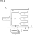
- FIG. 2 is a block diagram showing a configuration of the control system 100 according to the embodiment.
- the control system 100 includes an in-vehicle network 3, the imaging device 4, a plurality of airbag devices 5, an alarm device 6, and the ECU 10.
- the ECU 10 is an example of the object joint detection device.
- the object joint detection device may include the imaging device 4 in addition to the ECU 10.
- the plurality of airbag devices 5 is provided corresponding to each of the plurality of seats 2.
- the airbag device 5 protects an occupant seated on the seat 2 from impact by deploying an airbag in the event of collision or the like of the vehicle 1.
- the alarm device 6 includes, for example, a warning light, a speaker, and the like, and issues an alarm to the occupant by light or sound.
- the alarm device 6 may include a communication part and transmit predetermined alarm information to a portable terminal such as a smartphone carried by the occupant.
- the ECU 10 includes, for example, a central processing unit (CPU) 11, a solid state drive (SSD) 12, a read only memory (ROM) 13, and a random access memory (RAM) 14.
- the CPU 11 realizes a function as an object joint detection device by executing a program installed and stored in a nonvolatile storage device such as the ROM 13.
- the RAM 14 temporarily stores various types of data used in calculation in the CPU 11.
- the SSD 12 is a rewritable nonvolatile storage device, and can store data even when the power supply of the ECU 10 is turned off.
- the CPU 11, the ROM 13, the RAM 14, and the like can be integrated in the same package.
- the ECU 10 may have a configuration in which another logical operation processor such as a digital signal processor (DSP), a logic circuit, or the like is used instead of the CPU 11.
- DSP digital signal processor
- a hard disk drive (HDD) may be provided instead of the SSD 12, or the SSD 12 or the HDD may be provided separately from the ECU 10.
- the ECU 10 realizes various control functions of the vehicle 1 in addition to the function as the object joint detection device.
- the ECU 10 can control the airbag device 5 and the alarm device 6 by sending a control signal via the in-vehicle network 3.
- the ECU 10 can execute control of a brake system, control of a steering system, and the like.
- the ECU 10 can acquire an image of the vehicle interior captured by the imaging device 4 from the imaging device 4 via an output line.
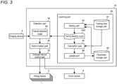
- FIG. 3 is a block diagram showing a functional configuration of the ECU 10.
- the ECU 10 includes a detection part 30, a determination part 40, an onboard device control part 50, and a learning part 60.
- the function of each part included in the ECU 10 is realized by the CPU 11 executing a program stored in the ROM 13. Note that these configurations may be implemented by a hardware circuit.
- the detection part 30 executes the object position detection processing by using a trained detection model 64 obtained by machine learning to be described later.
- the trained detection model 64 inputs an image and outputs an estimated position of each of a predetermined number of objects included in the acquired image.
- the trained detection model is artificial intelligence (AI) such as a trained neural network, and is, for example, a trained model (estimation model) such as a deep neural network (DNN) or a convolutional neural network (CNN).
- AI artificial intelligence
- DNN deep neural network
- CNN convolutional neural network
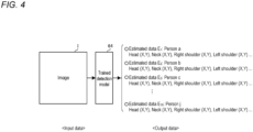
- FIG. 4 is a diagram for explaining the object position detection processing using the trained detection model 64.
- FIG. 5 is a diagram showing an example of a detection image LI as input data to the trained detection model 64.
- the trained detection model 64 inputs an image I obtained by imaging a plurality of obj ects, and outputs estimated data including an estimated position of each joint included in each of the plurality of objects in the image I. That is, in the trained detection model 64, the image is not required to be searched over the entire region, and the type and position of a target and each feature point are directly estimated.
- 10 objects are included in a detection image LI as the input data. Note that, in the detection image LI shown in FIG. 5 , only a person A, a person B, and a person C are exemplified.
- the estimated data output by the trained detection model 64 is the following information. That is, in a case where the detection image LI is input to the trained detection model 64, the estimated data output by the trained detection model 64 is information including recognition (ID) of each object and the estimated position of each joint of each object as shown in FIGS. 4 and 5 .
- the estimated data of the person A is the recognition information (ID) of the object and the estimated position (coordinates) of each joint such as a head (X,Y), a neck (X,Y), a right shoulder (X,Y), or a left shoulder (X,Y).
- the detection part 30 outputs the estimated position of each joint of each detected object to the determination part 40.
- the determination part 40 determines which object is present at which position in front of the vehicle 1 and in what posture (pose) on the basis of the estimated position of each joint of each object detected by the detection part 30.
- the determination part 40 outputs the determination result to the onboard device control part 50.
- the onboard device control part 50 controls various devices mounted on the vehicle 1.
- the onboard device control part 50 individually controls a brake, an accelerator, an airbag device, and the like (an example of the in-vehicle device) on the basis of the determination result in the determination part 40.
- the learning part 60 executes learning processing of a training detection model 640, and generates the trained detection model 64 by optimizing a network parameter (hereinafter, also simply referred to as a "parameter") of the training detection model 640.
- the learning part 60 includes a training data storage part 61, a parameter storage part 62, a setting part 63, the training detection model 640, a calculation part 65, and an update part 66.
- the training data storage part 61 stores a plurality of pieces of training data including a training image obtained by imaging a predetermined number of objects and correct answer data (teacher data) for each object defined in the training image.
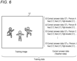
- FIG. 6 is a diagram showing an outline of the training data used for learning of the training detection model 640.
- the training image LI as input data of the training detection model 640 is an image acquired by imaging a plurality of objects. Therefore, the training image LI is an image including 10 objects (three persons are exemplified in FIG. 6 ) as subjects.
- the correct answer data is defined as an ID (recognition information such as the "person A”) indicating what each of the plurality of objects is on the training image LI and a correct answer position (X,Y) of each joint of each object.
- ID recognition information
- X,Y correct answer position
- the training data includes the training image LI including 10 objects as input data and correct answer data of each object on the training image LI.
- the training data is prepared as much as necessary for machine learning of the training detection model 640.
- the parameter storage part 62 stores a network parameter set in the training detection model 640.
- the setting part 63 sets the training image and the parameter in the training detection model 640.
- the calculation part 65 executes adopted error calculation processing and adopted total sum error group determination processing to be described later.
- the update part 66 executes parameter optimization processing to be described later. Note that the calculation part 65 is an example of a parameter optimization part.
- the learning processing of the training detection model 640 executed by the learning part 60 includes the adopted total sum error group determination processing and the parameter optimization processing.
- the adopted total sum error group determination processing is processing of efficiently determining an adopted total sum error group used for a loss function of the machine learning of the training detection model 640 by associating the estimated position and the correct answer position in an optional order.
- the parameter optimization processing is processing of minimizing the loss function defined by using the adopted total sum error group and optimizing the network parameter of the training detection model 640. Each piece of the processing will be described below.
- FIGS. 7 , 8 , and 9 are diagrams for explaining the adopted total sum error group determination processing.
- the training image LI is input to the training detection model 640, and a plurality of pieces of estimated data E 1 to E 10 are output as estimated data.
- An optional one among the plurality of pieces of estimated data E 1 to E 10 for example, the estimated data E 1 of a person a is selected. For each joint included in the selected estimated data E 1 , an error between an estimated position thereof and an estimated position of the corresponding joint included in correct answer data GT 1 of the person A is calculated, and the total sum of the obtained error for each joint is calculated as a total sum error ea T1 . Similarly, the total sum error calculation processing of calculating a total sum error ea T2 to a total sum error ea T10 between the selected estimated data E 1 and each of correct answer data GT 2 to correct answer data GT 10 of the plurality of remaining persons is executed.
- the smallest total sum error (minimum total sum error) is determined as an adopted total sum error ET 1 used for learning. Note that the example illustrated in FIG. 7 shows a case where the total sum error ea 1 is the adopted total sum error ET 1 (minimum total sum error).
- an optional one among the plurality of pieces of estimated data E 2 to E 10 of the plurality of remaining persons, for example, the estimated data E 2 is selected.
- an error between an estimated position thereof and an estimated position of the corresponding joint included in, for example, correct answer data GT 2 of the person B is calculated, and the total sum of the obtained error for each joint is calculated as a total sum error eb T1 .
- the total sum error calculation processing of calculating a total sum error eb T2 to a total sum error eb T9 between the selected estimated data E 2 and each of the correct answer data GT 3 to the correct answer data GT 10 of the plurality of remaining persons is executed.
- the minimum total sum error is determined as an adopted total sum error ET 2 used for learning. Note that the example illustrated in FIG. 7 shows a case where the total sum error eb T2 is the adopted total sum error ET 2 (minimum total sum error).
- an optional one among the plurality of pieces of estimated data E 3 to E 10 of the plurality of remaining persons, for example, the estimated data E 3 is selected.
- an error between an estimated position thereof and an estimated position of the corresponding joint included in, for example, correct answer data GT 2 of the person B is calculated, and the total sum of the obtained error for each joint is calculated as a total sum error ec T1 .
- the total sum error calculation processing of calculating a total sum error ec T1 to a total sum error ec T8 between the selected estimated data E 2 and each of the correct answer data GT 4 to the correct answer data GT 10 of the plurality of remaining persons is executed.
- the minimum total sum error is determined as an adopted total sum error ET 3 used for learning of the object C.
- the example illustrated in FIG. 9 shows a case where the total sum error ec T1 is the adopted total sum error ET 3 (minimum total sum error).
- the determined adopted total sum error ET 1 to ET 10 are referred to as an "adopted total sum error group".
- a loss function L 1 used in the learning processing using a training image LI 1 and the training data including the correct answer data associated with the training image LI can be defined by using the adopted total sum error group.
- the loss function L 1 can be defined by the sum of the adopted total sum errors ET 1 to ET 10 constituting the adopted total sum error group. Further, if necessary, the loss function L1 can be set as a weighted linear sum of the adopted total sum errors ET 1 to ET 10 .
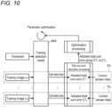
- FIG. 10 is a diagram for explaining an outline of the learning processing including the adopted total sum error group determination processing and the parameter optimization processing.
- the calculation part 65 executes the adopted total sum error group determination processing for each training image and determines the loss function for each training image. Note that, in FIG. 10 , the adopted total sum error group determination processing EI n corresponds to the training image LI n .
- the update part 66 sequentially updates the network parameter by using the training data and the corresponding loss function, and executes the parameter optimization processing.
- a method of the parameter optimization processing a general method such as a gradient descent method, a stochastic gradient descent method, or an error back-propagation method can be adopted.
- the learning part 60 stores the optimized parameter in the parameter storage part 62.
- the learning part 60 outputs the optimized parameter to the detection part 30.
- FIG. 11 is a flowchart showing an example of a procedure of the learning processing executed by the ECU 10.
- the setting part 63 reads the training data from the training data storage part 61 (step S101).
- the setting part 63 reads the parameter from the parameter storage part 62 (step S102), and sets the read parameter in the training detection model 640 (step S103).
- step S104 the training image of the training data read in step S101 is input to the training detection model 640 (step S104).
- the calculation part 65 acquires each piece of estimated data output from the training detection model 640 (step S105).
- the calculation part 65 selects predetermined (optional) estimated data among the plurality of pieces of acquired estimated data (step S106).
- the calculation part 65 executes the total sum error calculation processing between each of the plurality of pieces of correct answer data of the training data read in step S101 and the selected estimated data (step S107). As a result, the total sum error for each of the plurality of objects is calculated.
- the calculation part 65 determines the minimum total sum error among the plurality of total sum errors calculated in step S107 as the adopted total sum error for the object corresponding to the selected estimated data (step S108).
- the calculation part 65 determines whether or not there is an object for which the adopted total sum error has not been determined (step S109). In a case where it is determined that there is a remaining object (Yes in step S109), the calculation part 65 repeatedly executes the processing of steps S106 to S108. On the other hand, when it is determined that there is no remaining object (No in step S 109), the calculation part 65 determines whether or not the processing has been executed for all the training images (step S110).
- the update part 66 executes the parameter optimization processing using the adopted total sum error group (loss function) for each image (step S111).
- the processing of steps S104 to S109 is repeatedly executed for the remaining training images.
- the object joint detection device includes the detection model 64, the learning part 60, and the calculation part 65 as the parameter optimization part.
- the detection model 64 outputs the estimated data including the estimated position of each feature point included in each of the plurality of objects in the input image.
- the learning part 60 executes the detection model 64 and the machine learning of the detection model 64.
- the calculation part 65 optimizes the parameter for estimating a position of each feature point of an optional object among the objects of the plurality of pieces of estimated data output from the detection model 64 to which the training image obtained by imaging the plurality of objects is input.
- the detection model 64 outputs the estimated data including the estimated position for each feature point included in each of the plurality of objects in a newly input image by using the parameter optimized by the calculation part 65.
- a target and type and position of each feature point can be directly estimated without requiring to have the image divided into regions and search the entire region of the image. Therefore, only the minimum necessary calculation needs to be executed for detecting a plurality of objects of which the number is determined in advance from the image, and highly accurate position detection can be realized while the calculation load is reduced.
- the learning part 60 includes the training data storage part 61 and the calculation part 65.
- the training data storage part 61 stores the training image obtained by imaging the plurality of objects in association with the correct answer data for each object including the correct answer position of each feature point included in each object in the training image.
- the calculation part 65 calculates, for each object, the total sum error that is the total sum of errors between the estimated position and the correct answer position for each feature point of the optional object by using the estimated data of the optional object among the objects of the plurality of pieces of estimated data output from the training detection model 640 to which the training image is input and using the correct answer data for each object.
- the calculation part 65 associates an object corresponding to the minimum total sum error among the total sum errors for each object with the optional object, and determines each of the minimum total sum errors as the adopted total sum error group used for the parameter optimization processing of the detection model, the minimum total sum error being used to make each of the objects of the plurality of pieces of correct answer data correspond to any one of the objects of the plurality of pieces of estimated data.
- the estimated position of the feature point of the object to be detected is associated in an optional order with the correct answer position of the feature point defined in advance for each object.
- efficient learning that does not depend on the correct answer order can be realized for the detection model that detects a predetermined number of the plurality of objects from the image.
- the calculation part 65 excludes the correct answer position associated with the estimated position from the association with the correct answer position for other estimated positions. That is, in the learning processing of the training detection model 640, the learning part 60 assigns, to any one of the plurality of estimated positions output by the training detection model 640, the correct answer position that is the closest (with the smallest error) from among the plurality of correct answer positions. In addition, in the learning processing of the training detection model 640, the learning part 60 assigns, to any one of the plurality of remaining estimated positions (whose correct answer position has not been assigned) output by the training detection model 640, the correct answer position that is the closest (with the smallest error) from among the plurality of remaining correct answer positions (which have not been assigned to the estimated position).
- the error calculation processing of only an integer sum from 1 to N only needs to be executed.
- the calculation load in the learning processing can be significantly reduced as compared with the conventional art, and the calculation for detecting the object position by an inexpensive arithmetic processing device can be performed.
- the calculation part 65 calculates the error by using the loss function that is the sum of the errors included in the adopted error group.
- the learning part 60 updates the parameter of the training detection model 640 on the basis of the error using the loss function that is the sum of the errors included in the adopted error group.
- the parameter optimization processing in consideration of the correct answer position of each of the plurality of objects in the training image can be executed, and convergence in learning can be improved.
- the object feature point detection device 1 as the object joint detection device has been described as an example in which the object to be detected is a person, and the feature point is a joint of a human body.
- the object to be detected is not limited to a person, and can be various object targets including a moving body such as a robot, a robot arm, and a vehicle.
- the object to be detected is a robot or a robot arm
- a joint, a manipulator portion, or the like of the robot or the like can be used as the feature point.
- the object to be detected is a vehicle
- a headlight, a tail lamp, a door, or the like can be used as the feature point.
- a similar effect can be realized by preparing correct answer data including a correct answer position of each feature point of an object in the training image and executing the above-described learning processing by using the correct answer data.
- the trained detection model 64 is applied to the processing of detecting the object included in the image obtained by imaging the front of the vehicle 1 and the position of the object.
- the present invention is not particularly limited to this example.
- the trained detection model 64 can be applied to processing of detecting an object included in an image obtained by imaging the side, the rear, or the like of the vehicle 1 and the position of the object.
- the trained detection model 64 can be applied to processing of detecting a head of a passenger included in an image obtained by imaging the vehicle interior. That is, as long as the number of the plurality of objects included in the image is determined in advance, the positions of the plurality of objects included in the image can be detected by similarly applying the trained detection model 64 even in an image in which any type of subject is imaged.
- the calculation part 65 may make the weight with respect to a width W in the horizontal axis direction and a height H in the vertical axis direction included in each correct answer position and each estimated position larger than the coordinates (X,Y) included in each correct answer position and each estimated position. That is, the size and shape of the bounding box can be adjusted according to a detection target.
- the learning part 60 that executes the learning processing of the training detection model 640 and the detection part 30 including the training detection model 640 that performs the estimation processing are built in the same device.
- the learning part 60 and the detection part 30 can be configured as separate devices.
- the learning part 60 can be realized by a computer on a cloud.
Landscapes
- Engineering & Computer Science (AREA)
- Theoretical Computer Science (AREA)
- Physics & Mathematics (AREA)
- General Physics & Mathematics (AREA)
- Computer Vision & Pattern Recognition (AREA)
- Multimedia (AREA)
- Evolutionary Computation (AREA)
- Computing Systems (AREA)
- Artificial Intelligence (AREA)
- Databases & Information Systems (AREA)
- Health & Medical Sciences (AREA)
- General Health & Medical Sciences (AREA)
- Medical Informatics (AREA)
- Software Systems (AREA)
- Image Analysis (AREA)
- Image Processing (AREA)
Abstract
Description
- An embodiment according to the present invention relate to an object feature point detection device.
- In recent years, various object joint detection techniques for detecting a joint of an object such as a person and a position thereof from a camera image have been proposed. In the conventional object joint detection technique, a camera image is divided, and object joint detection processing is executed for each region. Therefore, the accuracy of position estimation and connection estimation has been difficult to be improved unless the image is finely divided. As a result, a calculation load in the object joint detection becomes generally heavy.
- In an object feature point detection technique such as the object joint detection, it is advantageous if the calculation load can be reduced.
- Patent Literature 1:
JP 2021-86322 A - Therefore, the present invention provides an object feature point detection device that can reduce a calculation load as compared with the conventional art.
- An object feature point detection device according to an embodiment of the present invention includes, as an example, a detection model, a learning part, and a parameter optimization part. The detection model outputs estimated data including an estimated position for each feature point included in each of a plurality of objects in an input image. The learning part executes the detection model and machine learning of the detection model. The parameter optimization part optimizes a parameter configured to estimate a position of each feature point of an optional object among objects of a plurality of pieces of the estimated data output from the detection model to which a training image obtained by imaging a plurality of objects is input. The detection model outputs estimated data including an estimated position for each feature point included in each of a plurality of objects in a newly input image by using a parameter optimized by the parameter optimization part.
- With the above configuration, as an example, a target and type and position of each feature point can be directly estimated without requiring to divide the image into regions and search the entire region of the image. Therefore, only the minimum necessary calculation needs to be executed for detecting a plurality of objects of which the number is determined in advance from the image, and highly accurate position detection can be realized while the calculation load is reduced.
- In the object feature point detection device, the learning part includes: a training data storage part that stores a training image obtained by imaging a plurality of objects in association with correct answer data for each object including a correct answer position for each feature point included in each of the objects in the training image; and a calculation part that is configured to, by using estimated data of an optional object among objects of a plurality of pieces of the estimated data output from the detection model to which the training image is input and using the correct answer data for each object: calculate, for each of the objects, a total sum error that is a total sum of errors between the estimated position and the correct answer position for each feature point of the optional object; associate the object corresponding to a minimum total sum error among the total sum errors of each of the objects with the optional object; and determine each of minimum total sum errors as an adopted total sum error group to be used in parameter optimization processing of the detection model, the minimum total sum error being used to make each of objects of a plurality of pieces of the correct answer data correspond to any one of objects of a plurality of pieces of the estimated data.
- In addition, the estimated position of the feature point of the object to be detected and the correct answer position of the feature point defined in advance for each object are associated with each other in an optional order. As a result, efficient learning that does not depend on the correct answer order can be realized for the detection model that detects a predetermined number of the plurality of objects from the image.
- In the object feature point detection device, the calculation part may exclude an object of correct answer data associated with an object of estimated data from being associated with an object of correct answer data for objects of other pieces of estimated data.
- According to the above configuration, in the determination of the adopted total sum error group, in a case where the number of detection objects used for learning is N, the total sum error calculation processing of an integer sum from 1 to N only needs to be executed. As a result, the calculation load in the learning processing can be significantly reduced as compared with the conventional art, and the calculation for detecting the object position by an inexpensive arithmetic processing device can be performed.
- In the object feature point detection device, the calculation part may calculate an error by using a loss function that is a sum of total sum errors included in the adopted total sum error group, and the learning part may further include an update part that updates, in the optimization processing, the parameter of the detection model on the basis of the total sum error using the loss function.
- With the above configuration, the parameter optimization processing in consideration of the correct answer position of each of the plurality of objects in the training image can be executed, and convergence in learning can be improved.
- In the object feature point detection device, the object may be a person, and the feature point may be a joint point of a human body.
- With the above configuration, the posture of each of the plurality of persons can be detected with high accuracy while the calculation load is reduced.
- An object feature point detection device according to the embodiment of the present invention is, as an example, an object feature point detection device including a detection model that outputs estimated data including an estimated position for each feature point included in each of a plurality of obj ects in an input image, in which the detection model is configured to, by using estimated data of an optional object among objects of a plurality of pieces of the estimated data output from the detection model to which a training image obtained by imaging a plurality of objects is input and using correct answer data for each object including a correct answer position for each feature point included in each of the objects in a training image: calculate, for each of the objects, a total sum error that is a total sum of errors between the estimated position and the correct answer position for each feature point of the optional object; associate the object corresponding to a minimum total sum error among the total sum errors of each of the objects with the optional object; and perform optimization processing of a parameter by using each of minimum total sum errors as an adopted total sum error group, the minimum total sum error being used to make each of objects of a plurality of pieces of the correct answer data correspond to any one of objects of a plurality of pieces of the estimated data.
- Therefore, as an example, the image is not required to be searched over the entire region, and the type and position of each feature point can be directly estimated. Therefore, only the minimum necessary calculation needs to be executed for detecting a plurality of objects of which the number is determined in advance from the image, and highly accurate position detection can be realized while the calculation load is reduced.
-
-
FIG. 1 is a plan view of a vehicle interior of a vehicle on which an object joint detection device according to an embodiment is mounted as viewed from above. -
FIG. 2 is a block diagram showing a configuration of a control system according to the embodiment. -
FIG. 3 is a block diagram showing a functional configuration of an electronic control unit (ECU). -
FIG. 4 is a diagram for explaining an outline of a detection model. -
FIG. 5 is a diagram showing an example of a captured image as input data to the detection model. -
FIG. 6 is a diagram showing an outline of training data used for learning of a training detection model. -
FIG. 7 is a diagram showing an outline of adopted error group determination processing executed in learning of the detection model. -
FIG. 8 is a diagram showing an outline of the adopted error group determination processing executed in learning of the detection model. -
FIG. 9 is a diagram showing an outline of the adopted error group determination processing executed in learning of the detection model. -
FIG. 10 is a diagram showing an outline of learning processing including the adopted error group determination processing and parameter optimization processing. -
FIG. 11 is a flowchart showing an example of a procedure of learning processing executed by the ECU as the object joint detection device. - Hereinafter, modes (hereinafter referred to as "embodiment") for implementing an object feature point detection device according to the present application will be described in detail with reference to the drawings.
- The object feature point detection device according to the embodiment outputs estimated data including an estimated position for each feature point included in each of a plurality of objects in an input image. Here, the "object" is a moving body (vehicle, two-wheeled vehicle, person, animal, robot, robot arm, drone, and the like), a three-dimensional structure, or the like.
- Note that, in the following, in order to make the description specific, a case where the object to be detected is a person (human body) and the feature point of the object is a joint point of the human body, that is, a case where the object feature point detection device is an object joint detection device is taken as an example.
- Note that, according to the embodiment, the object feature point detection device according to the present application is not limited to the object joint detection device. In addition, in each of the following embodiments, the same parts are denoted by the same reference numerals, and redundant description will be omitted.
-
FIG. 1 is a plan view of a vehicle interior of avehicle 1 on which the object joint detection device according to the embodiment is mounted as viewed from above. -
FIG. 1 shows an example of the vehicle interior of thevehicle 1 having a riding capacity of five people. The vehicle interior of thevehicle 1 is provided with a plurality ofseats 2. Adriver seat 2a and apassenger seat 2b are provided on the front side in the vehicle interior, and a plurality ofrear seats 2c to 2e are provided on the rear side. Therear seat 2c is provided behind thedriver seat 2a, therear seat 2d is provided behind thepassenger seat 2b, and therear seat 2e is provided between therear seat 2c and therear seat 2d. - An
imaging device 4 is provided on the front side of the vehicle interior. Theimaging device 4 incorporates an imaging element such as a charge coupled device (CCD) or a CMOS image sensor (CIS), and outputs an image captured by the imaging element to an ECU 10 (seeFIG. 2 ) to be described later. Theimaging device 4 images, for example, the front of thevehicle 1 at a predetermined frame rate. - For example, any type of camera such as a monocular camera, a stereo camera, a visible light camera, an infrared camera, or a time-of-flight (TOF) distance image camera can be adopted as the
imaging device 4. Note that, among these cameras, the infrared camera is effective in that halation is less likely to occur even in a situation where the outside of the vehicle is bright, and an occupant can be captured to some extent even in a situation where the inside of the vehicle is dark. - The
vehicle 1 is provided with acontrol system 100 including the object joint detection device. A configuration of thecontrol system 100 will be described with reference toFIG. 2. FIG. 2 is a block diagram showing a configuration of thecontrol system 100 according to the embodiment. - As shown in
FIG. 2 , thecontrol system 100 includes an in-vehicle network 3, theimaging device 4, a plurality ofairbag devices 5, analarm device 6, and theECU 10. TheECU 10 is an example of the object joint detection device. The object joint detection device may include theimaging device 4 in addition to theECU 10. - The plurality of
airbag devices 5 is provided corresponding to each of the plurality ofseats 2. Theairbag device 5 protects an occupant seated on theseat 2 from impact by deploying an airbag in the event of collision or the like of thevehicle 1. Thealarm device 6 includes, for example, a warning light, a speaker, and the like, and issues an alarm to the occupant by light or sound. Note that thealarm device 6 may include a communication part and transmit predetermined alarm information to a portable terminal such as a smartphone carried by the occupant. - The
ECU 10 includes, for example, a central processing unit (CPU) 11, a solid state drive (SSD) 12, a read only memory (ROM) 13, and a random access memory (RAM) 14. TheCPU 11 realizes a function as an object joint detection device by executing a program installed and stored in a nonvolatile storage device such as theROM 13. TheRAM 14 temporarily stores various types of data used in calculation in theCPU 11. TheSSD 12 is a rewritable nonvolatile storage device, and can store data even when the power supply of theECU 10 is turned off. TheCPU 11, theROM 13, theRAM 14, and the like can be integrated in the same package. TheECU 10 may have a configuration in which another logical operation processor such as a digital signal processor (DSP), a logic circuit, or the like is used instead of theCPU 11. A hard disk drive (HDD) may be provided instead of theSSD 12, or theSSD 12 or the HDD may be provided separately from theECU 10. - The
ECU 10 realizes various control functions of thevehicle 1 in addition to the function as the object joint detection device. For example, theECU 10 can control theairbag device 5 and thealarm device 6 by sending a control signal via the in-vehicle network 3. In addition, theECU 10 can execute control of a brake system, control of a steering system, and the like. Further, theECU 10 can acquire an image of the vehicle interior captured by theimaging device 4 from theimaging device 4 via an output line. - Next, a functional configuration of the
ECU 10 will be described with reference toFIG. 3. FIG. 3 is a block diagram showing a functional configuration of theECU 10. - As shown in
FIG. 3 , theECU 10 includes adetection part 30, adetermination part 40, an onboarddevice control part 50, and alearning part 60. The function of each part included in theECU 10 is realized by theCPU 11 executing a program stored in theROM 13. Note that these configurations may be implemented by a hardware circuit. - The
detection part 30 executes the object position detection processing by using a traineddetection model 64 obtained by machine learning to be described later. - The trained
detection model 64 inputs an image and outputs an estimated position of each of a predetermined number of objects included in the acquired image. Specifically, the trained detection model is artificial intelligence (AI) such as a trained neural network, and is, for example, a trained model (estimation model) such as a deep neural network (DNN) or a convolutional neural network (CNN). -
FIG. 4 is a diagram for explaining the object position detection processing using the traineddetection model 64.FIG. 5 is a diagram showing an example of a detection image LI as input data to the traineddetection model 64. - As illustrated in
FIG. 4 , the traineddetection model 64 inputs an image I obtained by imaging a plurality of obj ects, and outputs estimated data including an estimated position of each joint included in each of the plurality of objects in the image I. That is, in the traineddetection model 64, the image is not required to be searched over the entire region, and the type and position of a target and each feature point are directly estimated. Hereinafter, in order to make the description specific, it is assumed that 10 objects are included in a detection image LI as the input data. Note that, in the detection image LI shown inFIG. 5 , only a person A, a person B, and a person C are exemplified. - Here, the estimated data output by the trained
detection model 64 is the following information. That is, in a case where the detection image LI is input to the traineddetection model 64, the estimated data output by the traineddetection model 64 is information including recognition (ID) of each object and the estimated position of each joint of each object as shown inFIGS. 4 and5 . For example, the estimated data of the person A is the recognition information (ID) of the object and the estimated position (coordinates) of each joint such as a head (X,Y), a neck (X,Y), a right shoulder (X,Y), or a left shoulder (X,Y). Thedetection part 30 outputs the estimated position of each joint of each detected object to thedetermination part 40. - The
determination part 40 determines which object is present at which position in front of thevehicle 1 and in what posture (pose) on the basis of the estimated position of each joint of each object detected by thedetection part 30. Thedetermination part 40 outputs the determination result to the onboarddevice control part 50. - The onboard
device control part 50 controls various devices mounted on thevehicle 1. As an example, the onboarddevice control part 50 individually controls a brake, an accelerator, an airbag device, and the like (an example of the in-vehicle device) on the basis of the determination result in thedetermination part 40. - The learning
part 60 executes learning processing of atraining detection model 640, and generates the traineddetection model 64 by optimizing a network parameter (hereinafter, also simply referred to as a "parameter") of thetraining detection model 640. The learningpart 60 includes a trainingdata storage part 61, aparameter storage part 62, a settingpart 63, thetraining detection model 640, acalculation part 65, and anupdate part 66. - The training
data storage part 61 stores a plurality of pieces of training data including a training image obtained by imaging a predetermined number of objects and correct answer data (teacher data) for each object defined in the training image. -
FIG. 6 is a diagram showing an outline of the training data used for learning of thetraining detection model 640. The training image LI as input data of thetraining detection model 640 is an image acquired by imaging a plurality of objects. Therefore, the training image LI is an image including 10 objects (three persons are exemplified inFIG. 6 ) as subjects. - In addition, the correct answer data is defined as an ID (recognition information such as the "person A") indicating what each of the plurality of objects is on the training image LI and a correct answer position (X,Y) of each joint of each object. For example, as illustrated in
FIG. 6 , in the correct answer data of the person A on the training image LI, the head (X,Y), the neck (X,Y), the right shoulder (X,Y), the left shoulder (X,Y), and the like are defined as those corresponding to the correct answer positions of the respective joints of the person A. The training data includes the training image LI including 10 objects as input data and correct answer data of each object on the training image LI. The training data is prepared as much as necessary for machine learning of thetraining detection model 640. - The
parameter storage part 62 stores a network parameter set in thetraining detection model 640. The settingpart 63 sets the training image and the parameter in thetraining detection model 640. Thecalculation part 65 executes adopted error calculation processing and adopted total sum error group determination processing to be described later. Theupdate part 66 executes parameter optimization processing to be described later. Note that thecalculation part 65 is an example of a parameter optimization part. - The learning processing of the
training detection model 640 executed by the learningpart 60 includes the adopted total sum error group determination processing and the parameter optimization processing. Here, the adopted total sum error group determination processing is processing of efficiently determining an adopted total sum error group used for a loss function of the machine learning of thetraining detection model 640 by associating the estimated position and the correct answer position in an optional order. The parameter optimization processing is processing of minimizing the loss function defined by using the adopted total sum error group and optimizing the network parameter of thetraining detection model 640. Each piece of the processing will be described below. -
FIGS. 7 ,8 , and9 are diagrams for explaining the adopted total sum error group determination processing. - First, as shown in
FIG. 7 , the training image LI is input to thetraining detection model 640, and a plurality of pieces of estimated data E1 to E10 are output as estimated data. - An optional one among the plurality of pieces of estimated data E1 to E10, for example, the estimated data E1 of a person a is selected. For each joint included in the selected estimated data E1, an error between an estimated position thereof and an estimated position of the corresponding joint included in correct answer data GT1 of the person A is calculated, and the total sum of the obtained error for each joint is calculated as a total sum error eaT1. Similarly, the total sum error calculation processing of calculating a total sum error eaT2 to a total sum error eaT10 between the selected estimated data E1 and each of correct answer data GT2 to correct answer data GT10 of the plurality of remaining persons is executed.
- Among the total sum error eaT1 to the total sum error eaT10 acquired by the above calculation, the smallest total sum error (minimum total sum error) is determined as an adopted total sum error ET1 used for learning. Note that the example illustrated in
FIG. 7 shows a case where the total sum error ea1 is the adopted total sum error ET1 (minimum total sum error). - Next, as shown in
FIG. 8 , an optional one among the plurality of pieces of estimated data E2 to E10 of the plurality of remaining persons, for example, the estimated data E2 is selected. For each joint included in the selected estimated data E2, an error between an estimated position thereof and an estimated position of the corresponding joint included in, for example, correct answer data GT2 of the person B is calculated, and the total sum of the obtained error for each joint is calculated as a total sum error ebT1. Similarly, the total sum error calculation processing of calculating a total sum error ebT2 to a total sum error ebT9 between the selected estimated data E2 and each of the correct answer data GT3 to the correct answer data GT10 of the plurality of remaining persons is executed. - Among the total sum error ebT1 to the total sum error ebT9 that are calculated, the minimum total sum error is determined as an adopted total sum error ET2 used for learning. Note that the example illustrated in
FIG. 7 shows a case where the total sum error ebT2 is the adopted total sum error ET2 (minimum total sum error). - Next, as shown in
FIG. 9 , an optional one among the plurality of pieces of estimated data E3 to E10 of the plurality of remaining persons, for example, the estimated data E3 is selected. For each joint included in the selected estimated data E3, an error between an estimated position thereof and an estimated position of the corresponding joint included in, for example, correct answer data GT2 of the person B is calculated, and the total sum of the obtained error for each joint is calculated as a total sum error ecT1. Similarly, the total sum error calculation processing of calculating a total sum error ecT1 to a total sum error ecT8 between the selected estimated data E2 and each of the correct answer data GT4 to the correct answer data GT10 of the plurality of remaining persons is executed. - Among the total sum error ecT1 to the total sum error ecT8 that are calculated, the minimum total sum error is determined as an adopted total sum error ET3 used for learning of the object C. Note that the example illustrated in
FIG. 9 shows a case where the total sum error ecT1 is the adopted total sum error ET3 (minimum total sum error). - Thereafter, similar processing is executed for the remaining objects, and the adopted total sum errors ET1 to ET10 used for learning of each object are determined. As a result, 10 times of the total sum error calculation processing for calculating the total sum error ea1 to the sum error ea10 are executed.
- In the present embodiment, the determined adopted total sum error ET1 to ET10 are referred to as an "adopted total sum error group". A loss function L1 used in the learning processing using a training image LI1 and the training data including the correct answer data associated with the training image LI can be defined by using the adopted total sum error group.
- For example, the loss function L1 can be defined by the sum of the adopted total sum errors ET1 to ET10 constituting the adopted total sum error group. Further, if necessary, the loss function L1 can be set as a weighted linear sum of the adopted total sum errors ET1 to ET10.
- In the adopted total sum error group determination processing described above, in a case where the number of objects to be learned is 10 as described above, the total sum error calculation processing necessary until the adopted total sum errors for all the objects are determined is 10 + 9 + 8 + 7 + 6 + 5 + 4 + 3 + 2 + 1 = 55 times. Furthermore, for example, in a case where the number of objects to be learned is N, the total sum error calculation processing necessary until the adopted total sum errors for all the objects are determined is N(N + 1)/2 times.
-
FIG. 10 is a diagram for explaining an outline of the learning processing including the adopted total sum error group determination processing and the parameter optimization processing. - As shown in
FIG. 10 , thecalculation part 65 executes the adopted total sum error group determination processing for each training image and determines the loss function for each training image. Note that, inFIG. 10 , the adopted total sum error group determination processing EIn corresponds to the training image LIn. - The
update part 66 sequentially updates the network parameter by using the training data and the corresponding loss function, and executes the parameter optimization processing. As a method of the parameter optimization processing, a general method such as a gradient descent method, a stochastic gradient descent method, or an error back-propagation method can be adopted. - The learning
part 60 stores the optimized parameter in theparameter storage part 62. The learningpart 60 outputs the optimized parameter to thedetection part 30. -
FIG. 11 is a flowchart showing an example of a procedure of the learning processing executed by theECU 10. - As shown in
FIG. 11 , the settingpart 63 reads the training data from the training data storage part 61 (step S101). - Subsequently, the setting
part 63 reads the parameter from the parameter storage part 62 (step S102), and sets the read parameter in the training detection model 640 (step S103). - Subsequently, the training image of the training data read in step S101 is input to the training detection model 640 (step S104).
- The
calculation part 65 acquires each piece of estimated data output from the training detection model 640 (step S105). - The
calculation part 65 selects predetermined (optional) estimated data among the plurality of pieces of acquired estimated data (step S106). - The
calculation part 65 executes the total sum error calculation processing between each of the plurality of pieces of correct answer data of the training data read in step S101 and the selected estimated data (step S107). As a result, the total sum error for each of the plurality of objects is calculated. - The
calculation part 65 determines the minimum total sum error among the plurality of total sum errors calculated in step S107 as the adopted total sum error for the object corresponding to the selected estimated data (step S108). - The
calculation part 65 determines whether or not there is an object for which the adopted total sum error has not been determined (step S109). In a case where it is determined that there is a remaining object (Yes in step S109), thecalculation part 65 repeatedly executes the processing of steps S106 to S108. On the other hand, when it is determined that there is no remaining object (No in step S 109), thecalculation part 65 determines whether or not the processing has been executed for all the training images (step S110). - In a case where the
calculation part 65 determines that the processing has been executed for all the training images, theupdate part 66 executes the parameter optimization processing using the adopted total sum error group (loss function) for each image (step S111). On the other hand, in a case where thecalculation part 65 determines that the processing has not been executed for all the training images, the processing of steps S104 to S109 is repeatedly executed for the remaining training images. - The object joint detection device according to the embodiment described above includes the
detection model 64, the learningpart 60, and thecalculation part 65 as the parameter optimization part. Thedetection model 64 outputs the estimated data including the estimated position of each feature point included in each of the plurality of objects in the input image. The learningpart 60 executes thedetection model 64 and the machine learning of thedetection model 64. Thecalculation part 65 optimizes the parameter for estimating a position of each feature point of an optional object among the objects of the plurality of pieces of estimated data output from thedetection model 64 to which the training image obtained by imaging the plurality of objects is input. Thedetection model 64 outputs the estimated data including the estimated position for each feature point included in each of the plurality of objects in a newly input image by using the parameter optimized by thecalculation part 65. - Therefore, as an example, a target and type and position of each feature point can be directly estimated without requiring to have the image divided into regions and search the entire region of the image. Therefore, only the minimum necessary calculation needs to be executed for detecting a plurality of objects of which the number is determined in advance from the image, and highly accurate position detection can be realized while the calculation load is reduced.
- Furthermore, the learning
part 60 includes the trainingdata storage part 61 and thecalculation part 65. The trainingdata storage part 61 stores the training image obtained by imaging the plurality of objects in association with the correct answer data for each object including the correct answer position of each feature point included in each object in the training image. Thecalculation part 65 calculates, for each object, the total sum error that is the total sum of errors between the estimated position and the correct answer position for each feature point of the optional object by using the estimated data of the optional object among the objects of the plurality of pieces of estimated data output from thetraining detection model 640 to which the training image is input and using the correct answer data for each object. Thecalculation part 65 associates an object corresponding to the minimum total sum error among the total sum errors for each object with the optional object, and determines each of the minimum total sum errors as the adopted total sum error group used for the parameter optimization processing of the detection model, the minimum total sum error being used to make each of the objects of the plurality of pieces of correct answer data correspond to any one of the objects of the plurality of pieces of estimated data. - Therefore, the estimated position of the feature point of the object to be detected is associated in an optional order with the correct answer position of the feature point defined in advance for each object. As a result, efficient learning that does not depend on the correct answer order can be realized for the detection model that detects a predetermined number of the plurality of objects from the image.
- In addition, the
calculation part 65 excludes the correct answer position associated with the estimated position from the association with the correct answer position for other estimated positions. That is, in the learning processing of thetraining detection model 640, the learningpart 60 assigns, to any one of the plurality of estimated positions output by thetraining detection model 640, the correct answer position that is the closest (with the smallest error) from among the plurality of correct answer positions. In addition, in the learning processing of thetraining detection model 640, the learningpart 60 assigns, to any one of the plurality of remaining estimated positions (whose correct answer position has not been assigned) output by thetraining detection model 640, the correct answer position that is the closest (with the smallest error) from among the plurality of remaining correct answer positions (which have not been assigned to the estimated position). - Therefore, in the determination of the adopted total sum error group, in a case where the number of detection objects used for learning is N, the error calculation processing of only an integer sum from 1 to N only needs to be executed. As a result, the calculation load in the learning processing can be significantly reduced as compared with the conventional art, and the calculation for detecting the object position by an inexpensive arithmetic processing device can be performed.
- The
calculation part 65 calculates the error by using the loss function that is the sum of the errors included in the adopted error group. In the parameter optimization processing, the learningpart 60 updates the parameter of thetraining detection model 640 on the basis of the error using the loss function that is the sum of the errors included in the adopted error group. - Therefore, the parameter optimization processing in consideration of the correct answer position of each of the plurality of objects in the training image can be executed, and convergence in learning can be improved.
- In the above-described embodiment, the object feature
point detection device 1 as the object joint detection device has been described as an example in which the object to be detected is a person, and the feature point is a joint of a human body. However, the object to be detected is not limited to a person, and can be various object targets including a moving body such as a robot, a robot arm, and a vehicle. - For example, in a case where the object to be detected is a robot or a robot arm, a joint, a manipulator portion, or the like of the robot or the like can be used as the feature point. In addition, in a case where the object to be detected is a vehicle, a headlight, a tail lamp, a door, or the like can be used as the feature point. In any case, a similar effect can be realized by preparing correct answer data including a correct answer position of each feature point of an object in the training image and executing the above-described learning processing by using the correct answer data.
- In the above embodiment, as an example, an example has been described in which the trained
detection model 64 is applied to the processing of detecting the object included in the image obtained by imaging the front of thevehicle 1 and the position of the object. However, the present invention is not particularly limited to this example. For example, the traineddetection model 64 can be applied to processing of detecting an object included in an image obtained by imaging the side, the rear, or the like of thevehicle 1 and the position of the object. Furthermore, for example, the traineddetection model 64 can be applied to processing of detecting a head of a passenger included in an image obtained by imaging the vehicle interior. That is, as long as the number of the plurality of objects included in the image is determined in advance, the positions of the plurality of objects included in the image can be detected by similarly applying the traineddetection model 64 even in an image in which any type of subject is imaged. - At the time of executing the error calculation processing, the
calculation part 65 may make the weight with respect to a width W in the horizontal axis direction and a height H in the vertical axis direction included in each correct answer position and each estimated position larger than the coordinates (X,Y) included in each correct answer position and each estimated position. That is, the size and shape of the bounding box can be adjusted according to a detection target. - In the above embodiment, the case has been exemplified where the learning
part 60 that executes the learning processing of thetraining detection model 640 and thedetection part 30 including thetraining detection model 640 that performs the estimation processing are built in the same device. However, the learningpart 60 and thedetection part 30 can be configured as separate devices. Furthermore, for example, the learningpart 60 can be realized by a computer on a cloud. - Although the embodiments of the present invention have been exemplified above, the above-described embodiments and modifications are merely examples, and are not intended to limit the scope of the invention. The above-described embodiments and modifications can be implemented in various other forms, and various omissions, substitutions, combinations, and changes can be made without departing from the gist of the invention. In addition, the configuration and shape of each embodiment and each modification can be partially interchanged.
- 1: Vehicle, 2: Seat, 3: In-vehicle network, 4: Imaging device, 5: Airbag device, 6: Alarm device, 10: ECU, 30: Detection part, 40: Determination part, 50: Onboard device control part, 60: Learning part, 61: Training data storage part, 62: Parameter storage part, 63: Setting part, 64: Trained detection model, 65: Calculation part, 66: Update part, 100: Control system, and 640: Training detection model
Claims (6)
- An object feature point detection device comprising:a detection model that outputs estimated data including an estimated position for each feature point included in each of a plurality of objects in an input image;a learning part that executes machine learning of the detection model; anda parameter optimization part that optimizes a parameter configured to estimate a position of each feature point of an optional object among objects of a plurality of pieces of the estimated data output from the detection model to which a training image obtained by imaging a plurality of objects is input,whereinthe detection model outputs estimated data including an estimated position of each feature point included in each of a plurality of objects in a newly input image by using a parameter optimized by the parameter optimization part.
- The object feature point detection device according to claim 1, wherein the learning part comprises:a training data storage part that stores a training image obtained by imaging a plurality of objects in association with correct answer data for each object including a correct answer position of each feature point included in each of the objects in the training image; anda calculation part that is configured to, by using estimated data of an optional object among objects of a plurality of pieces of the estimated data output from the detection model to which the training image is input and using the correct answer data for each object: calculate, for each of the objects, a total sum error that is a total sum of errors between the estimated position and the correct answer position for each feature point of the optional object; associate the object corresponding to a minimum total sum error among the total sum errors of each of the objects with the optional object; and determine each of minimum total sum errors as an adopted total sum error group to be used in parameter optimization processing of the detection model, the minimum total sum error being used to make each of objects of a plurality of pieces of the correct answer data correspond to any one of objects of a plurality of pieces of the estimated data.
- The object feature point detection device according to claim 2, wherein the calculation part excludes an object of correct answer data associated with an object of estimated data from being associated with an object of correct answer data for objects of other pieces of estimated data.
- The object feature point detection device according to claim 2, whereinthe calculation part calculates an error by using a loss function that is a sum of total sum errors included in the adopted total sum error group, andthe learning part further comprises an update part that updates, in the optimization processing, the parameter of the detection model on a basis of the total sum error using the loss function.
- The object feature point detection device according to claim 1 or 2, wherein the object is a person, and the feature point is a joint point of a human body.
- An object feature point detection device comprising a detection model that outputs estimated data including an estimated position of each feature point included in each of a plurality of objects in an input image,
whereinthe detection model is configured to,by using estimated data of an optional object among objects of a plurality of pieces of estimated data output from the detection model to which a training image obtained by imaging a plurality of object is input and using correct answer data for each object including a correct answer position of each feature point included in each of the objects in a training image: calculate, for each of the objects, a total sum error that is a total sum of errors between the estimated position and the correct answer position of each feature point of the optional object; associate the object corresponding to a minimum total sum error among the total sum errors of each of the objects with the optional object; and perform optimization processing of a parameter by using each of minimum total sum errors as an adopted total sum error group, the minimum total sum error being used to make each of objects of a plurality of pieces of the correct answer data correspond to any one of objects of a plurality of pieces of the estimated data.
Applications Claiming Priority (2)
| Application Number | Priority Date | Filing Date | Title |
|---|---|---|---|
| JP2022058253A JP2023149600A (en) | 2022-03-31 | 2022-03-31 | Object feature point detection device |
| PCT/JP2023/005012 WO2023188908A1 (en) | 2022-03-31 | 2023-02-14 | Object feature point detection device |
Publications (1)
| Publication Number | Publication Date |
|---|---|
| EP4502928A1 true EP4502928A1 (en) | 2025-02-05 |
Family
ID=88201069
Family Applications (1)
| Application Number | Title | Priority Date | Filing Date |
|---|---|---|---|
| EP23778942.5A Withdrawn EP4502928A1 (en) | 2022-03-31 | 2023-02-14 | Object feature point detection device |
Country Status (5)
| Country | Link |
|---|---|
| US (1) | US20250104272A1 (en) |
| EP (1) | EP4502928A1 (en) |
| JP (1) | JP2023149600A (en) |
| CN (1) | CN118922858A (en) |
| WO (1) | WO2023188908A1 (en) |
Family Cites Families (1)
| Publication number | Priority date | Publication date | Assignee | Title |
|---|---|---|---|---|
| JP7422456B2 (en) * | 2019-11-26 | 2024-01-26 | キヤノン株式会社 | Image processing device, image processing method and program |
-
2022
- 2022-03-31 JP JP2022058253A patent/JP2023149600A/en active Pending
-
2023
- 2023-02-14 US US18/726,239 patent/US20250104272A1/en active Pending
- 2023-02-14 EP EP23778942.5A patent/EP4502928A1/en not_active Withdrawn
- 2023-02-14 CN CN202380021361.1A patent/CN118922858A/en active Pending
- 2023-02-14 WO PCT/JP2023/005012 patent/WO2023188908A1/en not_active Ceased
Also Published As
| Publication number | Publication date |
|---|---|
| WO2023188908A1 (en) | 2023-10-05 |
| JP2023149600A (en) | 2023-10-13 |
| CN118922858A (en) | 2024-11-08 |
| US20250104272A1 (en) | 2025-03-27 |
Similar Documents
| Publication | Publication Date | Title |
|---|---|---|
| US11804048B2 (en) | Recognizing the movement intention of a pedestrian from camera images | |
| US11597347B2 (en) | Methods and systems for detecting whether a seat belt is used in a vehicle | |
| US11093801B2 (en) | Object detection device and object detection method | |
| CN113002562B (en) | Vehicle control device and storage medium | |
| KR102921223B1 (en) | Advanced driver assist device and method of detecting object in the same | |
| EP2860664B1 (en) | Face detection apparatus | |
| JP6682833B2 (en) | Database construction system for machine learning of object recognition algorithm | |
| US20240378896A1 (en) | Detected object path prediction for vision-based systems | |
| US7983475B2 (en) | Vehicular actuation system | |
| WO2018009552A1 (en) | System and method for image analysis | |
| JP2020204804A (en) | Image recognition device | |
| JP2020052647A (en) | Object detection device, object detection method, computer program for object detection, and vehicle control system | |
| CN115071702B (en) | Vehicle control device, vehicle control method, and vehicle control computer program | |
| US20240331410A1 (en) | Visual Detection of Hands on Steering Wheel | |
| CN112989915A (en) | System and method for detecting abnormal passenger behavior in an autonomous vehicle | |
| EP4152276A1 (en) | Seat occupancy classification system for a vehicle | |
| US20210383134A1 (en) | Advanced driver assist system and method of detecting object in the same | |
| JP2023104680A (en) | DRIVER MONITOR DEVICE, DRIVER MONITORING METHOD AND COMPUTER PROGRAM FOR DRIVER MONITOR | |
| JP2020204839A (en) | Outside environment recognition device | |
| US20250104272A1 (en) | Object feature point detection device | |
| EP4517663A1 (en) | Method and device for generating a three-dimensional reconstruction of an environment around a vehicle | |
| JP2019074964A (en) | Driving disabled condition prediction device and driving disabled condition prediction system | |
| US12154297B2 (en) | Vehicle and control method thereof | |
| JP2021135957A (en) | Object detection device, object detection method and program | |
| US20220309400A1 (en) | Learning method, learning device, and recording medium |
Legal Events
| Date | Code | Title | Description |
|---|---|---|---|
| STAA | Information on the status of an ep patent application or granted ep patent |
Free format text: STATUS: THE INTERNATIONAL PUBLICATION HAS BEEN MADE |
|
| PUAI | Public reference made under article 153(3) epc to a published international application that has entered the european phase |
Free format text: ORIGINAL CODE: 0009012 |
|
| STAA | Information on the status of an ep patent application or granted ep patent |
Free format text: STATUS: REQUEST FOR EXAMINATION WAS MADE |
|
| 17P | Request for examination filed |
Effective date: 20240625 |
|
| AK | Designated contracting states |
Kind code of ref document: A1 Designated state(s): AL AT BE BG CH CY CZ DE DK EE ES FI FR GB GR HR HU IE IS IT LI LT LU LV MC ME MK MT NL NO PL PT RO RS SE SI SK SM TR |
|
| STAA | Information on the status of an ep patent application or granted ep patent |
Free format text: STATUS: THE APPLICATION HAS BEEN WITHDRAWN |
|
| 18W | Application withdrawn |
Effective date: 20250224 |