EP4502762A1 - Multi-battery electronic device and protection method thereof - Google Patents
Multi-battery electronic device and protection method thereof Download PDFInfo
- Publication number
- EP4502762A1 EP4502762A1 EP24185649.1A EP24185649A EP4502762A1 EP 4502762 A1 EP4502762 A1 EP 4502762A1 EP 24185649 A EP24185649 A EP 24185649A EP 4502762 A1 EP4502762 A1 EP 4502762A1
- Authority
- EP
- European Patent Office
- Prior art keywords
- batteries
- electronic device
- current
- battery
- control circuit
- Prior art date
- Legal status (The legal status is an assumption and is not a legal conclusion. Google has not performed a legal analysis and makes no representation as to the accuracy of the status listed.)
- Pending
Links
Images



Classifications
-
- H—ELECTRICITY
- H02—GENERATION; CONVERSION OR DISTRIBUTION OF ELECTRIC POWER
- H02J—ELECTRIC POWER NETWORKS; CIRCUIT ARRANGEMENTS OR SYSTEMS FOR SUPPLYING OR DISTRIBUTING ELECTRIC POWER; SYSTEMS FOR STORING ELECTRIC ENERGY
- H02J7/00—Circuit arrangements for charging or discharging batteries or for supplying loads from batteries
- H02J7/60—Circuit arrangements for charging or discharging batteries or for supplying loads from batteries including safety or protection arrangements
- H02J7/61—Circuit arrangements for charging or discharging batteries or for supplying loads from batteries including safety or protection arrangements against overcharge
-
- G—PHYSICS
- G06—COMPUTING OR CALCULATING; COUNTING
- G06F—ELECTRIC DIGITAL DATA PROCESSING
- G06F1/00—Details not covered by groups G06F3/00 - G06F13/00 and G06F21/00
- G06F1/26—Power supply means, e.g. regulation thereof
- G06F1/32—Means for saving power
- G06F1/3203—Power management, i.e. event-based initiation of a power-saving mode
- G06F1/3206—Monitoring of events, devices or parameters that trigger a change in power modality
- G06F1/3212—Monitoring battery levels, e.g. power saving mode being initiated when battery voltage goes below a certain level
-
- G—PHYSICS
- G06—COMPUTING OR CALCULATING; COUNTING
- G06F—ELECTRIC DIGITAL DATA PROCESSING
- G06F1/00—Details not covered by groups G06F3/00 - G06F13/00 and G06F21/00
- G06F1/16—Constructional details or arrangements
- G06F1/20—Cooling means
- G06F1/206—Cooling means comprising thermal management
-
- G—PHYSICS
- G06—COMPUTING OR CALCULATING; COUNTING
- G06F—ELECTRIC DIGITAL DATA PROCESSING
- G06F1/00—Details not covered by groups G06F3/00 - G06F13/00 and G06F21/00
- G06F1/26—Power supply means, e.g. regulation thereof
- G06F1/263—Arrangements for using multiple switchable power supplies, e.g. battery and AC
-
- G—PHYSICS
- G06—COMPUTING OR CALCULATING; COUNTING
- G06F—ELECTRIC DIGITAL DATA PROCESSING
- G06F1/00—Details not covered by groups G06F3/00 - G06F13/00 and G06F21/00
- G06F1/26—Power supply means, e.g. regulation thereof
- G06F1/28—Supervision thereof, e.g. detecting power-supply failure by out of limits supervision
-
- G—PHYSICS
- G06—COMPUTING OR CALCULATING; COUNTING
- G06F—ELECTRIC DIGITAL DATA PROCESSING
- G06F1/00—Details not covered by groups G06F3/00 - G06F13/00 and G06F21/00
- G06F1/26—Power supply means, e.g. regulation thereof
- G06F1/32—Means for saving power
- G06F1/3203—Power management, i.e. event-based initiation of a power-saving mode
- G06F1/3234—Power saving characterised by the action undertaken
- G06F1/324—Power saving characterised by the action undertaken by lowering clock frequency
-
- G—PHYSICS
- G06—COMPUTING OR CALCULATING; COUNTING
- G06F—ELECTRIC DIGITAL DATA PROCESSING
- G06F1/00—Details not covered by groups G06F3/00 - G06F13/00 and G06F21/00
- G06F1/26—Power supply means, e.g. regulation thereof
- G06F1/32—Means for saving power
- G06F1/3203—Power management, i.e. event-based initiation of a power-saving mode
- G06F1/3234—Power saving characterised by the action undertaken
- G06F1/3243—Power saving in microcontroller unit
-
- G—PHYSICS
- G06—COMPUTING OR CALCULATING; COUNTING
- G06F—ELECTRIC DIGITAL DATA PROCESSING
- G06F1/00—Details not covered by groups G06F3/00 - G06F13/00 and G06F21/00
- G06F1/26—Power supply means, e.g. regulation thereof
- G06F1/32—Means for saving power
- G06F1/3203—Power management, i.e. event-based initiation of a power-saving mode
- G06F1/3234—Power saving characterised by the action undertaken
- G06F1/3296—Power saving characterised by the action undertaken by lowering the supply or operating voltage
-
- H—ELECTRICITY
- H01—ELECTRIC ELEMENTS
- H01M—PROCESSES OR MEANS, e.g. BATTERIES, FOR THE DIRECT CONVERSION OF CHEMICAL ENERGY INTO ELECTRICAL ENERGY
- H01M10/00—Secondary cells; Manufacture thereof
- H01M10/42—Methods or arrangements for servicing or maintenance of secondary cells or secondary half-cells
- H01M10/4207—Methods or arrangements for servicing or maintenance of secondary cells or secondary half-cells for several batteries or cells simultaneously or sequentially
-
- H—ELECTRICITY
- H01—ELECTRIC ELEMENTS
- H01M—PROCESSES OR MEANS, e.g. BATTERIES, FOR THE DIRECT CONVERSION OF CHEMICAL ENERGY INTO ELECTRICAL ENERGY
- H01M10/00—Secondary cells; Manufacture thereof
- H01M10/42—Methods or arrangements for servicing or maintenance of secondary cells or secondary half-cells
- H01M10/425—Structural combination with electronic components, e.g. electronic circuits integrated to the outside of the casing
- H01M10/4257—Smart batteries, e.g. electronic circuits inside the housing of the cells or batteries
-
- H—ELECTRICITY
- H01—ELECTRIC ELEMENTS
- H01M—PROCESSES OR MEANS, e.g. BATTERIES, FOR THE DIRECT CONVERSION OF CHEMICAL ENERGY INTO ELECTRICAL ENERGY
- H01M10/00—Secondary cells; Manufacture thereof
- H01M10/42—Methods or arrangements for servicing or maintenance of secondary cells or secondary half-cells
- H01M10/44—Methods for charging or discharging
- H01M10/441—Methods for charging or discharging for several batteries or cells simultaneously or sequentially
-
- H—ELECTRICITY
- H02—GENERATION; CONVERSION OR DISTRIBUTION OF ELECTRIC POWER
- H02J—ELECTRIC POWER NETWORKS; CIRCUIT ARRANGEMENTS OR SYSTEMS FOR SUPPLYING OR DISTRIBUTING ELECTRIC POWER; SYSTEMS FOR STORING ELECTRIC ENERGY
- H02J7/00—Circuit arrangements for charging or discharging batteries or for supplying loads from batteries
- H02J7/50—Circuit arrangements for charging or discharging batteries or for supplying loads from batteries acting upon multiple batteries simultaneously or sequentially
-
- H—ELECTRICITY
- H02—GENERATION; CONVERSION OR DISTRIBUTION OF ELECTRIC POWER
- H02J—ELECTRIC POWER NETWORKS; CIRCUIT ARRANGEMENTS OR SYSTEMS FOR SUPPLYING OR DISTRIBUTING ELECTRIC POWER; SYSTEMS FOR STORING ELECTRIC ENERGY
- H02J7/00—Circuit arrangements for charging or discharging batteries or for supplying loads from batteries
- H02J7/50—Circuit arrangements for charging or discharging batteries or for supplying loads from batteries acting upon multiple batteries simultaneously or sequentially
- H02J7/52—Circuit arrangements for charging or discharging batteries or for supplying loads from batteries acting upon multiple batteries simultaneously or sequentially for charge balancing, e.g. equalisation of charge between batteries
- H02J7/56—Active balancing, e.g. using capacitor-based, inductor-based or DC-DC converters
-
- H—ELECTRICITY
- H02—GENERATION; CONVERSION OR DISTRIBUTION OF ELECTRIC POWER
- H02J—ELECTRIC POWER NETWORKS; CIRCUIT ARRANGEMENTS OR SYSTEMS FOR SUPPLYING OR DISTRIBUTING ELECTRIC POWER; SYSTEMS FOR STORING ELECTRIC ENERGY
- H02J7/00—Circuit arrangements for charging or discharging batteries or for supplying loads from batteries
- H02J7/50—Circuit arrangements for charging or discharging batteries or for supplying loads from batteries acting upon multiple batteries simultaneously or sequentially
- H02J7/575—Parallel/serial switching of connection of batteries to charge or load circuit
-
- H—ELECTRICITY
- H02—GENERATION; CONVERSION OR DISTRIBUTION OF ELECTRIC POWER
- H02J—ELECTRIC POWER NETWORKS; CIRCUIT ARRANGEMENTS OR SYSTEMS FOR SUPPLYING OR DISTRIBUTING ELECTRIC POWER; SYSTEMS FOR STORING ELECTRIC ENERGY
- H02J7/00—Circuit arrangements for charging or discharging batteries or for supplying loads from batteries
- H02J7/60—Circuit arrangements for charging or discharging batteries or for supplying loads from batteries including safety or protection arrangements
- H02J7/63—Circuit arrangements for charging or discharging batteries or for supplying loads from batteries including safety or protection arrangements against overdischarge
-
- H—ELECTRICITY
- H02—GENERATION; CONVERSION OR DISTRIBUTION OF ELECTRIC POWER
- H02J—ELECTRIC POWER NETWORKS; CIRCUIT ARRANGEMENTS OR SYSTEMS FOR SUPPLYING OR DISTRIBUTING ELECTRIC POWER; SYSTEMS FOR STORING ELECTRIC ENERGY
- H02J7/00—Circuit arrangements for charging or discharging batteries or for supplying loads from batteries
- H02J7/60—Circuit arrangements for charging or discharging batteries or for supplying loads from batteries including safety or protection arrangements
- H02J7/65—Circuit arrangements for charging or discharging batteries or for supplying loads from batteries including safety or protection arrangements against overtemperature
-
- H—ELECTRICITY
- H02—GENERATION; CONVERSION OR DISTRIBUTION OF ELECTRIC POWER
- H02J—ELECTRIC POWER NETWORKS; CIRCUIT ARRANGEMENTS OR SYSTEMS FOR SUPPLYING OR DISTRIBUTING ELECTRIC POWER; SYSTEMS FOR STORING ELECTRIC ENERGY
- H02J7/00—Circuit arrangements for charging or discharging batteries or for supplying loads from batteries
- H02J7/80—Circuit arrangements for charging or discharging batteries or for supplying loads from batteries including monitoring or indicating arrangements
-
- H—ELECTRICITY
- H02—GENERATION; CONVERSION OR DISTRIBUTION OF ELECTRIC POWER
- H02J—ELECTRIC POWER NETWORKS; CIRCUIT ARRANGEMENTS OR SYSTEMS FOR SUPPLYING OR DISTRIBUTING ELECTRIC POWER; SYSTEMS FOR STORING ELECTRIC ENERGY
- H02J7/00—Circuit arrangements for charging or discharging batteries or for supplying loads from batteries
- H02J7/80—Circuit arrangements for charging or discharging batteries or for supplying loads from batteries including monitoring or indicating arrangements
- H02J7/82—Control of state of charge [SOC]
-
- H—ELECTRICITY
- H02—GENERATION; CONVERSION OR DISTRIBUTION OF ELECTRIC POWER
- H02J—ELECTRIC POWER NETWORKS; CIRCUIT ARRANGEMENTS OR SYSTEMS FOR SUPPLYING OR DISTRIBUTING ELECTRIC POWER; SYSTEMS FOR STORING ELECTRIC ENERGY
- H02J7/00—Circuit arrangements for charging or discharging batteries or for supplying loads from batteries
- H02J7/855—Circuit arrangements for charging or discharging batteries or for supplying loads from batteries with circuits adapted for supplying loads from the battery
-
- H—ELECTRICITY
- H02—GENERATION; CONVERSION OR DISTRIBUTION OF ELECTRIC POWER
- H02J—ELECTRIC POWER NETWORKS; CIRCUIT ARRANGEMENTS OR SYSTEMS FOR SUPPLYING OR DISTRIBUTING ELECTRIC POWER; SYSTEMS FOR STORING ELECTRIC ENERGY
- H02J7/00—Circuit arrangements for charging or discharging batteries or for supplying loads from batteries
- H02J7/90—Regulation of charging or discharging current or voltage
- H02J7/92—Regulation of charging or discharging current or voltage with prioritisation of loads or sources
-
- H—ELECTRICITY
- H02—GENERATION; CONVERSION OR DISTRIBUTION OF ELECTRIC POWER
- H02J—ELECTRIC POWER NETWORKS; CIRCUIT ARRANGEMENTS OR SYSTEMS FOR SUPPLYING OR DISTRIBUTING ELECTRIC POWER; SYSTEMS FOR STORING ELECTRIC ENERGY
- H02J7/00—Circuit arrangements for charging or discharging batteries or for supplying loads from batteries
- H02J7/90—Regulation of charging or discharging current or voltage
- H02J7/933—Regulation of charging or discharging current or voltage the cycle being controlled or terminated in response to electric parameters
-
- H—ELECTRICITY
- H02—GENERATION; CONVERSION OR DISTRIBUTION OF ELECTRIC POWER
- H02J—ELECTRIC POWER NETWORKS; CIRCUIT ARRANGEMENTS OR SYSTEMS FOR SUPPLYING OR DISTRIBUTING ELECTRIC POWER; SYSTEMS FOR STORING ELECTRIC ENERGY
- H02J7/00—Circuit arrangements for charging or discharging batteries or for supplying loads from batteries
- H02J7/90—Regulation of charging or discharging current or voltage
- H02J7/971—Regulation of charging or discharging current or voltage the charge cycle being controlled or terminated in response to non-electric parameters
- H02J7/975—Regulation of charging or discharging current or voltage the charge cycle being controlled or terminated in response to non-electric parameters in response to temperature
- H02J7/977—Regulation of charging or discharging current or voltage the charge cycle being controlled or terminated in response to non-electric parameters in response to temperature of the battery
-
- H—ELECTRICITY
- H01—ELECTRIC ELEMENTS
- H01M—PROCESSES OR MEANS, e.g. BATTERIES, FOR THE DIRECT CONVERSION OF CHEMICAL ENERGY INTO ELECTRICAL ENERGY
- H01M10/00—Secondary cells; Manufacture thereof
- H01M10/42—Methods or arrangements for servicing or maintenance of secondary cells or secondary half-cells
- H01M10/425—Structural combination with electronic components, e.g. electronic circuits integrated to the outside of the casing
- H01M2010/4271—Battery management systems including electronic circuits, e.g. control of current or voltage to keep battery in healthy state, cell balancing
-
- Y—GENERAL TAGGING OF NEW TECHNOLOGICAL DEVELOPMENTS; GENERAL TAGGING OF CROSS-SECTIONAL TECHNOLOGIES SPANNING OVER SEVERAL SECTIONS OF THE IPC; TECHNICAL SUBJECTS COVERED BY FORMER USPC CROSS-REFERENCE ART COLLECTIONS [XRACs] AND DIGESTS
- Y02—TECHNOLOGIES OR APPLICATIONS FOR MITIGATION OR ADAPTATION AGAINST CLIMATE CHANGE
- Y02E—REDUCTION OF GREENHOUSE GAS [GHG] EMISSIONS, RELATED TO ENERGY GENERATION, TRANSMISSION OR DISTRIBUTION
- Y02E60/00—Enabling technologies; Technologies with a potential or indirect contribution to GHG emissions mitigation
- Y02E60/10—Energy storage using batteries
Definitions
- the present invention relates to an electronic device and a protection method thereof, and more particularly to an electronic device that supports multiple batteries and a protection method thereof.
- a single charger and a single battery are disposed in an interior of a computer device.
- a system power consumption of the computer device can sometimes be as high as 400 watts (W). Since an output power of the single battery is only about 70 watts, the power of the computer device is very likely to be instantaneously interrupted, which may even cause damage to the battery.
- the present invention provides a multi-battery electronic device and a protection method thereof.
- one of the technical aspects adopted by the present invention is to provide a multi-battery electronic device, which includes a plurality of batteries, a plurality of battery detectors, and a control circuit.
- the plurality of battery detectors are connected to the plurality of batteries, respectively.
- the control circuit is configured to detect battery status of the plurality of batteries by the plurality of battery detectors. When the control circuit determines that a current capacity difference between any two of the plurality of batteries is greater than a capacity difference threshold, the control circuit controls the multi-battery electronic device to enter a load reduction mode.
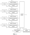
- FIG. 1 is a functional block diagram of a multi-battery electronic device according to a first embodiment of the present invention.
- the multi-battery electronic device includes a plurality of batteries 1, a plurality of battery detectors 2, and a control circuit 3.
- the plurality of battery detectors 2 are connected to the plurality of batteries 1, respectively, so as to detect battery status of the plurality of batteries 1, respectively.
- the control circuit 3 can be implemented by, for example, one or more of a micro-control unit, a system on a chip, a programmable logic array, and a field programmable logic array.
- the control circuit 3 is electrically connected to the plurality of battery detectors 2 for obtaining the battery status.
- the control circuit 3 is further electrically connected to various loads of the multi-battery electronic device, so as to control an operating frequency of each of the loads.
- power consumption settings of a central processing unit include a first power limit PL1, a second power limit PL2, a third power limit PL3, a fourth power limit PL4, and other power consumption levels.
- the first power limit PL1 usually represents thermal design power consumption
- the second power limit PL2 represents a short-term power consumption, which is suitable for a full load operation or an overclocking state at an accelerated boost frequency (that is, the highest power consumption that can be achieved when the CPU operates at a high clock). Therefore, the second power limit PL2 is usually greater than the first power limit PL1, and the third power limit PL3 and the fourth power limit PL4 are modes with higher power consumptions.
- Each of the plurality of battery detectors 2 includes a capacity detection circuit 21.
- Each of the capacity detection circuits 21 is used to detect a current capacity of the corresponding battery 1.
- the control circuit 3 obtains the current capacities of the plurality of batteries 1 by the plurality of capacity detection circuits 21, respectively.
- the control circuit 3 determines whether a current capacity difference between any two of the plurality of batteries 1 is greater than a capacity difference threshold.
- the control circuit 3 When the current capacity difference between any two of the plurality of batteries 1 is greater than the capacity difference threshold, the control circuit 3 enables the multi-battery electronic device to enter a load reduction mode, and the plurality of battery detectors 2 continue to detect the capacity status of each of the plurality of batteries 1.
- the multi-battery electronic device stays in a normal mode, and each of the plurality of battery detectors 2 continues to detect the capacity status of the corresponding battery 1.
- FIG. 2 is a flowchart of a protection method that is applicable to the multi-battery electronic device of FIG. 1 , and the protection method of FIG. 2 includes configuring the control circuit 3 to perform the following steps.
- step S201 the plurality of capacity detection circuits 21 detect the current capacities of the plurality of batteries 1, respectively.
- step S202 the control circuit 3 determines whether the current capacity difference between any two of the plurality of batteries 1 is greater than the capacity difference threshold.
- step S202 is followed by step S203.
- the protection method returns to step S201.
- step S203 the control circuit 3 controls the multi-battery electronic device to enter a first load reduction stage of the load reduction mode and then the protection method returns to step S201.
- the load reduction mode includes the first load reduction stage and a second load reduction stage.
- the control circuit 3 reduces an operating frequency of a video graphics adapter 4
- the multi-battery electronic device enters the first load reduction stage of the load reduction mode.
- the multi-battery electronic device enters the second load reduction stage of the load reduction mode.
- the first power limit PL1, the second power limit PL2, and the fourth power limit PL4 of the central processing unit 5 are 45 W, 109 W, and 109 W, respectively.
- the first power limit PL1, the second power limit PL2, and the fourth power limit PL4 of the CPU 5 are 10 W, 10 W, and 109 W, respectively.
- the first power limit PL1, the second power limit PL2, and the fourth power limit PL4 of the CPU 5 are 6.5 W, 6.5 W, and 109 W, respectively.
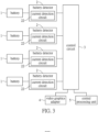
- FIG. 3 is a functional block diagram of a multi-battery electronic device according to a second embodiment of the present invention.
- each of the plurality of battery detectors 2 of FIG. 3 includes a current detection circuit 22.
- Each of current detection circuits 22 is used to detect a discharge current of the corresponding battery 1, and the control circuit 3 obtains the discharge currents of the plurality of batteries 1 by the plurality of current detection circuits 22, respectively.
- control circuit 3 determines that the discharge current of any one of the plurality of batteries 1 is greater than a current upper limit, the control circuit 3 controls the multi-battery electronic device to enter the load reduction mode, and each of the plurality of battery detectors 2 continues to detect the discharge current of the corresponding battery 1.
- the control circuit 3 determines that the discharge currents of the plurality of batteries 1 are not greater than the current upper limit, the multi-battery electronic device stays in the normal mode, and each of the plurality of battery detectors 2 continues to detect the discharge current of the corresponding battery 1.
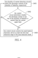
- FIG. 4 is a flowchart of a protection method that is applicable to the multi-battery electronic device of FIG. 3 , and the protection method of FIG. 4 includes configuring the control circuit 3 to perform the following steps.
- step S401 the plurality of current detection circuits 22 detect the discharge currents of the plurality of batteries 1, respectively.
- step S402 the control circuit 3 determines whether the discharge current of any one of the plurality of batteries 1 is greater than the current upper limit.
- step S402 is followed by step S403.
- the protection method returns to step S401.
- step S403 the control circuit 3 controls the multi-battery electronic device to enter the first load reduction stage of the load reduction mode and then the protection method returns to step S401.
- the current upper limit is set to be 6 amps (A).
- the control circuit 3 determines that the discharge current of any one of the plurality of batteries 1 is greater than 6 amps, the control circuit 3 reduces the operating frequency of the video graphics adapter 4, so that the multi-battery electronic enters the first load reduction stage of the load reduction mode.
- control circuit 3 determines that the temperature of any one of the plurality of batteries 1 is not within a temperature protection range, the control circuit 3 controls the multi-battery electronic device to enter the load reduction mode, and then each of the plurality of temperature detection circuits 23 continues to detect the temperature of the corresponding battery 1.
- the first power limit PL1, the second power limit PL2, and the fourth power limit PL4 of the central processing unit 5 are 10 W, 10 W, and 109 W, respectively.
- the first power limit PL1, the second power limit PL2, and the fourth power limit PL4 of the central processing unit 5 are 6.5 W, 6.5 W, and 109 W, respectively.
- step S809 the plurality of temperature detection circuits 23 detect the temperatures of the plurality of batteries 1, respectively.
- step S810 the control circuit 3 determines whether the temperature of any one of the plurality of batteries 1 is within the temperature protection range.
- the protection method returns to step S809.
- step S811 the control circuit 3 controls the multi-battery electronic device to enter the first load reduction stage of the load reduction mode, and then the protection method returns to step S809.
- the load will be reduced immediately, so as to prevent battery power from being exhausted by the load and enable the load to operate normally.
Landscapes
- Engineering & Computer Science (AREA)
- Theoretical Computer Science (AREA)
- Power Engineering (AREA)
- Physics & Mathematics (AREA)
- General Physics & Mathematics (AREA)
- General Engineering & Computer Science (AREA)
- Chemical Kinetics & Catalysis (AREA)
- General Chemical & Material Sciences (AREA)
- Electrochemistry (AREA)
- Chemical & Material Sciences (AREA)
- Manufacturing & Machinery (AREA)
- Microelectronics & Electronic Packaging (AREA)
- Human Computer Interaction (AREA)
- Protection Of Static Devices (AREA)
- Secondary Cells (AREA)
- Charge And Discharge Circuits For Batteries Or The Like (AREA)
Abstract
A multi-battery electronic device and a protection method thereof are provided. The multi-battery electronic device includes a plurality of batteries (1), a plurality of battery detectors (2), and a control circuit (3). The plurality of battery detectors (2) are connected to the plurality of batteries (1), respectively. The control circuit (3) is configured to detect battery status of the plurality of batteries (1) by the plurality of battery detectors (2), respectively. When the control circuit (3) determines that a current capacity difference between any two of the plurality of batteries (1) is greater than a capacity difference threshold, the control circuit (3) controls the multi-battery electronic device to enter a load reduction mode.
Description
- The present invention relates to an electronic device and a protection method thereof, and more particularly to an electronic device that supports multiple batteries and a protection method thereof.
- Conventionally, only a single charger and a single battery are disposed in an interior of a computer device. When the computer device is equipped with a high-performance video graphics adapter, a system power consumption of the computer device can sometimes be as high as 400 watts (W). Since an output power of the single battery is only about 70 watts, the power of the computer device is very likely to be instantaneously interrupted, which may even cause damage to the battery.
- In response to the above-referenced technical inadequacies, the present invention provides a multi-battery electronic device and a protection method thereof.
- In order to solve the above-mentioned problems, one of the technical aspects adopted by the present invention is to provide a multi-battery electronic device, which includes a plurality of batteries, a plurality of battery detectors, and a control circuit. The plurality of battery detectors are connected to the plurality of batteries, respectively. The control circuit is configured to detect battery status of the plurality of batteries by the plurality of battery detectors. When the control circuit determines that a current capacity difference between any two of the plurality of batteries is greater than a capacity difference threshold, the control circuit controls the multi-battery electronic device to enter a load reduction mode.
- In order to solve the above-mentioned problems, another one of the technical aspects adopted by the present invention is to provide a protection method of a multi-battery electronic device. The protection method includes configuring a control circuit to perform following: detecting battery status of a plurality of batteries by a plurality of battery detectors, respectively; determining whether a current capacity difference between any two of the plurality of batteries is greater than a capacity difference threshold; and controlling, when the current capacity difference between any two of the plurality of batteries is determined to be greater than the capacity difference threshold, the control circuit controls the multi-battery electronic device to enter a load reduction mode.
- Therefore, in the multi-battery electronic device and the protection method thereof provided by the present invention, as long as the capacity difference between any two of plurality of batteries is abnormal, the multi-battery electronic device will be controlled to immediately enter the load reduction mode, so as to prevent the power of the batteries from being exhausted by a load.
- These and other aspects of the present invention will become apparent from the following description of the embodiment taken in conjunction with the following drawings and their captions, although variations and modifications therein may be affected without departing from the spirit and scope of the novel concepts of the invention.
- The described embodiments may be better understood by reference to the following description and the accompanying drawings, in which:
-
FIG. 1 is a functional block diagram of a multi-battery electronic device according to a first embodiment of the present invention; -
FIG. 2 is a flowchart of a protection method that is applicable to the multi-battery electronic device ofFIG. 1 ; -
FIG. 3 is a functional block diagram of a multi-battery electronic device according to a second embodiment of the present invention; -
FIG. 4 is a flowchart of a protection method that is applicable to the multi-battery electronic device ofFIG. 3 ; -
FIG. 5 is a functional block diagram of a multi-battery electronic device according to a third embodiment of the present invention; -
FIG. 6 is a flowchart of a protection method that is applicable to the multi-battery electronic device ofFIG. 5 ; -
FIG. 7 is a functional block diagram of a multi-battery electronic device according to a fourth embodiment of the present invention; and -
FIG. 8 (FIG. 8A ,FIG. 8B andFIG. 8C ) is a flowchart of a protection method that is applicable to the multi-battery electronic device ofFIG. 7 . - The present invention is more particularly described in the following examples that are intended as illustrative only since numerous modifications and variations therein will be apparent to those skilled in the art. Like numbers in the drawings indicate like components throughout the views. As used in the description herein and throughout the claims that follow, unless the context clearly dictates otherwise, the meaning of "a," "an" and "the" includes plural reference, and the meaning of "in" includes "in" and "on." Titles or subtitles can be used herein for the convenience of a reader, which shall have no influence on the scope of the present invention.
- The terms used herein generally have their ordinary meanings in the art. In the case of conflict, the present document, including any definitions given herein, will prevail. The same thing can be expressed in more than one way. Alternative language and synonyms can be used for any term(s) discussed herein, and no special significance is to be placed upon whether a term is elaborated or discussed herein. A recital of one or more synonyms does not exclude the use of other synonyms. The use of examples anywhere in this specification including examples of any terms is illustrative only, and in no way limits the scope and meaning of the present invention or of any exemplified term. Likewise, the present invention is not limited to various embodiments given herein. Numbering terms such as "first," "second" or "third" can be used to describe various components, signals or the like, which are for distinguishing one component/signal from another one only, and are not intended to, nor should be construed to impose any substantive limitations on the components, signals or the like.
-
FIG. 1 is a functional block diagram of a multi-battery electronic device according to a first embodiment of the present invention. Referring toFIG. 1 , the multi-battery electronic device includes a plurality ofbatteries 1, a plurality ofbattery detectors 2, and acontrol circuit 3. The plurality ofbattery detectors 2 are connected to the plurality ofbatteries 1, respectively, so as to detect battery status of the plurality ofbatteries 1, respectively. Thecontrol circuit 3 can be implemented by, for example, one or more of a micro-control unit, a system on a chip, a programmable logic array, and a field programmable logic array. Thecontrol circuit 3 is electrically connected to the plurality ofbattery detectors 2 for obtaining the battery status. Thecontrol circuit 3 is further electrically connected to various loads of the multi-battery electronic device, so as to control an operating frequency of each of the loads. - When a task processed by the multi-battery electronic device becomes more complex and requires more system resources, a power consumption of the load increases accordingly. For example, power consumption settings of a central processing unit (CPU) include a first power limit PL1, a second power limit PL2, a third power limit PL3, a fourth power limit PL4, and other power consumption levels. The first power limit PL1 usually represents thermal design power consumption, and the second power limit PL2 represents a short-term power consumption, which is suitable for a full load operation or an overclocking state at an accelerated boost frequency (that is, the highest power consumption that can be achieved when the CPU operates at a high clock). Therefore, the second power limit PL2 is usually greater than the first power limit PL1, and the third power limit PL3 and the fourth power limit PL4 are modes with higher power consumptions.
- Each of the plurality of
battery detectors 2 includes acapacity detection circuit 21. Each of thecapacity detection circuits 21 is used to detect a current capacity of thecorresponding battery 1. Thecontrol circuit 3 obtains the current capacities of the plurality ofbatteries 1 by the plurality ofcapacity detection circuits 21, respectively. Thecontrol circuit 3 determines whether a current capacity difference between any two of the plurality ofbatteries 1 is greater than a capacity difference threshold. - When the current capacity difference between any two of the plurality of
batteries 1 is greater than the capacity difference threshold, thecontrol circuit 3 enables the multi-battery electronic device to enter a load reduction mode, and the plurality ofbattery detectors 2 continue to detect the capacity status of each of the plurality ofbatteries 1. - When the current capacity differences between the plurality of
batteries 1 are not greater than the capacity difference threshold, the multi-battery electronic device stays in a normal mode, and each of the plurality ofbattery detectors 2 continues to detect the capacity status of thecorresponding battery 1. -
FIG. 2 is a flowchart of a protection method that is applicable to the multi-battery electronic device ofFIG. 1 , and the protection method ofFIG. 2 includes configuring thecontrol circuit 3 to perform the following steps. In step S201, the plurality ofcapacity detection circuits 21 detect the current capacities of the plurality ofbatteries 1, respectively. - In step S202, the
control circuit 3 determines whether the current capacity difference between any two of the plurality ofbatteries 1 is greater than the capacity difference threshold. - When the current capacity difference between any two of the plurality of
batteries 1 is greater than the capacity difference threshold, step S202 is followed by step S203. - When the current capacity differences between the plurality of
batteries 1 are not greater than the capacity difference threshold, the protection method returns to step S201. - In step S203, the
control circuit 3 controls the multi-battery electronic device to enter a first load reduction stage of the load reduction mode and then the protection method returns to step S201. - Specifically, the load reduction mode includes the first load reduction stage and a second load reduction stage. When the
control circuit 3 reduces an operating frequency of avideo graphics adapter 4, the multi-battery electronic device enters the first load reduction stage of the load reduction mode. - When the
control circuit 3 reduces the operating frequency of thevideo graphics adapter 4 and an operating frequency of acentral processing unit 5 at the same time, the multi-battery electronic device enters the second load reduction stage of the load reduction mode. - For example, in the normal mode, the first power limit PL1, the second power limit PL2, and the fourth power limit PL4 of the
central processing unit 5 are 45 W, 109 W, and 109 W, respectively. - In the first load reduction stage of the load reduction mode, the first power limit PL1, the second power limit PL2, and the fourth power limit PL4 of the
CPU 5 are 10 W, 10 W, and 109 W, respectively. - In the second load reduction stage of the load reduction mode, the first power limit PL1, the second power limit PL2, and the fourth power limit PL4 of the
CPU 5 are 6.5 W, 6.5 W, and 109 W, respectively. - Through the protection method of
FIG. 2 , as long as the capacity difference between any two of thebatteries 1 is abnormal, the load will be reduced immediately, so as to prevent the power of thebatteries 1 from being exhausted by the load. -
FIG. 3 is a functional block diagram of a multi-battery electronic device according to a second embodiment of the present invention. Compared withFIG. 1 , each of the plurality ofbattery detectors 2 ofFIG. 3 includes acurrent detection circuit 22. Each ofcurrent detection circuits 22 is used to detect a discharge current of thecorresponding battery 1, and thecontrol circuit 3 obtains the discharge currents of the plurality ofbatteries 1 by the plurality ofcurrent detection circuits 22, respectively. - When the
control circuit 3 determines that the discharge current of any one of the plurality ofbatteries 1 is greater than a current upper limit, thecontrol circuit 3 controls the multi-battery electronic device to enter the load reduction mode, and each of the plurality ofbattery detectors 2 continues to detect the discharge current of thecorresponding battery 1. - When the
control circuit 3 determines that the discharge currents of the plurality ofbatteries 1 are not greater than the current upper limit, the multi-battery electronic device stays in the normal mode, and each of the plurality ofbattery detectors 2 continues to detect the discharge current of thecorresponding battery 1. -
FIG. 4 is a flowchart of a protection method that is applicable to the multi-battery electronic device ofFIG. 3 , and the protection method ofFIG. 4 includes configuring thecontrol circuit 3 to perform the following steps. - In step S401, the plurality of
current detection circuits 22 detect the discharge currents of the plurality ofbatteries 1, respectively. - In step S402, the
control circuit 3 determines whether the discharge current of any one of the plurality ofbatteries 1 is greater than the current upper limit. - When the discharge current of any one of the plurality of
batteries 1 is greater than the current upper limit, step S402 is followed by step S403. - When the discharge currents of the plurality of
batteries 1 are not greater than the current upper limit, the protection method returns to step S401. - In step S403, the
control circuit 3 controls the multi-battery electronic device to enter the first load reduction stage of the load reduction mode and then the protection method returns to step S401. - For example, the current upper limit is set to be 6 amps (A). When the
control circuit 3 determines that the discharge current of any one of the plurality ofbatteries 1 is greater than 6 amps, thecontrol circuit 3 reduces the operating frequency of thevideo graphics adapter 4, so that the multi-battery electronic enters the first load reduction stage of the load reduction mode. - Through the protection method of
FIG. 4 , as long as the discharge current of any one ofbatteries 1 is abnormal, the load will be reduced immediately, so as to prevent the power of thebatteries 1 from being exhausted by the load. -
FIG. 5 is a functional block diagram of a multi-battery electronic device according to a third embodiment of the present invention. Compared withFIG. 1 , each of the plurality ofbattery detectors 2 ofFIG. 5 includes atemperature detection circuit 23. Each of thetemperature detection circuits 23 is used to detect a temperature of thecorresponding battery 1, and thecontrol circuit 3 obtains the temperatures of the plurality ofbatteries 1 by the plurality oftemperature detection circuits 23, respectively. - When the
control circuit 3 determines that the temperature of any one of the plurality ofbatteries 1 is not within a temperature protection range, thecontrol circuit 3 controls the multi-battery electronic device to enter the load reduction mode, and then each of the plurality oftemperature detection circuits 23 continues to detect the temperature of thecorresponding battery 1. - When the
control circuit 3 determines that the temperatures of the plurality ofbatteries 1 are within the temperature protection range, the multi-battery electronic device maintains the normal mode and then each of the plurality oftemperature detection circuits 23 continues to detect the temperature of thecorresponding battery 1. -
FIG. 6 is a flowchart of a protection method that is applicable to the multi-battery electronic device ofFIG. 5 , and the protection method ofFIG. 6 includes configuring thecontrol circuit 3 to perform the following steps. - In step S601, the plurality of
temperature detection circuits 23 detect the temperatures of the plurality ofbatteries 1, respectively. - In step S602, the
control circuit 3 determines whether the temperature of any one of the plurality ofbatteries 1 is within the temperature protection range. - When the temperatures of the plurality of
batteries 1 are within the temperature protection range, the protection method returns to step S601. - When the temperature of any one of the plurality of
batteries 1 is not within the temperature protection range, step S602 is followed by step S603. - In step S603, the
control circuit 3 controls the multi-battery electronic device to enter the first load reduction stage of the load reduction mode, and then the protection method returns to step S601. - For example, the temperature protection range is from -17°C to 50°C. When the
control circuit 3 determines that the temperature of any one of the plurality ofbatteries 1 is lower than -17°C or greater than 50°C, thecontrol circuit 3 reduces the operating frequency of thevideo graphics adapter 4, so that the multi-battery electronic device enters the first load reduction stage of the load reduction mode. - Through the protection method of
FIG. 6 , even when the multi-battery electronic device is placed in an extreme climate environment, thebatteries 1 can still provide power to the load in a normal manner, so that the load can operate normally. -
FIG. 7 is a functional block diagram of a multi-battery electronic device according to a fourth embodiment of the present invention. Compared withFIG. 1 , each of the plurality ofbattery detectors 2 ofFIG. 7 includes thecapacity detection circuit 21, thecurrent detection circuit 22, and thetemperature detection circuit 23. Thecapacity detection circuit 21 is used to detect the current capacity of thecorresponding battery 1. Thecurrent detection circuit 22 is used to detect the discharge current of thecorresponding battery 1. Thetemperature detection circuit 23 is used to detect the temperature of thecorresponding battery 1. Thecontrol circuit 3 obtains the current capacities, the discharge currents, and the temperatures, respectively from the plurality ofcapacity detection circuits 21, the plurality ofcurrent detection circuits 22, and the plurality oftemperature detection circuits 23. -
FIG. 8 (FIG. 8A ,FIG. 8B andFIG. 8C ) is a flowchart of a protection method that is applicable to the multi-battery electronic device ofFIG. 7 , and the protection method ofFIG. 8 includes configuring thecontrol circuit 3 to perform the following steps. - In step S801, the plurality of
capacity detection circuits 21 detect the current capacities of the plurality ofbatteries 1, respectively. - In step S802, the
control circuit 3 determines whether the current capacity difference between any two of the plurality ofbatteries 1 is greater than the capacity difference threshold. - When the current capacity difference between any two of the plurality of
batteries 1 is greater than the capacity difference threshold, step S802 is followed by step S803. - When the current capacity differences between the plurality of
batteries 1 are not greater than the capacity difference threshold, the protection method returns to step S801. - In step S803, the
control circuit 3 controls the multi-battery electronic device to enter the first load reduction stage of the load reduction mode, and then the protection method returns to step S801. - In step S804, the plurality of
current detection circuits 22 detect the discharge currents of the plurality ofbatteries 1, respectively. - For example, the
control circuit 3 can determine a relationship between the discharge current, a first current upper limit, and a second current upper limit. In this embodiment, the second upper current limit is configured to be greater than the first upper current limit. - In step S805, the
control circuit 3 determines whether the discharge current of any one of the plurality ofbatteries 1 is greater than the first upper current limit. - When the discharge current of any one of the plurality of
batteries 1 is greater than the first upper current limit, step S805 is followed by step S806. - When the discharge currents of the plurality of
batteries 1 are not greater than the first upper current limit, the protection method returns to step S804. - In step S806, the
control circuit 3 determines whether the discharge current of any one of the plurality ofbatteries 1 is greater than the second upper current limit, and the second upper current limit is greater than the first current upper limit. - When the discharge current of any one of the plurality of
batteries 1 is greater than the second upper current limit, step S806 is followed by step S807. - When the discharge currents of the plurality of
batteries 1 are not greater than the second upper current limit, step S806 is followed by step S808. - In step S807, the
control circuit 3 controls the multi-battery electronic device to enter the second load reduction stage of the load reduction mode, and then the protection method returns to step S804. - In step S808, the
control circuit 3 controls the multi-battery electronic device to enter the first load reduction stage of the load reduction mode, and then the protection method returns to step S804. - For example, the first current upper limit is 4 amps, and the second current upper limit is 7 amps. When the discharge currents of the
batteries 1 are lower than 4 amps, the multi-battery electronic device remains in the normal mode. In the normal mode, the first power limit PL1, the second power limit PL2, and the fourth power limit PL4 of thecentral processing unit 5 are 45 W, 109 W, and 109 W, respectively. - When the discharge current of any one of the plurality of
batteries 1 is greater than 4 amps and less than 7 amps, thecontrol circuit 3 reduces the operating frequency of thevideo graphics adapter 4, so that the multi-battery electronic device enters the first load reduction stage of the load reduction mode. - In the first load reduction stage, the first power limit PL1, the second power limit PL2, and the fourth power limit PL4 of the
central processing unit 5 are 10 W, 10 W, and 109 W, respectively. - When the
control circuit 3 determines that the discharge current of any one of the plurality ofbatteries 1 is greater than 7 amps, thecontrol circuit 3 simultaneously reduces the operating frequencies of thevideo graphics adapter 4 and thecentral processing unit 5, so that the multi-battery electronic device enters the second load reduction stage of the load reduction mode. - In the second load reduction stage, the first power limit PL1, the second power limit PL2, and the fourth power limit PL4 of the
central processing unit 5 are 6.5 W, 6.5 W, and 109 W, respectively. - In step S809, the plurality of
temperature detection circuits 23 detect the temperatures of the plurality ofbatteries 1, respectively. - In step S810, the
control circuit 3 determines whether the temperature of any one of the plurality ofbatteries 1 is within the temperature protection range. - When the temperatures of the plurality of
batteries 1 are within the temperature protection range, the protection method returns to step S809. - When the temperature of any one of the plurality of
batteries 1 is not within the temperature protection range, step S810 is followed by step S811. - In step S811, the
control circuit 3 controls the multi-battery electronic device to enter the first load reduction stage of the load reduction mode, and then the protection method returns to step S809. - Furthermore, steps S801, S804 and S809 of
FIG. 8 can be performed simultaneously or sequentially. - Through the protection method of
FIG. 8 , as long as any one of the battery capacity difference, the discharge current, and the temperature is abnormal, the load will be reduced immediately, so as to prevent the power of thebatteries 1 from being exhausted by the load and enable the load to operate normally. - In conclusion, in the multi-battery electronic device and the protection method thereof provided by the present invention, as long as any one of the battery capacity difference, the discharge current, and the temperature is abnormal, the load will be reduced immediately, so as to prevent battery power from being exhausted by the load and enable the load to operate normally.
Claims (10)
- A multi-battery electronic device, characterized by comprising:a plurality of batteries (1);a plurality of battery detectors (2) connected to the plurality of batteries(1), respectively; anda control circuit (3), wherein the control circuit (3) is configured to detect battery status of the plurality of batteries (1) by the plurality of battery detectors (2);wherein, when the control circuit (3) determines that a current capacity difference between any two of the plurality of batteries (1) is greater than a capacity difference threshold, the control circuit (3) controls the multi-battery electronic device to enter a load reduction mode.
- The multi-battery electronic device according to claim 1, wherein the control circuit (3) is further configured to control the multi-battery electronic device to enter the load reduction mode when a discharge current of any one of the plurality of batteries (1) is greater than a first upper current limit.
- The multi-battery electronic device according to claim 1, wherein the control circuit (3) is further configured to control the multi-battery electronic device to enter the load reduction mode when a temperature of any one of the plurality of batteries (1) exceeds a temperature protection range.
- The multi-battery electronic device according to claim 1, further comprising a central processing unit (5) and a video graphics adapter (4); wherein, when the multi-battery electronic device enters the load reduction mode, an operating frequency of at least one of the central processing unit (5)or the video graphics adapter (4) is reduced.
- The multi-battery electronic device according to claim 2, further comprising a central processing unit (5) and a video graphics adapter (4); wherein the load reduction mode comprises a first load reduction stage and a second load reduction stage, an operating frequency of the video graphics adapter (4) is reduced in the first load reduction stage, and the operating frequency of the video graphics adapter (4) and an operating frequency of the central processing unit (5) are reduced in the second load reduction stage.
- The multi-battery electronic device according to claim 5, wherein the control circuit (3) is further configured to control the multi-battery electronic device to enter the first load reduction stage when the discharge current of any one of the plurality of batteries (1) is greater than the first upper current limit; wherein the control circuit (3) is further configured to control the multi-battery electronic device to enter the second load reduction stage when the discharge current of any one of the plurality of batteries (1) is greater than a second upper current limit; wherein the first upper current limit is less than the second upper current limit.
- A protection method of a multi-battery electronic device, characterized by comprising: configuring a control circuit (3) to perform following:detecting battery status of a plurality of batteries (1) by a plurality of battery detectors (2), respectively;determining whether a current capacity difference between any two of the plurality of batteries (1) is greater than a capacity difference threshold; andcontrolling, when the current capacity difference between any two of the plurality of batteries (1) is determined to be greater than the capacity difference threshold, the multi-battery electronic device to enter a load reduction mode.
- The protection method according to claim 7, further comprising: determining whether a discharge current of any one of the plurality of batteries (1) is greater than a first current upper limit; wherein when the discharge current of any one of the plurality of batteries (1) is greater than the first current upper limit, the control circuit (3) controls the multi-battery electronic device to enter the load reduction mode.
- The protection method according to claim 7, further comprising: determining whether a temperature of any one of the plurality of batteries (1) exceeds a temperature protection range; wherein when the temperature of any one of the plurality of batteries (1) exceeds the temperature protection range, the control circuit (3) controls the multi-battery electronic device to enter the load reduction mode.
- The protection method according to claim 7, further comprising:determining whether a discharge current of any one of the plurality of batteries (1) is greater than a first current upper limit; anddetermining whether the discharge current is greater than a second current upper limit when the discharge current is greater than the first current upper limit;wherein the second current upper limit is greater than the first current upper limit, and the multi-battery electronic device remains in a normal mode when the discharge currents of the plurality of batteries (1) are not greater than the first current upper limit;wherein when the discharge current of any one of the plurality of batteries (1) is greater than the first current upper limit but not greater than the second current upper limit, the control circuit (3) controls the multi-battery electronic device to enter a first load reduction stage of the load reduction mode;wherein when the discharge current of any one of the plurality of batteries (1) is greater than the second current upper limit, the control circuit (3) controls the multi-battery electronic device to enter a second load reduction stage of the load reduction mode.
Applications Claiming Priority (1)
| Application Number | Priority Date | Filing Date | Title |
|---|---|---|---|
| CN202310959897.XA CN119448464A (en) | 2023-08-01 | 2023-08-01 | Multi-battery electronic device and protection method thereof |
Publications (1)
| Publication Number | Publication Date |
|---|---|
| EP4502762A1 true EP4502762A1 (en) | 2025-02-05 |
Family
ID=91759614
Family Applications (1)
| Application Number | Title | Priority Date | Filing Date |
|---|---|---|---|
| EP24185649.1A Pending EP4502762A1 (en) | 2023-08-01 | 2024-07-01 | Multi-battery electronic device and protection method thereof |
Country Status (3)
| Country | Link |
|---|---|
| US (1) | US20250044855A1 (en) |
| EP (1) | EP4502762A1 (en) |
| CN (1) | CN119448464A (en) |
Citations (3)
| Publication number | Priority date | Publication date | Assignee | Title |
|---|---|---|---|---|
| US20040070371A1 (en) * | 2002-10-11 | 2004-04-15 | Compaq Information Technologies Group, L.P. | Power management of a battery operated computer system based on battery status |
| CN111240458A (en) * | 2020-01-02 | 2020-06-05 | 上海闻泰信息技术有限公司 | CPU frequency reduction method, system and portable computer |
| US20210135478A1 (en) * | 2020-12-23 | 2021-05-06 | Intel Corporation | Workload dependent load-sharing mechanism in multi-battery system, and adaptive charging and discharging for a hybrid battery |
-
2023
- 2023-08-01 CN CN202310959897.XA patent/CN119448464A/en active Pending
-
2024
- 2024-06-11 US US18/739,453 patent/US20250044855A1/en active Pending
- 2024-07-01 EP EP24185649.1A patent/EP4502762A1/en active Pending
Patent Citations (3)
| Publication number | Priority date | Publication date | Assignee | Title |
|---|---|---|---|---|
| US20040070371A1 (en) * | 2002-10-11 | 2004-04-15 | Compaq Information Technologies Group, L.P. | Power management of a battery operated computer system based on battery status |
| CN111240458A (en) * | 2020-01-02 | 2020-06-05 | 上海闻泰信息技术有限公司 | CPU frequency reduction method, system and portable computer |
| US20210135478A1 (en) * | 2020-12-23 | 2021-05-06 | Intel Corporation | Workload dependent load-sharing mechanism in multi-battery system, and adaptive charging and discharging for a hybrid battery |
Also Published As
| Publication number | Publication date |
|---|---|
| US20250044855A1 (en) | 2025-02-06 |
| CN119448464A (en) | 2025-02-14 |
Similar Documents
| Publication | Publication Date | Title |
|---|---|---|
| US8405357B2 (en) | Battery unit, battery system, electronic device, charging control method of battery, and discharging control method of battery | |
| US8812885B2 (en) | Detecting wake-up events for a chip based on an I/O power supply | |
| US11411391B2 (en) | Energy storage system protection system | |
| EP2893608B1 (en) | Method and system for voltage collapse protection | |
| US20150108833A1 (en) | Distribution board and electric power control method | |
| US5909583A (en) | Method for making redundant power supplies hot-pluggable | |
| US20140032952A1 (en) | Electronic apparatus and drive control method thereof | |
| WO2018070306A1 (en) | Power supply control circuit, electronic device, and power supply control method | |
| US20130205140A1 (en) | Electronic apparatus and driving control method thereof | |
| US11646600B2 (en) | Energy storage system convertible to uninterruptible power supply | |
| US7330984B2 (en) | Power monitoring circuit having automatic feedback and overload protection | |
| US8707097B2 (en) | Information processing apparatus, control apparatus, and method | |
| US20250044855A1 (en) | Multi-battery electronic device and protection method thereof | |
| AU2022435875A1 (en) | Method and apparatus for unit control and photovoltaic multi-unit air conditioning system | |
| JP2008131670A (en) | Battery voltage monitoring device | |
| TWI900875B (en) | Multi-battery electronic device and protection method thereof | |
| AU2024330648A1 (en) | System for reducing battery cell failure propagation risk of a rechargeable battery | |
| CN105762870A (en) | Battery having protection and early warning functions and electronic equipment having the battery | |
| EP4510420A2 (en) | Power management system and power management method | |
| AU2023263494A1 (en) | Electronic device with hybrid power source and method for hybrid power supply | |
| CN110235298A (en) | battery pack with communication terminal isolation function | |
| US6560083B2 (en) | Dynamic critical battery detection mechanism | |
| US10298055B1 (en) | Power supply with programmable restriction | |
| CN105811505A (en) | Battery having protection pre-warning function and electronic device with same | |
| US20130175861A1 (en) | Control option combining a power-down signal with an analog input signal |
Legal Events
| Date | Code | Title | Description |
|---|---|---|---|
| PUAI | Public reference made under article 153(3) epc to a published international application that has entered the european phase |
Free format text: ORIGINAL CODE: 0009012 |
|
| STAA | Information on the status of an ep patent application or granted ep patent |
Free format text: STATUS: THE APPLICATION HAS BEEN PUBLISHED |
|
| AK | Designated contracting states |
Kind code of ref document: A1 Designated state(s): AL AT BE BG CH CY CZ DE DK EE ES FI FR GB GR HR HU IE IS IT LI LT LU LV MC ME MK MT NL NO PL PT RO RS SE SI SK SM TR |
|
| STAA | Information on the status of an ep patent application or granted ep patent |
Free format text: STATUS: REQUEST FOR EXAMINATION WAS MADE |
|
| 17P | Request for examination filed |
Effective date: 20250425 |