EP4502703A1 - Virtual image display device - Google Patents
Virtual image display device Download PDFInfo
- Publication number
- EP4502703A1 EP4502703A1 EP23780483.6A EP23780483A EP4502703A1 EP 4502703 A1 EP4502703 A1 EP 4502703A1 EP 23780483 A EP23780483 A EP 23780483A EP 4502703 A1 EP4502703 A1 EP 4502703A1
- Authority
- EP
- European Patent Office
- Prior art keywords
- light
- guide plate
- image display
- light guide
- display apparatus
- Prior art date
- Legal status (The legal status is an assumption and is not a legal conclusion. Google has not performed a legal analysis and makes no representation as to the accuracy of the status listed.)
- Pending
Links
Images




Classifications
-
- G—PHYSICS
- G02—OPTICS
- G02B—OPTICAL ELEMENTS, SYSTEMS OR APPARATUS
- G02B6/00—Light guides; Structural details of arrangements comprising light guides and other optical elements, e.g. couplings
- G02B6/0001—Light guides; Structural details of arrangements comprising light guides and other optical elements, e.g. couplings specially adapted for lighting devices or systems
- G02B6/0011—Light guides; Structural details of arrangements comprising light guides and other optical elements, e.g. couplings specially adapted for lighting devices or systems the light guides being planar or of plate-like form
- G02B6/0033—Means for improving the coupling-out of light from the light guide
- G02B6/0056—Means for improving the coupling-out of light from the light guide for producing polarisation effects, e.g. by a surface with polarizing properties or by an additional polarizing elements
-
- G—PHYSICS
- G02—OPTICS
- G02B—OPTICAL ELEMENTS, SYSTEMS OR APPARATUS
- G02B27/00—Optical systems or apparatus not provided for by any of the groups G02B1/00 - G02B26/00, G02B30/00
- G02B27/01—Head-up displays
-
- G—PHYSICS
- G02—OPTICS
- G02B—OPTICAL ELEMENTS, SYSTEMS OR APPARATUS
- G02B27/00—Optical systems or apparatus not provided for by any of the groups G02B1/00 - G02B26/00, G02B30/00
- G02B27/01—Head-up displays
- G02B27/0101—Head-up displays characterised by optical features
-
- G—PHYSICS
- G02—OPTICS
- G02B—OPTICAL ELEMENTS, SYSTEMS OR APPARATUS
- G02B27/00—Optical systems or apparatus not provided for by any of the groups G02B1/00 - G02B26/00, G02B30/00
- G02B27/01—Head-up displays
- G02B27/017—Head mounted
- G02B27/0172—Head mounted characterised by optical features
-
- G—PHYSICS
- G02—OPTICS
- G02B—OPTICAL ELEMENTS, SYSTEMS OR APPARATUS
- G02B6/00—Light guides; Structural details of arrangements comprising light guides and other optical elements, e.g. couplings
- G02B6/0001—Light guides; Structural details of arrangements comprising light guides and other optical elements, e.g. couplings specially adapted for lighting devices or systems
- G02B6/0011—Light guides; Structural details of arrangements comprising light guides and other optical elements, e.g. couplings specially adapted for lighting devices or systems the light guides being planar or of plate-like form
- G02B6/0033—Means for improving the coupling-out of light from the light guide
- G02B6/0035—Means for improving the coupling-out of light from the light guide provided on the surface of the light guide or in the bulk of it
- G02B6/004—Scattering dots or dot-like elements, e.g. microbeads, scattering particles, nanoparticles
- G02B6/0043—Scattering dots or dot-like elements, e.g. microbeads, scattering particles, nanoparticles provided on the surface of the light guide
-
- G—PHYSICS
- G02—OPTICS
- G02B—OPTICAL ELEMENTS, SYSTEMS OR APPARATUS
- G02B6/00—Light guides; Structural details of arrangements comprising light guides and other optical elements, e.g. couplings
- G02B6/0001—Light guides; Structural details of arrangements comprising light guides and other optical elements, e.g. couplings specially adapted for lighting devices or systems
- G02B6/0011—Light guides; Structural details of arrangements comprising light guides and other optical elements, e.g. couplings specially adapted for lighting devices or systems the light guides being planar or of plate-like form
- G02B6/0033—Means for improving the coupling-out of light from the light guide
- G02B6/005—Means for improving the coupling-out of light from the light guide provided by one optical element, or plurality thereof, placed on the light output side of the light guide
-
- G—PHYSICS
- G02—OPTICS
- G02B—OPTICAL ELEMENTS, SYSTEMS OR APPARATUS
- G02B27/00—Optical systems or apparatus not provided for by any of the groups G02B1/00 - G02B26/00, G02B30/00
- G02B27/01—Head-up displays
- G02B27/0101—Head-up displays characterised by optical features
- G02B2027/0118—Head-up displays characterised by optical features comprising devices for improving the contrast of the display / brillance control visibility
-
- G—PHYSICS
- G02—OPTICS
- G02B—OPTICAL ELEMENTS, SYSTEMS OR APPARATUS
- G02B27/00—Optical systems or apparatus not provided for by any of the groups G02B1/00 - G02B26/00, G02B30/00
- G02B27/01—Head-up displays
- G02B27/0101—Head-up displays characterised by optical features
- G02B2027/0118—Head-up displays characterised by optical features comprising devices for improving the contrast of the display / brillance control visibility
- G02B2027/012—Head-up displays characterised by optical features comprising devices for improving the contrast of the display / brillance control visibility comprising devices for attenuating parasitic image effects
-
- G—PHYSICS
- G02—OPTICS
- G02B—OPTICAL ELEMENTS, SYSTEMS OR APPARATUS
- G02B6/00—Light guides; Structural details of arrangements comprising light guides and other optical elements, e.g. couplings
- G02B6/0001—Light guides; Structural details of arrangements comprising light guides and other optical elements, e.g. couplings specially adapted for lighting devices or systems
- G02B6/0011—Light guides; Structural details of arrangements comprising light guides and other optical elements, e.g. couplings specially adapted for lighting devices or systems the light guides being planar or of plate-like form
- G02B6/0013—Means for improving the coupling-in of light from the light source into the light guide
- G02B6/0015—Means for improving the coupling-in of light from the light source into the light guide provided on the surface of the light guide or in the bulk of it
Definitions
- the present invention relates to a virtual image display apparatus. Specifically, the present invention relates to a virtual image display apparatus used for a head-up display.
- head-up display head-up display system
- windshield windshield glass
- windshield glass windshield glass
- the head-up display will also be referred to as "HUD”.
- HUD is an abbreviation for the "head up display”.
- the driver can obtain various information such as a map, a traveling speed, and a vehicle condition by the HUD while watching the external environment ahead of the driver without largely moving a visual line. Therefore, safer driving can be expected while obtaining various information.
- Fig. 12 conceptually shows an example of a general HUD.
- a HUD 100 is configured to include an image display unit 112, a reflecting mirror 116, a concave mirror 118, and a windshield 126 that acts as a reflective member for reflecting and projecting image light.
- the image display unit 112 is configured to include an image display device 130 such as a liquid crystal display, and a projection lens 131.
- the image display unit 112 the reflecting mirror 116, and the concave mirror 118 configure a projector of the HUD, and are accommodated in a lower portion of a dashboard 120 of a vehicle such as an automobile.
- the image displayed by the image display device 130 that is, the image light is projected by the projection lens 131, is reflected along a predetermined optical path by the reflecting mirror 116 and the concave mirror 118, transmits through a transmission window 124 provided in the dashboard 120, is incident into the windshield 126, and is reflected and projected to be observed as a projection image by a user O.
- the user O observes a virtual image of the image projected to the windshield 126.
- the projector used for the HUD 100 is accommodated in the lower portion of the dashboard of the vehicle as described above, and thus is largely limited in size. Therefore, in the projector for the HUD in the related art, a required optical path length is secured by folding the optical path using a plurality of mirrors.
- the projector used for the HUD 100 is likely to have a complicated structure. Further, as described above, a space in the lower portion of the dashboard is small, and thus the degree of freedom in the design of the projector is low.
- Fig. 13 conceptually shows an example of the HUD.
- a HUD 130 includes a light guide plate 132, an incidence diffraction element 134, and an emission diffraction element 136.
- image light G emitted from an image display device is diffracted by the incidence diffraction element 134 and is incident into the light guide plate 132 at an angle where total reflection occurs.
- the image light G incident into the light guide plate 132 is totally reflected repeatedly and is guided (propagates) in the light guide plate 132.
- the emission diffraction element 136 is provided on an upper surface (hereinafter, also referred to as an emission surface) of the light guide plate 132 in the drawing. A part of the light guided in the light guide plate 132 is incident into the emission diffraction element 136, is diffracted, and is emitted upward from the emission surface. The image light G emitted from the light guide plate 132 is incident into the windshield 126, is reflected and projected, and is observed as a projection image by the user O, as in the above-described case.
- the light guide plate 132 can be disposed above a dashboard of an automobile or the like. Therefore, the limit in size is significantly reduced as compared with the HUD 100 in the related art shown in Fig. 12 .
- the device configuration of the HUD can be simplified.
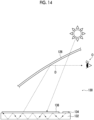
- external light such as sunlight transmits through the windshield 126 and enters into the vehicle to reach the light guide plate 132.
- the emission diffraction element 136 is provided on the emission surface of the light guide plate 132. Therefore, the external light is diffracted by the emission diffraction element 136 and is incident into the light guide plate 132 at an angle where total reflection occurs depending on an incidence direction.
- the external light incident into the light guide plate 132 as described above is totally reflected repeatedly and is guided in the light guide plate 132 as in the image light such that a part thereof is diffracted by the emission diffraction element 136 and is emitted from the light guide plate 132 together with the image light.
- the image light and the external light emitted from the light guide plate 132 are incident into the windshield 126 as in the above-described case, are reflected and projected, and are observed as interference light D by the user O. As a result, glare occurs in the image observed by the user O, and the user O feels dizzy due to the interference light D.
- the external light that is incident into the light guide plate 132 and is guided and emitted may be emitted from the light guide plate 132 to directly reach the user O as the interference light D without being incident into the windshield 126.
- JP2021-528681A external light such as sunlight is prevented from being incident into the light guide plate 132, glare of the image observed as the interference light D by the user O is suppressed, and the dizziness of the user O caused by the interference light D is suppressed.
- An object of the present invention is to provide a virtual image display apparatus for a HUD including a light guide plate and a diffraction element as in JP2021-528681A , in which observation of interference light by a user can be suppressed using a new method.
- the present invention has the following configurations.
- a virtual image display apparatus for a HUD including a light guide plate and a diffraction element
- observation of interference light by a user can be suppressed using a new method.
- visible light refers to light having a wavelength which can be observed by human eyes among electromagnetic waves and refers to light in a wavelength range of 380 to 780 nm.
- Invisible light refers to light in a wavelength range of shorter than 380 nm or longer than 780 nm.
- light in a wavelength range of 420 to 490 nm refers to blue light (B light)
- light in a wavelength range of 495 to 570 nm refers to green light (G light)
- light in a wavelength range of 620 to 750 nm refers to red light (R light).
- infrared light refers to invisible light in a wavelength range of longer than 780 nm and 2000 nm or shorter.
- parallel, perpendicular, orthogonal, or the like includes an error range generally allowed in the technical field.
- parallel, perpendicular, orthogonal, and the like represent that a difference from the exact match is within a range of less than 5°.
- the difference from the exact match is preferably less than 4° and more preferably less than 3°.
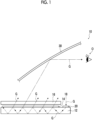
- Fig. 1 conceptually shows an example of a virtual image display apparatus according to a first aspect of the present invention.
- a virtual image display apparatus 10 shown in Fig. 1 is a virtual image display apparatus for a HUD, and includes a light guide plate 12, an emission diffraction element 14, a first polarizer 16, and an image display device 18.
- the virtual image display apparatus 10 displays (projects) an image to a user O, for example, using a windshield 30 of a vehicle such as an automobile.
- the emission diffraction element 14 is the emission element according to the embodiment of the present invention.
- the virtual image display apparatus 10 further includes an incidence diffraction element 20 and an intermediate diffraction element 24 (refer to Fig. 2 ).
- the virtual image display apparatus 10 is basically the same as the virtual image display apparatus (device that forms a virtual image (VB)) described in JP2021-528681A , except that it includes the first polarizer 16 instead of the optical filter 138 that absorbs external light such as sunlight to suppress interference light.
- the image light G emitted from the image display device 18 is also diffracted by the incidence diffraction element 20 to be incident into the light guide plate 12 at an angle where total reflection occurs.
- the image light G incident into the light guide plate 12 is totally reflected repeatedly and is guided (propagates) in the light guide plate 12.
- the emission diffraction element 14 is bonded to an emission surface (upper surface in the drawing) of the light guide plate 12. A part of the light guided in the light guide plate 12 is incident into the emission diffraction element 14, is diffracted, and is emitted from the light guide plate 12. The image light emitted from the light guide plate 12 is incident into the windshield 30, is reflected and projected, and is observed by the user O. The user O observes a virtual image of the image projected to the windshield 30 as in the well-known HUD (virtual image display apparatus).
- HUD virtual image display apparatus
- the virtual image display apparatus 10 will also be referred to as the HUD 10.
- Fig. 2 is a schematic perspective view showing the light guide plate 12.
- a main surface has a rectangular plate shape, and the incidence diffraction element 20 is provided in the vicinity of one corner portion of one main surface.
- the intermediate diffraction element 24 that is long in a lateral direction is provided near the incidence diffraction element 20 and in the vicinity of an end part in a longitudinal direction.
- the emission diffraction element 14 is provided to cover substantially the entire surface.
- the main surface is the maximum surface of a plate-like material (a sheet-like material, a film, or a layer), that is, both surfaces of the plate-like material in a thickness direction.
- a vertical direction on the paper plane of the light guide plate 12 is a Y direction and a horizontal direction on the paper plane is an X direction.
- the incidence diffraction element 20 is a diffraction element for causing the image light G emitted from the image display device 18 to be incident into the light guide plate 12.
- the incidence diffraction element 20 diffracts the image light G emitted from the image display device 18 to be guided in the Y direction at an angle where total reflection occurs in the light guide plate 12.
- the image light G incident into the light guide plate 12 by the incidence diffraction element 20 is guided in the Y direction in the vicinity of an end part in the X direction while being totally reflected repeatedly in the light guide plate 12, and a part of the light is incident into the intermediate diffraction element 24. Due to the guidance of the image light G in the Y direction, the image light (image) emitted from the image display device 18 is enlarged in the Y direction.
- the intermediate diffraction element 24 is a diffraction element that deflects a light guide direction of the image light G in the light guide plate 12. A part of the image light G that is guided in the Y direction in the vicinity of an end part in the X direction is incident into the intermediate diffraction element 24, and is diffracted in the X direction of the light guide plate 12 at an angle where total reflection occurs in the light guide plate 12, that is, to the emission diffraction element 14 as indicated by arrows.
- the diffraction of the image light G from the intermediate diffraction element 24 to the emission diffraction element 14 is performed over the entire range in a longitudinal direction of the intermediate diffraction element 24 that is long in the Y direction of the light guide plate 12.
- the image light G diffracted by the intermediate diffraction element 24 is guided in the X direction while being totally reflected in the light guide plate 12, and a part of the light is incident into the emission diffraction element 14.
- the emission diffraction element 14 is a diffraction element for emitting the image light G from the light guide plate 12.
- a part of the image light G guided in the X direction while being totally reflected in the light guide plate 12 is incident into the emission diffraction element 14 and is diffracted such that the image light G is emitted from the light guide plate 12 as indicated by an arrow moving upward in the drawing and shown in Fig. 1 above.
- the image light (image) emitted from the image display device 18 is enlarged in the X direction.
- the image light G emitted from the light guide plate 12 is incident into the windshield 30, is reflected and projected, and is observed by the user O.
- Fig. 2 although only one arrow of the image light is shown, the emission of the image light from the light guide plate 12 by the emission diffraction element 14 is performed over the entire surface of the emission diffraction element 14.
- one light guide plate 12 is provided.
- a light guide plate 12R that guides image light of R may be provided according to each of the colors.
- a light guide plate 12G that guides image light of G may be provided according to each of the colors.
- the lamination order of the light guide plates is not limited to the example of Fig. 3 .
- the incidence diffraction element 20 In each of the light guide plate 12R, the light guide plate 12G, and the light guide plate 12B, the incidence diffraction element 20, the intermediate diffraction element 24, and the emission diffraction element 14 are provided.
- the incidence diffraction element 20 and the emission diffraction element 14 have wavelength dependence (wavelength selectivity) diffract only the image light of the corresponding light to be incident into the light guide plate.
- the intermediate diffraction element 24 has wavelength dependence and diffracts only the image light of the corresponding light.
- the diffraction element into which monochromatic light is incident does not need to have wavelength dependence. That is, in the present example, the diffraction element where the light guide plate 12B is provided does not need to have wavelength dependence.
- the image light emitted from the image display device 18 is deflected to the light guide plate 12R by a mirror 34.
- the R image light is diffracted by the incidence diffraction element 20 provided in the light guide plate 12R to be incident into the light guide plate 12R.
- the G image light and the B image light transmit through the incidence diffraction element 20.
- the G image light is diffracted by the incidence diffraction element 20 provided in the light guide plate 12G to be incident into the light guide plate 12G
- the B image light transmits through the incidence diffraction element.
- the B image light is diffracted by the incidence diffraction element 20 provided in the light guide plate 12B to be incident into the light guide plate 12B.
- the image light incident into each of the corresponding light guide plates is guided in the Y direction as in Fig. 2 , is deflected in the X direction as the light guide direction by the intermediate diffraction element 24, and is emitted from the light guide plate to the windshield 30 by the emission diffraction element 14.
- the Y direction is a lateral direction of the light guide plate
- the X direction is a longitudinal direction of the light guide plate.
- the B image light emitted from the light guide plate 12B transmits through the emission diffraction elements 14 provided in the light guide plate 12G and the light guide plate 12R, and is emitted to the windshield 30.
- the G image light emitted from the light guide plate 12G transmits through the emission diffraction elements 14 provided in the light guide plate 12R, and is emitted to the windshield 30.
- the image display device 18, the light guide plate 12, and each of the diffraction elements are not particularly limited, and various well-known elements can be used.
- image display device 18 various well-known image display devices such as a liquid crystal display device, a liquid crystal on silicon (LCOS), an organic electroluminescence (organic EL) display, or digital light processing (DLP) using a digital micromirror device (DMD) can be used.
- a projection lens may be combined with these image display devices.
- the light guide plate 12 various well-known light guide plates used for a backlight unit of a liquid crystal display device, AR glasses, or the like, for example, a light guide plate formed of glass or a light guide plate formed of a plastic such as an acrylic resin can be used.
- diffraction element various well-known diffraction elements such as a liquid crystal diffraction element, a holographic diffraction element (hologram), a volume hologram diffraction element, or a surface relief diffraction element can be used.
- the diffraction element may be a reflective type or a transmissive type.
- each of the diffraction elements may be bonded to the light guide plate 12 with a well-known method using an optical clear adhesive (OCA).
- OCA optical clear adhesive
- the diffraction element 14 is used as the emission element for emitting the image light G from the light guide plate 12.
- the present invention is not limited to this configuration.
- a plurality of half mirrors that are tilted with respect to the main surface may be provided in the light guide direction of the image light G to function as the emission element that emits the image light G from the light guide plate.
- the image light G is incident into the windshield 30 and is reflected and projected.
- the present invention is not limited to this example.
- a combiner such as a half mirror for reflecting an image may be used such that the image light G emitted from the light guide plate 12 is incident into the combiner and is reflected and projected.
- a combiner for reflecting the image light G may be provided in the windshield 30.
- the HUD 10 may include the first polarizer 16 on the emission side of the image light G of the emission diffraction element 14.
- the first polarizer 16 is a polarizer having an absorption axis parallel to or tilted with respect to a normal line.
- the normal line is a line orthogonal to a surface and, in the case of the first polarizer 16, is a line orthogonal to the main surface of the first polarizer 16 and parallel to the thickness direction.
- Fig. 4 conceptually shows an example of the first polarizer 16.
- a dichroic substance 40 is used as the absorption axis. Therefore, a major axis of the dichroic substance 40 is aligned to be parallel to (vertical alignment) or tilted with respect to the normal line.
- the first polarizer 16 on the emission side of the image light G of the emission diffraction element 14, incidence of external light such as sunlight into the light guide plate 12 is suppressed, and observation of the external light as interference light by the user O is suppressed.
- the external light when external light such as sunlight reaches the light guide plate, the external light is diffracted by the emission diffraction element provided on the emission surface of the light guide plate, and a part of the external light is incident at an angle where total reflection occurs.
- This external light is guided in the light guide plate as in the image light, is diffracted by the emission diffraction element, and is emitted from the light guide plate.
- the external light is incident into the windshield, is reflected and projected or is directly emitted from the light guide plate to the user O, and is observed as interference light by the user O.
- glare occurs in the image observed by the user O, and the user O feels dizzy due to the interference light.
- the HUD 10 includes the first polarizer 16 on the emission surface side of the emission diffraction element 14.
- the first polarizer 16 aligns the absorption axis, that is, the major axis of the dichroic substance 40 to be parallel to (vertical alignment) or tilted with respect to the normal line of the first polarizer 16.
- a direction of the major axis of the dichroic substance 40 is the absorption axis.
- the light incident into the first polarizer 16 travels in a direction parallel (substantially parallel) to the absorption axis, the light transmits through the first polarizer 16.
- the light incident into the first polarizer 16 travels in a direction intersecting with the absorption axis, the light is absorbed by the absorption axis, that is, by the dichroic substance in the example shown in the drawing.
- the major axis of the dichroic substance 40 that is, the absorption axis of the first polarizer 16 to be parallel to the traveling direction of the image light G emitted from the light guide plate 12
- the image light G emitted from the light guide plate 12 transmits through the first polarizer 16 and is incident into the windshield 30.
- the external light such as sunlight that is incident from the windshield 30 to be interference light is incident from various directions. That is, in the external light as the interference light, the amount of light parallel to the image light G emitted from the light guide plate 12 is very small. Accordingly, the external light such as sunlight that is interference light is mostly absorbed by the first polarizer 16 before being incident into the emission diffraction element 14, and the amount of the external light incident into the light guide plate 12 is very small.
- the external light that is incident into the light guide plate 12 to be interference light can be significantly suppressed, the interference light observed by the user O can be reduced, and glare of the image observed by the user O and dizziness of the user by the interference light can be suppressed.
- the dichroic substance 40 is used as the absorption axis.
- the dichroic substance is not particularly limited, and examples thereof include an azo coloring agent and an anthraquinone coloring agent.
- the dichroic substances may be used alone or in combination of two or more kinds.
- the dichroic substance is defined as a compound having a function of absorbing light.
- the dichroic substance may have any of an absorption maximum or an absorption band and preferably has an absorption maximum in any of a yellow (Y) range, a magenta (M) range, or a cyan (C) range.
- dichroic substances two or more kinds may be used.
- a mixture of dichroic substances having an absorption maximum in the Y range, the M range, and the C range is used, and it is more preferable that dichroic substances are mixed and used to absorb all the light components in a visible range (380 to 780 nm).
- the yellow range refers to a wavelength range of 420 to 490 nm
- the magenta range refers to a wavelength range of 495 to 570 nm
- the cyan range refers to a wavelength range of 620 to 750 nm.
- the chromophore of the dichroic substance is not particularly limited, and can be appropriately selected depending on the purpose.
- the chromophore include an azo coloring agent, an anthraquinone coloring agent, a perylene coloring agent, a merocyanine coloring agent, an azomethine coloring agent, a phthaloperylene coloring agent, an indigo coloring agent, an azulene coloring agent, a dioxazine coloring agent, a polythiophene coloring agent, and a phenoxazine coloring agent.
- an azo coloring agent, an anthraquinone coloring agent, or a phenoxazine coloring agent is preferable.
- an anthraquinone coloring agent or a phenoxazone coloring agent for example, phenoxazin-3-one is more preferable.
- coloring agent examples include the compounds described in paragraphs "0022” to “0075” of JP2008-275976A , the contents of which are incorporated herein by reference.
- the absorption axis of the first polarizer 16 is not limited to the dichroic substance, and various birefringent materials can be used.
- the birefringent material include anisotropic metal nanoparticles and carbon nanotubes.
- the dichroic substance 40 shown in Fig. 4 is more suitably used.
- the anisotropic metal nanoparticles are rod-like metal fine particles having a nanosize of several nanometers to 100 nm.
- the rod-like metal fine particles are particles having an aspect ratio (major axis length/minor axis length) of 1.5 or more.
- the anisotropic metal nanoparticles exhibit surface plasmon resonance and exhibit absorption in an ultraviolet to infrared range.
- an absorption position can vary between a minor axis direction and a major axis direction. Therefore, a polarizer where the anisotropic metal nanoparticles are aligned to be parallel to or tilted with respect to the normal line of the film is an anisotropic absorbing film.
- the carbon nanotubes are elongated tubular carbon having a fiber diameter of 1 to 1,000 nm, a length of 0.1 to 1,000 ⁇ m, and an aspect ratio of 100 to 10,000.
- an arc discharge method for example, an arc discharge method, a laser vaporization method, a thermal CVD method, or a plasma CVD method is known.
- a method of preparing the carbon nanotubes for example, an arc discharge method, a laser vaporization method, a thermal CVD method, or a plasma CVD method is known.
- the carbon nanotubes obtained using an arc discharge method or a laser vaporization method single wall carbon nanotubes (Single Wall Nanotube: SWNT) including one graphene sheet and multi wall carbon nanotubes (Maluti Wall Nanotube: MWNT) including a plurality of graphene sheets are present.
- SWNT has a structure in which one graphene sheet is wound in a tubular shape, the graphene sheet having a structure where carbon atoms are linked in a hexagonal shape through the strongest bond called a SP2 bond.
- an angle ⁇ 1 between the absorption axis and the normal line (two-dot chain line) of the first polarizer 16 is preferably 0° to 70°.
- the image light G emitted from the light guide plate 12 can suitably transmit through the first polarizer 16, and interference light such as sunlight can be suitably prevented from being incident into the light guide plate 12.
- the angle ⁇ 1 between the absorption axis and the normal line of the first polarizer 16 is more preferably 10° to 60° and still more preferably 15° to 50°.
- a direction (alignment direction) of the absorption axis in the first polarizer 16 can be verified, for example, by observing a cross section of the polarizer with a transmission electron microscope (TEM).
- TEM transmission electron microscope
- the HUD 10 includes a second polarizer 42 in addition to the first polarizer 16.
- the dichroic substance 40 that is, an absorption axis is aligned in a direction orthogonal to a normal line of the second polarizer 42. That is, in the second polarizer 42, the dichroic substance 40, that is, the absorption axis is horizontally aligned.
- the lamination order of the first polarizer 16 and the second polarizer 42 may be reversed.
- the external light such as sunlight that is interference light may transmit through the windshield 30 to be polarized light.
- the polarized light that is incident into the second polarizer 42 to be interference light can be absorbed.
- the light as interference light is unpolarized light
- half of the external light that is incident into the second polarizer 42 to be interference light can be absorbed.
- the polarizer may be prepared using a well-known method.
- the method include a method of using a transparent resin film as a support and forming a polarizing film on the support with a metal nanorod deposition method in a liquid crystal alignment field, a guest-host liquid crystal method, an anodized alumina method, or the like.
- the guest-host liquid crystal method is preferable.
- a low-retardation resin film for example, a cellulose acylate film such as a triacetyl cellulose (TAC) film is preferably used.
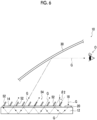
- Fig. 6 conceptually shows an example of a virtual image display apparatus according to a second aspect of the present invention.
- a virtual image display apparatus 50 according to the second aspect of the present invention has the same basic configuration as the above-described HUD 10 according to the first aspect, and includes a structure 54 on the emission side of the image light G of the emission diffraction element 14 instead of the first polarizer 16.
- a structure 54 on the emission side of the image light G of the emission diffraction element 14 instead of the first polarizer 16.
- a plurality of metal plates 52 that stand from the emission diffraction element 14 are arranged.
- the virtual image display apparatus 50 will also be referred to as the HUD 50.
- the structure 54 will also be referred to as the louver 54.
- Fig. 7 is a schematic perspective view showing the louver 54.
- the metal does not allow transmission of light (visible light). Accordingly, by setting the metal plates 52 of the louver 54 to be parallel to the traveling direction of the image light G emitted from the light guide plate 12 by the emission diffraction element 14, the image light G emitted from the light guide plate 12 transmits through the louver 54 (metal plates 52) and is incident into the windshield 30.
- the external light such as sunlight that is incident from the windshield 30 to be interference light is incident from various directions. That is, in the external light, the amount of light parallel to the image light G emitted from the light guide plate 12 is very small. Accordingly, the external light such as sunlight that is interference light is mostly shielded by the louver 54 (metal plates 52) before being incident into the emission diffraction element 14, and the amount of the light incident into the light guide plate 12 is very small.
- the external light that is incident into the light guide plate 12 to be interference light can be significantly suppressed, the interference light observed by the user O can be reduced, and glare of the image observed by the user O and dizziness of the user by the interference light can be suppressed.
- the metal plate 52 is not limited, and various well-known metal plates can be used.
- the metal plates 52 of the louver 54 have light absorbing properties.
- a method of treating the metal plates 52 to have light absorbing properties is not particularly limited, and well-known methods such as a method of providing a light absorbing layer such as a black layer or a method of providing a metal film such as gold or copper that absorbs visible light can be used.
- an antireflection film (non-reflective film) is also suitably provided on the surface of the metal plate 52.
- antireflection film provided on the surface of the metal plate 52 various well-known antireflection films such as a dielectric multi-layer film where a layer having a high refractive index and a layer having a low refractive index are alternately laminated or a moth eye film can be used.
- an angle between the metal plates 52 and the emission diffraction element 14 is not limited.
- an angle ⁇ 2 between the metal plates 52 and the normal line (two-dot chain line) of the light guide plate 12 is preferably 0° to 70°.
- the image light G emitted from the light guide plate 12 can suitably transmit through the louver 54, and external light such as sunlight that is interference light can be suitably prevented from being incident into the light guide plate 12.
- the angle ⁇ 2 between the metal plates 52 and the normal line of the light guide plate 12 is more preferably 10° to 60° and still more preferably 15° to 50°.
- an arrangement interval of the metal plates 52 is not particularly limited and may be appropriately set depending on the area of the light guide plate, the angle ⁇ 2 between the metal plates 52 and the normal line of the light guide plate 12, the height of the metal plates 52, the thickness of the metal plates 52, and the like.
- the arrangement interval of the metal plates 52 is preferably 5 to 300 mm and more preferably 10 to 100 mm.
- an arrangement direction, a tilt direction, and the like of the metal plates 52 are not limited and may be appropriately set depending on the use of the HUD 50. It is preferable that the metal plates 52 are arranged in a traveling direction of a vehicle or the like. In addition, it is preferable that the metal plates 52 are tilted to the inside of the vehicle or the like.
- the metal plates 52 may be directly arranged on the emission diffraction element 14 to configure the louver 54.
- a support having sufficient transmittance to the image light G emitted from the light guide plate 12 may be used such that the metal plates 52 are arranged on the support to configure the louver 54, and this louver 54 may be arranged on the emission surface of the emission diffraction element 14.
- Fig. 8 conceptually shows an example of a virtual image display apparatus according to a third aspect of the present invention.
- a virtual image display apparatus 60 according to the third aspect of the present invention has the same basic configuration as the above-described HUD 10 according to the first aspect, and includes an uneven structure 62 on the emission side of the image light G of the emission diffraction element 14 instead of the first polarizer 16.
- the virtual image display apparatus 60 will also be referred to as the HUD 60.
- Fig. 9 conceptually shows an example of the uneven structure.
- the uneven structure 62 shown in Fig. 9 is a sheet-like structure having unevenness on a surface opposite to the emission diffraction element 14, in which in the example shown in the drawing, an adhesive layer 68 is provided on the surface of the emission diffraction element 14, and transparent microbeads 64 are uniformly scattered and are two-dimensionally arranged and fixed on the adhesive layer 68.
- microbeads 64 are not limited, and various well-known microbeads can be used as long as they have sufficient optical transmittance.
- microbeads 64 examples include microbeads of BaO-SiO 2 -TiO 2 glass and microbeads of BaO-ZnO-TiO 2 glass. Refractive indices of the microbeads are about 1.9 to 2.2
- the particle diameter of the microbeads 64 are not limited and may be appropriately set depending on the area of the light guide plate 12 and the like.
- the particle diameter of the microbeads 64 is preferably 30 to 80 ⁇ m.
- the adhesive layer 68 that fixes the microbeads 64 is not limited, and various resins can be used as long as they have excellent adhesiveness to the microbeads 64 and sufficient transparency.
- the resins include a polyethylene resin, an acrylic resin, a urethane resin, and a silicone resin.
- the uneven structure may be directly provided on the emission diffraction element 14 as in the example shown in the drawing.
- a resin film such as a polyethylene terephthalate film, a polyethylene naphthalate film, or a TAC film is used as a support, the adhesive layer 68 is provided on a surface of the support, and the microbeads 64 are fixed to the adhesive layer 68.
- a reflective layer (light reflecting layer) 70 may be provided on an incidence side of the image light G of the uneven structure as in an uneven structure 62A shown in Fig. 10 .
- the uneven structure includes the reflective layer 70 such that retroreflection performance by the uneven structure 62A can be improved.
- external light incident into the light guide plate 12 can be further suppressed, interference light to be observed by the user O can be reduced, and glare of the image observed by the user O and dizziness of the user by the interference light can be more suitably suppressed.
- the reflective layer 70 is not limited, and various well-known reflective layers can be used as long as they have sufficient transparency.
- the reflective layer 70 may act as the adhesive layer 68.
- the reflective layer 70 may be provided on the incidence side of the image light G of the adhesive layer 68, that is, the side opposite to the microbeads 64 (uneven structure).
- the reflective layer 70 various well-known layers that allow transmission of light (visible light) can be used.
- a reflective layer where a cholesteric liquid crystal obtained by immobilizing a cholesteric liquid crystalline phase is used as a reflective material can be suitably used.
- the reflective layer 70 where the cholesteric liquid crystal is used as the reflective material reflective layers formed by various methods can be used.
- a reflective layer where a cholesteric liquid crystal pigment is dispersed in a matrix can be used.
- a coating material including the cholesteric liquid crystal pigment as a matrix, an ink, an adhesive, and the like are mixed to prepare a coating material, and this coating material is printed or applied and dried (cured) to form a reflective layer.
- the matrix has high transparency.
- cholesteric liquid crystal pigment various pigments can be used as long as they can exhibit the cholesteric liquid crystal characteristics by printing, application, or the like.
- a method of manufacturing the cholesteric liquid crystal pigment is well-known.
- JP1995-304983A JP-H7-304983A
- JP-H7-304983A describes the following method as a method of manufacturing the cholesteric liquid crystal pigment.
- a three-dimensionally crosslinkable liquid crystal material such as a liquid crystal polysiloxane is applied and aligned to a sheet substrate with a well-known method such as a method using knife coating or a method of shearing between two sheets.
- the liquid crystal material is crosslinked using thermal, photochemical, or other well-known method, and is peeled from the substrate and pulverized.
- the cholesteric liquid crystal pigment can be obtained.
- cholesteric liquid crystal pigment a commercially available product can also be used.
- the commercially available product of the cholesteric liquid crystal pigment include “HELICONE HC” (manufactured by Wacker Asahikasei Silicone Co., Ltd.).
- HELICONE HC is a flat powder having an extremely large average particle diameter with respect to the thickness, in which a helical axis of a cholesteric liquid crystal is directed to a thickness direction. Therefore, "HELICONE HC” can be disposed on an object with high aligning properties.
- cholesteric liquid crystal pigment optionally, plural kinds of pigments having different wavelengths of light components to be selectively reflected may be used.
- the thickness of the reflective layer 70 is not limited and is preferably about 10 to 100 ⁇ m.
- the particle diameter of the cholesteric liquid crystal pigment in the reflective layer 70 is too small or the concentration thereof is too low, there is a case where retroreflected light by selective reflection is not sufficiently visible at this layer thickness. Accordingly, the particle diameter and the concentration of the cholesteric liquid crystal pigment in the cholesteric liquid crystal layer may be appropriately determined such that desired retroreflection performance can be obtained.
- the particle diameter of the cholesteric liquid crystal pigment is 10 to 1000 ⁇ m, and the concentration thereof is 1 to 20 mass%.
- the reflective layer 70 is not limited as long as it is formed of a cholesteric liquid crystal, and various well-known reflective layers can be used.
- Examples of the reflective layer 70 include a reflective layer including, as a reflective material, a metal oxide-coated flaky powder (pearl pigment) having an interference color, a metal such as aluminum, a metal oxide, a colorant, or the like.
- a reflective layer including, as a reflective material, a metal oxide-coated flaky powder (pearl pigment) having an interference color, a metal such as aluminum, a metal oxide, a colorant, or the like.
- titanium dioxide powder or the like may be mixed in the reflective layer 70 to suppress the tint.
- the uneven structure used for the HUD 60 may include a planarizing film 72 that planarizes the surface of the uneven structure as in an uneven structure 62B shown in Fig. 11 .
- the uneven structure includes the planarizing film 72 from the viewpoints that, for example, the microbeads 64 can be protected and foreign matter attached to the surfaces of the microbeads 64 (uneven structure) are likely to be removed.
- the planarizing film 72 may also have an action of adjusting the focal point of the retroreflected light by the microbeads 64.
- the uneven structure 62B shown in Fig. 11 includes the reflective layer 70.
- the uneven structure including the planarizing film 72 may include the adhesive layer 68 instead of the reflective layer 70.
- the planarizing film 72 is not limited, and various well-known resin films can be used as long as they have sufficient transparency, strength, and heat resistance.
- the resin for forming the planarizing film 72 include a polyethylene resin, an acrylic resin, a urethane resin, and a silicone resin.
- a crosslinking agent may be added to the planarizing film 72 to improve the film hardness and the adhesive strength with the microbeads 64.
- a difference in refractive index between the planarizing film 72 and the uneven structure, that is, the microbeads 64 in the example shown in the drawing is small.
- the difference in refractive index between the planarizing film 72 and the uneven structure is preferably 0.3 or less, more preferably 0.15 or less, still more preferably 0.1 or less, and most preferably zero, that is, a configuration where the refractive indices thereof are the same.
- the difference in refractive index between the planarizing film 72 and the uneven structure is 0.3 or less from the viewpoints that, for example, the retroreflection performance by the uneven structure (microbeads 64) can be suitably exhibited and diffused reflection of light on the surfaces of the microbeads 64 can be prevented.
- the planarizing film 72 may be formed using a well-known method such as a coating method depending on a forming material.
- the thickness of the planarizing film 72 is not also limited and may be appropriately set depending on the forming material, the particle diameter of the microbeads 64, and the like such that the planarizing film 72 can completely embed the microbeads 64 and planarize the surfaces thereof and a required strength or the like can be obtained.
- the virtual image display apparatus can be suitably used for a HUD mounted on various transportations including a vehicle such as an automobile or a train, an airplane, or a ship.
- the virtual image display apparatus according to the embodiment of the present invention can be used not only for the transportations but also for various uses.
- a liquid crystal compound (PALIOCOLOR LC242, manufactured by BASF SE) having a photopolymerizable group and 0.1 g of a polymer surfactant (MEGAFACE F780F, manufactured by DIC Corporation) were dissolved in 5.07 g of methyl ethyl ketone (MEK) to prepare a liquid crystal solution, 1.11 g of an initiator solution was added to the liquid crystal solution, and the solution was stirred for 5 minutes to completely dissolve the components.
- MEK methyl ethyl ketone
- the initiator solution is a solution where 0.90 g of IRGACURE 907 (manufactured by Ciba Specialty Chemicals Inc.) and 0.30 g of KAYACURE DETX (manufactured by Nippon Kayaku Co., Ltd.) were dissolved in 8.80 g of MEK.
- a dichroic azo coloring agent G241 manufactured by Nagase Viita Co., Ltd.
- 0.005 g of a dichroic azo coloring agent G472 manufactured by Nagase Viita Co., Ltd.
- TAC film triacetyl cellulose film having a thickness of 40 ⁇ m was prepared.
- a 10 mass% polyvinyl alcohol (PVA, MP203, manufactured by Kuraray Co., Ltd.) aqueous solution was applied by spin coating to the prepared TAC film under conditions of a rotation speed of 500 rpm and 15 seconds, and was dried to form a PVA vertical alignment film.
- PVA polyvinyl alcohol
- the prepared polarizing film coating liquid was applied to the formed PVA vertical alignment film by spin coating under conditions of a rotation speed of 1,000 rpm and 20 seconds.
- a polarizing film where not only curable liquid crystal molecules but also the dichroic coloring agent are vertically aligned on the surface of the PVA vertical alignment film was formed on the TAC film to prepare a first polarizer.
- metal plates aluminum plates having a thickness of 1 mm, a height of 10 mm, and a width of 200 mm were prepared.
- a louver was prepared (refer to Figs. 6 and 7 ).
- the metal plates were fixed using an ultraviolet curable adhesive (UVX-5457, manufactured by Toagosei Co., Ltd.).
- a polyethylene resin was applied with a thickness of about 25 ⁇ m to an upper surface of a TAC film having a thickness of 40 ⁇ m using a comma coater.
- glass beads (refractive index: 1.92, particle diameter: 38 to 53 ⁇ m) were uniformly scattered on the polyethylene resin and were heated and dried such that lower hemispheres were embedded in and fixed to the polyethylene resin.
- a polyethylene resin for adjusting the focal point of the retroreflected light was applied to non-embedded upper hemispherical surfaces of the glass beads and was heated and dried to seal and fix the entire glass beads in the polyethylene resin.
- an uneven structure 1 including a planarizing film was prepared.
- a reflective material (cholesteric liquid crystal pigment) and 15 g of a nitrocellulose lacquer were mixed and stirred to be dispersed. As a result, a coating liquid for a reflective layer was prepared.
- cholesteric liquid crystal pigment As the reflective material (cholesteric liquid crystal pigment), HELICONE HC SCARAB XL (manufactured by Wacker Asahikasei Silicone Co., Ltd.) was used. Regarding the cholesteric liquid crystal pigment, the color of the external appearance was light yellow white, the color of light to be selectively reflected was green, and the average particle diameter was about 500 ⁇ m.
- nitrocellulose lacquer LC-21 manufactured by Gen Gen Corporation
- the coating liquid for a reflective layer was drawn down using a doctor blade with a margin of 101 ⁇ m to fixed surfaces (polyethylene resin layer surfaces) of glass beads of the uneven structure 1 prepared in advance, and was dried to prepare an uneven structure 2 including a reflective layer having a thickness of about 5 ⁇ m.
- a light guide plate shown in Fig. 2 including an incidence diffraction element, an intermediate diffraction element, and an emission diffraction element on one surface was prepared.
- the light guide plate had a thickness of 10 mm, was formed of an acrylic resin, and had a size of 200 ⁇ 200 mm.
- All the diffraction elements were holographic diffraction elements and were disposed as shown in Fig. 2 , in which the size of the incidence diffraction element was 10 ⁇ 5 mm, the size of the intermediate diffraction element was 185 ⁇ 10 mm, and the size of the emission diffraction element was 185 ⁇ 175 mm.
- the diffraction elements were fixed using an ultraviolet curable adhesive (UVX-5457, manufactured by Toagosei Co., Ltd.). Diffraction characteristics of the diffraction elements are as described above.
- the light guide plate where the diffraction elements were provided was disposed on a dashboard of an automobile.
- an image display device was provided such that an image was incident from the incidence diffraction element into the light guide plate.
- a laser scanning projection unit was used as the image display device.
- the first polarizer (Example 1), the louver (Example 2), the uneven structure 1 (Example 3), and the uneven structure 2 (Example 4) were provided on the emission diffraction elements of the light guide plates, respectively.
- four kinds of virtual image display apparatuses according to the embodiment of the present invention were prepared.
- a virtual image display apparatus including nothing on the emission diffraction element was prepared.
- a green monochromic image was displayed by the image display device, and the image (projection image) projected from a windshield was observed.
- the present invention can be suitably used for a HUD or the like mounted on a vehicle or the like.
Landscapes
- Physics & Mathematics (AREA)
- General Physics & Mathematics (AREA)
- Optics & Photonics (AREA)
- Instrument Panels (AREA)
Abstract
Description
- The present invention relates to a virtual image display apparatus. Specifically, the present invention relates to a virtual image display apparatus used for a head-up display.
- A so-called head-up display (head-up display system) that projects an image to a windshield (windshield glass) of a vehicle or the like to provide information to a driver is known. In the following description, the head-up display will also be referred to as "HUD". "HUD" is an abbreviation for the "head up display".
- The driver can obtain various information such as a map, a traveling speed, and a vehicle condition by the HUD while watching the external environment ahead of the driver without largely moving a visual line. Therefore, safer driving can be expected while obtaining various information.
-
Fig. 12 conceptually shows an example of a general HUD. - In the example shown in the drawing, a
HUD 100 is configured to include animage display unit 112, a reflectingmirror 116, aconcave mirror 118, and awindshield 126 that acts as a reflective member for reflecting and projecting image light. Theimage display unit 112 is configured to include animage display device 130 such as a liquid crystal display, and aprojection lens 131. - In the
HUD 100, theimage display unit 112, thereflecting mirror 116, and theconcave mirror 118 configure a projector of the HUD, and are accommodated in a lower portion of adashboard 120 of a vehicle such as an automobile. - In the
HUD 100, the image displayed by theimage display device 130, that is, the image light is projected by theprojection lens 131, is reflected along a predetermined optical path by the reflectingmirror 116 and theconcave mirror 118, transmits through atransmission window 124 provided in thedashboard 120, is incident into thewindshield 126, and is reflected and projected to be observed as a projection image by a user O. - In the
HUD 100, the user O observes a virtual image of the image projected to thewindshield 126. - Here, the projector used for the
HUD 100 is accommodated in the lower portion of the dashboard of the vehicle as described above, and thus is largely limited in size. Therefore, in the projector for the HUD in the related art, a required optical path length is secured by folding the optical path using a plurality of mirrors. - Therefore, the projector used for the
HUD 100 is likely to have a complicated structure. Further, as described above, a space in the lower portion of the dashboard is small, and thus the degree of freedom in the design of the projector is low. - As a HUD having a small and simple configuration where the above-described problem is solved, a HUD where a light guide plate (optical waveguide) and a diffraction element (hologram) are combined as described in
JP2021-528681A -
Fig. 13 conceptually shows an example of the HUD. - As shown in
Fig. 13 , aHUD 130 includes alight guide plate 132, anincidence diffraction element 134, and anemission diffraction element 136. - In the
HUD 130, image light G emitted from an image display device (not shown) is diffracted by theincidence diffraction element 134 and is incident into thelight guide plate 132 at an angle where total reflection occurs. The image light G incident into thelight guide plate 132 is totally reflected repeatedly and is guided (propagates) in thelight guide plate 132. - Here, the
emission diffraction element 136 is provided on an upper surface (hereinafter, also referred to as an emission surface) of thelight guide plate 132 in the drawing. A part of the light guided in thelight guide plate 132 is incident into theemission diffraction element 136, is diffracted, and is emitted upward from the emission surface. The image light G emitted from thelight guide plate 132 is incident into thewindshield 126, is reflected and projected, and is observed as a projection image by the user O, as in the above-described case. - In the
HUD 130 including thelight guide plate 132, for example, thelight guide plate 132 can be disposed above a dashboard of an automobile or the like. Therefore, the limit in size is significantly reduced as compared with theHUD 100 in the related art shown inFig. 12 . - In addition, for example, it is not necessary to fold the optical path using the mirrors, and projection light corresponding to the size of the
light guide plate 132 can be emitted. Therefore, the device configuration of the HUD can be simplified. - Here, in the
HUD 130 shown inJP2021-528681A light guide plate 132 and the diffraction element, in a case where external light such as sunlight is incident into thelight guide plate 132 and is guided and emitted, there is a problem in that the light is observed as interference light by the user O. - That is, as conceptually shown in
Fig. 14 , in theHUD 130, external light (broken line) such as sunlight transmits through thewindshield 126 and enters into the vehicle to reach thelight guide plate 132. - Here, the
emission diffraction element 136 is provided on the emission surface of thelight guide plate 132. Therefore, the external light is diffracted by theemission diffraction element 136 and is incident into thelight guide plate 132 at an angle where total reflection occurs depending on an incidence direction. - The external light incident into the
light guide plate 132 as described above is totally reflected repeatedly and is guided in thelight guide plate 132 as in the image light such that a part thereof is diffracted by theemission diffraction element 136 and is emitted from thelight guide plate 132 together with the image light. The image light and the external light emitted from thelight guide plate 132 are incident into thewindshield 126 as in the above-described case, are reflected and projected, and are observed as interference light D by the user O. As a result, glare occurs in the image observed by the user O, and the user O feels dizzy due to the interference light D. - Further, depending on an incidence angle into the
light guide plate 132, the external light that is incident into thelight guide plate 132 and is guided and emitted may be emitted from thelight guide plate 132 to directly reach the user O as the interference light D without being incident into thewindshield 126. - In order to solve the problem, in
JP2021-528681A Fig. 13 , an optical filter 138 (bandpass filter) that absorbs light having a wavelength other than a wavelength of the image light G is provided on the emission surface side of the diffraction element. - As a result, in
JP2021-528681A light guide plate 132, glare of the image observed as the interference light D by the user O is suppressed, and the dizziness of the user O caused by the interference light D is suppressed. - An object of the present invention is to provide a virtual image display apparatus for a HUD including a light guide plate and a diffraction element as in
JP2021-528681A - In order to achieve the above-described object, the present invention has the following configurations.
- [1] A virtual image display apparatus for a head-up display comprising:
- an image display device that emits image light;
- a light guide plate that guides the image light emitted from the image display device;
- an emission element that emits the image light guided in the light guide plate from the light guide plate; and
- a first polarizer that is provided on an emission side of the image light of the emission element and has an absorption axis parallel to or tilted with respect to a normal line.
- [2] The virtual image display apparatus according to [1],
in which an angle between the normal line of the first polarizer and the absorption axis of the first polarizer is 0° to 70°. - [3] The virtual image display apparatus according to [1] or [2], further comprising:
a second polarizer that is provided on the emission side of the emission element and has an absorption axis in a direction orthogonal to a normal line. - [4] The virtual image display apparatus according to any one of [1] to [3],
in which the emission element is a diffraction element. - [5] A virtual image display apparatus for a head-up display, comprising:
- an image display device that emits image light;
- a light guide plate that guides the image light emitted from the image display device;
- an emission element that emits the image light guided in the light guide plate from the light guide plate; and
- a structure that is provided on an emission side of the image light of the emission element and where a plurality of metal plates standing from the emission element are arranged.
- [6] The virtual image display apparatus according to [5],
in which an angle between a normal line of the light guide plate and the metal plate is 0° to 70°. - [7] The virtual image display apparatus according to [5] or [6],
in which the metal plate has light absorbing properties. - [8] The virtual image display apparatus according to any one of [5] to [7],
in which the emission element is a diffraction element. - [9] A virtual image display apparatus for a head-up display, comprising:
- an image display device that emits image light;
- a light guide plate that guides the image light emitted from the image display device;
- an emission element that emits the image light guided in the light guide plate from the light guide plate; and
- an uneven structure that is provided on an emission side of the image light of the emission element.
- [10] The virtual image display apparatus according to claim 9, further comprising:
a light reflecting layer that is provided between the emission element and the uneven structure. - [11] The virtual image display apparatus according to [9] or [10], further comprising:
a planarizing film that planarizes a surface of the uneven structure. - [12] The virtual image display apparatus according to [11],
in which a difference in refractive index between the planarizing film and the uneven structure is 0.3 or less. - [13] The virtual image display apparatus according to any one of [9] to [12],
in which the emission element is a diffraction element. - According to the present invention, in a virtual image display apparatus for a HUD including a light guide plate and a diffraction element, observation of interference light by a user can be suppressed using a new method.
-
-
Fig. 1 is a diagram conceptually showing an example of a virtual image display apparatus according to the present invention. -
Fig. 2 is a schematic perspective view showing the virtual image display apparatus shown inFig. 1 . -
Fig. 3 is a perspective view conceptually showing another example of the virtual image display apparatus according to the present invention. -
Fig. 4 is a diagram conceptually showing an example of a polarizer used in the virtual image display apparatus shown inFig. 1 . -
Fig. 5 is a diagram conceptually showing another example of the polarizer used in the virtual image display apparatus shown inFig. 1 . -
Fig. 6 is a diagram conceptually showing another example of the virtual image display apparatus according to the present invention. -
Fig. 7 is a schematic perspective view showing a structure used in the virtual image display apparatus shown inFig. 6 . -
Fig. 8 is a diagram conceptually showing another example of the virtual image display apparatus according to the present invention. -
Fig. 9 is a diagram conceptually showing an example of an uneven structure used in the virtual image display apparatus shown inFig. 8 . -
Fig. 10 is a diagram conceptually showing another example of the uneven structure used in the virtual image display apparatus shown inFig. 8 . -
Fig. 11 is a diagram conceptually showing another example of the uneven structure used in the virtual image display apparatus shown inFig. 8 . -
Fig. 12 is a diagram conceptually showing an example of a general virtual image display apparatus. -
Fig. 13 is a diagram conceptually showing an example of a virtual image display apparatus in the related art. -
Fig. 14 is a conceptual diagram showing an action of the virtual image display apparatus shown inFig. 13 . - Hereinafter, a virtual image display apparatus according to an embodiment of the present invention will be described in detail based on preferable examples shown in the accompanying drawings.
- In the present specification, numerical ranges represented by "to" include numerical values before and after "to" as lower limit values and upper limit values.
- In the present specification, visible light refers to light having a wavelength which can be observed by human eyes among electromagnetic waves and refers to light in a wavelength range of 380 to 780 nm. Invisible light refers to light in a wavelength range of shorter than 380 nm or longer than 780 nm. In addition, although not limited thereto, in visible light, light in a wavelength range of 420 to 490 nm refers to blue light (B light), light in a wavelength range of 495 to 570 nm refers to green light (G light), and light in a wavelength range of 620 to 750 nm refers to red light (R light). Further, although not limited thereto, infrared light refers to invisible light in a wavelength range of longer than 780 nm and 2000 nm or shorter.
- In addition, in the present invention, the description regarding parallel, perpendicular, orthogonal, or the like includes an error range generally allowed in the technical field. Specifically, parallel, perpendicular, orthogonal, and the like represent that a difference from the exact match is within a range of less than 5°. The difference from the exact match is preferably less than 4° and more preferably less than 3°.
-
Fig. 1 conceptually shows an example of a virtual image display apparatus according to a first aspect of the present invention. - A virtual
image display apparatus 10 shown inFig. 1 is a virtual image display apparatus for a HUD, and includes alight guide plate 12, anemission diffraction element 14, afirst polarizer 16, and animage display device 18. In addition, the virtualimage display apparatus 10 displays (projects) an image to a user O, for example, using awindshield 30 of a vehicle such as an automobile. Theemission diffraction element 14 is the emission element according to the embodiment of the present invention. - Although not shown in
Fig. 1 , the virtualimage display apparatus 10 further includes anincidence diffraction element 20 and an intermediate diffraction element 24 (refer toFig. 2 ). - The virtual
image display apparatus 10 is basically the same as the virtual image display apparatus (device that forms a virtual image (VB)) described inJP2021-528681A first polarizer 16 instead of theoptical filter 138 that absorbs external light such as sunlight to suppress interference light. - Accordingly, as in the above-described
HUD 130 shown inFig. 13 , in the virtualimage display apparatus 10, the image light G emitted from theimage display device 18 is also diffracted by theincidence diffraction element 20 to be incident into thelight guide plate 12 at an angle where total reflection occurs. The image light G incident into thelight guide plate 12 is totally reflected repeatedly and is guided (propagates) in thelight guide plate 12. - The
emission diffraction element 14 is bonded to an emission surface (upper surface in the drawing) of thelight guide plate 12. A part of the light guided in thelight guide plate 12 is incident into theemission diffraction element 14, is diffracted, and is emitted from thelight guide plate 12. The image light emitted from thelight guide plate 12 is incident into thewindshield 30, is reflected and projected, and is observed by the user O. The user O observes a virtual image of the image projected to thewindshield 30 as in the well-known HUD (virtual image display apparatus). - In the following description, the virtual
image display apparatus 10 will also be referred to as theHUD 10. -
Fig. 2 is a schematic perspective view showing thelight guide plate 12. - As shown in
Fig. 2 , in thelight guide plate 12, a main surface has a rectangular plate shape, and theincidence diffraction element 20 is provided in the vicinity of one corner portion of one main surface. In addition, theintermediate diffraction element 24 that is long in a lateral direction is provided near theincidence diffraction element 20 and in the vicinity of an end part in a longitudinal direction. Further, in thelight guide plate 12, in a region of the main surface where theincidence diffraction element 20 and theintermediate diffraction element 24 are not provided, theemission diffraction element 14 is provided to cover substantially the entire surface. - The main surface is the maximum surface of a plate-like material (a sheet-like material, a film, or a layer), that is, both surfaces of the plate-like material in a thickness direction.
- In addition, in the following description, for convenience of description, it is assumed that a vertical direction on the paper plane of the
light guide plate 12 is a Y direction and a horizontal direction on the paper plane is an X direction. - As in the
HUD 130 shown inFig. 13 , theincidence diffraction element 20 is a diffraction element for causing the image light G emitted from theimage display device 18 to be incident into thelight guide plate 12. - The
incidence diffraction element 20 diffracts the image light G emitted from theimage display device 18 to be guided in the Y direction at an angle where total reflection occurs in thelight guide plate 12. - As indicated by arrows, the image light G incident into the
light guide plate 12 by theincidence diffraction element 20 is guided in the Y direction in the vicinity of an end part in the X direction while being totally reflected repeatedly in thelight guide plate 12, and a part of the light is incident into theintermediate diffraction element 24. Due to the guidance of the image light G in the Y direction, the image light (image) emitted from theimage display device 18 is enlarged in the Y direction. - The
intermediate diffraction element 24 is a diffraction element that deflects a light guide direction of the image light G in thelight guide plate 12. A part of the image light G that is guided in the Y direction in the vicinity of an end part in the X direction is incident into theintermediate diffraction element 24, and is diffracted in the X direction of thelight guide plate 12 at an angle where total reflection occurs in thelight guide plate 12, that is, to theemission diffraction element 14 as indicated by arrows. InFig. 2 , although only one arrow is shown, the diffraction of the image light G from theintermediate diffraction element 24 to theemission diffraction element 14 is performed over the entire range in a longitudinal direction of theintermediate diffraction element 24 that is long in the Y direction of thelight guide plate 12. - The image light G diffracted by the
intermediate diffraction element 24 is guided in the X direction while being totally reflected in thelight guide plate 12, and a part of the light is incident into theemission diffraction element 14. - As in the
HUD 130 shown inFig. 13 , theemission diffraction element 14 is a diffraction element for emitting the image light G from thelight guide plate 12. A part of the image light G guided in the X direction while being totally reflected in thelight guide plate 12 is incident into theemission diffraction element 14 and is diffracted such that the image light G is emitted from thelight guide plate 12 as indicated by an arrow moving upward in the drawing and shown inFig. 1 above. In addition, due to the guidance of the image light G in the X direction, the image light (image) emitted from theimage display device 18 is enlarged in the X direction. - As described above, the image light G emitted from the
light guide plate 12 is incident into thewindshield 30, is reflected and projected, and is observed by the user O. InFig. 2 , although only one arrow of the image light is shown, the emission of the image light from thelight guide plate 12 by theemission diffraction element 14 is performed over the entire surface of theemission diffraction element 14. - In the example shown in
Fig. 2 , onelight guide plate 12 is provided. - However, the present invention is not limited to this configuration. For example, in a case where the
HUD 10 displays a full color image including red (R), green (G), and blue (B), as conceptually shown inFig. 3 , alight guide plate 12R that guides image light of R, alight guide plate 12G that guides image light of G, and alight guide plate 12B that guides image light of B may be provided according to each of the colors. - The lamination order of the light guide plates is not limited to the example of
Fig. 3 . - In each of the
light guide plate 12R, thelight guide plate 12G, and thelight guide plate 12B, theincidence diffraction element 20, theintermediate diffraction element 24, and theemission diffraction element 14 are provided. - In the diffraction elements provided in each of the light guide plates, at least the
incidence diffraction element 20 and theemission diffraction element 14 have wavelength dependence (wavelength selectivity) diffract only the image light of the corresponding light to be incident into the light guide plate. Further, it is preferable that theintermediate diffraction element 24 has wavelength dependence and diffracts only the image light of the corresponding light. In this case, the diffraction element into which monochromatic light is incident does not need to have wavelength dependence. That is, in the present example, the diffraction element where thelight guide plate 12B is provided does not need to have wavelength dependence. - However, in the configuration including a plurality of light guide plates, it is preferable that all of the diffraction elements provided in each of the light guide plates have wavelength dependence.
- In the example shown in
Fig. 3 , the image light emitted from theimage display device 18 is deflected to thelight guide plate 12R by amirror 34. - In the image light deflected by the
mirror 34, the R image light is diffracted by theincidence diffraction element 20 provided in thelight guide plate 12R to be incident into thelight guide plate 12R. The G image light and the B image light transmit through theincidence diffraction element 20. - In addition, the G image light is diffracted by the
incidence diffraction element 20 provided in thelight guide plate 12G to be incident into thelight guide plate 12G The B image light transmits through the incidence diffraction element. - Further, the B image light is diffracted by the
incidence diffraction element 20 provided in thelight guide plate 12B to be incident into thelight guide plate 12B. - The image light incident into each of the corresponding light guide plates is guided in the Y direction as in
Fig. 2 , is deflected in the X direction as the light guide direction by theintermediate diffraction element 24, and is emitted from the light guide plate to thewindshield 30 by theemission diffraction element 14. The Y direction is a lateral direction of the light guide plate, and the X direction is a longitudinal direction of the light guide plate. - Here, the B image light emitted from the
light guide plate 12B transmits through theemission diffraction elements 14 provided in thelight guide plate 12G and thelight guide plate 12R, and is emitted to thewindshield 30. In addition, the G image light emitted from thelight guide plate 12G transmits through theemission diffraction elements 14 provided in thelight guide plate 12R, and is emitted to thewindshield 30. - In the HUD 10 (virtual image display apparatus) according to the embodiment of the present invention, the
image display device 18, thelight guide plate 12, and each of the diffraction elements are not particularly limited, and various well-known elements can be used. - For example, as the
image display device 18, various well-known image display devices such as a liquid crystal display device, a liquid crystal on silicon (LCOS), an organic electroluminescence (organic EL) display, or digital light processing (DLP) using a digital micromirror device (DMD) can be used. Optionally, a projection lens may be combined with these image display devices. - As the
light guide plate 12, various well-known light guide plates used for a backlight unit of a liquid crystal display device, AR glasses, or the like, for example, a light guide plate formed of glass or a light guide plate formed of a plastic such as an acrylic resin can be used. - Further, as the diffraction element, various well-known diffraction elements such as a liquid crystal diffraction element, a holographic diffraction element (hologram), a volume hologram diffraction element, or a surface relief diffraction element can be used.
- The diffraction element may be a reflective type or a transmissive type.
- In addition, each of the diffraction elements may be bonded to the
light guide plate 12 with a well-known method using an optical clear adhesive (OCA). - In the
HUD 10 in the example shown in the drawing, thediffraction element 14 is used as the emission element for emitting the image light G from thelight guide plate 12. However, the present invention is not limited to this configuration. - For example, as shown in
Fig. 4 ofJP2021-528681A light guide plate 12, a plurality of half mirrors that are tilted with respect to the main surface may be provided in the light guide direction of the image light G to function as the emission element that emits the image light G from the light guide plate. - Regarding this point, the same can be applied to the other aspects of the present invention.
- In the
HUD 10 in the example shown in the drawing, the image light G is incident into thewindshield 30 and is reflected and projected. However, the present invention is not limited to this example. - That is, in the HUD 10 (virtual image display apparatus) according to the embodiment of the present invention, a combiner such as a half mirror for reflecting an image may be used such that the image light G emitted from the
light guide plate 12 is incident into the combiner and is reflected and projected. In addition, a combiner for reflecting the image light G may be provided in thewindshield 30. - As shown in
Fig. 1 , theHUD 10 according to the first aspect of the present invention may include thefirst polarizer 16 on the emission side of the image light G of theemission diffraction element 14. Thefirst polarizer 16 is a polarizer having an absorption axis parallel to or tilted with respect to a normal line. - The normal line is a line orthogonal to a surface and, in the case of the
first polarizer 16, is a line orthogonal to the main surface of thefirst polarizer 16 and parallel to the thickness direction. -
Fig. 4 conceptually shows an example of thefirst polarizer 16. In thefirst polarizer 16 illustrated inFig. 4 , adichroic substance 40 is used as the absorption axis. Therefore, a major axis of thedichroic substance 40 is aligned to be parallel to (vertical alignment) or tilted with respect to the normal line. - In the
HUD 10 according to the embodiment of the present invention, by providing thefirst polarizer 16 on the emission side of the image light G of theemission diffraction element 14, incidence of external light such as sunlight into thelight guide plate 12 is suppressed, and observation of the external light as interference light by the user O is suppressed. - As described above with reference to
Fig. 14 , in the HUD including the light guide plate and the diffraction elements, when external light such as sunlight reaches the light guide plate, the external light is diffracted by the emission diffraction element provided on the emission surface of the light guide plate, and a part of the external light is incident at an angle where total reflection occurs. - This external light is guided in the light guide plate as in the image light, is diffracted by the emission diffraction element, and is emitted from the light guide plate. Next, together with the image light, the external light is incident into the windshield, is reflected and projected or is directly emitted from the light guide plate to the user O, and is observed as interference light by the user O. As a result, glare occurs in the image observed by the user O, and the user O feels dizzy due to the interference light.
- On the other hand, the
HUD 10 according to the embodiment of the present invention includes thefirst polarizer 16 on the emission surface side of theemission diffraction element 14. As described above, thefirst polarizer 16 aligns the absorption axis, that is, the major axis of thedichroic substance 40 to be parallel to (vertical alignment) or tilted with respect to the normal line of thefirst polarizer 16. - In the
first polarizer 16 where thedichroic substance 40 is used as the absorption axis, a direction of the major axis of thedichroic substance 40 is the absorption axis. In a case where light incident into thefirst polarizer 16 travels in a direction parallel (substantially parallel) to the absorption axis, the light transmits through thefirst polarizer 16. - On the other hand, in a case where light incident into the
first polarizer 16 travels in a direction intersecting with the absorption axis, the light is absorbed by the absorption axis, that is, by the dichroic substance in the example shown in the drawing. - Therefore, by setting the major axis of the
dichroic substance 40, that is, the absorption axis of thefirst polarizer 16 to be parallel to the traveling direction of the image light G emitted from thelight guide plate 12, the image light G emitted from thelight guide plate 12 transmits through thefirst polarizer 16 and is incident into thewindshield 30. - On the other hand, the external light such as sunlight that is incident from the
windshield 30 to be interference light is incident from various directions. That is, in the external light as the interference light, the amount of light parallel to the image light G emitted from thelight guide plate 12 is very small. Accordingly, the external light such as sunlight that is interference light is mostly absorbed by thefirst polarizer 16 before being incident into theemission diffraction element 14, and the amount of the external light incident into thelight guide plate 12 is very small. - As a result, in the
HUD 10 according to the embodiment of the present invention including thefirst polarizer 16, the external light that is incident into thelight guide plate 12 to be interference light can be significantly suppressed, the interference light observed by the user O can be reduced, and glare of the image observed by the user O and dizziness of the user by the interference light can be suppressed. - In the
first polarizer 16, thedichroic substance 40 is used as the absorption axis. - The dichroic substance (dichroic coloring agent) is not particularly limited, and examples thereof include an azo coloring agent and an anthraquinone coloring agent. The dichroic substances may be used alone or in combination of two or more kinds.
- In the present invention, the dichroic substance is defined as a compound having a function of absorbing light.
- The dichroic substance may have any of an absorption maximum or an absorption band and preferably has an absorption maximum in any of a yellow (Y) range, a magenta (M) range, or a cyan (C) range.
- In addition, two or more kinds of dichroic substances may be used. In this case, it is preferable that a mixture of dichroic substances having an absorption maximum in the Y range, the M range, and the C range is used, and it is more preferable that dichroic substances are mixed and used to absorb all the light components in a visible range (380 to 780 nm). Here, the yellow range refers to a wavelength range of 420 to 490 nm, the magenta range refers to a wavelength range of 495 to 570 nm, and the cyan range refers to a wavelength range of 620 to 750 nm.
- Next, a chromophore used in the dichroic substance will be described.
- The chromophore of the dichroic substance is not particularly limited, and can be appropriately selected depending on the purpose. Examples of the chromophore include an azo coloring agent, an anthraquinone coloring agent, a perylene coloring agent, a merocyanine coloring agent, an azomethine coloring agent, a phthaloperylene coloring agent, an indigo coloring agent, an azulene coloring agent, a dioxazine coloring agent, a polythiophene coloring agent, and a phenoxazine coloring agent. Among these, an azo coloring agent, an anthraquinone coloring agent, or a phenoxazine coloring agent is preferable. In particular, an anthraquinone coloring agent or a phenoxazone coloring agent (for example, phenoxazin-3-one) is more preferable.
- Specific examples of the coloring agent include the compounds described in paragraphs "0022" to "0075" of
JP2008-275976A - The absorption axis of the
first polarizer 16 is not limited to the dichroic substance, and various birefringent materials can be used. Examples of the birefringent material include anisotropic metal nanoparticles and carbon nanotubes. However, as the birefringent material, thedichroic substance 40 shown inFig. 4 is more suitably used. - The anisotropic metal nanoparticles are rod-like metal fine particles having a nanosize of several nanometers to 100 nm. The rod-like metal fine particles are particles having an aspect ratio (major axis length/minor axis length) of 1.5 or more.
- The anisotropic metal nanoparticles exhibit surface plasmon resonance and exhibit absorption in an ultraviolet to infrared range. In the anisotropic metal nanoparticles having a minor axis length of 1 to 50 nm, a major axis length of 10 to 1,000 nm, and an aspect ratio of 1.5 or more, an absorption position can vary between a minor axis direction and a major axis direction. Therefore, a polarizer where the anisotropic metal nanoparticles are aligned to be parallel to or tilted with respect to the normal line of the film is an anisotropic absorbing film.
- The carbon nanotubes are elongated tubular carbon having a fiber diameter of 1 to 1,000 nm, a length of 0.1 to 1,000 µm, and an aspect ratio of 100 to 10,000.
- As a method of preparing the carbon nanotubes, for example, an arc discharge method, a laser vaporization method, a thermal CVD method, or a plasma CVD method is known. As the carbon nanotubes obtained using an arc discharge method or a laser vaporization method, single wall carbon nanotubes (Single Wall Nanotube: SWNT) including one graphene sheet and multi wall carbon nanotubes (Maluti Wall Nanotube: MWNT) including a plurality of graphene sheets are present.
- In addition, in the thermal CVD method and the plasma CVD method, MWNT can be mainly prepared. SWNT has a structure in which one graphene sheet is wound in a tubular shape, the graphene sheet having a structure where carbon atoms are linked in a hexagonal shape through the strongest bond called a SP2 bond.
- In the
first polarizer 16, various alignment states can be used as long as the absorption axis is parallel to or tilted with respect to the normal line of thefirst polarizer 16. In thefirst polarizer 16, an angle θ1 between the absorption axis and the normal line (two-dot chain line) of thefirst polarizer 16 is preferably 0° to 70°. - By setting the angle of the absorption axis to be in the above-described range, the image light G emitted from the
light guide plate 12 can suitably transmit through thefirst polarizer 16, and interference light such as sunlight can be suitably prevented from being incident into thelight guide plate 12. - In the
first polarizer 16, the angle θ1 between the absorption axis and the normal line of thefirst polarizer 16 is more preferably 10° to 60° and still more preferably 15° to 50°. - Here, a direction (alignment direction) of the absorption axis in the
first polarizer 16 can be verified, for example, by observing a cross section of the polarizer with a transmission electron microscope (TEM). - As conceptually shown in
Fig. 5 , it is preferable that theHUD 10 includes asecond polarizer 42 in addition to thefirst polarizer 16. - In the
second polarizer 42, thedichroic substance 40, that is, an absorption axis is aligned in a direction orthogonal to a normal line of thesecond polarizer 42. That is, in thesecond polarizer 42, thedichroic substance 40, that is, the absorption axis is horizontally aligned. The lamination order of thefirst polarizer 16 and thesecond polarizer 42 may be reversed. - The external light such as sunlight that is interference light may transmit through the
windshield 30 to be polarized light. - By providing the
second polarizer 42 where thedichroic substance 40 is horizontally aligned, the polarized light that is incident into thesecond polarizer 42 to be interference light can be absorbed. In addition, even in a case where the light as interference light is unpolarized light, half of the external light that is incident into thesecond polarizer 42 to be interference light can be absorbed. - The polarizer may be prepared using a well-known method. Examples of the method include a method of using a transparent resin film as a support and forming a polarizing film on the support with a metal nanorod deposition method in a liquid crystal alignment field, a guest-host liquid crystal method, an anodized alumina method, or the like. In particular, the guest-host liquid crystal method is preferable. As the support, a low-retardation resin film, for example, a cellulose acylate film such as a triacetyl cellulose (TAC) film is preferably used.
- Examples of the above-described method include a method described in paragraphs "0087" to "0108" of
JP2008-275976A -
Fig. 6 conceptually shows an example of a virtual image display apparatus according to a second aspect of the present invention. - A virtual image display apparatus 50 according to the second aspect of the present invention has the same basic configuration as the above-described
HUD 10 according to the first aspect, and includes astructure 54 on the emission side of the image light G of theemission diffraction element 14 instead of thefirst polarizer 16. In thestructure 54, a plurality ofmetal plates 52 that stand from theemission diffraction element 14 are arranged. - Hereinafter, the virtual image display apparatus 50 will also be referred to as the HUD 50. In addition, the
structure 54 will also be referred to as thelouver 54.Fig. 7 is a schematic perspective view showing thelouver 54. - The metal does not allow transmission of light (visible light). Accordingly, by setting the
metal plates 52 of thelouver 54 to be parallel to the traveling direction of the image light G emitted from thelight guide plate 12 by theemission diffraction element 14, the image light G emitted from thelight guide plate 12 transmits through the louver 54 (metal plates 52) and is incident into thewindshield 30. - In addition, as described above, the external light such as sunlight that is incident from the
windshield 30 to be interference light is incident from various directions. That is, in the external light, the amount of light parallel to the image light G emitted from thelight guide plate 12 is very small. Accordingly, the external light such as sunlight that is interference light is mostly shielded by the louver 54 (metal plates 52) before being incident into theemission diffraction element 14, and the amount of the light incident into thelight guide plate 12 is very small. - As a result, in the HUD 50 according to the embodiment of the present invention including the
louver 54, the external light that is incident into thelight guide plate 12 to be interference light can be significantly suppressed, the interference light observed by the user O can be reduced, and glare of the image observed by the user O and dizziness of the user by the interference light can be suppressed. - In the
louver 54, themetal plate 52 is not limited, and various well-known metal plates can be used. For example, a metal plate consisting of a metal having excellent heat resistance, such as stainless steel or aluminum, is suitably used. - It is preferable that the
metal plates 52 of thelouver 54 have light absorbing properties. - A method of treating the
metal plates 52 to have light absorbing properties is not particularly limited, and well-known methods such as a method of providing a light absorbing layer such as a black layer or a method of providing a metal film such as gold or copper that absorbs visible light can be used. - In addition, an antireflection film (non-reflective film) is also suitably provided on the surface of the
metal plate 52. - As the antireflection film provided on the surface of the
metal plate 52, various well-known antireflection films such as a dielectric multi-layer film where a layer having a high refractive index and a layer having a low refractive index are alternately laminated or a moth eye film can be used. - Further, by treating the surface of the
metal plate 52 to have an uneven shape (roughening treatment), external light that is reflected from themetal plate 52 to be interference light is scattered and is not likely to be incident into thelight guide plate 12, which is suitable. - In the
louver 54, as long as themetal plates 52 stand from theemission diffraction element 14, for example, an angle between themetal plates 52 and theemission diffraction element 14 is not limited. - In the
louver 54, an angle θ2 between themetal plates 52 and the normal line (two-dot chain line) of thelight guide plate 12 is preferably 0° to 70°. - By setting the angle of the
metal plates 52 to be in the above-described range, the image light G emitted from thelight guide plate 12 can suitably transmit through thelouver 54, and external light such as sunlight that is interference light can be suitably prevented from being incident into thelight guide plate 12. - In the
louver 54, the angle θ2 between themetal plates 52 and the normal line of thelight guide plate 12 is more preferably 10° to 60° and still more preferably 15° to 50°. - In the
louver 54, an arrangement interval of themetal plates 52 is not particularly limited and may be appropriately set depending on the area of the light guide plate, the angle θ2 between themetal plates 52 and the normal line of thelight guide plate 12, the height of themetal plates 52, the thickness of themetal plates 52, and the like. - The arrangement interval of the
metal plates 52 is preferably 5 to 300 mm and more preferably 10 to 100 mm. - In addition, in the
louver 54, an arrangement direction, a tilt direction, and the like of themetal plates 52 are not limited and may be appropriately set depending on the use of the HUD 50. It is preferable that themetal plates 52 are arranged in a traveling direction of a vehicle or the like. In addition, it is preferable that themetal plates 52 are tilted to the inside of the vehicle or the like. - In the HUD 50, as shown in
Fig. 7 , themetal plates 52 may be directly arranged on theemission diffraction element 14 to configure thelouver 54. - Alternatively, a support having sufficient transmittance to the image light G emitted from the
light guide plate 12 may be used such that themetal plates 52 are arranged on the support to configure thelouver 54, and thislouver 54 may be arranged on the emission surface of theemission diffraction element 14. -
Fig. 8 conceptually shows an example of a virtual image display apparatus according to a third aspect of the present invention. - A virtual
image display apparatus 60 according to the third aspect of the present invention has the same basic configuration as the above-describedHUD 10 according to the first aspect, and includes anuneven structure 62 on the emission side of the image light G of theemission diffraction element 14 instead of thefirst polarizer 16. - Hereinafter, the virtual
image display apparatus 60 will also be referred to as theHUD 60. -
Fig. 9 conceptually shows an example of the uneven structure. - The
uneven structure 62 shown inFig. 9 is a sheet-like structure having unevenness on a surface opposite to theemission diffraction element 14, in which in the example shown in the drawing, anadhesive layer 68 is provided on the surface of theemission diffraction element 14, andtransparent microbeads 64 are uniformly scattered and are two-dimensionally arranged and fixed on theadhesive layer 68. - By including the
uneven structure 62 on the emission side of the image light G of theemission diffraction element 14, external light such as sunlight that is interference light is incident into themicrobeads 64 of theuneven structure 62, returns to the incidence direction by retroreflection, and are scattered. As a result, likewise, external light incident into thelight guide plate 12 can be significantly suppressed, interference light to be observed by the user O can be reduced, and glare of the image observed by the user O and dizziness of the user by the interference light can be suppressed. - The microbeads 64 (micro grains) are not limited, and various well-known microbeads can be used as long as they have sufficient optical transmittance.
- Examples of the
microbeads 64 include microbeads of BaO-SiO2-TiO2 glass and microbeads of BaO-ZnO-TiO2 glass. Refractive indices of the microbeads are about 1.9 to 2.2 - In addition, the particle diameter of the
microbeads 64 are not limited and may be appropriately set depending on the area of thelight guide plate 12 and the like. The particle diameter of themicrobeads 64 is preferably 30 to 80 µm. - The
adhesive layer 68 that fixes themicrobeads 64 is not limited, and various resins can be used as long as they have excellent adhesiveness to themicrobeads 64 and sufficient transparency. Examples of the resins include a polyethylene resin, an acrylic resin, a urethane resin, and a silicone resin. - The uneven structure may be directly provided on the
emission diffraction element 14 as in the example shown in the drawing. However, in the uneven structure, it is preferable that a resin film such as a polyethylene terephthalate film, a polyethylene naphthalate film, or a TAC film is used as a support, theadhesive layer 68 is provided on a surface of the support, and themicrobeads 64 are fixed to theadhesive layer 68. - In the uneven structure used for the
HUD 60 according to the embodiment of the present invention, a reflective layer (light reflecting layer) 70 may be provided on an incidence side of the image light G of the uneven structure as in anuneven structure 62A shown inFig. 10 . - The uneven structure includes the
reflective layer 70 such that retroreflection performance by theuneven structure 62A can be improved. As a result, external light incident into thelight guide plate 12 can be further suppressed, interference light to be observed by the user O can be reduced, and glare of the image observed by the user O and dizziness of the user by the interference light can be more suitably suppressed. - The
reflective layer 70 is not limited, and various well-known reflective layers can be used as long as they have sufficient transparency. - In this case, the
reflective layer 70 may act as theadhesive layer 68. In addition, thereflective layer 70 may be provided on the incidence side of the image light G of theadhesive layer 68, that is, the side opposite to the microbeads 64 (uneven structure). - As the
reflective layer 70, various well-known layers that allow transmission of light (visible light) can be used. For example, a reflective layer where a cholesteric liquid crystal obtained by immobilizing a cholesteric liquid crystalline phase is used as a reflective material can be suitably used. - As the
reflective layer 70 where the cholesteric liquid crystal is used as the reflective material, reflective layers formed by various methods can be used. For example, a reflective layer where a cholesteric liquid crystal pigment is dispersed in a matrix can be used. Specifically, for example, a coating material including the cholesteric liquid crystal pigment as a matrix, an ink, an adhesive, and the like are mixed to prepare a coating material, and this coating material is printed or applied and dried (cured) to form a reflective layer. - It is preferable that the matrix has high transparency.
- As the cholesteric liquid crystal pigment, various pigments can be used as long as they can exhibit the cholesteric liquid crystal characteristics by printing, application, or the like. A method of manufacturing the cholesteric liquid crystal pigment is well-known.
- For example,
JP1995-304983A JP-H7-304983A - As the cholesteric liquid crystal pigment, a commercially available product can also be used. Examples of the commercially available product of the cholesteric liquid crystal pigment include "HELICONE HC" (manufactured by Wacker Asahikasei Silicone Co., Ltd.). "HELICONE HC" is a flat powder having an extremely large average particle diameter with respect to the thickness, in which a helical axis of a cholesteric liquid crystal is directed to a thickness direction. Therefore, "HELICONE HC" can be disposed on an object with high aligning properties.
- As the cholesteric liquid crystal pigment, optionally, plural kinds of pigments having different wavelengths of light components to be selectively reflected may be used.
- The thickness of the
reflective layer 70 is not limited and is preferably about 10 to 100 µm. - In a case where the particle diameter of the cholesteric liquid crystal pigment in the
reflective layer 70 is too small or the concentration thereof is too low, there is a case where retroreflected light by selective reflection is not sufficiently visible at this layer thickness. Accordingly, the particle diameter and the concentration of the cholesteric liquid crystal pigment in the cholesteric liquid crystal layer may be appropriately determined such that desired retroreflection performance can be obtained. Although depending on the kind of the cholesteric liquid crystal pigment, for example, the particle diameter of the cholesteric liquid crystal pigment is 10 to 1000 µm, and the concentration thereof is 1 to 20 mass%. - The
reflective layer 70 is not limited as long as it is formed of a cholesteric liquid crystal, and various well-known reflective layers can be used. - Examples of the
reflective layer 70 include a reflective layer including, as a reflective material, a metal oxide-coated flaky powder (pearl pigment) having an interference color, a metal such as aluminum, a metal oxide, a colorant, or the like. - In addition, optionally, titanium dioxide powder or the like may be mixed in the
reflective layer 70 to suppress the tint. - The uneven structure used for the
HUD 60 according to the embodiment of the present invention may include aplanarizing film 72 that planarizes the surface of the uneven structure as in anuneven structure 62B shown inFig. 11 . - It is preferable that the uneven structure includes the
planarizing film 72 from the viewpoints that, for example, themicrobeads 64 can be protected and foreign matter attached to the surfaces of the microbeads 64 (uneven structure) are likely to be removed. In addition, theplanarizing film 72 may also have an action of adjusting the focal point of the retroreflected light by themicrobeads 64. - The
uneven structure 62B shown inFig. 11 includes thereflective layer 70. The uneven structure including theplanarizing film 72 may include theadhesive layer 68 instead of thereflective layer 70. - The
planarizing film 72 is not limited, and various well-known resin films can be used as long as they have sufficient transparency, strength, and heat resistance. Preferable examples of the resin for forming theplanarizing film 72 include a polyethylene resin, an acrylic resin, a urethane resin, and a silicone resin. - A crosslinking agent may be added to the
planarizing film 72 to improve the film hardness and the adhesive strength with themicrobeads 64. - In the present invention, it is preferable that a difference in refractive index between the
planarizing film 72 and the uneven structure, that is, themicrobeads 64 in the example shown in the drawing is small. - The difference in refractive index between the
planarizing film 72 and the uneven structure is preferably 0.3 or less, more preferably 0.15 or less, still more preferably 0.1 or less, and most preferably zero, that is, a configuration where the refractive indices thereof are the same. - It is preferable that the difference in refractive index between the
planarizing film 72 and the uneven structure is 0.3 or less from the viewpoints that, for example, the retroreflection performance by the uneven structure (microbeads 64) can be suitably exhibited and diffused reflection of light on the surfaces of themicrobeads 64 can be prevented. - The
planarizing film 72 may be formed using a well-known method such as a coating method depending on a forming material. - In addition, the thickness of the
planarizing film 72 is not also limited and may be appropriately set depending on the forming material, the particle diameter of themicrobeads 64, and the like such that theplanarizing film 72 can completely embed themicrobeads 64 and planarize the surfaces thereof and a required strength or the like can be obtained. - The virtual image display apparatus according to the embodiment of the present invention can be suitably used for a HUD mounted on various transportations including a vehicle such as an automobile or a train, an airplane, or a ship.
- The virtual image display apparatus according to the embodiment of the present invention can be used not only for the transportations but also for various uses.
- Hereinabove, the virtual image display apparatus according to the embodiment of the present invention has been described in detail. However, the present invention is not limited to the above-described examples, and various improvements and modifications can be made within a range not departing from the scope of the present invention.
- Hereinafter, the present invention will be described in more detail with reference to examples of the present invention. The materials, the reagents, the amounts of substances and the proportions of the substances, the operations, and the like shown in the following Examples, Comparative Examples, and Preparation Examples can be appropriately changed within a range not departing from the scope of the present invention. Accordingly, the scope of the present invention is not limited to the following Examples and Reference Examples.
- 3.04 g of a liquid crystal compound (PALIOCOLOR LC242, manufactured by BASF SE) having a photopolymerizable group and 0.1 g of a polymer surfactant (MEGAFACE F780F, manufactured by DIC Corporation) were dissolved in 5.07 g of methyl ethyl ketone (MEK) to prepare a liquid crystal solution, 1.11 g of an initiator solution was added to the liquid crystal solution, and the solution was stirred for 5 minutes to completely dissolve the components. The initiator solution is a solution where 0.90 g of IRGACURE 907 (manufactured by Ciba Specialty Chemicals Inc.) and 0.30 g of KAYACURE DETX (manufactured by Nippon Kayaku Co., Ltd.) were dissolved in 8.80 g of MEK.
- Next, 0.023 g of a dichroic azo coloring agent G241 (manufactured by Nagase Viita Co., Ltd.) and 0.005 g of a dichroic azo coloring agent G472 (manufactured by Nagase Viita Co., Ltd.) were added to the prepared solution, and the solution was ultrasonically dispersed for 5 minutes to prepare a polarizing film coating liquid.
- On the other hand, using the same method as that of Example 20 of
WO2014/112575A , a triacetyl cellulose film (TAC film) having a thickness of 40 µm was prepared. - A 10 mass% polyvinyl alcohol (PVA, MP203, manufactured by Kuraray Co., Ltd.) aqueous solution was applied by spin coating to the prepared TAC film under conditions of a rotation speed of 500 rpm and 15 seconds, and was dried to form a PVA vertical alignment film.
- Next, the prepared polarizing film coating liquid was applied to the formed PVA vertical alignment film by spin coating under conditions of a rotation speed of 1,000 rpm and 20 seconds.
- Next, by heating the PVA vertical alignment film for 2 minutes in a constant-temperature tank set to 90°C and irradiating (200 W, 73 mJ/cm2) the PVA vertical alignment film with ultraviolet light using a mercury xenon lamp in the heated state, a polarizing film where not only curable liquid crystal molecules but also the dichroic coloring agent are vertically aligned on the surface of the PVA vertical alignment film was formed on the TAC film to prepare a first polarizer.
- As metal plates, aluminum plates having a thickness of 1 mm, a height of 10 mm, and a width of 200 mm were prepared.
- By arranging the metal plates on an acrylic transparent substrate at an interval of 10 mm to stand in parallel, a louver was prepared (refer to
Figs. 6 and7 ). The metal plates were fixed using an ultraviolet curable adhesive (UVX-5457, manufactured by Toagosei Co., Ltd.). - A polyethylene resin was applied with a thickness of about 25 µm to an upper surface of a TAC film having a thickness of 40 µm using a comma coater.
- Before completely curing the polyethylene resin, glass beads (refractive index: 1.92, particle diameter: 38 to 53 µm) were uniformly scattered on the polyethylene resin and were heated and dried such that lower hemispheres were embedded in and fixed to the polyethylene resin.
- Further, a polyethylene resin for adjusting the focal point of the retroreflected light was applied to non-embedded upper hemispherical surfaces of the glass beads and was heated and dried to seal and fix the entire glass beads in the polyethylene resin. As a result, an uneven structure 1 including a planarizing film was prepared.
- 1 g of a reflective material (cholesteric liquid crystal pigment) and 15 g of a nitrocellulose lacquer were mixed and stirred to be dispersed. As a result, a coating liquid for a reflective layer was prepared.
- As the reflective material (cholesteric liquid crystal pigment), HELICONE HC SCARAB XL (manufactured by Wacker Asahikasei Silicone Co., Ltd.) was used. Regarding the cholesteric liquid crystal pigment, the color of the external appearance was light yellow white, the color of light to be selectively reflected was green, and the average particle diameter was about 500 µm.
- In addition, as the nitrocellulose lacquer, nitrocellulose lacquer LC-21 (manufactured by Gen Gen Corporation) was used.
- The coating liquid for a reflective layer was drawn down using a doctor blade with a margin of 101 µm to fixed surfaces (polyethylene resin layer surfaces) of glass beads of the uneven structure 1 prepared in advance, and was dried to prepare an uneven structure 2 including a reflective layer having a thickness of about 5 µm.
- A light guide plate shown in
Fig. 2 including an incidence diffraction element, an intermediate diffraction element, and an emission diffraction element on one surface was prepared. - The light guide plate had a thickness of 10 mm, was formed of an acrylic resin, and had a size of 200 × 200 mm.
- All the diffraction elements were holographic diffraction elements and were disposed as shown in
Fig. 2 , in which the size of the incidence diffraction element was 10 × 5 mm, the size of the intermediate diffraction element was 185 × 10 mm, and the size of the emission diffraction element was 185 × 175 mm. The diffraction elements were fixed using an ultraviolet curable adhesive (UVX-5457, manufactured by Toagosei Co., Ltd.). Diffraction characteristics of the diffraction elements are as described above. - The light guide plate where the diffraction elements were provided was disposed on a dashboard of an automobile.
- In addition, an image display device was provided such that an image was incident from the incidence diffraction element into the light guide plate. As the image display device, a laser scanning projection unit was used.
- The first polarizer (Example 1), the louver (Example 2), the uneven structure 1 (Example 3), and the uneven structure 2 (Example 4) were provided on the emission diffraction elements of the light guide plates, respectively. As a result, four kinds of virtual image display apparatuses according to the embodiment of the present invention were prepared. In addition, in Comparative Example, a virtual image display apparatus including nothing on the emission diffraction element was prepared.
- A green monochromic image was displayed by the image display device, and the image (projection image) projected from a windshield was observed.
- As a result, it was verified that, in the virtual image display apparatuses according to Examples 1 to 4, as compared to the virtual image display apparatus according to Comparative Example, glare and dizziness of an image by sunlight were reduced.
- As can be seen from the above results, the effects of the present invention are obvious.
- The present invention can be suitably used for a HUD or the like mounted on a vehicle or the like.
-
- 10, 50, 60, 100: HUD (virtual image display apparatus)
- 12, 132: light guide plate
- 14, 136: emission diffraction element
- 16: first polarizer
- 18, 130: image display device
- 20, 134: incidence diffraction element
- 24: intermediate diffraction element
- 30, 126: windshield
- 34: mirror
- 40: dichroic substance
- 42: second polarizer
- 54: louver (structure)
- 62, 62A, 62B: uneven structure
- 64: microbead
- 68: adhesive layer
- 70: reflective layer
- 72: planarizing film
- 112: image display unit
- 116: reflecting mirror
- 118: concave mirror
- 120: dashboard
- 124: transmission window
- 26: windshield
- 130: image display device
- 131: projection lens
- 138: optical filter
Claims (13)
- A virtual image display apparatus for a head-up display, comprising:an image display device that emits image light;a light guide plate that guides the image light emitted from the image display device;an emission element that emits the image light guided in the light guide plate from the light guide plate; anda first polarizer that is provided on an emission side of the image light of the emission element and has an absorption axis parallel to or tilted with respect to a normal line.
- The virtual image display apparatus according to claim 1,
wherein an angle between the normal line of the first polarizer and the absorption axis of the first polarizer is 0° to 70°. - The virtual image display apparatus according to claim 1 or 2, further comprising:
a second polarizer that is provided on the emission side of the emission element and has an absorption axis in a direction orthogonal to a normal line. - The virtual image display apparatus according to claim 1 or 2,
wherein the emission element is a diffraction element. - A virtual image display apparatus for a head-up display, comprising:an image display device that emits image light;a light guide plate that guides the image light emitted from the image display device;an emission element that emits the image light guided in the light guide plate from the light guide plate; anda structure that is provided on an emission side of the image light of the emission element and where a plurality of metal plates standing from the emission element are arranged.
- The virtual image display apparatus according to claim 5,
wherein an angle between a normal line of the light guide plate and the metal plate is 0° to 70°. - The virtual image display apparatus according to claim 5 or 6,
wherein the metal plate has light absorbing properties. - The virtual image display apparatus according to claim 5 or 6,
wherein the emission element is a diffraction element. - A virtual image display apparatus for a head-up display, comprising:an image display device that emits image light;a light guide plate that guides the image light emitted from the image display device;an emission element that emits the image light guided in the light guide plate from the light guide plate; andan uneven structure that is provided on an emission side of the image light of the emission element.
- The virtual image display apparatus according to claim 9, further comprising:
a light reflecting layer that is provided between the emission element and the uneven structure. - The virtual image display apparatus according to claim 9 or 10, further comprising:
a planarizing film that planarizes a surface of the uneven structure. - The virtual image display apparatus according to claim 11,
wherein a difference in refractive index between the planarizing film and the uneven structure is 0.3 or less. - The virtual image display apparatus according to claim 9 or 10,
wherein the emission element is a diffraction element.
Applications Claiming Priority (2)
| Application Number | Priority Date | Filing Date | Title |
|---|---|---|---|
| JP2022052753 | 2022-03-29 | ||
| PCT/JP2023/012432 WO2023190474A1 (en) | 2022-03-29 | 2023-03-28 | Virtual image display device |
Publications (2)
| Publication Number | Publication Date |
|---|---|
| EP4502703A1 true EP4502703A1 (en) | 2025-02-05 |
| EP4502703A4 EP4502703A4 (en) | 2025-09-24 |
Family
ID=88202511
Family Applications (1)
| Application Number | Title | Priority Date | Filing Date |
|---|---|---|---|
| EP23780483.6A Pending EP4502703A4 (en) | 2022-03-29 | 2023-03-28 | VIRTUAL IMAGE DISPLAY DEVICE |
Country Status (5)
| Country | Link |
|---|---|
| US (1) | US20240418927A1 (en) |
| EP (1) | EP4502703A4 (en) |
| JP (1) | JPWO2023190474A1 (en) |
| CN (1) | CN118974633A (en) |
| WO (1) | WO2023190474A1 (en) |
Families Citing this family (1)
| Publication number | Priority date | Publication date | Assignee | Title |
|---|---|---|---|---|
| JP2026057938A (en) * | 2024-09-24 | 2026-04-03 | マクセル株式会社 | Display device and vehicle equipped therewith |
Family Cites Families (11)
| Publication number | Priority date | Publication date | Assignee | Title |
|---|---|---|---|---|
| JP2653186B2 (en) * | 1989-09-27 | 1997-09-10 | キヤノン株式会社 | Head-up display device |
| JPH0534024U (en) * | 1991-10-15 | 1993-05-07 | 三菱自動車工業株式会社 | Heads-up display device for vehicles |
| DE4416191A1 (en) | 1994-05-06 | 1995-11-09 | Consortium Elektrochem Ind | Interference pigments from molecules fixed in a cholesteric arrangement and their use |
| JP2008068767A (en) * | 2006-09-14 | 2008-03-27 | Denso Corp | Head-up display device |
| JP2008275976A (en) | 2007-05-01 | 2008-11-13 | Fujifilm Corp | Composite polarizing plate and glass |
| JP6046647B2 (en) | 2013-01-18 | 2016-12-21 | 富士フイルム株式会社 | Optical film, polarizing plate, and image display device |
| US9891436B2 (en) * | 2016-02-11 | 2018-02-13 | Microsoft Technology Licensing, Llc | Waveguide-based displays with anti-reflective and highly-reflective coating |
| WO2017208617A1 (en) * | 2016-06-02 | 2017-12-07 | 富士フイルム株式会社 | Viewing angle control film and image display device |
| DE102016115938A1 (en) * | 2016-08-26 | 2018-03-01 | Carl Zeiss Jena Gmbh | Waveguides and devices for data input |
| JP7114748B2 (en) | 2018-06-15 | 2022-08-08 | コンチネンタル オートモーティヴ ゲゼルシャフト ミット ベシュレンクテル ハフツング | Optical waveguide for display device |
| EP3850420B1 (en) * | 2018-09-14 | 2024-10-30 | Magic Leap, Inc. | Systems and methods for external light management |
-
2023
- 2023-03-28 WO PCT/JP2023/012432 patent/WO2023190474A1/en not_active Ceased
- 2023-03-28 EP EP23780483.6A patent/EP4502703A4/en active Pending
- 2023-03-28 CN CN202380029166.3A patent/CN118974633A/en active Pending
- 2023-03-28 JP JP2024512542A patent/JPWO2023190474A1/ja active Pending
-
2024
- 2024-08-23 US US18/814,099 patent/US20240418927A1/en active Pending
Also Published As
| Publication number | Publication date |
|---|---|
| CN118974633A (en) | 2024-11-15 |
| US20240418927A1 (en) | 2024-12-19 |
| JPWO2023190474A1 (en) | 2023-10-05 |
| WO2023190474A1 (en) | 2023-10-05 |
| EP4502703A4 (en) | 2025-09-24 |
Similar Documents
| Publication | Publication Date | Title |
|---|---|---|
| US11526006B2 (en) | Half-mirror film for displaying projection image, laminated glass for displaying projection image, and image display system | |
| JP7382392B2 (en) | Projection display components, windshield glass, and head-up display systems | |
| US11947109B2 (en) | Projection image-displaying member, windshield glass, and head-up display system | |
| JP6757424B2 (en) | Decorative film | |
| JP7133703B2 (en) | Laminated film for projection image display, Laminated glass for projection image display, and image display system | |
| WO2020080355A1 (en) | Projection image display member, windshield glass, and head-up display system | |
| US10908491B2 (en) | Optical film | |
| WO2019132009A1 (en) | Dimming sheet and dimming window | |
| JP6106047B2 (en) | Optical film, polarizing plate, and liquid crystal display device | |
| WO2022075264A1 (en) | Method for manufacturing optical system for head-mounted display | |
| US20190079380A1 (en) | Transparent screen and image display system | |
| JP6826669B2 (en) | Imaging device | |
| JP7649800B2 (en) | Reflective films, windshield glass and head-up display systems | |
| WO2021200655A1 (en) | Reflective film, windshield glass, and head-up display system | |
| US20240418927A1 (en) | Virtual image display apparatus | |
| JP6858113B2 (en) | Real image display member and display system | |
| WO2023080116A1 (en) | Reflection film, windshield glass, head-up display system, and transport machine having said head-up display system | |
| JP6676154B2 (en) | Transparent screen and image display system | |
| JP7260449B2 (en) | Projected image display materials, windshield glass and head-up display systems | |
| WO2021060407A1 (en) | Projection image displaying member, windshield glass, and head-up display system | |
| WO2021200433A1 (en) | Wind shield glass and head-up display system | |
| JP2021056321A (en) | Reflective member for projectors and head-up display projector | |
| JP2025156002A (en) | Image display system and head-up display system | |
| WO2024232334A1 (en) | Projector and head-up display system | |
| WO2025009413A1 (en) | Projector for head-up display, and head-up display system |
Legal Events
| Date | Code | Title | Description |
|---|---|---|---|
| STAA | Information on the status of an ep patent application or granted ep patent |
Free format text: STATUS: THE INTERNATIONAL PUBLICATION HAS BEEN MADE |
|
| PUAI | Public reference made under article 153(3) epc to a published international application that has entered the european phase |
Free format text: ORIGINAL CODE: 0009012 |
|
| STAA | Information on the status of an ep patent application or granted ep patent |
Free format text: STATUS: REQUEST FOR EXAMINATION WAS MADE |
|
| 17P | Request for examination filed |
Effective date: 20240913 |
|
| AK | Designated contracting states |
Kind code of ref document: A1 Designated state(s): AL AT BE BG CH CY CZ DE DK EE ES FI FR GB GR HR HU IE IS IT LI LT LU LV MC ME MK MT NL NO PL PT RO RS SE SI SK SM TR |
|
| RIC1 | Information provided on ipc code assigned before grant |
Ipc: G02B 27/01 20060101AFI20250528BHEP |
|
| DAV | Request for validation of the european patent (deleted) | ||
| DAX | Request for extension of the european patent (deleted) | ||
| A4 | Supplementary search report drawn up and despatched |
Effective date: 20250825 |
|
| RIC1 | Information provided on ipc code assigned before grant |
Ipc: G02B 27/01 20060101AFI20250819BHEP |