EP4502616A1 - Gas analysis device - Google Patents
Gas analysis device Download PDFInfo
- Publication number
- EP4502616A1 EP4502616A1 EP23907384.4A EP23907384A EP4502616A1 EP 4502616 A1 EP4502616 A1 EP 4502616A1 EP 23907384 A EP23907384 A EP 23907384A EP 4502616 A1 EP4502616 A1 EP 4502616A1
- Authority
- EP
- European Patent Office
- Prior art keywords
- gas
- gripper
- battery
- battery storage
- jig
- Prior art date
- Legal status (The legal status is an assumption and is not a legal conclusion. Google has not performed a legal analysis and makes no representation as to the accuracy of the status listed.)
- Pending
Links
Images




Classifications
-
- G—PHYSICS
- G01—MEASURING; TESTING
- G01N—INVESTIGATING OR ANALYSING MATERIALS BY DETERMINING THEIR CHEMICAL OR PHYSICAL PROPERTIES
- G01N33/00—Investigating or analysing materials by specific methods not covered by groups G01N1/00 - G01N31/00
- G01N33/0078—Testing material properties on manufactured objects
-
- G—PHYSICS
- G01—MEASURING; TESTING
- G01N—INVESTIGATING OR ANALYSING MATERIALS BY DETERMINING THEIR CHEMICAL OR PHYSICAL PROPERTIES
- G01N30/00—Investigating or analysing materials by separation into components using adsorption, absorption or similar phenomena or using ion-exchange, e.g. chromatography or field flow fractionation
- G01N30/02—Column chromatography
-
- G—PHYSICS
- G01—MEASURING; TESTING
- G01N—INVESTIGATING OR ANALYSING MATERIALS BY DETERMINING THEIR CHEMICAL OR PHYSICAL PROPERTIES
- G01N33/00—Investigating or analysing materials by specific methods not covered by groups G01N1/00 - G01N31/00
- G01N33/0004—Gaseous mixtures, e.g. polluted air
-
- G—PHYSICS
- G01—MEASURING; TESTING
- G01N—INVESTIGATING OR ANALYSING MATERIALS BY DETERMINING THEIR CHEMICAL OR PHYSICAL PROPERTIES
- G01N33/00—Investigating or analysing materials by specific methods not covered by groups G01N1/00 - G01N31/00
- G01N33/0004—Gaseous mixtures, e.g. polluted air
- G01N33/0009—General constructional details of gas analysers, e.g. portable test equipment
-
- G—PHYSICS
- G01—MEASURING; TESTING
- G01N—INVESTIGATING OR ANALYSING MATERIALS BY DETERMINING THEIR CHEMICAL OR PHYSICAL PROPERTIES
- G01N33/00—Investigating or analysing materials by specific methods not covered by groups G01N1/00 - G01N31/00
- G01N33/0004—Gaseous mixtures, e.g. polluted air
- G01N33/0009—General constructional details of gas analysers, e.g. portable test equipment
- G01N33/0027—General constructional details of gas analysers, e.g. portable test equipment concerning the detector
- G01N33/0036—General constructional details of gas analysers, e.g. portable test equipment concerning the detector specially adapted to detect a particular component
-
- G—PHYSICS
- G01—MEASURING; TESTING
- G01N—INVESTIGATING OR ANALYSING MATERIALS BY DETERMINING THEIR CHEMICAL OR PHYSICAL PROPERTIES
- G01N33/00—Investigating or analysing materials by specific methods not covered by groups G01N1/00 - G01N31/00
- G01N33/0004—Gaseous mixtures, e.g. polluted air
- G01N33/0009—General constructional details of gas analysers, e.g. portable test equipment
- G01N33/0062—General constructional details of gas analysers, e.g. portable test equipment concerning the measuring method or the display, e.g. intermittent measurement or digital display
-
- G—PHYSICS
- G01—MEASURING; TESTING
- G01N—INVESTIGATING OR ANALYSING MATERIALS BY DETERMINING THEIR CHEMICAL OR PHYSICAL PROPERTIES
- G01N35/00—Automatic analysis not limited to methods or materials provided for in any single one of groups G01N1/00 - G01N33/00; Handling materials therefor
- G01N35/00029—Automatic analysis not limited to methods or materials provided for in any single one of groups G01N1/00 - G01N33/00; Handling materials therefor provided with flat sample substrates, e.g. slides
-
- H—ELECTRICITY
- H01—ELECTRIC ELEMENTS
- H01M—PROCESSES OR MEANS, e.g. BATTERIES, FOR THE DIRECT CONVERSION OF CHEMICAL ENERGY INTO ELECTRICAL ENERGY
- H01M10/00—Secondary cells; Manufacture thereof
- H01M10/42—Methods or arrangements for servicing or maintenance of secondary cells or secondary half-cells
- H01M10/4285—Testing apparatus
-
- G—PHYSICS
- G01—MEASURING; TESTING
- G01N—INVESTIGATING OR ANALYSING MATERIALS BY DETERMINING THEIR CHEMICAL OR PHYSICAL PROPERTIES
- G01N30/00—Investigating or analysing materials by separation into components using adsorption, absorption or similar phenomena or using ion-exchange, e.g. chromatography or field flow fractionation
- G01N30/02—Column chromatography
- G01N2030/022—Column chromatography characterised by the kind of separation mechanism
- G01N2030/025—Gas chromatography
-
- G—PHYSICS
- G01—MEASURING; TESTING
- G01N—INVESTIGATING OR ANALYSING MATERIALS BY DETERMINING THEIR CHEMICAL OR PHYSICAL PROPERTIES
- G01N35/00—Automatic analysis not limited to methods or materials provided for in any single one of groups G01N1/00 - G01N33/00; Handling materials therefor
- G01N35/00029—Automatic analysis not limited to methods or materials provided for in any single one of groups G01N1/00 - G01N33/00; Handling materials therefor provided with flat sample substrates, e.g. slides
- G01N2035/00089—Magazines
-
- G—PHYSICS
- G01—MEASURING; TESTING
- G01N—INVESTIGATING OR ANALYSING MATERIALS BY DETERMINING THEIR CHEMICAL OR PHYSICAL PROPERTIES
- G01N35/00—Automatic analysis not limited to methods or materials provided for in any single one of groups G01N1/00 - G01N33/00; Handling materials therefor
- G01N35/0099—Automatic analysis not limited to methods or materials provided for in any single one of groups G01N1/00 - G01N33/00; Handling materials therefor comprising robots or similar manipulators
-
- Y—GENERAL TAGGING OF NEW TECHNOLOGICAL DEVELOPMENTS; GENERAL TAGGING OF CROSS-SECTIONAL TECHNOLOGIES SPANNING OVER SEVERAL SECTIONS OF THE IPC; TECHNICAL SUBJECTS COVERED BY FORMER USPC CROSS-REFERENCE ART COLLECTIONS [XRACs] AND DIGESTS
- Y02—TECHNOLOGIES OR APPLICATIONS FOR MITIGATION OR ADAPTATION AGAINST CLIMATE CHANGE
- Y02E—REDUCTION OF GREENHOUSE GAS [GHG] EMISSIONS, RELATED TO ENERGY GENERATION, TRANSMISSION OR DISTRIBUTION
- Y02E60/00—Enabling technologies; Technologies with a potential or indirect contribution to GHG emissions mitigation
- Y02E60/10—Energy storage using batteries
Definitions
- the present disclosure relates to a gas analysis apparatus, and to a gas analysis apparatus capable of individually collecting and analyzing gases generated from each of a plurality of batteries to be analyzed using an automated system.
- a secondary battery is a battery which can be used repeatedly through a discharging process in which chemical energy is converted into electrical energy and a charging process in the opposite direction to the discharging process and which includes nickelcadmium (Ni-Cd) batteries, nickel-metal hydride (Ni-MH) batteries, lithium-metal batteries, lithium-ion (Li-ion) batteries, and lithium-ion polymer batteries.
- Ni-Cd nickelcadmium
- Ni-MH nickel-metal hydride
- lithium-metal batteries lithium-ion batteries
- lithium-ion polymer batteries lithium-ion polymer batteries.
- lithium secondary batteries having high energy density and voltage, long cycle life, and a low self-discharge rate have been commercialized and widely used.
- the lithium secondary battery degrades while generating a large amount of secondary battery generated gas due to electrolyte decomposition as repeated charging and discharging progresses, and this aspect appears differently depending on the design and use form of the battery.
- it is essential to infer a deterioration mechanism of a battery by analyzing the secondary battery generated gas during a battery development process.
- composition and content of the secondary battery generated gas is useful for developing battery materials, optimizing battery manufacturing processes, and identifying causes of battery defects. To this end, it is important to develop a technology to analyze the secondary battery generated gas.
- Analysis of the secondary battery generated gas may be performed by steps of collecting gas generated inside the secondary battery, delivering the collected gas to an analysis apparatus such as a gas chromatography (GC) for GC measurement, and analyzing measurement data. Since the composition and amount of the secondary battery generated gas varies depending on not only the type of secondary battery, but also the conditions given to the secondary battery such as cycle number, SOC, and temperature, individual analysis is necessary for various types of secondary batteries, and individual collection and analysis of secondary battery generated gas is necessary for each of the various conditions. In other words, analysis of secondary battery generated gas may be repeatedly performed on a plurality of secondary batteries.
- GC gas chromatography
- the present disclosure relates to a gas analysis apparatus, and is to provide a gas analysis apparatus capable of individually collecting and analyzing gases generated from each of a plurality of batteries to be analyzed using an automated system.
- a gas analysis apparatus of the present disclosure may include:
- a gas analysis apparatus of the present disclosure is an automated system which may be capable of collecting and analyzing secondary battery generated gas by minimizing intervention of the analyst.
- the gas analysis apparatus of the present disclosure may be capable of independently collecting and analyzing gases for a plurality of secondary batteries with only initial settings of the analyst.
- the gas analysis apparatus of the present disclosure may be capable of continuous analysis even if the analyst is not waiting near the gas analysis apparatus.
- a gas analysis apparatus of the present disclosure may include:
- a battery accommodation groove for mounting the battery to be analyzed may be formed on an upper surface of the jig part.
- the battery moving unit may include a gripper part for gripping the jig part, an elevation driving part for linearly moving the gripper part in a vertical direction, and a first driving part for moving the gripper part in a first direction perpendicular to the vertical direction.
- the gripper part may include a pair of grip members configured to grip the jig part by contacting each of both side surfaces of the jig part formed as a plane perpendicular to the second direction.
- a pair of gripper insertion groove parts may be formed in the jig part, and each of the pair of gripper insertion groove parts may be located on each of the both side surfaces of the jig part formed as the plane perpendicular to the second direction.
- each of the pair of gripper insertion groove parts may include a first gripper insertion groove formed in a long groove shape, and a second gripper insertion groove formed to be spaced a predetermined distance apart from the first gripper insertion groove.
- a first protrusion to be inserted into the first gripper insertion groove and a second protrusion to be inserted into the second gripper insertion groove may be formed on the pair of grip members.
- the gripper part may further include a grip actuator configured to provide driving force to adjust a gap between the pair of grip members, and a gripper body member to which the grip actuator and the pair of grip members are coupled
- the first driving part may include a first moving member configured to move linearly in the first direction, and a first guide member configured to guide a movement of the first moving member
- the elevation driving part may include an elevation guide member coupled to the first moving member, and an elevation moving member configured to move linearly in the vertical direction along the elevation guide member
- the gripper body member may be fixed to the elevation moving member.
- the supply battery storage unit may include a supply battery storage part provided with the supply battery storage space inside and extending in the vertical direction, and a supply battery lifting part configured to lift up the jig part in the supply battery storage space, a battery discharge port may be formed at an upper end of the supply battery storage part, and a first gripper contact hole may be formed on each of both side surfaces of the supply battery storage part so that the pair of grip members can directly contact each of the both side surfaces of the jig part formed as the plane perpendicular to the second direction.
- the recovery battery storage unit may include a recovery battery storage part provided with the recovery battery storage space inside and extending in the vertical direction, and a recovery battery lowering part configured to lower the jig part in the recovery battery storage space, a battery recovery port may be formed at an upper end of the recovery battery storage part, and a second gripper contact hole may be formed on each of both side surfaces of the recovery battery storage part so that the pair of grip members can directly contact each of the both side surfaces of the jig part formed as the plane perpendicular to the second direction.
- the gas diffusion chamber may be located to be spaced a predetermined distance apart from the supply battery storage unit and the recovery battery storage unit in the first direction
- the gas diffusion chamber may include a chamber body part, wherein a jig part accommodation groove is formed on an upper surface of the chamber body part as the gas diffusion space, and a chamber cover part configured to cover the upper surface of the chamber body part to make the gas diffusion space a closed space
- the chamber cover part may be configured to open or close the gas diffusion space by sliding in a second direction perpendicular to the vertical direction and the first direction.
- a punching part for perforating the battery to be analyzed may be provided on an upper surface of the chamber cover part, and a punching needle of the punching part may be configured to perforate the battery to be analyzed by being inserted into the gas diffusion space through a penetration hole of the chamber cover part.
- the gas delivery flow path may be connected to the chamber body part.
- a manifold may be provided in the gas delivery flow path, and the gas delivered from the gas diffusion space to the gas analysis unit through the gas delivery flow path may be injected into the gas analysis unit after waiting in the manifold for a predetermined period of time.
- an orientation or positional relationship indicated by the terms such as “center”, “upper”, “lower”, “left”, “right”, “vertical”, “horizontal”, “inner side”, “outer side”, “one side”, and “other side” is based on an orientation or positional relationship shown in a drawing or an orientation or positional relationship that is placed when using the product of the present disclosure on a daily basis, and is merely for explanation and brief description of the present disclosure, and it does not suggest or imply that the displayed device or element must necessarily be configured or operated in a specified orientation and should not be construed as limiting the present disclosure.
- FIG. 1 is a perspective view illustrating a gas analysis apparatus of the present disclosure.
- FIG. 2 is a perspective view illustrating a jig part 100.
- FIG. 3 is a perspective view illustrating a gripper part 510.
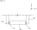
- FIG. 4 is a cross-sectional view illustrating a state in which the gripper part 510 is gripping the jig part 100.
- FIG. 5 is a perspective view illustrating a supply battery storage unit 300.
- FIG. 6 is a perspective view illustrating a recovery battery storage unit 400.
- FIG. 7 is a perspective view illustrating a gas diffusion chamber 200.
- the z-axis direction may be a vertical direction
- the x-axis direction may be a first direction
- the y-axis direction may be a second direction.
- the gas analysis apparatus of the present disclosure is for analyzing gas generated inside a secondary battery, and may be capable of loading a battery to be analyzed 11 into a closed space, diffusing the gas generated from the battery to be analyzed 11 into the closed space, collecting the diffused gas, delivering the collected gas to a gas analysis unit to perform gas analysis, and unloading the battery to be analyzed 11 after the analysis from the closed space, without manual work by the analyst.
- the gas analysis apparatus of the present disclosure may ensure the safety of the analyst and minimize human errors caused by manipulation of the analyst during the gas collection and analysis process.
- the gas analysis apparatus of the present disclosure may include:
- the gas analysis unit may be equipment capable of quantitative and qualitative analysis of gas using gas chromatography (GC) analysis equipment, and the like.
- the gas analysis unit may be gas chromatography/mass spectrometer (GC/MS) analysis equipment.
- the battery to be analyzed 11 may not be accommodated alone in the gas diffusion space provided inside the gas diffusion chamber 200, but may be mounted on the jig part 100 made of Teflon material the like, and then accommodated in the gas diffusion space.
- the process of mounting the battery to be analyzed 11 on the jig part 100 may be performed manually by the analyst, and subsequent processes may be performed automatically without any intervention of the analyst.
- the process of loading the jig part 100 into the gas diffusion chamber 200, the process of diffusing gas into the gas diffusion space of the gas diffusion chamber 200, the process of delivering the diffused gas to the gas analysis unit, and the process of unloading the jig part 100 from the gas diffusion chamber 200 may be performed automatically without direct manipulation by the analyst.
- the jig part 100 may be made of Teflon material, a chemicalresistant material, as described above, and a battery accommodation groove 110 for mounting the battery to be analyzed 11 may be formed on an upper surface of the jig part 100.
- the jig part 100 may be formed in a rectangular parallelepiped shape.
- the gas analysis apparatus of the present disclosure may be capable of sequentially analyzing a plurality of batteries to be analyzed 11.
- a plurality of jig parts 100 may also be provided in order to correspond to the number of the plurality of batteries to be analyzed 11.
- Each of the plurality of batteries to be analyzed 11 may be mounted on each of the plurality of jig parts 100. At this time, the plurality of batteries to be analyzed 11 may each be provided in different volumes or shapes.
- the plurality of jig parts 100 are all provided to have the same outer shape and specifications, but the size of the battery accommodation groove 110 is provided to correspond to the specifications of each of the batteries to be analyzed 11 which is mounted thereto, so that when the jig part 100 is accommodated in the gas diffusion space, a difference in volume of the space where the gas substantially diffuses may be made similar for each battery to be analyzed 11.
- a gas discharge groove 130 may be formed on the upper surface of the jig part 100 so that the gas of the battery accommodation groove 110 may easily diffuse into the gas diffusion space.
- One end of the gas discharge groove 130 may be connected to the battery accommodation groove 110, and the other end may be located at the edge of the jig part 100. Accordingly, the gas of the battery accommodation groove 110 may escape from the side surface of the jig part 100 through the gas discharge groove 130 and diffuse into the gas diffusion space.
- the battery moving unit 500 may include a gripper part 510 for gripping the jig part 100, an elevation driving part 520 for linearly moving the gripper part 510 in a vertical direction, and a first driving part 530 for moving the gripper part 510 in a first direction perpendicular to the vertical direction.
- the gripper part 510 may include a pair of grip members 511 configured to grip the jig part 100 by contacting each of both side surfaces of the jig part 100 formed as a plane perpendicular to the second direction.
- the pair of grip members 511 face each other, and the surfaces facing each other are formed as planes, so that they may grip the jig part 100 by being in close contact with both side surfaces of the jig part 100.
- a pair of gripper insertion groove 120 parts may be formed in the jig part 100, and each of the pair of gripper insertion groove 120 parts may be located on each of the both side surfaces of the jig part 100 formed as a plane perpendicular to the second direction.
- the gripper insertion groove 120 part may be formed at a location facing the grip member 511 when gripping the jig part 100 of the gripper part 510.
- Each of the pair of gripper insertion groove 120 parts may include a first gripper insertion groove 121 formed in a long groove shape, and a second gripper insertion groove 122 formed to be spaced a predetermined distance apart from the first gripper insertion groove 121, respectively.
- the first gripper insertion groove 121 may be provided in the shape of a long groove extending in the first direction.
- the second gripper insertion groove 122 may be formed on both side locations of the first gripper insertion groove 121 to be spaced a predetermined distance apart in the first direction. Therefore, two second gripper insertion grooves 122 may be allocated to each first gripper insertion groove 121.
- one jig part 100 may be provided with two first gripper insertion grooves 121 and four second gripper insertion grooves 122.
- a first protrusion 511a to be inserted into the first gripper insertion groove 121 and a second protrusion 511b to be inserted into the second gripper insertion groove 122 may be formed on the pair of grip members 511.
- the first protrusion 511a may be provided in a shape extending in the first direction to correspond to the shape of the first gripper insertion groove 121
- the second protrusion 511b may also be provided in a shape corresponding to the shape of the second gripper insertion groove 122.
- One first protrusion 511a and two second protrusions 511b may be formed on one grip member 511.
- the jig part 100 is made of a material with low friction such as Teflon, when gripping the jig part 100 by the gripper part 510, the first protrusion 511a is inserted into the first gripper insertion groove 121, and the second protrusion 511b is inserted into the second gripper insertion groove 122, so that the jig part 100 may be stably gripped without shaking.
- the gripper part 510 may further include a grip actuator 512 configured to provide driving force to adjust a gap between the pair of grip members 511, and a gripper body member 513 to which the grip actuator 512 and the pair of grip members 511 are coupled.
- the grip actuator 512 may be an electric or pneumatic actuator.
- the pair of grip members 511 may be fixed to the gripper body member 513 so that they are capable of sliding in the second direction.
- the first driving part 530 may include a first moving member 531 configured to move linearly in the first direction, and a first guide member 532 configured to guide a movement of the first moving member 531
- the elevation driving part 520 may include an elevation guide member 522 coupled to the first moving member 531, and an elevation moving member 521 configured to move linearly in the vertical direction along the elevation guide member 522, wherein the gripper body member 513 may be fixed to the elevation moving member 521.
- the supply battery storage unit 300 may include a supply battery storage part 310 provided with the supply battery storage space inside and extending in the vertical direction, and a supply battery lifting part 320 configured to lift up the jig part 100 in the supply battery storage space, wherein a battery discharge port 311 may be formed at an upper end of the supply battery storage part 310, and a first gripper contact hole 312 may be formed on each of both side surfaces of the supply battery storage part 310 so that the pair of grip members 511 can directly contact each of the both side surfaces of the jig part 100 formed as a plane perpendicular to the second direction.
- the supply battery storage part 310 may be provided in the shape of a square pillar extending in the vertical direction.
- the plurality of jig parts 100 may be stacked in the vertical direction and loaded.
- the supply battery lifting part 320 may support the bottom surface of the lowest jig part 100 among the plurality of jig parts 100 stacked in the vertical direction.
- the gripper part 510 takes out one jig part 100 from the supply battery storage space through the battery discharge port 311, the supply battery lifting part 320 rises, and may lift up the height of the uppermost jig part 100 among the plurality of jig parts 100 located in the supply battery storage space to an appropriate location for the gripper part 510 to grip.
- the first gripper contact holes 312 may be provided in pairs, and each of the pair of first gripper contact holes 312 may be formed in a shape that penetrates each of two planes perpendicular to the second direction of the supply battery storage part 310.
- the pair of first gripper contact holes 312 may be provided in a shape extending in the vertical direction, and the upper ends of the pair of first gripper contact holes 312 may be connected to the battery discharge port 311.
- the recovery battery storage unit 400 may include a recovery battery storage part 410 provided with the recovery battery storage space inside and extending in the vertical direction, and a recovery battery lowering part 420 configured to lower the jig part 100 in the recovery battery storage space, wherein a battery recovery port 411 may be formed at an upper end of the recovery battery storage part 410, and a second gripper contact hole 412 may be formed on each of both side surfaces of the recovery battery storage part 410 so that the pair of grip members 511 can directly contact each of the both side surfaces of the jig part 100 formed as a plane perpendicular to the second direction.
- the recovery battery storage part 410 may be provided in the shape of a square pillar extending in the vertical direction. In the recovery battery storage space inside the recovery battery storage part 410, the plurality of jig parts 100 recovered from the gas diffusion chamber 200 may be stacked in the vertical direction and loaded.
- the recovery battery lowering part 420 may support the bottom surface of the lowest jig part 100 among the plurality of jig parts 100 stacked in the vertical direction.
- the recovery battery lowering part 420 descends, and may lower the height of the uppermost jig part 100 among the plurality of jig parts 100 located in the recovery battery storage space to an appropriate location for the gripper part 510 to place.
- the second gripper contact holes 412 may be provided in pairs, and each of the pair of second gripper contact holes 412 may be formed in a shape that penetrates each of two planes perpendicular to the second direction of the recovery battery storage part 410.
- the pair of second gripper contact holes 412 may be provided in a shape extending in the vertical direction, and the upper end of the pair of second gripper contact holes 412 may be connected to the battery recovery port 411.
- the gas diffusion chamber 200 may be located to be spaced a predetermined distance apart from the supply battery storage unit 300 and the recovery battery storage unit 400 in the first direction.
- the gripper part 510 may move between the gas diffusion chamber 200 and the supply battery storage unit 300 or between the gas diffusion chamber 200 and the recovery battery storage unit 400 by the first driving part 530.
- the gas diffusion chamber 200 may include a chamber body part 210, wherein a jig part accommodation groove 211 is formed on an upper surface of the chamber body part 210 as the gas diffusion space, and a chamber cover part 220 configured to cover an upper surface of the chamber body part 210 to make the gas diffusion space a closed space, and the chamber cover part 220 may be configured to open or close the gas diffusion space by sliding in a second direction perpendicular to the vertical direction and the first direction.
- a sealing member insertion groove 212 may be formed on the upper surface of the chamber body part 210 around the jig part accommodation groove 211.
- the sealing member insertion groove 212 may be provided in a closed loop shape so that a sealing member such as an O-ring may be inserted, and the jig part accommodation groove 211 may be located inside the inner circumference of the sealing member insertion groove 212.
- the upper surface of the chamber body part 210 and the bottom surface of the chamber cover part may be formed as planes to be completely adhered to each other.
- the battery moving unit may further include a second driving part (not shown) to locate the center of the gripper body member 513 of the gripper part 510 together with one of the center of the jig part accommodation groove 211, the center of the discharge port 311 of the supply battery storage part 310 and the center of the recovery port 411 of the recovery battery storage part 410 together on an imaginary plane parallel to the first direction and the vertical direction.
- a second driving part (not shown) to locate the center of the gripper body member 513 of the gripper part 510 together with one of the center of the jig part accommodation groove 211, the center of the discharge port 311 of the supply battery storage part 310 and the center of the recovery port 411 of the recovery battery storage part 410 together on an imaginary plane parallel to the first direction and the vertical direction.
- the second driving part may cause the center of the gripper body member 513 of the gripper part 510 to be in the same position as one of the center of the jig part accommodation groove 211, the center of the discharge port 311 of the supply battery storage part 310 and the center of the recovery port 411 of the recovery battery storage part 410 in the second direction.
- the second driving part may be mounted on the first moving member 531 or the elevation moving member 521.
- the center of the discharge port 311 of the supply battery storage part 310, the center of the recovery port 411 of the recovery battery storage part 410, and the center of the jig part accommodation groove 211 may be located on an imaginary plane parallel to the first direction and the vertical direction.
- the center of the discharge port 311 of the supply battery storage part 310, the center of the recovery port 411 of the recovery battery storage part 410, and the center of the jig part accommodation groove 211 may be located at the same position in the second direction. Accordingly, the distance between the supply battery storage unit 300 and the gas diffusion chamber 200 may be formed to be farther or closer than the distance between the recovery battery storage unit 400 and the gas diffusion chamber 200.
- the second driving part may be omitted.
- a punching part 221 for perforating the battery to be analyzed 11 may be provided on an upper surface of the chamber cover part 220, wherein a punching needle of the punching part 221 may be configured to perforate the battery to be analyzed 11 by being inserted into the gas diffusion space through a penetration hole of the chamber cover part 220.
- the punching part 221 may move the punching needle in the vertical direction through an electric motor or actuator.
- the gas delivery flow path 290 may be connected to the chamber body part 210.
- the gas delivery flow path 290 may include a tube, hose, pipe, etc., through which gas may move.
- a manifold may be provided in the gas delivery flow path 290, and the gas delivered from the gas diffusion space to the gas analysis unit through the gas delivery flow path 290 may be injected into the gas analysis unit after waiting in the manifold for a predetermined period of time.
- a gas collection container for storing the gas diffused in the gas diffusion space, a dilution chamber for diluting the gas stored in the gas collection container, and a vacuum pump may be connected to the manifold.
- a gas analysis apparatus of the present disclosure is an automated system which may be capable of collecting and analyzing secondary battery generated gas by minimizing the intervention of the analyst.
- the gas analysis apparatus of the present disclosure may be capable of independently collecting and analyzing gases for a plurality of secondary batteries with only the initial settings of the analyst.
- the gas analysis apparatus of the present disclosure may be capable of continuous analysis even if the analyst is not waiting near the gas analysis apparatus.
Landscapes
- Chemical & Material Sciences (AREA)
- Health & Medical Sciences (AREA)
- Life Sciences & Earth Sciences (AREA)
- Engineering & Computer Science (AREA)
- General Physics & Mathematics (AREA)
- Pathology (AREA)
- Immunology (AREA)
- Physics & Mathematics (AREA)
- Analytical Chemistry (AREA)
- Biochemistry (AREA)
- General Health & Medical Sciences (AREA)
- Food Science & Technology (AREA)
- Medicinal Chemistry (AREA)
- Combustion & Propulsion (AREA)
- Robotics (AREA)
- Manufacturing & Machinery (AREA)
- Chemical Kinetics & Catalysis (AREA)
- Electrochemistry (AREA)
- General Chemical & Material Sciences (AREA)
- Sampling And Sample Adjustment (AREA)
- Secondary Cells (AREA)
Abstract
Description
- The present application claims the benefit of priority based on
Korean Patent Application No. 10-2022-0178983 filed on December 20, 2022 - The present disclosure relates to a gas analysis apparatus, and to a gas analysis apparatus capable of individually collecting and analyzing gases generated from each of a plurality of batteries to be analyzed using an automated system.
- In general, a secondary battery is a battery which can be used repeatedly through a discharging process in which chemical energy is converted into electrical energy and a charging process in the opposite direction to the discharging process and which includes nickelcadmium (Ni-Cd) batteries, nickel-metal hydride (Ni-MH) batteries, lithium-metal batteries, lithium-ion (Li-ion) batteries, and lithium-ion polymer batteries. Among these secondary batteries, lithium secondary batteries having high energy density and voltage, long cycle life, and a low self-discharge rate have been commercialized and widely used.
- Depending on the reaction within the lithium secondary battery, various types of gases such as hydrogen, oxygen, nitrogen, carbon monoxide, carbon dioxide, hydrocarbons of CnH2n-2 (n=2~5), CnH2n (n=2~5), and CnH2n+2 (n=1~5), and other organic gas species, may be generated as secondary battery generated gas.
- In addition, the lithium secondary battery degrades while generating a large amount of secondary battery generated gas due to electrolyte decomposition as repeated charging and discharging progresses, and this aspect appears differently depending on the design and use form of the battery. Thus, it is essential to infer a deterioration mechanism of a battery by analyzing the secondary battery generated gas during a battery development process.
- Therefore, it is very important to accurately analyze the secondary battery generated gas. Specifically, information on composition and content of the secondary battery generated gas is useful for developing battery materials, optimizing battery manufacturing processes, and identifying causes of battery defects. To this end, it is important to develop a technology to analyze the secondary battery generated gas.
- Analysis of the secondary battery generated gas may be performed by steps of collecting gas generated inside the secondary battery, delivering the collected gas to an analysis apparatus such as a gas chromatography (GC) for GC measurement, and analyzing measurement data. Since the composition and amount of the secondary battery generated gas varies depending on not only the type of secondary battery, but also the conditions given to the secondary battery such as cycle number, SOC, and temperature, individual analysis is necessary for various types of secondary batteries, and individual collection and analysis of secondary battery generated gas is necessary for each of the various conditions. In other words, analysis of secondary battery generated gas may be repeatedly performed on a plurality of secondary batteries.
- This repetitive work increases fatigue of an analyst as the number of samples increases, and human error may also occur depending on the skill level of the analyst. In addition, secondary battery analysis may be performed for a long time, and in this case, there were limitations to the analysis method performed by manual operations of the analyst.
- Therefore, there is a need for automated analysis technology capable of automating gas collection in secondary batteries and GC measurement operations of the collected gas to minimize human errors, and enable efficient and accurate analysis.
- Technical Goals
- The present disclosure relates to a gas analysis apparatus, and is to provide a gas analysis apparatus capable of individually collecting and analyzing gases generated from each of a plurality of batteries to be analyzed using an automated system.
- Technical objects to be achieved by the present disclosure are not limited to the technical objects mentioned above, and other technical objects not mentioned will be clearly understood by those skilled in the art from the description below.
- A gas analysis apparatus of the present disclosure may include:
- a jig part on which a battery to be analyzed is mounted;
- a gas diffusion chamber provided with a gas diffusion space in which the jig part is accommodated inside;
- a supply battery storage unit provided with a supply battery storage space in which the jig part for supplying to the gas diffusion space is stored;
- a recovery battery storage unit provided with a recovery battery storage space in which the jig part recovered from the gas diffusion space is stored;
- a battery moving unit configured to move the jig part from the battery supply part to the gas diffusion space or move the jig part accommodated in the gas diffusion space to the battery recovery part;
- a gas analysis unit configured to analyze gas delivered from the gas diffusion space; and
- a gas delivery flow path configured to connect the gas diffusion space and the gas analysis unit.
- A gas analysis apparatus of the present disclosure is an automated system which may be capable of collecting and analyzing secondary battery generated gas by minimizing intervention of the analyst.
- The gas analysis apparatus of the present disclosure may be capable of independently collecting and analyzing gases for a plurality of secondary batteries with only initial settings of the analyst.
- The gas analysis apparatus of the present disclosure may be capable of continuous analysis even if the analyst is not waiting near the gas analysis apparatus.
-
-
FIG. 1 is a perspective view illustrating a gas analysis apparatus of the present disclosure. -
FIG. 2 is a perspective view illustrating a jig part. -
FIG. 3 is a perspective view illustrating a gripper part. -
FIG. 4 is a cross-sectional view illustrating a state in which the gripper part is gripping the jig part. -
FIG. 5 is a perspective view illustrating a supply battery storage unit. -
FIG. 6 is a perspective view illustrating a recovery battery storage unit. -
FIG. 7 is a perspective view illustrating a gas diffusion chamber. - A gas analysis apparatus of the present disclosure may include:
- a jig part on which a battery to be analyzed is mounted;
- a gas diffusion chamber provided with a gas diffusion space in which the jig part is accommodated inside;
- a supply battery storage unit provided with a supply battery storage space in which the jig part for supplying to the gas diffusion space is stored;
- a recovery battery storage unit provided with a recovery battery storage space in which the jig part recovered from the gas diffusion space is stored;
- a battery moving unit configured to move the jig part from the battery supply part to the gas diffusion space or move the jig part accommodated in the gas diffusion space to the battery recovery part;
- a gas analysis unit configured to analyze gas delivered from the gas diffusion space; and
- a gas delivery flow path configured to connect the gas diffusion space and the gas analysis unit.
- In the gas analysis apparatus of the present disclosure, a battery accommodation groove for mounting the battery to be analyzed may be formed on an upper surface of the jig part.
- In the gas analysis apparatus of the present disclosure, the battery moving unit may include a gripper part for gripping the jig part, an elevation driving part for linearly moving the gripper part in a vertical direction, and a first driving part for moving the gripper part in a first direction perpendicular to the vertical direction.
- In the gas analysis apparatus of the present disclosure, when a direction perpendicular to the vertical direction and the first direction is referred to as a second direction, the gripper part may include a pair of grip members configured to grip the jig part by contacting each of both side surfaces of the jig part formed as a plane perpendicular to the second direction.
- In the gas analysis apparatus of the present disclosure, a pair of gripper insertion groove parts may be formed in the jig part, and each of the pair of gripper insertion groove parts may be located on each of the both side surfaces of the jig part formed as the plane perpendicular to the second direction.
- In the gas analysis apparatus of the present disclosure, each of the pair of gripper insertion groove parts may include a first gripper insertion groove formed in a long groove shape, and a second gripper insertion groove formed to be spaced a predetermined distance apart from the first gripper insertion groove.
- In the gas analysis apparatus of the present disclosure, a first protrusion to be inserted into the first gripper insertion groove and a second protrusion to be inserted into the second gripper insertion groove may be formed on the pair of grip members.
- In the gas analysis apparatus of the present disclosure, the gripper part may further include a grip actuator configured to provide driving force to adjust a gap between the pair of grip members, and a gripper body member to which the grip actuator and the pair of grip members are coupled, the first driving part may include a first moving member configured to move linearly in the first direction, and a first guide member configured to guide a movement of the first moving member, the elevation driving part may include an elevation guide member coupled to the first moving member, and an elevation moving member configured to move linearly in the vertical direction along the elevation guide member, and the gripper body member may be fixed to the elevation moving member.
- In the gas analysis apparatus of the present disclosure, the supply battery storage unit may include a supply battery storage part provided with the supply battery storage space inside and extending in the vertical direction, and a supply battery lifting part configured to lift up the jig part in the supply battery storage space, a battery discharge port may be formed at an upper end of the supply battery storage part, and a first gripper contact hole may be formed on each of both side surfaces of the supply battery storage part so that the pair of grip members can directly contact each of the both side surfaces of the jig part formed as the plane perpendicular to the second direction.
- In the gas analysis apparatus of the present disclosure, the recovery battery storage unit may include a recovery battery storage part provided with the recovery battery storage space inside and extending in the vertical direction, and a recovery battery lowering part configured to lower the jig part in the recovery battery storage space, a battery recovery port may be formed at an upper end of the recovery battery storage part, and a second gripper contact hole may be formed on each of both side surfaces of the recovery battery storage part so that the pair of grip members can directly contact each of the both side surfaces of the jig part formed as the plane perpendicular to the second direction.
- In the gas analysis apparatus of the present disclosure, the gas diffusion chamber may be located to be spaced a predetermined distance apart from the supply battery storage unit and the recovery battery storage unit in the first direction, the gas diffusion chamber may include a chamber body part, wherein a jig part accommodation groove is formed on an upper surface of the chamber body part as the gas diffusion space, and a chamber cover part configured to cover the upper surface of the chamber body part to make the gas diffusion space a closed space, and the chamber cover part may be configured to open or close the gas diffusion space by sliding in a second direction perpendicular to the vertical direction and the first direction.
- In the gas analysis apparatus of the present disclosure, a punching part for perforating the battery to be analyzed may be provided on an upper surface of the chamber cover part, and a punching needle of the punching part may be configured to perforate the battery to be analyzed by being inserted into the gas diffusion space through a penetration hole of the chamber cover part.
- In the gas analysis apparatus of the present disclosure, the gas delivery flow path may be connected to the chamber body part.
- In the gas analysis apparatus of the present disclosure, a manifold may be provided in the gas delivery flow path, and the gas delivered from the gas diffusion space to the gas analysis unit through the gas delivery flow path may be injected into the gas analysis unit after waiting in the manifold for a predetermined period of time.
- Hereinafter, embodiments according to the present disclosure will be described in detail with reference to the accompanying drawings. In this process, the size or shape of the components shown in the drawings may be exaggerated for clarity and convenience of explanation. In addition, terms specifically defined in consideration of the configuration and operation of the present disclosure may vary according to the intentions or customs of users and operators. Definitions of these terms should be made based on the content throughout this specification.
- In the description of the present disclosure, it should be noted that an orientation or positional relationship indicated by the terms such as "center", "upper", "lower", "left", "right", "vertical", "horizontal", "inner side", "outer side", "one side", and "other side" is based on an orientation or positional relationship shown in a drawing or an orientation or positional relationship that is placed when using the product of the present disclosure on a daily basis, and is merely for explanation and brief description of the present disclosure, and it does not suggest or imply that the displayed device or element must necessarily be configured or operated in a specified orientation and should not be construed as limiting the present disclosure.
-
FIG. 1 is a perspective view illustrating a gas analysis apparatus of the present disclosure.FIG. 2 is a perspective view illustrating ajig part 100.FIG. 3 is a perspective view illustrating agripper part 510.FIG. 4 is a cross-sectional view illustrating a state in which thegripper part 510 is gripping thejig part 100.FIG. 5 is a perspective view illustrating a supplybattery storage unit 300.FIG. 6 is a perspective view illustrating a recoverybattery storage unit 400.FIG. 7 is a perspective view illustrating agas diffusion chamber 200. - Hereinafter, the gas analysis apparatus of the present disclosure will be described in detail with reference to
FIGS. 1 to 7 . - Hereinafter, in the coordinate system shown in
FIGS. 1 to 7 , the z-axis direction may be a vertical direction, the x-axis direction may be a first direction, and the y-axis direction may be a second direction. - The gas analysis apparatus of the present disclosure is for analyzing gas generated inside a secondary battery, and may be capable of loading a battery to be analyzed 11 into a closed space, diffusing the gas generated from the battery to be analyzed 11 into the closed space, collecting the diffused gas, delivering the collected gas to a gas analysis unit to perform gas analysis, and unloading the battery to be analyzed 11 after the analysis from the closed space, without manual work by the analyst.
- Therefore, the gas analysis apparatus of the present disclosure may ensure the safety of the analyst and minimize human errors caused by manipulation of the analyst during the gas collection and analysis process.
- As shown in
FIG. 1 , the gas analysis apparatus of the present disclosure may include: - the
jig part 100 on which the battery to be analyzed 11 is mounted; - the
gas diffusion chamber 200 provided with a gas diffusion space in which thejig part 100 is accommodated inside; - the supply
battery storage unit 300 provided with a supply battery storage space in which thejig part 100 for supplying to the gas diffusion space is stored; - the recovery
battery storage unit 400 provided with a recovery battery storage space in which thejig part 100 recovered from the gas diffusion space is stored; - a
battery moving unit 500 configured to move thejig part 100 from the battery supply part to the gas diffusion space or move thejig part 100 accommodated in the gas diffusion space to the battery recovery part; - a gas analysis unit configured to analyze gas delivered from the gas diffusion space; and
- a gas
delivery flow path 290 configured to connect the gas diffusion space and the gas analysis unit. - The gas analysis unit may be equipment capable of quantitative and qualitative analysis of gas using gas chromatography (GC) analysis equipment, and the like. For example, the gas analysis unit may be gas chromatography/mass spectrometer (GC/MS) analysis equipment.
- In the gas analysis apparatus of the present disclosure, the battery to be analyzed 11 may not be accommodated alone in the gas diffusion space provided inside the
gas diffusion chamber 200, but may be mounted on thejig part 100 made of Teflon material the like, and then accommodated in the gas diffusion space. - In the gas analysis apparatus of the present disclosure, up to the process of mounting the battery to be analyzed 11 on the
jig part 100 may be performed manually by the analyst, and subsequent processes may be performed automatically without any intervention of the analyst. Specifically, the process of loading thejig part 100 into thegas diffusion chamber 200, the process of diffusing gas into the gas diffusion space of thegas diffusion chamber 200, the process of delivering the diffused gas to the gas analysis unit, and the process of unloading thejig part 100 from thegas diffusion chamber 200 may be performed automatically without direct manipulation by the analyst. - As shown in
FIG. 2 , thejig part 100 may be made of Teflon material, a chemicalresistant material, as described above, and abattery accommodation groove 110 for mounting the battery to be analyzed 11 may be formed on an upper surface of thejig part 100. For example, thejig part 100 may be formed in a rectangular parallelepiped shape. - The gas analysis apparatus of the present disclosure may be capable of sequentially analyzing a plurality of batteries to be analyzed 11. A plurality of
jig parts 100 may also be provided in order to correspond to the number of the plurality of batteries to be analyzed 11. Each of the plurality of batteries to be analyzed 11 may be mounted on each of the plurality ofjig parts 100. At this time, the plurality of batteries to be analyzed 11 may may each be provided in different volumes or shapes. The plurality ofjig parts 100 are all provided to have the same outer shape and specifications, but the size of thebattery accommodation groove 110 is provided to correspond to the specifications of each of the batteries to be analyzed 11 which is mounted thereto, so that when thejig part 100 is accommodated in the gas diffusion space, a difference in volume of the space where the gas substantially diffuses may be made similar for each battery to be analyzed 11. - A
gas discharge groove 130 may be formed on the upper surface of thejig part 100 so that the gas of thebattery accommodation groove 110 may easily diffuse into the gas diffusion space. One end of thegas discharge groove 130 may be connected to thebattery accommodation groove 110, and the other end may be located at the edge of thejig part 100. Accordingly, the gas of thebattery accommodation groove 110 may escape from the side surface of thejig part 100 through thegas discharge groove 130 and diffuse into the gas diffusion space. - As shown in
FIG. 3 , thebattery moving unit 500 may include agripper part 510 for gripping thejig part 100, anelevation driving part 520 for linearly moving thegripper part 510 in a vertical direction, and afirst driving part 530 for moving thegripper part 510 in a first direction perpendicular to the vertical direction. - When a direction perpendicular to the vertical direction and the first direction is referred to as a second direction, the
gripper part 510 may include a pair ofgrip members 511 configured to grip thejig part 100 by contacting each of both side surfaces of thejig part 100 formed as a plane perpendicular to the second direction. - The pair of
grip members 511 face each other, and the surfaces facing each other are formed as planes, so that they may grip thejig part 100 by being in close contact with both side surfaces of thejig part 100. - As shown in
FIG. 4 , a pair ofgripper insertion groove 120 parts may be formed in thejig part 100, and each of the pair ofgripper insertion groove 120 parts may be located on each of the both side surfaces of thejig part 100 formed as a plane perpendicular to the second direction. Thegripper insertion groove 120 part may be formed at a location facing thegrip member 511 when gripping thejig part 100 of thegripper part 510. - Each of the pair of
gripper insertion groove 120 parts may include a firstgripper insertion groove 121 formed in a long groove shape, and a secondgripper insertion groove 122 formed to be spaced a predetermined distance apart from the firstgripper insertion groove 121, respectively. Specifically, the firstgripper insertion groove 121 may be provided in the shape of a long groove extending in the first direction. The secondgripper insertion groove 122 may be formed on both side locations of the firstgripper insertion groove 121 to be spaced a predetermined distance apart in the first direction. Therefore, two secondgripper insertion grooves 122 may be allocated to each firstgripper insertion groove 121. In other words, onejig part 100 may be provided with two firstgripper insertion grooves 121 and four secondgripper insertion grooves 122. - A
first protrusion 511a to be inserted into the firstgripper insertion groove 121 and asecond protrusion 511b to be inserted into the secondgripper insertion groove 122 may be formed on the pair ofgrip members 511. Specifically, thefirst protrusion 511a may be provided in a shape extending in the first direction to correspond to the shape of the firstgripper insertion groove 121, and thesecond protrusion 511b may also be provided in a shape corresponding to the shape of the secondgripper insertion groove 122. Onefirst protrusion 511a and twosecond protrusions 511b may be formed on onegrip member 511. As described above, since thejig part 100 is made of a material with low friction such as Teflon, when gripping thejig part 100 by thegripper part 510, thefirst protrusion 511a is inserted into the firstgripper insertion groove 121, and thesecond protrusion 511b is inserted into the secondgripper insertion groove 122, so that thejig part 100 may be stably gripped without shaking. - The
gripper part 510 may further include agrip actuator 512 configured to provide driving force to adjust a gap between the pair ofgrip members 511, and agripper body member 513 to which thegrip actuator 512 and the pair ofgrip members 511 are coupled. - The
grip actuator 512 may be an electric or pneumatic actuator. - The pair of
grip members 511 may be fixed to thegripper body member 513 so that they are capable of sliding in the second direction. - The
first driving part 530 may include a first movingmember 531 configured to move linearly in the first direction, and afirst guide member 532 configured to guide a movement of the first movingmember 531, and theelevation driving part 520 may include an elevation guide member 522 coupled to the first movingmember 531, and anelevation moving member 521 configured to move linearly in the vertical direction along the elevation guide member 522, wherein thegripper body member 513 may be fixed to theelevation moving member 521. - As shown in
FIG. 5 , the supplybattery storage unit 300 may include a supplybattery storage part 310 provided with the supply battery storage space inside and extending in the vertical direction, and a supplybattery lifting part 320 configured to lift up thejig part 100 in the supply battery storage space, wherein abattery discharge port 311 may be formed at an upper end of the supplybattery storage part 310, and a firstgripper contact hole 312 may be formed on each of both side surfaces of the supplybattery storage part 310 so that the pair ofgrip members 511 can directly contact each of the both side surfaces of thejig part 100 formed as a plane perpendicular to the second direction. - The supply
battery storage part 310 may be provided in the shape of a square pillar extending in the vertical direction. In the supply battery storage space inside the supplybattery storage part 310, the plurality ofjig parts 100 may be stacked in the vertical direction and loaded. The supplybattery lifting part 320 may support the bottom surface of thelowest jig part 100 among the plurality ofjig parts 100 stacked in the vertical direction. When thegripper part 510 takes out onejig part 100 from the supply battery storage space through thebattery discharge port 311, the supplybattery lifting part 320 rises, and may lift up the height of theuppermost jig part 100 among the plurality ofjig parts 100 located in the supply battery storage space to an appropriate location for thegripper part 510 to grip. - The first gripper contact holes 312 may be provided in pairs, and each of the pair of first gripper contact holes 312 may be formed in a shape that penetrates each of two planes perpendicular to the second direction of the supply
battery storage part 310. The pair of first gripper contact holes 312 may be provided in a shape extending in the vertical direction, and the upper ends of the pair of first gripper contact holes 312 may be connected to thebattery discharge port 311. - As shown in
FIG. 6 , the recoverybattery storage unit 400 may include a recoverybattery storage part 410 provided with the recovery battery storage space inside and extending in the vertical direction, and a recoverybattery lowering part 420 configured to lower thejig part 100 in the recovery battery storage space, wherein abattery recovery port 411 may be formed at an upper end of the recoverybattery storage part 410, and a secondgripper contact hole 412 may be formed on each of both side surfaces of the recoverybattery storage part 410 so that the pair ofgrip members 511 can directly contact each of the both side surfaces of thejig part 100 formed as a plane perpendicular to the second direction. - The recovery
battery storage part 410 may be provided in the shape of a square pillar extending in the vertical direction. In the recovery battery storage space inside the recoverybattery storage part 410, the plurality ofjig parts 100 recovered from thegas diffusion chamber 200 may be stacked in the vertical direction and loaded. The recoverybattery lowering part 420 may support the bottom surface of thelowest jig part 100 among the plurality ofjig parts 100 stacked in the vertical direction. When thegripper part 510 loads thejig part 100 in the recovery battery storage space through thebattery recovery port 411, the recoverybattery lowering part 420 descends, and may lower the height of theuppermost jig part 100 among the plurality ofjig parts 100 located in the recovery battery storage space to an appropriate location for thegripper part 510 to place. - The second gripper contact holes 412 may be provided in pairs, and each of the pair of second gripper contact holes 412 may be formed in a shape that penetrates each of two planes perpendicular to the second direction of the recovery
battery storage part 410. The pair of second gripper contact holes 412 may be provided in a shape extending in the vertical direction, and the upper end of the pair of second gripper contact holes 412 may be connected to thebattery recovery port 411. - The
gas diffusion chamber 200 may be located to be spaced a predetermined distance apart from the supplybattery storage unit 300 and the recoverybattery storage unit 400 in the first direction. Thegripper part 510 may move between thegas diffusion chamber 200 and the supplybattery storage unit 300 or between thegas diffusion chamber 200 and the recoverybattery storage unit 400 by thefirst driving part 530. - As shown in
FIG. 7 , thegas diffusion chamber 200 may include achamber body part 210, wherein a jigpart accommodation groove 211 is formed on an upper surface of thechamber body part 210 as the gas diffusion space, and achamber cover part 220 configured to cover an upper surface of thechamber body part 210 to make the gas diffusion space a closed space, and thechamber cover part 220 may be configured to open or close the gas diffusion space by sliding in a second direction perpendicular to the vertical direction and the first direction. - A sealing
member insertion groove 212 may be formed on the upper surface of thechamber body part 210 around the jigpart accommodation groove 211. Specifically, the sealingmember insertion groove 212 may be provided in a closed loop shape so that a sealing member such as an O-ring may be inserted, and the jigpart accommodation groove 211 may be located inside the inner circumference of the sealingmember insertion groove 212. - The upper surface of the
chamber body part 210 and the bottom surface of the chamber cover part may be formed as planes to be completely adhered to each other. - In one embodiment, the battery moving unit may further include a second driving part (not shown) to locate the center of the
gripper body member 513 of thegripper part 510 together with one of the center of the jigpart accommodation groove 211, the center of thedischarge port 311 of the supplybattery storage part 310 and the center of therecovery port 411 of the recoverybattery storage part 410 together on an imaginary plane parallel to the first direction and the vertical direction. In other words, the second driving part may cause the center of thegripper body member 513 of thegripper part 510 to be in the same position as one of the center of the jigpart accommodation groove 211, the center of thedischarge port 311 of the supplybattery storage part 310 and the center of therecovery port 411 of the recoverybattery storage part 410 in the second direction. The second driving part may be mounted on the first movingmember 531 or theelevation moving member 521. - In another embodiment, the center of the
discharge port 311 of the supplybattery storage part 310, the center of therecovery port 411 of the recoverybattery storage part 410, and the center of the jigpart accommodation groove 211 may be located on an imaginary plane parallel to the first direction and the vertical direction. In other words, the center of thedischarge port 311 of the supplybattery storage part 310, the center of therecovery port 411 of the recoverybattery storage part 410, and the center of the jigpart accommodation groove 211 may be located at the same position in the second direction. Accordingly, the distance between the supplybattery storage unit 300 and thegas diffusion chamber 200 may be formed to be farther or closer than the distance between the recoverybattery storage unit 400 and thegas diffusion chamber 200. In other words, on an imaginary straight line parallel to the first direction, they may be arranged in the order of [gas diffusion chamber 200] - [supply battery storage unit 300] - [recovery battery storage unit 400] or arranged in the order of [gas diffusion chamber 200] - [recovery battery storage unit 400] - [supply battery storage unit 300]. In this case, the second driving part may be omitted. - A punching
part 221 for perforating the battery to be analyzed 11 may be provided on an upper surface of thechamber cover part 220, wherein a punching needle of the punchingpart 221 may be configured to perforate the battery to be analyzed 11 by being inserted into the gas diffusion space through a penetration hole of thechamber cover part 220. - The punching
part 221 may move the punching needle in the vertical direction through an electric motor or actuator. - The gas
delivery flow path 290 may be connected to thechamber body part 210. The gasdelivery flow path 290 may include a tube, hose, pipe, etc., through which gas may move. - A manifold may be provided in the gas
delivery flow path 290, and the gas delivered from the gas diffusion space to the gas analysis unit through the gasdelivery flow path 290 may be injected into the gas analysis unit after waiting in the manifold for a predetermined period of time. - A gas collection container for storing the gas diffused in the gas diffusion space, a dilution chamber for diluting the gas stored in the gas collection container, and a vacuum pump may be connected to the manifold.
- Although embodiments according to the present disclosure have been described above, they are merely illustrative and those skilled in the art will understand that various modifications and embodiments of equivalent range are possible therefrom. Therefore, the true technical protection scope of the present disclosure should be defined by the following claims.
- <Explanation of Symbols> 11...Battery to be analyzed, 100...Jig part, 110...Battery accommodation groove, 120...Gripper insertion groove, 121...First gripper insertion groove, 122...Second gripper insertion groove, 130...Gas discharge groove, 200...Gas diffusion chamber, 210...Chamber body part, 211...Jig part accommodation groove, 212...Sealing member insertion groove, 220...Chamber cover part, 221...Punching part, 290...Gas delivery flow path, 300...Supply battery storage unit, 310...Supply battery storage part, 311...Battery discharge port, 312...First gripper contact hole, 320...Supply battery lifting part, 400...Recovery battery storage unit, 410...Recovery battery storage part, 411...Battery recovery port, 412...Second gripper contact hole, 420...Recovery battery lowering part, 500...Battery moving unit, 510...Gripper part, 511...Grip member, 511a...First protrusion, 511b...Second protrusion, 512...Grip actuator, 513...Gripper body member, 520...Elevation driving part, 521...Elevation moving member, 522...Elevation guide member, 530...First driving part, 531...First moving member, 532...First guide member
- A gas analysis apparatus of the present disclosure is an automated system which may be capable of collecting and analyzing secondary battery generated gas by minimizing the intervention of the analyst.
- The gas analysis apparatus of the present disclosure may be capable of independently collecting and analyzing gases for a plurality of secondary batteries with only the initial settings of the analyst.
- The gas analysis apparatus of the present disclosure may be capable of continuous analysis even if the analyst is not waiting near the gas analysis apparatus.
Claims (14)
- A gas analysis apparatus comprising:a jig part on which a battery to be analyzed is mounted;a gas diffusion chamber provided with a gas diffusion space in which the jig part is accommodated inside;a supply battery storage unit provided with a supply battery storage space in which the jig part for supplying to the gas diffusion space is stored;a recovery battery storage unit provided with a recovery battery storage space in which the jig part recovered from the gas diffusion space is stored;a battery moving unit configured to move the jig part from the battery supply part to the gas diffusion space or move the jig part accommodated in the gas diffusion space to the battery recovery part;a gas analysis unit configured to analyze gas delivered from the gas diffusion space; anda gas delivery flow path configured to connect the gas diffusion space and the gas analysis unit.
- The gas analysis apparatus of claim 1, wherein a battery accommodation groove for mounting the battery to be analyzed is formed on an upper surface of the jig part.
- The gas analysis apparatus of claim 1, wherein the battery moving unit comprises:a gripper part for gripping the jig part;an elevation driving part for linearly moving the gripper part in a vertical direction; anda first driving part for moving the gripper part in a first direction perpendicular to the vertical direction.
- The gas analysis apparatus of claim 3, wherein, when a direction perpendicular to the vertical direction and the first direction is referred to as a second direction,
the gripper part comprises a pair of grip members configured to grip the jig part by contacting each of both side surfaces of the jig part formed as a plane perpendicular to the second direction. - The gas analysis apparatus of claim 4, wherein a pair of gripper insertion groove parts are formed in the jig part, and
each of the pair of gripper insertion groove parts is located on each of the both side surfaces of the jig part formed as the plane perpendicular to the second direction. - The gas analysis apparatus of claim 5, wherein each of the pair of gripper insertion groove parts comprises:a first gripper insertion groove formed in a long groove shape; anda second gripper insertion groove formed to be spaced a predetermined distance apart from the first gripper insertion groove.
- The gas analysis apparatus of claim 6, wherein a first protrusion to be inserted into the first gripper insertion groove and a second protrusion to be inserted into the second gripper insertion groove are formed on the pair of grip members.
- The gas analysis apparatus of claim 4, wherein the gripper part further comprises a grip actuator configured to provide driving force to adjust a gap between the pair of grip members, and a gripper body member to which the grip actuator and the pair of grip members are coupled,the first driving part comprises a first moving member configured to move linearly in the first direction, and a first guide member configured to guide a movement of the first moving member,the elevation driving part comprises an elevation guide member coupled to the first moving member, and an elevation moving member configured to move linearly in the vertical direction along the elevation guide member, andthe gripper body member is fixed to the elevation moving member.
- The gas analysis apparatus of claim 4, wherein the supply battery storage unit comprises:a supply battery storage part provided with the supply battery storage space inside and extending in the vertical direction; anda supply battery lifting part configured to lift up the jig part in the supply battery storage space,a battery discharge port is formed at an upper end of the supply battery storage part, anda first gripper contact hole is formed on each of both side surfaces of the supply battery storage part so that the pair of grip members can directly contact each of the both side surfaces of the jig part formed as the plane perpendicular to the second direction.
- The gas analysis apparatus of claim 4, wherein the recovery battery storage unit comprises:a recovery battery storage part provided with the recovery battery storage space inside and extending in the vertical direction; anda recovery battery lowering part configured to lower the jig part in the recovery battery storage space,a battery recovery port is formed at an upper end of the recovery battery storage part, anda second gripper contact hole is formed on each of both side surfaces of the recovery battery storage part so that the pair of grip members can directly contact each of the both side surfaces of the jig part formed as the plane perpendicular to the second direction.
- The gas analysis apparatus of claim 3, wherein the gas diffusion chamber is located to be spaced a predetermined distance apart from the supply battery storage unit and the recovery battery storage unit in the first direction, and
wherein the gas diffusion chamber comprises:a chamber body part, wherein a jig part accommodation groove is formed on an upper surface of the chamber body part as the gas diffusion space; anda chamber cover part configured to cover the upper surface of the chamber body part to make the gas diffusion space a closed space, andthe chamber cover part is configured to open or close the gas diffusion space by sliding in a second direction perpendicular to the vertical direction and the first direction. - The gas analysis apparatus of claim 11, wherein a punching part for perforating the battery to be analyzed is provided on an upper surface of the chamber cover part, and
a punching needle of the punching part is configured to perforate the battery to be analyzed by being inserted into the gas diffusion space through a penetration hole of the chamber cover part. - The gas analysis apparatus of claim 11, wherein the gas delivery flow path is connected to the chamber body part.
- The gas analysis apparatus of claim 13, wherein a manifold is provided in the gas delivery flow path, and
the gas delivered from the gas diffusion space to the gas analysis unit through the gas delivery flow path is injected into the gas analysis unit after waiting in the manifold for a predetermined period of time.
Applications Claiming Priority (2)
| Application Number | Priority Date | Filing Date | Title |
|---|---|---|---|
| KR1020220178983A KR20240097167A (en) | 2022-12-20 | 2022-12-20 | Apparatus for analyzing gas |
| PCT/KR2023/017339 WO2024136098A1 (en) | 2022-12-20 | 2023-11-02 | Gas analysis device |
Publications (2)
| Publication Number | Publication Date |
|---|---|
| EP4502616A1 true EP4502616A1 (en) | 2025-02-05 |
| EP4502616A4 EP4502616A4 (en) | 2025-12-17 |
Family
ID=91589170
Family Applications (1)
| Application Number | Title | Priority Date | Filing Date |
|---|---|---|---|
| EP23907384.4A Pending EP4502616A4 (en) | 2022-12-20 | 2023-11-02 | Gas analysis device |
Country Status (6)
| Country | Link |
|---|---|
| US (1) | US20250327827A1 (en) |
| EP (1) | EP4502616A4 (en) |
| JP (1) | JP7782072B2 (en) |
| KR (1) | KR20240097167A (en) |
| CN (1) | CN119301457A (en) |
| WO (1) | WO2024136098A1 (en) |
Families Citing this family (1)
| Publication number | Priority date | Publication date | Assignee | Title |
|---|---|---|---|---|
| WO2026033958A1 (en) * | 2024-08-08 | 2026-02-12 | 株式会社島津製作所 | Gas collection method |
Family Cites Families (8)
| Publication number | Priority date | Publication date | Assignee | Title |
|---|---|---|---|---|
| KR20030085707A (en) * | 2002-05-01 | 2003-11-07 | 주식회사 에스엠시 | An Auto Product System for Battery |
| JP2017009539A (en) * | 2015-06-25 | 2017-01-12 | 株式会社住化分析センター | Gas analysis device and gas analysis method |
| US11567048B2 (en) * | 2017-11-17 | 2023-01-31 | Lg Energy Solution, Ltd. | Jig for pressing gas analysis monocell, and gas analysis device including same |
| KR20200004745A (en) * | 2018-07-04 | 2020-01-14 | 주식회사 엘지화학 | An automated apparatus for collecting gas generated inside secondary battery and a method thereof |
| KR102160339B1 (en) * | 2018-07-09 | 2020-09-25 | 주식회사 엘지화학 | Apparatus for real-time collecting inner gas in pouch type secondary electric cell while charging and discharging and method thereof |
| KR102146945B1 (en) * | 2020-03-27 | 2020-08-21 | 주식회사 와이에이치티 | Inspection system for inspecting secondary battery cell |
| KR102515697B1 (en) * | 2020-11-05 | 2023-03-30 | 주식회사 에너지테크솔루션 | Generated Gas Collection And Realtime measurement device For Rechargeable battery |
| CN115445955B (en) * | 2022-09-02 | 2024-06-25 | 深圳市诚捷智能装备股份有限公司 | Automatic helium detection equipment |
-
2022
- 2022-12-20 KR KR1020220178983A patent/KR20240097167A/en active Pending
-
2023
- 2023-11-02 CN CN202380043896.9A patent/CN119301457A/en active Pending
- 2023-11-02 WO PCT/KR2023/017339 patent/WO2024136098A1/en not_active Ceased
- 2023-11-02 US US18/863,590 patent/US20250327827A1/en active Pending
- 2023-11-02 EP EP23907384.4A patent/EP4502616A4/en active Pending
- 2023-11-02 JP JP2024564959A patent/JP7782072B2/en active Active
Also Published As
| Publication number | Publication date |
|---|---|
| EP4502616A4 (en) | 2025-12-17 |
| KR20240097167A (en) | 2024-06-27 |
| CN119301457A (en) | 2025-01-10 |
| US20250327827A1 (en) | 2025-10-23 |
| JP7782072B2 (en) | 2025-12-08 |
| JP2025517639A (en) | 2025-06-10 |
| WO2024136098A1 (en) | 2024-06-27 |
Similar Documents
| Publication | Publication Date | Title |
|---|---|---|
| EP3696902B1 (en) | Apparatus and method for collecting gas | |
| US20210218107A1 (en) | Apparatus for collecting gas in secondary battery | |
| KR20190125921A (en) | Apparatus for collecting inner gas in secondary electric cell and method thereof | |
| US11437658B2 (en) | Apparatus for collecting gas in secondary battery | |
| EP4297168B1 (en) | Gas collection device | |
| US20250327827A1 (en) | Gas analysis device | |
| KR20230000625A (en) | Apparatus for collecting gas | |
| EP4397953A1 (en) | Gas collection device | |
| EP4414683A1 (en) | Gas collection device | |
| US20260133099A1 (en) | Gas Collection Device | |
| CN120958303A (en) | Gas collection equipment | |
| KR20250030113A (en) | Apparatus for collecting gas | |
| KR102837157B1 (en) | Apparatus for collecting gas | |
| US20250067635A1 (en) | Gas collection device | |
| JP2026514597A (en) | Gas collection device | |
| KR20250030252A (en) | Apparatus for collecting gas | |
| KR20250030229A (en) | Apparatus for collecting gas | |
| KR20250092659A (en) | Apparatus for collecting gas | |
| EP4650747A1 (en) | Gas collection device and gas analysis device using same | |
| WO2020009451A1 (en) | Apparatus and method for collecting gas |
Legal Events
| Date | Code | Title | Description |
|---|---|---|---|
| STAA | Information on the status of an ep patent application or granted ep patent |
Free format text: STATUS: THE INTERNATIONAL PUBLICATION HAS BEEN MADE |
|
| PUAI | Public reference made under article 153(3) epc to a published international application that has entered the european phase |
Free format text: ORIGINAL CODE: 0009012 |
|
| STAA | Information on the status of an ep patent application or granted ep patent |
Free format text: STATUS: REQUEST FOR EXAMINATION WAS MADE |
|
| 17P | Request for examination filed |
Effective date: 20241028 |
|
| AK | Designated contracting states |
Kind code of ref document: A1 Designated state(s): AL AT BE BG CH CY CZ DE DK EE ES FI FR GB GR HR HU IE IS IT LI LT LU LV MC ME MK MT NL NO PL PT RO RS SE SI SK SM TR |
|
| A4 | Supplementary search report drawn up and despatched |
Effective date: 20251119 |
|
| RIC1 | Information provided on ipc code assigned before grant |
Ipc: G01N 35/00 20060101AFI20251113BHEP Ipc: G01N 33/00 20060101ALI20251113BHEP Ipc: G01N 35/10 20060101ALI20251113BHEP Ipc: H01M 10/42 20060101ALI20251113BHEP Ipc: G01N 1/00 20060101ALN20251113BHEP |
|
| DAV | Request for validation of the european patent (deleted) | ||
| DAX | Request for extension of the european patent (deleted) |