EP4502562A1 - Monitoring a cooling system of a power electronic semiconductor device - Google Patents
Monitoring a cooling system of a power electronic semiconductor device Download PDFInfo
- Publication number
- EP4502562A1 EP4502562A1 EP23188646.6A EP23188646A EP4502562A1 EP 4502562 A1 EP4502562 A1 EP 4502562A1 EP 23188646 A EP23188646 A EP 23188646A EP 4502562 A1 EP4502562 A1 EP 4502562A1
- Authority
- EP
- European Patent Office
- Prior art keywords
- temperature
- semiconductor device
- power
- cooling system
- monitoring
- Prior art date
- Legal status (The legal status is an assumption and is not a legal conclusion. Google has not performed a legal analysis and makes no representation as to the accuracy of the status listed.)
- Granted
Links
Images


Classifications
-
- G—PHYSICS
- G01—MEASURING; TESTING
- G01K—MEASURING TEMPERATURE; MEASURING QUANTITY OF HEAT; THERMALLY-SENSITIVE ELEMENTS NOT OTHERWISE PROVIDED FOR
- G01K7/00—Measuring temperature based on the use of electric or magnetic elements directly sensitive to heat ; Power supply therefor, e.g. using thermoelectric elements
- G01K7/01—Measuring temperature based on the use of electric or magnetic elements directly sensitive to heat ; Power supply therefor, e.g. using thermoelectric elements using semiconducting elements having PN junctions
-
- G—PHYSICS
- G01—MEASURING; TESTING
- G01K—MEASURING TEMPERATURE; MEASURING QUANTITY OF HEAT; THERMALLY-SENSITIVE ELEMENTS NOT OTHERWISE PROVIDED FOR
- G01K3/00—Thermometers giving results other than momentary value of temperature
- G01K3/08—Thermometers giving results other than momentary value of temperature giving differences of values; giving differentiated values
- G01K3/14—Thermometers giving results other than momentary value of temperature giving differences of values; giving differentiated values in respect of space
-
- G—PHYSICS
- G01—MEASURING; TESTING
- G01K—MEASURING TEMPERATURE; MEASURING QUANTITY OF HEAT; THERMALLY-SENSITIVE ELEMENTS NOT OTHERWISE PROVIDED FOR
- G01K7/00—Measuring temperature based on the use of electric or magnetic elements directly sensitive to heat ; Power supply therefor, e.g. using thermoelectric elements
- G01K7/16—Measuring temperature based on the use of electric or magnetic elements directly sensitive to heat ; Power supply therefor, e.g. using thermoelectric elements using resistive elements
- G01K7/22—Measuring temperature based on the use of electric or magnetic elements directly sensitive to heat ; Power supply therefor, e.g. using thermoelectric elements using resistive elements the element being a non-linear resistance, e.g. thermistor
Definitions
- the invention provides a monitoring method according to claim 1.
- a monitoring unit for conducting the monitoring method, a power electronic semiconductor device having such a monitoring unit, and an aircraft equipped therewith are the subject-matter of the further independent claims.
- step a) comprises: a2) providing the temperature sensor on a circuit board of the power electronic semiconductor device.
- step b) comprises: b1) measuring an actual value of an electrical temperature-dependent on-state resistance of the semiconductor die.
- step b) comprises: b2) determining the actual temperature of the semiconductor die from the actual value of the on-state resistance of the semiconductor die.
- step c) comprises: c1) monitoring a difference between the first and second temperatures.
- the invention provides a monitoring unit for monitoring a cooling system of a power electronic semiconductor device that includes the cooling system (e.g., for providing a cooling fluid, especially a cooling liquid or a cooling gas such as air) and at least one semiconductor die including a power switching element, the monitoring unit comprising:
- the invention provides a power electronic semiconductor device comprising a cooling system (e.g., for providing a cooling fluid flow such as a cooling liquid flow or a cooling gas flow, especially a cooling air flow), at least one semiconductor die including a power switching element, and such a monitoring unit.
- a cooling system e.g., for providing a cooling fluid flow such as a cooling liquid flow or a cooling gas flow, especially a cooling air flow
- at least one semiconductor die including a power switching element e.g., for providing a cooling fluid flow such as a cooling liquid flow or a cooling gas flow, especially a cooling air flow
- the power electronic semiconductor device is an electronic power switching device, a power module, a DC-to-DC converter, an inverter, or a switched-mode power supply.
- the temperature sensor is an integrated temperature sensor of the power module, especially a thermistor, especially arranged in a free space in the power module.
- the monitoring unit 52 is configured to detect an issue of the cooling system 18 by comparing the temperatures T1 and T2, and especially by monitoring the difference ⁇ T and the power level of the corresponding power module 24.
Landscapes
- Physics & Mathematics (AREA)
- General Physics & Mathematics (AREA)
- Nonlinear Science (AREA)
- Cooling Or The Like Of Semiconductors Or Solid State Devices (AREA)
- Power Conversion In General (AREA)
Abstract
a) measuring a first temperature (T1) by means of a temperature sensor (42) of the power electronic semiconductor device (14) wherein the temperature sensor (42) is arranged in a distance to the at least one semiconductor die (20),
b) measuring an actual junction temperature of the at least one semiconductor die (20) as a second temperature (T2), and
c) comparing the first and second temperatures (T1, T2) for determining a health status of the cooling system (18).
Description
- The invention relates to a monitoring method for monitoring a cooling system of a power electronic semiconductor device that includes the cooling system for providing a cooling fluid and at least one semiconductor die including a power switching element. Further, the invention relates to a monitoring unit configured to conduct such a monitoring, a power electronic semiconductor device equipped with such a monitoring unit, and an aircraft with such a power electronic semiconductor device.
- The invention relates to the field of power semiconductor electronics with its corresponding cooling system. According to some embodiments of the invention, an electrical switch in form of a power electronic semiconductor device with transistors or other electronic power switching elements on a semiconductor die is meant to replace mechanical switches. The electronic solution has many advantages over the mechanical solution, e.g., with regard to reaction time. Unfortunately, cooling is required due to the higher on state losses of the electrical switch. In order to ensure correct operation, the cooling system (e.g., a proper cooling flow provided thereby) should be monitored with additional sensors.
- For technical background, reference is made to the following literatures:
- [1] Wikipedia, Power Module, retrieved from https://en.wikipedia.org/w/index.php?title=Power_module&oldid=1103087500 on July 20, 2023
- [2] Wikipedia, DC-to-DC Converter, retrieved from https://en.wikipedia.org/w/index.php?title=DC-to-DC_converter&oldid=1142364570 on July 20, 2023
- [3] Wikipedia, Switched-mode power supply, retrieved from https://en.wikipedia.org/w/index.php?title=Switched-mode_power supply&oldid=1164879008 on July 20, 2023
- Literatures [1] to [3] describe examples for the power electronics semiconductor devices which are also used in some embodiments of the invention.
- In standard power modules, a temperature sensitive resistor or equivalent sensor is used to estimate the temperature of the semiconductor die(s). Unfortunately these sensors (e.g. thermistor) cannot be directly located to the die itself but mostly to a free space in the power module. This leads to temperature deviations between die and sensor. In many cases, the sensor shows values, more related to the temperature of the cooling fluid, instead of the die itself. Complex models are used to give a more realistic value of the die temperature, but still an estimation. Due to the big distance between sensor and die, and the good thermal coupling between sensor and cooling system, the measured value is more the one of the cooling fluid.
- An object of the invention is to enhance monitoring of the cooling system of a power module or similar power electronic semiconductor device.
- For achieving such object, the invention provides a monitoring method according to claim 1. A monitoring unit for conducting the monitoring method, a power electronic semiconductor device having such a monitoring unit, and an aircraft equipped therewith are the subject-matter of the further independent claims.
- Advantageous embodiments are subject-matters of the dependent claims.
- The invention provides according to a first aspect thereof a monitoring method for monitoring a cooling system of a power electronic semiconductor device that includes the cooling system (e.g., for providing a cooling fluid, such as a cooling liquid and/or a cooling gas, especially air) and at least one semiconductor die including a power switching element, comprising:
- a) measuring a first temperature by means of a temperature sensor of the power electronic semiconductor device wherein the temperature sensor is arranged in a distance to the at least one semiconductor die,
- b) measuring an actual junction temperature of the at least one semiconductor die as a second temperature, and
- c) comparing the first and second temperatures for determining a health status of the cooling system.
- Preferably step a) comprises:
a1) using a thermistor as temperature sensor. - In some embodiments, other temperature sensor technologies are used.
- Preferably step a) comprises:
a2) providing the temperature sensor on a circuit board of the power electronic semiconductor device. - Preferably step b) comprises:
b1) measuring an actual value of an electrical temperature-dependent on-state resistance of the semiconductor die. - Preferably step b) comprises:
b2) determining the actual temperature of the semiconductor die from the actual value of the on-state resistance of the semiconductor die. - Preferably step b1) comprises:
b1a) measuring an actual source-drain voltage and an actual drain current of the power switching element and determining the actual on-state resistance from the measured voltage and the measured current. - Preferably step b2) comprises:
b2a) comparing the actual resistance with pre-calibrated values corresponding to temperature values. - Preferably step c) comprises:
c1) monitoring a difference between the first and second temperatures. - Preferably step c) comprises:
c2) comparing a difference between the first and second temperatures with at least one predetermined threshold. - Preferably step c) comprises:
c3) comparing a change in the difference between the first and second temperatures with a predetermined threshold for the change. - Preferably step c) comprises:
c4) determining a load of the power electronic semiconductor device and comparing a change of the first and second temperatures with a load change. - According to another aspect, the invention provides a monitoring unit for monitoring a cooling system of a power electronic semiconductor device that includes the cooling system (e.g., for providing a cooling fluid, especially a cooling liquid or a cooling gas such as air) and at least one semiconductor die including a power switching element, the monitoring unit comprising:
- a temperature sensor for measuring an actual first temperature of the power electronic semiconductor device wherein the temperature sensor is configured to be arranged in a distance to the at least one semiconductor die,
- measuring unit for measuring an actual junction temperature of the at least one semiconductor die as an actual second temperature, and
- a computing means for conducting the monitoring method according to any of the aforementioned embodiments.
- According to another aspect, the invention provides a power electronic semiconductor device comprising a cooling system (e.g., for providing a cooling fluid flow such as a cooling liquid flow or a cooling gas flow, especially a cooling air flow), at least one semiconductor die including a power switching element, and such a monitoring unit.
- Preferably, the power electronic semiconductor device is an electronic power switching device, a power module, a DC-to-DC converter, an inverter, or a switched-mode power supply. Preferably, the temperature sensor is an integrated temperature sensor of the power module, especially a thermistor, especially arranged in a free space in the power module.
- Preferably, the power electronic semiconductor device further comprises a housing, wherein the cooling system is configured to provide a cooling fluid flow (e.g., liquid flow or gas flow, especially air flow) within the housing and the temperature sensor is in indirect contact with the cooling fluid.
- According to another aspect, the invention provides an aircraft comprising such a power electronic semiconductor device or such a monitoring unit.
- According to another aspect, the invention provides a computing unit configured to control the monitoring unit and/or the power electronic semiconductor device such that it carries out the monitoring method according to any of the aforementioned embodiments. According to another aspect, the invention provides a computer program with instructions for causing the device or unit to carry out such a monitoring method.
- Some embodiments propose a method that allows to monitor the exact semiconductor die temperature as well as the correct operation of the cooling system that cools the power electronic module. This increases the reliability and decreases effort as only few (typically 2) additional measurement points are needed. Additionally, the power modules can be used and monitored more efficiently.
- In contrast to the mentioned state of the art, preferred embodiments use a second much more accurate method to determine the temperature of the power module or the like. With both measurement sensors the correct operation of the cooling system can be verified. This saves a lot of effort and cost as the sensor effort at the cooling loop can be reduced or sensors can be used in parallel to increase reliability.
- In some embodiments, the integrated temperature sensor on standard power modules is used not just for temperature estimation of the module itself, but also for concluding the health status of the cooling system. This is done by having a second temperature of the module, the junction temperature of the dies.
- In some embodiments, this is done by determination of the on-state resistance of the semiconductor. The resistance of the semiconductor is strongly temperature dependent. In some embodiments, the resistance of the semiconductor is determined with help of the drain-source voltage and drain current. Both values can easily be measured during operation.
- In some embodiments the measured resistance is compared with pre calibrated values, so that the exact die temperature is known.
- The first temperature sensor that is used in some embodiments is the standard thermistor on the power module or the like. Due to the larger distance and no appearing losses on it, it shows more or less coolant temperature.
- In some embodiments, the two temperature values are coupled by the thermal resistance between each other. For a constant heat load, this results in a constant temperature difference. In some embodiments, the constant temperature difference is predetermined in advance. In case of a cooling issue (e.g., reduced or stopped flow rate), the temperature of the die increases much faster than the one at the temperature sensor (slower temperature dispersion). This can be detected by the monitoring unit.
- In some embodiments, the power in the module is calculated additionally to prevent wrong decisions due to an increased power level (that would also result in higher die temperatures).
- In some embodiments, the monitoring unit has the following mode of operation:
- 1. In a normal operation, the first temperature T1 (from the temperature sensor) and the second temperature T2 (the temperature of the semiconductor die) show a constant temperature difference Tx = T2 - T1 that only depends on the power losses produced by the dies.
- 2. When the module load is changed, T1 and T2 also change with different time constants. As the delta in power is known, and a temperature change is estimated, the steady state can be awaited.
- 3. In case of error in the cooling system, there is also a change for T1 and T2 with different time constants but with no change in the load. Thus, the losses are constant, and there likely is an issue with cooling (e.g. to low flow rate, pressure loss, leakage) that can be detected.
- Embodiments of the invention are explained below referring to the accompanying drawings in which:
- Fig. 1
- a schematic view of an aircraft with an electronic device and a power module for supplying the electronic circuit with electrical power;
- Fig. 2
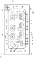
- a top view of an embodiment of a power electronic semiconductor device including a cooling system;
- Fig. 3
- a schematic block diagram of an example of a power module of a power electronic semiconductor device; and
- Fig. 4
- a graphic representing the course of first and second temperatures measured in the power electronic semiconductor device.
-
Fig. 1 shows anaircraft 10 with anelectronic device 12 and a powerelectronic semiconductor device 14 for supplying theelectronic device 12 with electrical power. Theelectronic device 12 can be any electronic device to be used on theaircraft 10, such as a part of a flight computer, a flight controller, an electronic instrument, a computing device, a personal computer, a communication device, a transmitter, a receiver, an electric motor, or a part of a passenger entertainment system. -
Fig. 2 shows a top view of a possible embodiment of the powerelectronic semiconductor device 14. The powerelectronic semiconductor device 14 comprises ahousing 16, acooling system 18 for providing a cooling fluid and at least one semiconductor die 20 including at least onepower switching element 22, e.g., an IGBT. - In some embodiments (not shown), the power
electronic semiconductor device 14 includes a DC switch. In the embodiments shown inFigs. 2 and3 , powerelectronic semiconductor device 14 includes one orseveral power modules 24, e.g. in half-bridge configuration or any other suitable configuration. - The at least one
power module 24 is a power electronics for supplying adequate electrical power to theelectronic device 12. Thepower module 24 transfers power from a DC or AC source (often mains power, e.g., AC adapter) to DC or AC loads, such as a personal computer or an electric motor, while converting voltage and current characteristics. Thepower module 24 has power semiconductors for high current throughput aspower switching elements 22, such as MOSFETs or IGBTs. In some embodiments, thepower module 24 is a switched-mode power supply (SMPS). In some embodiments, thepower module 24 is a simple power module that is only a part of an DC or AC power supply, such as e.g. a SMPS or an inverter. A switched-mode power supply is an electronic power supply that incorporates a switching regulator to convert electrical power efficiently. In some embodiments, thepower module 24 has a half-bridge configuration. - Referring to
Fig. 2 , the powerelectronic semiconductor device 14 includes an isolator such as aceramic substrate 26, several of the semiconductor dies 20, here configured as IGBT dies withIGBT emitter pads 28 and anIGBT gate pad 30, adiode die 32, apower emitter pin 34, aKelvin gate pin 36, aKelvin emitter pin 38, a top bonded copper layer 40 (patterned), atemperature sensor 42 such as a thermistor for measuring a first temperature T1 within thehousing 16, and thecooling system 18. In other embodiments, thepower switching elements 22 are MOSFETs or SiC-elements. - The
pins copper layer 40 to therespective pads power switching elements 22. Thetemperature sensor 42 is arranged on a free space of theceramic substrate 26, and hence with distance to the several semiconductor dies 20. Thus, the temperature T1 measured by thetemperature sensor 42 is mainly the temperature of the cooling fluid that flows from thecooling system 18 over the semiconductor dies 20. - In the following, a method for monitoring the
cooling system 18 is explained with reference toFigs. 2 and3 . - The method comprises:
- a) measuring the first temperature T1 by means of the
temperature sensor 42, - b) measuring an actual junction temperature of the at least one semiconductor die 20 as a second temperature T2, and
- c) comparing the first and second temperatures T1, T2 for determining a health status of the
cooling system 18. - In some embodiments, step b) comprises the steps:
- b1) measuring an actual value of an electrical temperature-dependent resistance of the semiconductor die 20; and
- b2) determining the actual temperature T2 of the semiconductor die 20 from the actual value of the resistance of the semiconductor die 20.
- In the embodiment as shown in
Fig. 3 , step b1) is conducted by measuring an actual source-drain voltage USD and an actual drain current ID of at least one of the power switching elements 22 (e.g., configured as MOSFETs, SiC,...) and determining the actual on-state resistance from the measured voltage USD and the measured current ID. In the embodiment as shown inFig. 3 , thepower module 24 is connected to a measuringunit 50 that is configured to measure the actual source- drain voltage USD and the actual drain current ID of at least one of thepower switching elements 22 and to determine the actual temperature dependent on-state resistance from these measured values. - This works also for IGBTs, e.g., by determining the resistance from the Collector-Emitter Voltage and the Collector current.
- In the embodiments as shown in
Fig. 2 and3 , step b2) is conducted by comparing the actual resistance with pre-calibrated values corresponding to temperature values. In some embodiments of the method a calibrating step is conducted at least once before an operation of the powerelectronic semiconductor device 14, wherein the semiconductor dies 20 are brought to different predefined temperatures, and the resistance of the corresponding semiconductor die 20 at each predefined temperature is measured in order to correlate resistance values and temperature values. Thus, the junction temperature of at least one of the semiconductor dies 20 can be directly measured by determining the actual electrical resistance of the semiconductor die 20. - In some embodiments, step c) comprises at least one or several of the steps:
- c1) monitoring a difference between the first and second temperatures T1, T2;
- c2) comparing a difference between the first and second temperatures with at least one predetermined threshold;
- c3) comparing a change in the difference between the first and second temperatures with a predetermined threshold for the change;
- c4) determining a load of the power electronic semiconductor device and comparing a change of the first and second temperatures with a load change.
- The two temperature values T1 and T2 are coupled by the thermal resistance between each other. For a constant heat load, this results in a constant temperature difference ΔT=T2-T1.
- In case of a cooling issue (e.g. reduced or stopped flow rate), the second temperature T2 of the semiconductor die 20 increases much faster than the first temperature T1 at the
temperature sensor 42 due to a slower temperature dispersion. Hence, an issue with thecooling system 18 can be detected when ΔT exceeds a predetermined threshold during a constant load. - Additionally, the power in the
power module 24 is calculated. Thus, an awaited change of the temperatures T1 and T2 and of the difference ΔT due to a change in power load will not trigger a detection of an issue with the cooling system. - Referring to
Fig. 2 and3 , thepower semiconductor device 14 includes amonitoring unit 52 for monitoring the health status of thecooling system 18. Themonitoring unit 52 comprises: - the
temperature sensor 42 for measuring the actual first temperature T1 of the powerelectronic semiconductor device 14, - the measuring
unit 50 for measuring the actual junction temperature of the at least one semiconductor die as an actual second temperature T2, and - a computing means 54 for conducting the monitoring method.
- Especially, the
monitoring unit 52 is configured to detect an issue of thecooling system 18 by comparing the temperatures T1 and T2, and especially by monitoring the difference ΔT and the power level of thecorresponding power module 24. - In some embodiments, the
monitoring unit 52 has the following mode of operation:
In a normal operation, the second temperature T2 of the semiconductor die 20 and the first temperature T1 of the temperature sensor42 show a constant temperature difference ΔT = T2 - T1 that only depends on the power losses produced by the semiconductor dies 20. - When the module load of the
power module 24 is changed, T1 and T2 also change with different time constants. As the difference in power is known, and a temperature change is estimated, the steady state can be awaited. - In case of an error in the
cooling system 18, there is also a change for T1 and T2 with different time constants but with no change in the load. Since there is no change in the load, the losses are constant, and there is an issue with coolingsystem 18 e.g., to low flow rate, pressure loss, leakage, that can be detected. -
Fig. 4 shows an exemplary increase of the second temperature T2 of the semiconductor die 20 and of the first temperature T1 of thetemperature sensor 42 in case of a cooling issue that starts shortly before the dotted line. - In order to enhance performance of power electronics such as a power switch or a power module, the invention provides a Monitoring method for monitoring a cooling system (18) of a power electronic semiconductor device (14) that includes the cooling system (18) (e.g., for providing a cooling fluid such as a cooling liquid or a cooling gas, especially cooling air) and at least one semiconductor die (20) including a power switching element (22), comprising:
- a) measuring a first temperature (T1) by means of a temperature sensor (42) of the power electronic semiconductor device (14) wherein the temperature sensor (42) is arranged in a distance to the at least one semiconductor die (20),
- b) measuring an actual junction temperature of the at least one semiconductor die (20) as a second temperature (T2), and
- c) comparing the first and second temperatures (T1, T2) for determining a health status of the cooling system (18).
-
- 10
- aircraft
- 12
- electronic device
- 14
- power electronic semiconductor device
- 16
- housing
- 18
- cooling system
- 20
- semiconductor die
- 22
- power switching element
- 24
- power module
- 26
- ceramic substrate
- 28
- IGBT emitter pad
- 30
- IGBT gate pad
- 32
- diode die
- 34
- power emitter pin
- 36
- Kelvin emitter pin
- 38
- Kelvin gate pin
- 40
- copper layer (patterned)
- 42
- temperature sensor
- 44
- wire bond
- 50
- measuring unit
- 52
- monitoring unit
- 54
- computing unit
- USD
- source-drain voltage
- ID
- drain current
- T1
- first temperature
- T2
- second temperature
- T
- temperature
- t
- time
Claims (12)
- Monitoring method for monitoring a cooling system (18) of a power electronic semiconductor device (14) that includes the cooling system (18) and at least one semiconductor die (20) including a power switching element (22), comprising:a) measuring a first temperature (T1) by means of a temperature sensor (42) of the power electronic semiconductor device (14) wherein the temperature sensor (42) is arranged in a distance to the at least one semiconductor die (20),b) measuring an actual junction temperature of the at least one semiconductor die (20) as a second temperature (T2), andc) comparing the first and second temperatures (T1, T2) for determining a health status of the cooling system (18).
- Monitoring method according to claim 1, wherein step a) comprises at least one or several of the steps:a1) using a thermistor as temperature sensor (42);a2) providing the temperature sensor (42) on a circuit board (26) of the power electronic semiconductor device (14).
- Monitoring method according to any of the preceding claims, wherein step b) comprises the steps:b1) measuring an actual value of an electrical temperature-dependent on-state resistance of the semiconductor die (20); andb2) determining the actual temperature of the semiconductor die (20) from the actual value of the on-state resistance of the semiconductor die (20).
- Monitoring method according to claim 3,4.1 wherein step b1) comprises:
b1a) measuring an actual source-drain voltage (USD) and an actual drain current (ID) of the power switching element and determining the actual on-state resistance from the measured voltage (USD) and the measured current (ID); and/or4.2 wherein step b2) comprises:
b2a) comparing the actual on-state resistance with pre-calibrated values corresponding to temperature values. - Monitoring method according to any of the preceding claims, wherein step c) comprises at least one or several of the steps:c1) monitoring a difference between the first and second temperatures (T1, T2);c2) comparing a difference between the first and second temperatures (T1, T2) with at least one predetermined threshold;c3) comparing a change in the difference between the first and second temperatures (T1, T2) with a predetermined threshold for the change;c4) determining a load of the power electronic semiconductor device (14) and comparing a change of the first and second temperatures (T1, T2) with a load change.
- Monitoring unit (52) for monitoring a cooling system (18) of a power electronic semiconductor device (14) that includes the cooling system (18) and at least one semiconductor die (20) including a power switching element (22), the monitoring unit (52) comprising:a temperature sensor (42) for measuring an actual first temperature (T1) of the power electronic semiconductor device (14) wherein the temperature sensor (42) is configured to be arranged in a distance to the at least one semiconductor die (20),a measuring unit (50) for measuring an actual junction temperature of the at least one semiconductor die (20) as an actual second temperature (T2), anda computing unit (54) configured to compare the first and second temperatures (T1, T2) for determining a health status of the cooling system (18).
- Monitoring unit (52) according to claim 6, configured to conduct the monitoring method according to any of the claims 1 to 5.
- Power electronic semiconductor device (14) comprising a cooling system (18), at least one semiconductor die (20) including a power switching element (22), and a monitoring unit according to claim 6 or 7.
- Power electronic semiconductor device (14) according to claim 8, further comprising a housing (16), wherein the cooling system (18) is configured to provide a cooling fluid flow within the housing (16) and the temperature sensor (42) is in indirect contact with the cooling fluid.
- Aircraft (10) comprising a power electronic semiconductor device (14) according to any of the claims 8 or 9 and/or a monitoring unit according to any of the claims 6 or 7.
- Computing unit (54) for a monitoring unit (52) according to claim 6 or 7, configured to control the monitoring unit (52) to conduct the monitoring method according to any of the claims 1 to 5.
- Computer program comprising instructions to cause the power electronic semiconductor device (14) of any of the claims 8 or 9 or the monitoring unit (52) of any of the claims 6 or 7 to execute the steps of the method of any of the claims 1 to 5.
Priority Applications (1)
| Application Number | Priority Date | Filing Date | Title |
|---|---|---|---|
| EP23188646.6A EP4502562B1 (en) | 2023-07-31 | 2023-07-31 | Monitoring a cooling system of a power electronic semiconductor device |
Applications Claiming Priority (1)
| Application Number | Priority Date | Filing Date | Title |
|---|---|---|---|
| EP23188646.6A EP4502562B1 (en) | 2023-07-31 | 2023-07-31 | Monitoring a cooling system of a power electronic semiconductor device |
Publications (2)
| Publication Number | Publication Date |
|---|---|
| EP4502562A1 true EP4502562A1 (en) | 2025-02-05 |
| EP4502562B1 EP4502562B1 (en) | 2026-01-21 |
Family
ID=87551190
Family Applications (1)
| Application Number | Title | Priority Date | Filing Date |
|---|---|---|---|
| EP23188646.6A Active EP4502562B1 (en) | 2023-07-31 | 2023-07-31 | Monitoring a cooling system of a power electronic semiconductor device |
Country Status (1)
| Country | Link |
|---|---|
| EP (1) | EP4502562B1 (en) |
Cited By (1)
| Publication number | Priority date | Publication date | Assignee | Title |
|---|---|---|---|---|
| CN121995151A (en) * | 2026-04-10 | 2026-05-08 | 宁波腾浪网络通信设备有限公司 | Control method and device of load simulation device for soft start test of cabinet |
Citations (2)
| Publication number | Priority date | Publication date | Assignee | Title |
|---|---|---|---|---|
| US20210396600A1 (en) * | 2020-06-22 | 2021-12-23 | Bayerische Motoren Werke Aktiengesellschaft | Method and Electronic Device for Monitoring the Temperature of Power Electronics, and Motor Vehicle |
| US20220140455A1 (en) * | 2020-10-29 | 2022-05-05 | Zf Friedrichshafen Ag | Device and method for measuring the temperature of a cooling medium for an inverter, inverter with such a device |
-
2023
- 2023-07-31 EP EP23188646.6A patent/EP4502562B1/en active Active
Patent Citations (2)
| Publication number | Priority date | Publication date | Assignee | Title |
|---|---|---|---|---|
| US20210396600A1 (en) * | 2020-06-22 | 2021-12-23 | Bayerische Motoren Werke Aktiengesellschaft | Method and Electronic Device for Monitoring the Temperature of Power Electronics, and Motor Vehicle |
| US20220140455A1 (en) * | 2020-10-29 | 2022-05-05 | Zf Friedrichshafen Ag | Device and method for measuring the temperature of a cooling medium for an inverter, inverter with such a device |
Cited By (1)
| Publication number | Priority date | Publication date | Assignee | Title |
|---|---|---|---|---|
| CN121995151A (en) * | 2026-04-10 | 2026-05-08 | 宁波腾浪网络通信设备有限公司 | Control method and device of load simulation device for soft start test of cabinet |
Also Published As
| Publication number | Publication date |
|---|---|
| EP4502562B1 (en) | 2026-01-21 |
Similar Documents
| Publication | Publication Date | Title |
|---|---|---|
| US11248966B2 (en) | Health monitoring and failure prognosis of power electronics devices | |
| Choi et al. | Power cycling test methods for reliability assessment of power device modules in respect to temperature stress | |
| CN110710095B (en) | Power conversion device, motor control system, and diagnostic method for power conversion device | |
| KR102294347B1 (en) | Junction Temperature and Current Sensing Techniques | |
| US7904254B2 (en) | Power conversion apparatus and method of estimating power cycle life | |
| EP3614551B1 (en) | Power conversion device, diagnosis system for same, diagnosis method, and electric motor control system using said diagnosis method | |
| JP6522232B2 (en) | Overheat protection control device and power circuit device for vehicle | |
| CN111830389B (en) | IGBT junction temperature estimation system and method based on emitter power terminal temperature | |
| US20160313191A1 (en) | Method and apparatus for determining an actual junction temperature of an igbt device | |
| KR101655533B1 (en) | Temperature sensing system for switching device | |
| CN108450018A (en) | Method and device for detecting aging of a power electronic device comprising semiconductor components and power electronic system | |
| CN103620429A (en) | Method for estimating the end of lifetime for a power semiconductor device | |
| EP4502562B1 (en) | Monitoring a cooling system of a power electronic semiconductor device | |
| CN110274707A (en) | Monitoring to the operating status of (PCC) power | |
| Chen et al. | Driver Integrated Online R ds-on Monitoring Method for SiC Power Converters | |
| JP7799900B2 (en) | Method for measuring temperature or thermal resistance and monitoring thermal resistance | |
| CN208833885U (en) | Circuit system | |
| KR20160086073A (en) | Device of testing power semiconductor module and testing method using the same | |
| JP2019187030A (en) | Power conversion apparatus | |
| CN108291843A (en) | Semiconductor component with the first temperature-measuring element and the method for determining the electric current for flowing through semiconductor component | |
| JPH1144727A (en) | Circuit board inspection equipment | |
| CN208384442U (en) | Temperature sensing circuit and temperature-detecting device | |
| EP4633305A1 (en) | Monitoring a coolant flow of a power electronic semiconductor device | |
| Riefer et al. | Substrate integrated temperature sensing for bondless power modules | |
| US20250297900A1 (en) | Estimation apparatus, current sensor, system, and estimation method |
Legal Events
| Date | Code | Title | Description |
|---|---|---|---|
| PUAI | Public reference made under article 153(3) epc to a published international application that has entered the european phase |
Free format text: ORIGINAL CODE: 0009012 |
|
| STAA | Information on the status of an ep patent application or granted ep patent |
Free format text: STATUS: THE APPLICATION HAS BEEN PUBLISHED |
|
| AK | Designated contracting states |
Kind code of ref document: A1 Designated state(s): AL AT BE BG CH CY CZ DE DK EE ES FI FR GB GR HR HU IE IS IT LI LT LU LV MC ME MK MT NL NO PL PT RO RS SE SI SK SM TR |
|
| STAA | Information on the status of an ep patent application or granted ep patent |
Free format text: STATUS: REQUEST FOR EXAMINATION WAS MADE |
|
| GRAP | Despatch of communication of intention to grant a patent |
Free format text: ORIGINAL CODE: EPIDOSNIGR1 |
|
| STAA | Information on the status of an ep patent application or granted ep patent |
Free format text: STATUS: GRANT OF PATENT IS INTENDED |
|
| 17P | Request for examination filed |
Effective date: 20250805 |
|
| RIC1 | Information provided on ipc code assigned before grant |
Ipc: G01K 7/01 20060101AFI20250815BHEP Ipc: G01K 7/22 20060101ALI20250815BHEP Ipc: G01K 3/14 20060101ALI20250815BHEP |
|
| INTG | Intention to grant announced |
Effective date: 20250905 |
|
| GRAS | Grant fee paid |
Free format text: ORIGINAL CODE: EPIDOSNIGR3 |
|
| GRAA | (expected) grant |
Free format text: ORIGINAL CODE: 0009210 |
|
| STAA | Information on the status of an ep patent application or granted ep patent |
Free format text: STATUS: THE PATENT HAS BEEN GRANTED |
|
| AK | Designated contracting states |
Kind code of ref document: B1 Designated state(s): AL AT BE BG CH CY CZ DE DK EE ES FI FR GB GR HR HU IE IS IT LI LT LU LV MC ME MK MT NL NO PL PT RO RS SE SI SK SM TR |
|
| REG | Reference to a national code |
Ref country code: CH Ref legal event code: F10 Free format text: ST27 STATUS EVENT CODE: U-0-0-F10-F00 (AS PROVIDED BY THE NATIONAL OFFICE) Effective date: 20260121 |
|
| REG | Reference to a national code |
Ref country code: DE Ref legal event code: R096 Ref document number: 602023010942 Country of ref document: DE |
|
| REG | Reference to a national code |
Ref country code: IE Ref legal event code: FG4D |
|
| REG | Reference to a national code |
Ref country code: NL Ref legal event code: MP Effective date: 20260121 |
|
| PG25 | Lapsed in a contracting state [announced via postgrant information from national office to epo] |
Ref country code: NL Free format text: LAPSE BECAUSE OF FAILURE TO SUBMIT A TRANSLATION OF THE DESCRIPTION OR TO PAY THE FEE WITHIN THE PRESCRIBED TIME-LIMIT Effective date: 20260121 |
|
| REG | Reference to a national code |
Ref country code: AT Ref legal event code: MK05 Ref document number: 1879069 Country of ref document: AT Kind code of ref document: T Effective date: 20260121 |
|
| PG25 | Lapsed in a contracting state [announced via postgrant information from national office to epo] |
Ref country code: RS Free format text: LAPSE BECAUSE OF FAILURE TO SUBMIT A TRANSLATION OF THE DESCRIPTION OR TO PAY THE FEE WITHIN THE PRESCRIBED TIME-LIMIT Effective date: 20260421 |
|
| PG25 | Lapsed in a contracting state [announced via postgrant information from national office to epo] |
Ref country code: ES Free format text: LAPSE BECAUSE OF FAILURE TO SUBMIT A TRANSLATION OF THE DESCRIPTION OR TO PAY THE FEE WITHIN THE PRESCRIBED TIME-LIMIT Effective date: 20260121 |
|
| PG25 | Lapsed in a contracting state [announced via postgrant information from national office to epo] |
Ref country code: PL Free format text: LAPSE BECAUSE OF FAILURE TO SUBMIT A TRANSLATION OF THE DESCRIPTION OR TO PAY THE FEE WITHIN THE PRESCRIBED TIME-LIMIT Effective date: 20260121 |
|
| PG25 | Lapsed in a contracting state [announced via postgrant information from national office to epo] |
Ref country code: GR Free format text: LAPSE BECAUSE OF FAILURE TO SUBMIT A TRANSLATION OF THE DESCRIPTION OR TO PAY THE FEE WITHIN THE PRESCRIBED TIME-LIMIT Effective date: 20260422 |
|
| REG | Reference to a national code |
Ref country code: LT Ref legal event code: MG9D |
|
| PG25 | Lapsed in a contracting state [announced via postgrant information from national office to epo] |
Ref country code: LT Free format text: LAPSE BECAUSE OF FAILURE TO SUBMIT A TRANSLATION OF THE DESCRIPTION OR TO PAY THE FEE WITHIN THE PRESCRIBED TIME-LIMIT Effective date: 20260121 |
|
| PG25 | Lapsed in a contracting state [announced via postgrant information from national office to epo] |
Ref country code: NO Free format text: LAPSE BECAUSE OF FAILURE TO SUBMIT A TRANSLATION OF THE DESCRIPTION OR TO PAY THE FEE WITHIN THE PRESCRIBED TIME-LIMIT Effective date: 20260421 |
|
| PG25 | Lapsed in a contracting state [announced via postgrant information from national office to epo] |
Ref country code: SE Free format text: LAPSE BECAUSE OF FAILURE TO SUBMIT A TRANSLATION OF THE DESCRIPTION OR TO PAY THE FEE WITHIN THE PRESCRIBED TIME-LIMIT Effective date: 20260121 Ref country code: AT Free format text: LAPSE BECAUSE OF FAILURE TO SUBMIT A TRANSLATION OF THE DESCRIPTION OR TO PAY THE FEE WITHIN THE PRESCRIBED TIME-LIMIT Effective date: 20260121 Ref country code: FI Free format text: LAPSE BECAUSE OF FAILURE TO SUBMIT A TRANSLATION OF THE DESCRIPTION OR TO PAY THE FEE WITHIN THE PRESCRIBED TIME-LIMIT Effective date: 20260121 |
|
| PG25 | Lapsed in a contracting state [announced via postgrant information from national office to epo] |
Ref country code: HR Free format text: LAPSE BECAUSE OF FAILURE TO SUBMIT A TRANSLATION OF THE DESCRIPTION OR TO PAY THE FEE WITHIN THE PRESCRIBED TIME-LIMIT Effective date: 20260121 |
|
| PG25 | Lapsed in a contracting state [announced via postgrant information from national office to epo] |
Ref country code: PT Free format text: LAPSE BECAUSE OF FAILURE TO SUBMIT A TRANSLATION OF THE DESCRIPTION OR TO PAY THE FEE WITHIN THE PRESCRIBED TIME-LIMIT Effective date: 20260521 Ref country code: IS Free format text: LAPSE BECAUSE OF FAILURE TO SUBMIT A TRANSLATION OF THE DESCRIPTION OR TO PAY THE FEE WITHIN THE PRESCRIBED TIME-LIMIT Effective date: 20260521 |
|
| PG25 | Lapsed in a contracting state [announced via postgrant information from national office to epo] |
Ref country code: LV Free format text: LAPSE BECAUSE OF FAILURE TO SUBMIT A TRANSLATION OF THE DESCRIPTION OR TO PAY THE FEE WITHIN THE PRESCRIBED TIME-LIMIT Effective date: 20260121 |
|
| PG25 | Lapsed in a contracting state [announced via postgrant information from national office to epo] |
Ref country code: BG Free format text: LAPSE BECAUSE OF FAILURE TO SUBMIT A TRANSLATION OF THE DESCRIPTION OR TO PAY THE FEE WITHIN THE PRESCRIBED TIME-LIMIT Effective date: 20260121 |