EP4502511A1 - Support system for a vacuum insulated panel - Google Patents
Support system for a vacuum insulated panel Download PDFInfo
- Publication number
- EP4502511A1 EP4502511A1 EP24192486.9A EP24192486A EP4502511A1 EP 4502511 A1 EP4502511 A1 EP 4502511A1 EP 24192486 A EP24192486 A EP 24192486A EP 4502511 A1 EP4502511 A1 EP 4502511A1
- Authority
- EP
- European Patent Office
- Prior art keywords
- panel
- inner panel
- bracket assembly
- vacuum
- bracket
- Prior art date
- Legal status (The legal status is an assumption and is not a legal conclusion. Google has not performed a legal analysis and makes no representation as to the accuracy of the status listed.)
- Withdrawn
Links
Images






Classifications
-
- F—MECHANICAL ENGINEERING; LIGHTING; HEATING; WEAPONS; BLASTING
- F25—REFRIGERATION OR COOLING; COMBINED HEATING AND REFRIGERATION SYSTEMS; HEAT PUMP SYSTEMS; MANUFACTURE OR STORAGE OF ICE; LIQUEFACTION SOLIDIFICATION OF GASES
- F25D—REFRIGERATORS; COLD ROOMS; ICE-BOXES; COOLING OR FREEZING APPARATUS NOT OTHERWISE PROVIDED FOR
- F25D23/00—General constructional features
- F25D23/02—Doors; Covers
- F25D23/04—Doors; Covers with special compartments, e.g. butter conditioners
-
- F—MECHANICAL ENGINEERING; LIGHTING; HEATING; WEAPONS; BLASTING
- F25—REFRIGERATION OR COOLING; COMBINED HEATING AND REFRIGERATION SYSTEMS; HEAT PUMP SYSTEMS; MANUFACTURE OR STORAGE OF ICE; LIQUEFACTION SOLIDIFICATION OF GASES
- F25D—REFRIGERATORS; COLD ROOMS; ICE-BOXES; COOLING OR FREEZING APPARATUS NOT OTHERWISE PROVIDED FOR
- F25D23/00—General constructional features
- F25D23/02—Doors; Covers
- F25D23/028—Details
-
- F—MECHANICAL ENGINEERING; LIGHTING; HEATING; WEAPONS; BLASTING
- F25—REFRIGERATION OR COOLING; COMBINED HEATING AND REFRIGERATION SYSTEMS; HEAT PUMP SYSTEMS; MANUFACTURE OR STORAGE OF ICE; LIQUEFACTION SOLIDIFICATION OF GASES
- F25D—REFRIGERATORS; COLD ROOMS; ICE-BOXES; COOLING OR FREEZING APPARATUS NOT OTHERWISE PROVIDED FOR
- F25D23/00—General constructional features
- F25D23/06—Walls
- F25D23/065—Details
- F25D23/067—Supporting elements
-
- F—MECHANICAL ENGINEERING; LIGHTING; HEATING; WEAPONS; BLASTING
- F25—REFRIGERATION OR COOLING; COMBINED HEATING AND REFRIGERATION SYSTEMS; HEAT PUMP SYSTEMS; MANUFACTURE OR STORAGE OF ICE; LIQUEFACTION SOLIDIFICATION OF GASES
- F25D—REFRIGERATORS; COLD ROOMS; ICE-BOXES; COOLING OR FREEZING APPARATUS NOT OTHERWISE PROVIDED FOR
- F25D2201/00—Insulation
- F25D2201/10—Insulation with respect to heat
- F25D2201/14—Insulation with respect to heat using subatmospheric pressure
-
- F—MECHANICAL ENGINEERING; LIGHTING; HEATING; WEAPONS; BLASTING
- F25—REFRIGERATION OR COOLING; COMBINED HEATING AND REFRIGERATION SYSTEMS; HEAT PUMP SYSTEMS; MANUFACTURE OR STORAGE OF ICE; LIQUEFACTION SOLIDIFICATION OF GASES
- F25D—REFRIGERATORS; COLD ROOMS; ICE-BOXES; COOLING OR FREEZING APPARATUS NOT OTHERWISE PROVIDED FOR
- F25D2325/00—Charging, supporting or discharging the articles to be cooled, not provided for in other groups of this subclass
- F25D2325/021—Shelves with several possible configurations
-
- Y—GENERAL TAGGING OF NEW TECHNOLOGICAL DEVELOPMENTS; GENERAL TAGGING OF CROSS-SECTIONAL TECHNOLOGIES SPANNING OVER SEVERAL SECTIONS OF THE IPC; TECHNICAL SUBJECTS COVERED BY FORMER USPC CROSS-REFERENCE ART COLLECTIONS [XRACs] AND DIGESTS
- Y02—TECHNOLOGIES OR APPLICATIONS FOR MITIGATION OR ADAPTATION AGAINST CLIMATE CHANGE
- Y02A—TECHNOLOGIES FOR ADAPTATION TO CLIMATE CHANGE
- Y02A30/00—Adapting or protecting infrastructure or their operation
- Y02A30/24—Structural elements or technologies for improving thermal insulation
- Y02A30/242—Slab shaped vacuum insulation
-
- Y—GENERAL TAGGING OF NEW TECHNOLOGICAL DEVELOPMENTS; GENERAL TAGGING OF CROSS-SECTIONAL TECHNOLOGIES SPANNING OVER SEVERAL SECTIONS OF THE IPC; TECHNICAL SUBJECTS COVERED BY FORMER USPC CROSS-REFERENCE ART COLLECTIONS [XRACs] AND DIGESTS
- Y02—TECHNOLOGIES OR APPLICATIONS FOR MITIGATION OR ADAPTATION AGAINST CLIMATE CHANGE
- Y02B—CLIMATE CHANGE MITIGATION TECHNOLOGIES RELATED TO BUILDINGS, e.g. HOUSING, HOUSE APPLIANCES OR RELATED END-USER APPLICATIONS
- Y02B80/00—Architectural or constructional elements improving the thermal performance of buildings
- Y02B80/10—Insulation, e.g. vacuum or aerogel insulation
Definitions
- the present disclosure generally relates to a vacuum insulated panel, and more specifically, to a vacuum insulated panel having a support system configured to support multiple bin assemblies.
- a door includes an outer panel having a generally planar body portion with inner and outer surfaces and a sidewall with a front edge.
- the sidewall of the outer panel extends outwardly from the inner surface of the body portion of the outer panel.
- the door further includes an inner panel having a generally planar body portion with inner and outer surfaces, a sidewall with a front edge, and at least one elongate slot disposed vertically along the generally planar body portion.
- the sidewall of the inner panel extends outwardly from the inner surface of the body portion of the inner panel.
- the door further includes a trim breaker interconnecting the outer panel and the inner panel to form a vacuum cavity therebetween.
- the door further includes at least one bracket assembly positioned within the vacuum cavity of the door and coupled to the inner surface of the inner panel.
- the at least one bracket assembly is aligned with the at least one elongate slot of the inner panel to provide access to the at least one bracket assembly therethrough.
- a vacuum insulated panel includes an outer panel and an inner panel operably coupled to the outer panel to define a vacuum cavity therebetween.
- the inner panel includes at least one elongate slot disposed therethrough and positioned vertically therealong, and at least one bracket assembly positioned within the vacuum cavity and coupled to an inner surface of the inner panel.
- the at least one bracket assembly is aligned with the at least one elongate slot of the inner panel to provide access to the at least one bracket assembly therethrough.
- a vacuum insulated panel includes an outer panel and an inner panel operably coupled to the outer panel to define a vacuum cavity therebetween.
- the inner panel includes a body portion having inner and outer surfaces.
- the inner panel further includes first and second slots disposed through the body portion that are spaced-apart from one another.
- a first bracket assembly is operably coupled to the inner surface of the inner panel.
- the first bracket assembly covers the first slot of the inner panel.
- a second bracket assembly is operably coupled to the inner surface of the inner panel.
- the second bracket assembly covers the second slot of the inner panel.
- the present illustrated embodiments reside primarily in combinations of method steps and apparatus components related to a vacuum insulated door panel configured to support multiple bin assemblies. Accordingly, the apparatus components and method steps have been represented, where appropriate, by conventional symbols in the drawings, showing only those specific details that are pertinent to understanding the embodiments of the present disclosure so as not to obscure the disclosure with details that will be readily apparent to those of ordinary skill in the art having the benefit of the description herein. Further, like numerals in the description and drawings represent like elements.
- the terms “upper,” “lower,” “right,” “left,” “rear,” “front,” “vertical,” “horizontal,” and derivatives thereof shall relate to the disclosure as oriented in FIG. 1 .
- the term “front” shall refer to the surface of the element closer to an intended viewer, and the term “rear” shall refer to the surface of the element further from the intended viewer.
- the disclosure may assume various alternative orientations, except where expressly specified to the contrary.
- the specific devices and processes illustrated in the attached drawings, and described in the following specification are simply exemplary embodiments of the inventive concepts defined in the appended claims. Hence, specific dimensions and other physical characteristics relating to the embodiments disclosed herein are not to be considered as limiting, unless the claims expressly state otherwise.
- reference numeral 10 generally designates a door for an appliance 2, and more specifically, a vacuum insulated door.
- the appliance 2 is illustrated as a refrigerator appliance, however, it is contemplated that the door 10 disclosed herein may be used with a variety of appliances, structures, or for insulation purposes other than those associated with a refrigerator appliance.
- the illustrated appliance 2 is a bottom mount refrigerator having the door 10 and a second door 5.
- the second door 5 is also contemplated to be a vacuum insulated door.
- the appliance 2 includes a cabinet 3 that defines a first compartment 4 and a second compartment 6.
- the insulated door 10 is contemplated to be rotatably coupled to the cabinet 3 for selectively providing access to the first compartment 4, which may be a refrigerator compartment.
- the second insulated door 5 is contemplated to be slideably coupled to the cabinet 3 in a drawer-like manner for selectively providing access to the second compartment 6, which may be a freezer compartment.
- the cabinet 3 of the appliance 2 is an insulated structure having a cabinet wrapper 7 with a first liner 8A and a second liner 8B positioned therein to define a vacuum insulating space 9 therebetween.
- the appliance 2 can be a bottom mount refrigerator, a bottom mount French door refrigerator, a top mount refrigerator, a side-by-side refrigerator, a four-door French door refrigerator, and/or a five door French door refrigerator, each of which can have one or more insulated doors 10.
- the insulated door 10 is a vacuum insulated panel. As illustrated in FIGS. 1-5 , the insulated door 10 includes an outer panel 12 coupled with an inner panel 14 to thereby define a vacuum cavity 16 therebetween.
- the vacuum cavity 16 defines an insulating cavity for the door 10.
- the outer panel 12 and the inner panel 14 may alternatively be referred to as a structural wrapper that defines the vacuum cavity 16.
- the vacuum cavity 16 of the insulated door 10 and the insulating space 9 of the cabinet 3 typically includes one or more insulation materials disposed therein.
- the insulation materials may substantially fill the vacuum cavity 16 of the door 10, thereby forming a substantially continuous layer between the outer panel 12 and the inner panel 14 of the door 10.
- the insulation materials may substantially fill the insulating space 9 of the cabinet, thereby forming a substantially continuous layer between the cabinet wrapper 7 and the first and second liners 8A, 8B.
- the appliance 2 includes two insulated doors 10, 5.
- first and second compartments 4, 6 defined by the cabinet 3 can each be sealed with an insulated door 10, 5, respectively.
- the outer panel 12 and the inner panel 14 of the doors 10, 5 may be made from a material at least partially resistant to bending, deformation, or otherwise being formed in response to an inward compressive force 20, as best shown in FIG. 5 .
- These materials for the outer panel 12 and the inner panel 14 include, but are not limited to, metals, polymers, metal alloys, combinations thereof, and/or other similar substantially rigid materials that can be used for vacuum insulated structures.
- a vacuum 22 is defined within the vacuum cavity 16 of the door 10.
- the vacuum 22 defines a pressure differential 24 between an exterior 26 or outside environment of the insulated door 10 and the vacuum cavity 16 disposed within the door 10.
- the pressure differential 24 serves to define the inward compressive force 20 that is exerted on both the outer panel 12 and the inner panel 14.
- the inward compressive force 20 tends to bias the outer panel 12 and the inner panel 14 toward one another and toward the vacuum cavity 16.
- the vacuum 22 is typically defined by evacuation of the insulated door 10 at an evacuation port which is later sealed after an evacuation procedure. Over time, gas can infiltrate into the vacuum cavity 16 from an area outside the appliance 2, which can diminish the negative pressure of the vacuum 22.
- gas permeation The infiltration of gas is sometimes referred to as gas permeation, which can result in a decrease in the partial vacuum 22 over time. Gas permeation leads to a reduced vacuum pressure which then leads to reduced insulative properties, so every effort is made to keep the insulting cavity 16 a sealed cavity. This can make the mounting of bin assemblies and storage shelves to the door 10 difficult as standard mounting techniques are often not available for a vacuum insulated door. Such techniques not suited for a vacuum insulated door include the mounting of bracket assemblies to the inner panel 14 with fasteners. When mounting such brackets, the fasteners would create holes in the inner panel 14 that can lead to increased gas permeation and possibly total loss of the vacuum 22 within the vacuum cavity 16 of the door 10.
- the door 10 is shown having a support system 30 for supporting a plurality of bin assemblies 31A.
- Each bin assembly of the plurality of bin assemblies 31A is configured to couple to the support system 30 at a multitude of vertical locations along the support system 30, as further described below.
- the support system 30 of the door 10 is shown having a single bin assembly 31 coupled thereto.
- the door 10 includes an exterior side 10A and an interior side 10B.
- the support system 30 includes first and second upright bracket assemblies 32, 34 that are accessible through the inner panel 14 on the interior side 10B of the door 10, as further described below.
- the outer panel 12 and the inner panel 14 are interconnected by a trim breaker 70, to form the vacuum cavity 16 therebetween.
- the trim breaker 70 is contemplated to be a polymeric member formed from a suitable material that is substantially impervious to gasses to maintain the vacuum 22 in the vacuum cavity 16 defined between the outer panel 12 and the inner panel 14 as interconnected by the trim breaker 70.
- the material composition of the trim breaker 70 is also contemplated to include a low coefficient of thermal conductivity to reduce or prevent transfer of heat between the outer panel 12 and the inner panel 14.
- the trim breaker 70 may be formed utilizing a polymeric material in an injection molding process.
- Other materials suitable to form the trim breaker 70 may include, but are not limited to, polyureas, polyisocyanurates, polyesters, polyphenols, polyepoxides, thermoplastic elastomers, polycarbonate, and nylon materials. It is further contemplated that the trim breaker 70 may be overmolded to the outer panel 12 and the inner panel 14 at perimeter edges thereof.
- the door 10 can be a unitary part after the trim breaker 70 is cast onto the perimeter edges of the outer panel 12 and the inner panel 14. Further, it is contemplated that portions of the inner panel 14 and the outer panel 12 can be coupled to coupling features of the trim breaker 70 and retained therein using an adhesive as further described below.
- the outer panel 12 of the door 10 includes a generally planar body portion 40 with an inner surface 42 and an outer surface 44.
- the outer panel 12 may include an access aperture 46 disposed therethrough which can be used to fill the door 10 with an insulating material and may also be used as an evacuation port to draw a vacuum on the door 10, as described herein.
- the outer surface 44 of the body portion 40 of the outer panel 12 defines the exterior side 10A ( FIG. 2 ) of the door 10 as assembled. As further shown in FIG.
- the outer panel 12 includes a sidewall 48 extending outwardly from the generally planar body portion 40 of the outer panel 12 along a periphery 49 thereof.
- the sidewall 48 of the outer panel 12 includes a front edge 48A which is configured to be received in a channel of the trim breaker 70, as further described below with reference to FIG. 16 , to connect the outer panel 12 to the trim breaker 70.
- the inner panel 14 like the outer panel 12, includes a generally planar body portion 50 having an inner surface 54 and an outer surface 52.
- the outer surface 52 of the body portion 50 of the outer panel 12 defines the interior side 10B ( FIG. 2 ) of the door 10 as assembled.
- the inner panel 14 further includes a sidewall 58 extending outwardly from the generally planar body portion 50 of the inner panel 14 along a periphery 59 thereof.
- the sidewall 58 of the inner panel 14 includes a front edge 58A which is configured to be received in a channel of the trim breaker 70, as further described below with reference to FIG. 16 , to connect the outer panel 12 to the trim breaker 70.
- the sidewalls 48, 58 of the outer and inner panels 12, 14, respectively, are contemplated to be disposed around the entire periphery 49, 59 of the body portions 40, 50 of the respective outer and inner panels 12, 14.
- the inner panel 14 includes first and second elongate slots 62, 64 that are spaced-apart from one another and disposed through the body portion 50 of inner panel 14 in an upright or vertical configuration along the inner panel 14.
- the first and second elongate slots 62, 64 of the inner panel 14 are configured to align with the first and second upright bracket assemblies 32, 34 in a manner as shown in FIG. 2 to provide access to the same.
- the first and second elongate slots 62, 64 may be configured to run, in a vertical direction, the entire length of the inner panel 14. More preferably, the first and second elongate slots 62, 64 run a length that is more than 50% of the length of the inner panel 14.
- the trim breaker 70 is shown having a frame assembly 72 surrounding an open window 74.
- the frame assembly 72 of the trim breaker 70 is defined by first and second upright members 76, 78 which are spaced-apart from one another and interconnected by upper and lower cross members 80, 82.
- the first and second upright members 76, 78 and upper and lower cross members 80, 82 are interconnected, such that the trim breaker 70 is contemplated to be a unitary member.
- the bin assembly 31 and the first and second upright bracket assemblies 32, 34 are shown exploded away from the inner panel 14.
- the first and second upright bracket assemblies 32, 34 are configured to couple to the inner surface 54 of the inner panel 14 in alignment with the first and second elongate slots 62, 64 of the inner panel 14, respectively.
- the bin assembly 31 includes a number of engagement members that are configured to engage the first and second upright bracket assemblies 32, 34 to support the bin assembly 31 at a multitude of vertical locations therealong.
- FIG. 4 the door 10 of FIG. 3 is shown in an assembled condition from the interior side 10B thereof.
- the trim breaker 70 is shown having an inner channel 84 and an outer channel 86 spaced-apart from one another. Both the inner channel 84 and the outer channel 86 are forwardly opening channels that are configured to receive front edges 48A, 58A of the sidewalls 48, 58 of the outer panel 12 and the inner panel 14, respectively.
- the interconnection of the inner panel 14 with the inner channel 84 of the trim breaker 70 and the outer panel 12 with the outer channel 86 of the trim breaker is best shown in FIG. 16 .
- the inner channel 84 and the outer channel 86 are contemplated to be continuously disposed around the entirety of the frame assembly 72 of the trim breaker 70 along the first and second upright members 76, 78 and the upper and lower cross members 80, 82.
- the outer channel 86 surrounds the inner channel 84, such that the outer channel 86 is disposed outwardly around the inner channel 84.
- the outer channel 86 is disposed adjacent to a perimeter of the trim breaker 70, while the inner channel 84 is inset from the perimeter of the trim breaker 70. Further, the outer channel 86 is disposed in forward position relative to the inner channel 84. Said differently, the inner channel 84 inset from the outer channel 86 relative to the exterior side 10A of the door 10.
- the vacuum cavity 16 is configured to receive an insulating material that may be described as a vacuum core material.
- the vacuum core material may comprise a plurality of individual core panels that are preformed and positioned between the outer panel 12, the inner panel 14 and the trim breaker 70.
- the vacuum core material may comprise a silica powder or other suitable loose filler or free-flowing material that is inserted (e.g. poured, blown, compacted) into the vacuum cavity 16, after the outer panel 12 and the inner panel 14 are interconnected by the trim breaker 70.
- This free-flowing material can be in the form of various silica-based materials, such as fumed silica, precipitated silica, nano-sized, and/or micro-sized aerogel powder, rice husk ash powder, perlite, glass spheres, hollow glass spheres, cenospheres, diatomaceous earth, combinations thereof, and other similar insulating particulate material.
- the core material may be inserted into the vacuum cavity 16 through the access aperture 46 of the outer panel 12, which opens into the vacuum cavity 16.
- the trim breaker 70 is contemplated to engage the outer panel 12 and the inner panel 14 in a sealed manner so as to create an airtight cavity within the vacuum cavity 16.
- the door 10 is capable of having the vacuum 22 drawn within the vacuum cavity 16, and maintaining the vacuum 22 given the sealed connections between the trim breaker 70, the outer panel 12 and the inner panel 14. Further, the vacuum 22 is maintained within the vacuum cavity 16 of the door 10 in part by the sheet metal materials of the inner and outer panels 14, 12 and the gas impervious polymeric materials of the trim breaker 70.
- the vacuum 22 may have a pressure level of less than 1 atm, about 0.5 atm, about 0.4 atm, about 0.3 atm, about 0.2 atm, about 0.1 atm, about 0.01 atm, or less than about 0.001 atm.
- the cross-section view of the inner panel 14 shows that the first and second elongate slots 62, 64 each include an inwardly extending rim portion 66, 68, respectively.
- the rim portions 66, 68 fully surround the first and second elongate slots 62, 64 and extend inwardly in an opposite direction relative to the sidewall 58 of the inner panel 14. This configuration is better shown in FIG. 7 .
- the inwardly extending rim portions 66, 68 are configured to abut the first and second bracket assemblies 32, 34 as further described below with reference to FIG. 15 to provide a clean aesthetic to the access point of the first and second bracket assemblies 32, 34.
- the first elongate slot 62 includes a width 62A that defines a width of the opening of the first elongate slot 62.
- the second elongate slot 64 is also similarly configured with a width of the same size as width 62A.
- the inwardly extending rim portion 66 of the first elongate slot 62 culminates in a rear edge portion 66A.
- the upper and lower hook members 100A, 100B and 102A, 102B are disposed on opposite sides of the bin assembly 31 and are configured to removeably couple the bin assembly 31 to the first and second bracket assemblies 32, 34, as shown in FIGS. 2 and 4 . As further shown in FIG. 8 , the upper and lower hook members 100A, 100B and 102A, 102B rearwardly extend from a rear portion 31B of the bin assembly 31.
- the bracket insert 112 is an elongate member that includes a front wall 124 having an outer surface 124A that is substantially flat.
- An opening 126 is centrally disposed along the front wall 124 and is an elongate opening running substantially the length of the bracket insert 112.
- the bracket insert 112 further includes a sidewall 128 that extends rearwardly from the front wall 124 to a substantially flat edge portion 128A.
- the sidewall 128 surrounds the opening 126 and includes first and second sidewall portions 129A, 129B that are spaced-apart from one another and interconnected by cross members 130 that are evenly spaced-apart along a length of the opening 126.
- the cross members 130 define a plurality of cross members 130A ( FIG.
- the receiving space 119 extends inwardly into the vacuum cavity 16 and is configured to receive the hook members 100A, 100B and 102A, 102B of the bin assembly 31 ( FIG. 17 ) when the bin assembly 31 is supported from the bracket assembly 32.
- the receiving space 119 is a spatial subset of the interior cavity 118 in that the receiving space 119 is defined by the reception of the bracket insert 112 into the interior cavity 118 of housing 110, as best shown in FIG. 13 .
- the bracket insert 112 is shown received in the interior cavity 118 of housing 110.
- the outer surface 120A of the sidewall 116 of the housing 110 is aligned with the outer surface 124A of the front wall 124 of the bracket insert 112.
- the cross member 130 shown in FIG. 13 includes an outer surface 131 that is inset from the outer surface 124 of the front wall 124 of the bracket insert 112 to define an inset receiving space 134 disposed along the front portion 32A of the bracket assembly 32 at opening 126.
- the receiving space 119 extends inwardly or rearwardly into the vacuum cavity 16 in the direction as indicated by arrow 142.
- the hook members 100A, 100B and 102A, 102B of the bin assembly 31 are also received into the receiving space 119 in the direction as indicated by arrow 142.
- the first bracket assembly 32 is shown coupled to the inner surface 54 of the inner panel 14. Specifically, the outer surface 120 of the sidewall 116 of the housing 110 abuts the inner surface 54 of the inner panel 14. Similarly, the outer surface 124 of the sidewall 128 of the bracket insert 112 abuts the inner surface 54 of the inner panel 14.
- the housing 110 and the bracket insert 112 are contemplated to be metal components comprised of a metal material, such as steel, that can be welded to one another to form the bracket assembly 32.
- the inner panel 14 can be comprised of a metal material, such as sheet metal.
- a continuous bead 140 of bonding material can be provided to couple the bracket assembly 32 to the inner surface of the inner panel 14 in a sealed manner.
- the bead 140 is contemplated to be disposed around an entire periphery 33 ( FIG. 9 ) of the bracket assembly 32 at the outer edge 120 of the sidewall 116 which is positioned at the front portion 32A of the bracket assembly 32.
- the continuous bead 140 may be defined by an adhesive that is applied at the location of the continuous bead 140 shown in FIG. 15 , or along the substantially flat outer surface 120A of the sidewall 116 of the housing 110 of the bracket assembly 32.
- the bonding material 140 is contemplated to be a continuous bonding material that provides a continuous seal around the entirety of the periphery 33 of the bracket assembly 32 providing an airtight engagement between the bracket assembly 32 and the inner panel 14.
- the terms “airtight”, “airtight manner”, “sealed” and “sealed manner” are used to describe connections and cavities that are suitable for holding a vacuum.
- the overall width 110A of the bracket assembly 32 (as defined by the housing 110) is greater than the width 112A of the bracket insert 112, which is greater than the width 62A of the slot 62 of the inner panel 14.
- the bracket assembly 32 covers an entirety of the slot 62 when the bracket assembly 32 is coupled to the inner surface 54 of the inner panel 14.
- the bracket assembly 32 ensures that the connection between the bracket assembly and the inner panel 14 is airtight and sealed to help maintain the vacuum 22 within the vacuum cavity 16 of the door panel 10.
- the first bracket assembly 32 is aligned with the elongate slot 62 of the inner panel 14 such that an receiving aperture 132 is made accessible through the inner panel 14 into the receiving space 119 of the first bracket assembly 32.
- a hook member of the hook members 100A, 100B, and 102A, 102B of the bin assembly 31 can be received through the receiving aperture 132 for engagement with the cross member 130 in the direction as indicated by arrow 144.
- This engagement is best shown in FIG. 17 , wherein lower hook member 102B of the bin assembly 31 is shown received through the elongate slot 62 of the inner panel 14 and further through the receiving aperture 132 of the first bracket assembly 32 into the receiving space 119.
- the lower hook member 102B includes a first portion 150 extending outwardly in a rearward direction from the rear portion 102 of the sidewall 92 of the bin assembly 31 in a substantially horizontal manner.
- the lower hook member 102B further includes a second portion 152 extending downwardly from the first portion 150 in a vertical direction.
- This configuration is also shown in FIG. 8 and is contemplated to be provided for all the hook members 100A, 100B, and 102A, 102B of the bin assembly 31.
- the second portion 152 of the hook member 102B is positioned within the receiving space 119, while the first portion 150 abuts the cross member 130 of the bracket insert 112 to support the bin assembly 31 therefrom.
- the insulated door 10 can be used in various appliances that can include, but are not limited to, refrigerators, freezers, coolers, ovens, dishwashers, laundry appliances, and other similar appliances and fixtures within household and commercial settings.
- the device disclosed herein is further summarized in the following paragraphs and is further characterized by combinations of any and all of the various aspects described herein.
- a door includes an outer panel having a generally planar body portion with inner and outer surfaces and a sidewall with a front edge.
- the sidewall of the outer panel extends outwardly from the inner surface of the body portion of the outer panel.
- the door further includes an inner panel having a generally planar body portion with inner and outer surfaces, a sidewall with a front edge, and at least one elongate slot disposed vertically along the generally planar body portion.
- the sidewall of the inner panel extends outwardly from the inner surface of the body portion of the inner panel.
- the door further includes a trim breaker interconnecting the outer panel and the inner panel to form a vacuum cavity therebetween.
- the door further includes at least one bracket assembly positioned within the vacuum cavity of the door and coupled to the inner surface of the inner panel.
- the at least one bracket assembly is aligned with the at least one elongate slot of the inner panel to provide access to the at least one bracket assembly therethrough.
- the at least one bracket assembly covers the at least one elongate slot in a sealed manner.
- the door includes a vacuum formed in the vacuum cavity.
- the vacuum includes a pressure level of less than 1 atm.
- the at least one bracket assembly includes a housing having an interior cavity, and a bracket insert received within the interior cavity of the housing and having a rearwardly extending receiving space.
- the bracket insert includes a plurality of receiving apertures opening into the receiving space.
- the door includes a bin assembly removeably coupled to the at least one bracket assembly through the at least one elongate slot.
- the bin assembly includes at least one hook member rearwardly extending therefrom.
- the at least one hook member is at least partially received in the receiving space of the bracket insert through a receiving aperture of the plurality of receiving apertures.
- the inner panel and the housing of the at least one bracket assembly are comprised of a metal material.
- the housing of the at least one bracket assembly is coupled to the inner surface of the inner panel in an airtight manner by a continuous bead of bonding material disposed around a periphery of the housing.
- the trim breaker further includes an inner channel and an outer channel spaced-apart from one another around the trim breaker.
- the outer channel is outwardly disposed around the inner channel.
- the front edge of the inner panel is received in the inner channel of the trim breaker.
- the front edge of the outer panel is received in the outer channel of the trim breaker.
- a vacuum insulated panel includes an outer panel and an inner panel operably coupled to the outer panel to define a vacuum cavity therebetween.
- the inner panel includes at least one elongate slot disposed therethrough and positioned vertically therealong, and at least one bracket assembly positioned within the vacuum cavity and coupled to an inner surface of the inner panel.
- the at least one bracket assembly is aligned with the at least one elongate slot of the inner panel to provide access to the at least one bracket assembly therethrough.
- the vacuum insulated panel includes a vacuum formed in the vacuum cavity.
- the vacuum includes a pressure level of less than 1 atm.
- the at least one bracket assembly is coupled to the inner surface of the inner panel in a sealed manner.
- the at least one bracket assembly includes an opening that opens into a receiving space of the at least one bracket assembly.
- the at least one bracket assembly further includes a sidewall having first and second sidewall portions spaced-apart from one another to define the receiving space disposed therebetween.
- the at least one bracket assembly includes a plurality of cross members interconnecting the first and second sidewall portions across the opening to define a plurality of receiving apertures. Each receiving aperture of the plurality of receiving apertures opens into the receiving space.
- the receiving space of the at least one bracket extends rearwardly into the vacuum cavity.
- the at least one slot includes a rim portion rearwardly extending therefrom and received in the opening of the at least one bracket assembly.
- a vacuum insulated panel includes an outer panel and an inner panel operably coupled to the outer panel to define a vacuum cavity therebetween.
- the inner panel includes a body portion having inner and outer surfaces.
- the inner panel further includes first and second slots disposed through the body portion that are spaced-apart from one another.
- a first bracket assembly is operably coupled to the inner surface of the inner panel.
- the first bracket assembly covers the first slot of the inner panel.
- a second bracket assembly is operably coupled to the inner surface of the inner panel.
- the second bracket assembly covers the second slot of the inner panel.
- the first and second bracket assemblies each include a receiving space and a plurality of receiving apertures opening into the receiving space.
- the receiving space extends into the vacuum cavity.
- the vacuum insulated panel includes a bin assembly having first and second hook members that rearwardly extending from the bin assembly.
- the first and second hook members are received through the receiving apertures of the first and second bracket assemblies, respectively, to removeably couple the bin assembly to the vacuum insulated panel.
- the first and second bracket assemblies each include a width that is greater than a width of the first and second slots of the inner panel.
- the inner panel and the first and second bracket assemblies are comprised of a metal material.
- the first and second bracket assemblies are welded to the inner surface of the inner panel in an airtight manner.
- a vacuum insulated panel includes an outer panel and an inner panel that are operably coupled to one another to define a vacuum cavity therebetween.
- the inner panel includes at least one elongate slot disposed therethrough and positioned vertically therealong.
- At least one bracket assembly is positioned within the vacuum cavity and is coupled to an inner surface of the inner panel. The at least one bracket assembly is aligned with the at least one elongate slot of the inner panel to provide access to the at least one bracket assembly therethrough.
- a vacuum is formed in the vacuum cavity.
- the vacuum includes a pressure level of less than 1 atm.
- the at least one bracket assembly is coupled to the inner surface of the inner panel in a sealed manner.
- the at least one bracket assembly includes an opening that opens into a receiving space of the at least one bracket assembly.
- the at least one bracket assembly further includes a sidewall having first and second sidewall portions spaced-apart from one another to define the receiving space disposed therebetween.
- the receiving space of the at least one bracket assembly extends rearwardly into the vacuum cavity.
- the at least one elongate slot includes a rim portion rearwardly extending therefrom and received in the opening of the at least one bracket assembly.
- the at least one elongate slot of the inner panel includes first and second elongate slots spaced-apart from one another.
- the at least one bracket assembly includes first and second bracket assemblies.
- the first bracket assembly is operably coupled to the inner surface of the inner panel.
- the second bracket assembly is operably coupled to the inner surface of the inner panel.
- the first bracket assembly covers the first elongate slot of the inner panel.
- the second bracket assembly covers the second elongate slot of the inner panel.
- a bin assembly includes first and second hook members rearwardly extending therefrom.
- the first and second hook members are received through receiving apertures of the first and second bracket assemblies, respectively, to removeably couple the bin assembly to the vacuum insulated panel.
- the first and second bracket assemblies each include a width that is greater than a width of the first and second elongate slots of the inner panel.
- the inner panel and the first and second bracket assemblies are comprised of a metal material.
- the first and second bracket assemblies are welded to the inner surface of the inner panel in an airtight manner.
- the vacuum insulated panel defines an appliance door.
Landscapes
- Engineering & Computer Science (AREA)
- Chemical & Material Sciences (AREA)
- Combustion & Propulsion (AREA)
- Physics & Mathematics (AREA)
- Mechanical Engineering (AREA)
- Thermal Sciences (AREA)
- General Engineering & Computer Science (AREA)
- Refrigerator Housings (AREA)
Abstract
A vacuum insulated panel (10) includes an outer panel (12) and an inner panel (14) operably coupled to one another to define a vacuum cavity (16) therebetween. The inner panel (14) includes first and second slots (62, 64) that are spaced-apart from one another. A first bracket assembly (32) is operably coupled to the inner panel (14) and covers the first slot (62) of the inner panel (14). A second bracket assembly (34) is operably coupled to inner panel (14) and covers the second slot (64) of the inner panel (14). The first and second bracket assemblies (32, 34) are coupled to the inner panel (14) in a sealed manner so as to maintain a vacuum drawn in the vacuum cavity (16).
Description
- The present disclosure generally relates to a vacuum insulated panel, and more specifically, to a vacuum insulated panel having a support system configured to support multiple bin assemblies.
- According to one aspect of the present disclosure, a door includes an outer panel having a generally planar body portion with inner and outer surfaces and a sidewall with a front edge. The sidewall of the outer panel extends outwardly from the inner surface of the body portion of the outer panel. The door further includes an inner panel having a generally planar body portion with inner and outer surfaces, a sidewall with a front edge, and at least one elongate slot disposed vertically along the generally planar body portion. The sidewall of the inner panel extends outwardly from the inner surface of the body portion of the inner panel. The door further includes a trim breaker interconnecting the outer panel and the inner panel to form a vacuum cavity therebetween. The door further includes at least one bracket assembly positioned within the vacuum cavity of the door and coupled to the inner surface of the inner panel. The at least one bracket assembly is aligned with the at least one elongate slot of the inner panel to provide access to the at least one bracket assembly therethrough.
- According to another aspect of the present disclosure, a vacuum insulated panel includes an outer panel and an inner panel operably coupled to the outer panel to define a vacuum cavity therebetween. The inner panel includes at least one elongate slot disposed therethrough and positioned vertically therealong, and at least one bracket assembly positioned within the vacuum cavity and coupled to an inner surface of the inner panel. The at least one bracket assembly is aligned with the at least one elongate slot of the inner panel to provide access to the at least one bracket assembly therethrough.
- According to yet another aspect of the present disclosure, a vacuum insulated panel includes an outer panel and an inner panel operably coupled to the outer panel to define a vacuum cavity therebetween. The inner panel includes a body portion having inner and outer surfaces. The inner panel further includes first and second slots disposed through the body portion that are spaced-apart from one another. A first bracket assembly is operably coupled to the inner surface of the inner panel. The first bracket assembly covers the first slot of the inner panel. A second bracket assembly is operably coupled to the inner surface of the inner panel. The second bracket assembly covers the second slot of the inner panel.
- These and other features, advantages, and objects of the present disclosure will be further understood and appreciated by those skilled in the art by reference to the following specification, claims, and appended drawings.
- In the drawings:
-
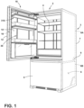
FIG. 1 is a front perspective view of an appliance having a door in an open position with a plurality of bins supported on a support assembly; -
FIG. 2 is a top perspective view of the door ofFIG. 1 as removed from the appliance with a bin assembly coupled thereto; -
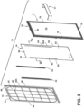
FIG. 3 is an exploded top perspective view of the door ofFIG. 2 ; -
FIG. 4 is a front elevation view of the door ofFIG. 2 ; -
FIG. 5 is a cross-section view of the door ofFIG. 4 taken at line V; -
FIG. 6 is a fragmentary cross-section view of an inner panel of the door ofFIG. 3 taken at line VI; -
FIG. 7 is a fragmentary zoomed in view of the inner panel ofFIG. 6 ; -
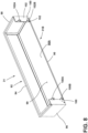
FIG. 8 is a rear perspective view of a bin assembly; -
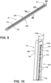
FIG. 9 is a top perspective view of a bracket assembly; -
FIG. 10 is a fragmentary zoomed in view of the bracket assembly ofFIG. 9 ; -
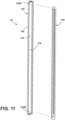
FIG. 11 is an exploded top perspective view of the bracket assembly ofFIG. 9 ; -
FIG. 12 is a fragmentary zoomed in view of the bracket assembly ofFIG. 11 ; -
FIG. 13 is a cross-section view of the bracket assembly ofFIG. 9 taken at line XIII; -
FIG. 14 is a fragmentary cross-section view of the bracket assembly ofFIG. 9 taken at line XIV; -
FIG. 15 is a cross-section view of the bracket assembly ofFIG. 9 taken at line XIII and coupled to an inner panel within a vacuum cavity; -
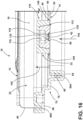
FIG. 16 is a fragmentary cross-section view of the door ofFIG. 2 taken at line XVI; and -
FIG. 17 is a fragmentary cross-section view of the door ofFIG. 2 taken at line XVII. - The components in the figures are not necessarily to scale, emphasis instead being placed upon illustrating the principles described herein.
- The present illustrated embodiments reside primarily in combinations of method steps and apparatus components related to a vacuum insulated door panel configured to support multiple bin assemblies. Accordingly, the apparatus components and method steps have been represented, where appropriate, by conventional symbols in the drawings, showing only those specific details that are pertinent to understanding the embodiments of the present disclosure so as not to obscure the disclosure with details that will be readily apparent to those of ordinary skill in the art having the benefit of the description herein. Further, like numerals in the description and drawings represent like elements.
- For purposes of description herein, the terms "upper," "lower," "right," "left," "rear," "front," "vertical," "horizontal," and derivatives thereof shall relate to the disclosure as oriented in
FIG. 1 . Unless stated otherwise, the term "front" shall refer to the surface of the element closer to an intended viewer, and the term "rear" shall refer to the surface of the element further from the intended viewer. However, it is to be understood that the disclosure may assume various alternative orientations, except where expressly specified to the contrary. It is also to be understood that the specific devices and processes illustrated in the attached drawings, and described in the following specification are simply exemplary embodiments of the inventive concepts defined in the appended claims. Hence, specific dimensions and other physical characteristics relating to the embodiments disclosed herein are not to be considered as limiting, unless the claims expressly state otherwise. - The terms "including," "comprises," "comprising," or any other variation thereof, are intended to cover a non-exclusive inclusion, such that a process, method, article, or apparatus that comprises a list of elements does not include only those elements but may include other elements not expressly listed or inherent to such process, method, article, or apparatus. An element proceeded by "comprises a ... " does not, without more constraints, preclude the existence of additional identical elements in the process, method, article, or apparatus that comprises the element.
- Referring now to
FIG. 1 ,reference numeral 10 generally designates a door for anappliance 2, and more specifically, a vacuum insulated door. Theappliance 2 is illustrated as a refrigerator appliance, however, it is contemplated that thedoor 10 disclosed herein may be used with a variety of appliances, structures, or for insulation purposes other than those associated with a refrigerator appliance. Specifically, the illustratedappliance 2 is a bottom mount refrigerator having thedoor 10 and asecond door 5. Thesecond door 5 is also contemplated to be a vacuum insulated door. Theappliance 2 includes acabinet 3 that defines afirst compartment 4 and asecond compartment 6. The insulateddoor 10 is contemplated to be rotatably coupled to thecabinet 3 for selectively providing access to thefirst compartment 4, which may be a refrigerator compartment. The second insulateddoor 5 is contemplated to be slideably coupled to thecabinet 3 in a drawer-like manner for selectively providing access to thesecond compartment 6, which may be a freezer compartment. Thecabinet 3 of theappliance 2 is an insulated structure having acabinet wrapper 7 with afirst liner 8A and asecond liner 8B positioned therein to define avacuum insulating space 9 therebetween. In non-limiting examples, theappliance 2 can be a bottom mount refrigerator, a bottom mount French door refrigerator, a top mount refrigerator, a side-by-side refrigerator, a four-door French door refrigerator, and/or a five door French door refrigerator, each of which can have one or more insulateddoors 10. - As noted above, the insulated
door 10 is a vacuum insulated panel. As illustrated inFIGS. 1-5 , the insulateddoor 10 includes anouter panel 12 coupled with aninner panel 14 to thereby define avacuum cavity 16 therebetween. Thevacuum cavity 16 defines an insulating cavity for thedoor 10. Theouter panel 12 and theinner panel 14 may alternatively be referred to as a structural wrapper that defines thevacuum cavity 16. Thevacuum cavity 16 of theinsulated door 10 and the insulatingspace 9 of thecabinet 3 typically includes one or more insulation materials disposed therein. The insulation materials may substantially fill thevacuum cavity 16 of thedoor 10, thereby forming a substantially continuous layer between theouter panel 12 and theinner panel 14 of thedoor 10. Similarly, the insulation materials may substantially fill the insulatingspace 9 of the cabinet, thereby forming a substantially continuous layer between thecabinet wrapper 7 and the first andsecond liners - As noted above, the
appliance 2 includes twoinsulated doors second compartments cabinet 3 can each be sealed with aninsulated door outer panel 12 and theinner panel 14 of thedoors compressive force 20, as best shown inFIG. 5 . These materials for theouter panel 12 and theinner panel 14 include, but are not limited to, metals, polymers, metal alloys, combinations thereof, and/or other similar substantially rigid materials that can be used for vacuum insulated structures. - Referring specifically to
FIG. 5 , avacuum 22 is defined within thevacuum cavity 16 of thedoor 10. Thevacuum 22 defines a pressure differential 24 between an exterior 26 or outside environment of theinsulated door 10 and thevacuum cavity 16 disposed within thedoor 10. The pressure differential 24 serves to define the inwardcompressive force 20 that is exerted on both theouter panel 12 and theinner panel 14. The inwardcompressive force 20 tends to bias theouter panel 12 and theinner panel 14 toward one another and toward thevacuum cavity 16. Thevacuum 22 is typically defined by evacuation of theinsulated door 10 at an evacuation port which is later sealed after an evacuation procedure. Over time, gas can infiltrate into thevacuum cavity 16 from an area outside theappliance 2, which can diminish the negative pressure of thevacuum 22. The infiltration of gas is sometimes referred to as gas permeation, which can result in a decrease in thepartial vacuum 22 over time. Gas permeation leads to a reduced vacuum pressure which then leads to reduced insulative properties, so every effort is made to keep the insulting cavity 16 a sealed cavity. This can make the mounting of bin assemblies and storage shelves to thedoor 10 difficult as standard mounting techniques are often not available for a vacuum insulated door. Such techniques not suited for a vacuum insulated door include the mounting of bracket assemblies to theinner panel 14 with fasteners. When mounting such brackets, the fasteners would create holes in theinner panel 14 that can lead to increased gas permeation and possibly total loss of thevacuum 22 within thevacuum cavity 16 of thedoor 10. - Referring again to
FIG. 1 , thedoor 10 is shown having asupport system 30 for supporting a plurality ofbin assemblies 31A. Each bin assembly of the plurality ofbin assemblies 31A is configured to couple to thesupport system 30 at a multitude of vertical locations along thesupport system 30, as further described below. - Referring now to
FIG. 2 , thesupport system 30 of thedoor 10 is shown having asingle bin assembly 31 coupled thereto. As shown inFIG. 2 , thedoor 10 includes anexterior side 10A and aninterior side 10B. Thesupport system 30 includes first and secondupright bracket assemblies inner panel 14 on theinterior side 10B of thedoor 10, as further described below. As further shown inFIG. 2 , theouter panel 12 and theinner panel 14 are interconnected by atrim breaker 70, to form thevacuum cavity 16 therebetween. Thetrim breaker 70 is contemplated to be a polymeric member formed from a suitable material that is substantially impervious to gasses to maintain thevacuum 22 in thevacuum cavity 16 defined between theouter panel 12 and theinner panel 14 as interconnected by thetrim breaker 70. The material composition of thetrim breaker 70 is also contemplated to include a low coefficient of thermal conductivity to reduce or prevent transfer of heat between theouter panel 12 and theinner panel 14. For use with the present concept, thetrim breaker 70 may be formed utilizing a polymeric material in an injection molding process. Other materials suitable to form thetrim breaker 70 may include, but are not limited to, polyureas, polyisocyanurates, polyesters, polyphenols, polyepoxides, thermoplastic elastomers, polycarbonate, and nylon materials. It is further contemplated that thetrim breaker 70 may be overmolded to theouter panel 12 and theinner panel 14 at perimeter edges thereof. In an overmolded construction, thedoor 10 can be a unitary part after thetrim breaker 70 is cast onto the perimeter edges of theouter panel 12 and theinner panel 14. Further, it is contemplated that portions of theinner panel 14 and theouter panel 12 can be coupled to coupling features of thetrim breaker 70 and retained therein using an adhesive as further described below. - Referring now to
FIG. 3 , an exploded view of thedoor 10 is shown, wherein theouter panel 12 andinner panel 14 are exploded away from thetrim breaker 70 that interconnects theouter panel 12 andinner panel 14. As shown inFIG. 3 , theouter panel 12 of thedoor 10 includes a generallyplanar body portion 40 with aninner surface 42 and anouter surface 44. Theouter panel 12 may include anaccess aperture 46 disposed therethrough which can be used to fill thedoor 10 with an insulating material and may also be used as an evacuation port to draw a vacuum on thedoor 10, as described herein. Theouter surface 44 of thebody portion 40 of theouter panel 12 defines theexterior side 10A (FIG. 2 ) of thedoor 10 as assembled. As further shown inFIG. 3 , theouter panel 12 includes asidewall 48 extending outwardly from the generallyplanar body portion 40 of theouter panel 12 along aperiphery 49 thereof. Thesidewall 48 of theouter panel 12 includes afront edge 48A which is configured to be received in a channel of thetrim breaker 70, as further described below with reference toFIG. 16 , to connect theouter panel 12 to thetrim breaker 70. - As further shown in
FIG. 3 , theinner panel 14, like theouter panel 12, includes a generallyplanar body portion 50 having aninner surface 54 and anouter surface 52. Theouter surface 52 of thebody portion 50 of theouter panel 12 defines theinterior side 10B (FIG. 2 ) of thedoor 10 as assembled. Theinner panel 14 further includes asidewall 58 extending outwardly from the generallyplanar body portion 50 of theinner panel 14 along aperiphery 59 thereof. Thesidewall 58 of theinner panel 14 includes afront edge 58A which is configured to be received in a channel of thetrim breaker 70, as further described below with reference toFIG. 16 , to connect theouter panel 12 to thetrim breaker 70. Thesidewalls inner panels entire periphery body portions inner panels FIG. 3 , theinner panel 14 includes first and secondelongate slots body portion 50 ofinner panel 14 in an upright or vertical configuration along theinner panel 14. In assembly, the first and secondelongate slots inner panel 14 are configured to align with the first and secondupright bracket assemblies FIG. 2 to provide access to the same. The first and secondelongate slots inner panel 14. More preferably, the first and secondelongate slots inner panel 14. - As further shown in
FIG. 3 , thetrim breaker 70 is shown having aframe assembly 72 surrounding anopen window 74. Theframe assembly 72 of thetrim breaker 70 is defined by first and secondupright members lower cross members upright members lower cross members trim breaker 70 is contemplated to be a unitary member. - As further shown in
FIG. 3 , thebin assembly 31 and the first and secondupright bracket assemblies inner panel 14. In assembly, the first and secondupright bracket assemblies inner surface 54 of theinner panel 14 in alignment with the first and secondelongate slots inner panel 14, respectively. Thebin assembly 31 includes a number of engagement members that are configured to engage the first and secondupright bracket assemblies bin assembly 31 at a multitude of vertical locations therealong. - Referring now to
FIG. 4 , thedoor 10 ofFIG. 3 is shown in an assembled condition from theinterior side 10B thereof. - Referring now to
FIG. 5 , thetrim breaker 70 is shown having aninner channel 84 and anouter channel 86 spaced-apart from one another. Both theinner channel 84 and theouter channel 86 are forwardly opening channels that are configured to receivefront edges sidewalls outer panel 12 and theinner panel 14, respectively. The interconnection of theinner panel 14 with theinner channel 84 of thetrim breaker 70 and theouter panel 12 with theouter channel 86 of the trim breaker is best shown inFIG. 16 . Theinner channel 84 and theouter channel 86 are contemplated to be continuously disposed around the entirety of theframe assembly 72 of thetrim breaker 70 along the first and secondupright members lower cross members trim breaker 70 and theinner panel 14 andouter panel 12 is complete around theentire frame assembly 72 of thetrim breaker 70 for providing the sealedvacuum cavity 16 therebetween. As further shown inFIG. 5 , theouter channel 86 surrounds theinner channel 84, such that theouter channel 86 is disposed outwardly around theinner channel 84. Specifically, theouter channel 86 is disposed adjacent to a perimeter of thetrim breaker 70, while theinner channel 84 is inset from the perimeter of thetrim breaker 70. Further, theouter channel 86 is disposed in forward position relative to theinner channel 84. Said differently, theinner channel 84 inset from theouter channel 86 relative to theexterior side 10A of thedoor 10. - With the
inner panel 14 and theouter panel 12 coupled to thetrim breaker 70, as shown inFIG. 5 , the sealedvacuum cavity 16 is formed. Thevacuum cavity 16 is configured to receive an insulating material that may be described as a vacuum core material. The vacuum core material may comprise a plurality of individual core panels that are preformed and positioned between theouter panel 12, theinner panel 14 and thetrim breaker 70. Alternatively, the vacuum core material may comprise a silica powder or other suitable loose filler or free-flowing material that is inserted (e.g. poured, blown, compacted) into thevacuum cavity 16, after theouter panel 12 and theinner panel 14 are interconnected by thetrim breaker 70. This free-flowing material can be in the form of various silica-based materials, such as fumed silica, precipitated silica, nano-sized, and/or micro-sized aerogel powder, rice husk ash powder, perlite, glass spheres, hollow glass spheres, cenospheres, diatomaceous earth, combinations thereof, and other similar insulating particulate material. The core material may be inserted into thevacuum cavity 16 through theaccess aperture 46 of theouter panel 12, which opens into thevacuum cavity 16. Thetrim breaker 70 is contemplated to engage theouter panel 12 and theinner panel 14 in a sealed manner so as to create an airtight cavity within thevacuum cavity 16. In this way, thedoor 10 is capable of having thevacuum 22 drawn within thevacuum cavity 16, and maintaining thevacuum 22 given the sealed connections between thetrim breaker 70, theouter panel 12 and theinner panel 14. Further, thevacuum 22 is maintained within thevacuum cavity 16 of thedoor 10 in part by the sheet metal materials of the inner andouter panels trim breaker 70. Thevacuum 22 may have a pressure level of less than 1 atm, about 0.5 atm, about 0.4 atm, about 0.3 atm, about 0.2 atm, about 0.1 atm, about 0.01 atm, or less than about 0.001 atm. - Referring now to
FIG. 6 , the cross-section view of theinner panel 14 shows that the first and secondelongate slots rim portion rim portions elongate slots sidewall 58 of theinner panel 14. This configuration is better shown inFIG. 7 . In assembly, the inwardly extendingrim portions second bracket assemblies FIG. 15 to provide a clean aesthetic to the access point of the first andsecond bracket assemblies FIG. 7 , the firstelongate slot 62 includes awidth 62A that defines a width of the opening of the firstelongate slot 62. The secondelongate slot 64 is also similarly configured with a width of the same size aswidth 62A. As shown inFIG. 7 , the inwardly extendingrim portion 66 of the firstelongate slot 62 culminates in arear edge portion 66A. - Referring now to
FIG. 8 , thebin assembly 31 includes abottom wall 90 with anupper surface 90A. Asidewall 92 extends upwardly from theupper surface 90A of thebottom wall 90 and includes afront portion 94, first andsecond side portions rear portions sidewall 92 includes an overall C-shaped configuration. Together, thebottom wall 90 and thesidewall 92 cooperate with the outer surface of theinner panel 14 to define astorage space 99. Extending outwardly from the first and secondrear portions sidewall 92 are upper andlower hook member lower hook members bin assembly 31 and are configured to removeably couple thebin assembly 31 to the first andsecond bracket assemblies FIGS. 2 and4 . As further shown inFIG. 8 , the upper andlower hook members rear portion 31B of thebin assembly 31. - Referring now to
FIGS. 9-14 , thebracket assembly 32 is shown having afront portion 32A and arear portion 32B.Bracket assembly 32 is identical tobracket assembly 34, such that the description provided herein forbracket assembly 32 will also describebracket assembly 34. Thebracket assembly 32 is an elongate member having ahousing 110 and abracket insert 112 that is received in thehousing 110. Specifically, thehousing 110 includes arear wall 114 with asidewall 116 disposed around a perimeter of therear wall 114 and outwardly extending therefrom to define a forwardly openinginterior cavity 118. Thesidewall 116 includes anouter edge 120 that is defined by a substantially flatouter surface 120A. Theouter edge 120 of thesidewall 116 also surrounds an entirety of theinterior cavity 118. As shown inFIG. 11 , therear wall 114 of thehousing 110 includes upper and lower locating features 122A, 122B in the form of inset receiving divots that are configured to receive reciprocal locating features, such asreciprocal locating feature 123 disposed on thebracket insert 112 and rearwardly extending therefrom, as best shown inFIG. 14 . As shown inFIG. 12 , thehousing 110 includes awidth 110A that is greater than awidth 112A of thebracket insert 112. In this way, thewidth 110A of thehousing 110 can accommodate thewidth 112A of thebracket insert 112, as shown inFIG. 12 . Thewidth 110A of thehousing 110 defines an overall width of thebracket assembly 32, as shown inFIG. 10 . - With further reference to
FIGS. 9-14 , thebracket insert 112 is an elongate member that includes afront wall 124 having anouter surface 124A that is substantially flat. Anopening 126 is centrally disposed along thefront wall 124 and is an elongate opening running substantially the length of thebracket insert 112. Thebracket insert 112 further includes asidewall 128 that extends rearwardly from thefront wall 124 to a substantiallyflat edge portion 128A. Thesidewall 128 surrounds theopening 126 and includes first andsecond sidewall portions cross members 130 that are evenly spaced-apart along a length of theopening 126. Thecross members 130 define a plurality ofcross members 130A (FIG. 12 ) that are positioned across theopening 126. The position of thecross members 130 defines a plurality of receivingapertures 132A (FIG. 10 ), wherein the receivingapertures 132 are evenly spaced-apart along theopening 126 of thebracket insert 112. In assembly, thehook members bin assembly 31 are received through adjacent receivingapertures 132 and engage thecross members 130 of thebracket insert 112 to support thebin assembly 31 therefrom. The first andsecond sidewall portions sidewall 128 are spaced-apart from one another to define a receivingspace 119 disposed therebetween. Each receivingaperture 132 of the plurality of receivingapertures 132A opens into the receivingspace 119. The receivingspace 119 extends inwardly into thevacuum cavity 16 and is configured to receive thehook members FIG. 17 ) when thebin assembly 31 is supported from thebracket assembly 32. The receivingspace 119 is a spatial subset of theinterior cavity 118 in that the receivingspace 119 is defined by the reception of thebracket insert 112 into theinterior cavity 118 ofhousing 110, as best shown inFIG. 13 . - With specific reference to
FIG. 13 , thebracket insert 112 is shown received in theinterior cavity 118 ofhousing 110. With thebracket insert 112 received in theinterior cavity 118 ofhousing 110, theouter surface 120A of thesidewall 116 of thehousing 110 is aligned with theouter surface 124A of thefront wall 124 of thebracket insert 112. Thecross member 130 shown inFIG. 13 includes anouter surface 131 that is inset from theouter surface 124 of thefront wall 124 of thebracket insert 112 to define aninset receiving space 134 disposed along thefront portion 32A of thebracket assembly 32 atopening 126. As further shown inFIG. 13 , the receivingspace 119 extends inwardly or rearwardly into thevacuum cavity 16 in the direction as indicated byarrow 142. Thehook members FIG. 17 ) are also received into the receivingspace 119 in the direction as indicated byarrow 142. - Referring now to
FIG. 15 , thefirst bracket assembly 32 is shown coupled to theinner surface 54 of theinner panel 14. Specifically, theouter surface 120 of thesidewall 116 of thehousing 110 abuts theinner surface 54 of theinner panel 14. Similarly, theouter surface 124 of thesidewall 128 of thebracket insert 112 abuts theinner surface 54 of theinner panel 14. Thehousing 110 and thebracket insert 112 are contemplated to be metal components comprised of a metal material, such as steel, that can be welded to one another to form thebracket assembly 32. As noted above, theinner panel 14 can be comprised of a metal material, such as sheet metal. In this way, at the abutment of theouter surface 120A of thesidewall 116 of thehousing 110 of thebracket assembly 32 and theinner surface 54 of theinner panel 14, acontinuous bead 140 of bonding material can be provided to couple thebracket assembly 32 to the inner surface of theinner panel 14 in a sealed manner. Specifically, thebead 140 is contemplated to be disposed around an entire periphery 33 (FIG. 9 ) of thebracket assembly 32 at theouter edge 120 of thesidewall 116 which is positioned at thefront portion 32A of thebracket assembly 32. By having a sealed engagement between thebracket assembly 32 and theinner panel 14, thevacuum 22 can be maintained within thevacuum cavity 16 between theinner panel 14 and theouter panel 12. Thus, thebracket assembly 32 of the present concept provides for abin support system 30 that is embedded into thedoor panel 10. As further shown inFIG. 15 , theedge portion 66A ofrim portion 66 ofslot 62 is received in theinset receiving space 134 and abuts theouter surface 131 ofcross member 130. In this way, the engagement of theedge portion 66A of therim portion 66 with theouter surfaces 131 of the plurality ofcross members 130A provides a clean aesthetic to the interconnection of thebracket assembly 32 and theinner panel 14, while still providing access to thebracket assembly 32 through theslot 62 defined through and along theinner panel 14. Thecontinuous bead 140 of bonding material may be defined by a weld provided between the metal components of theinner panel 14 and thebracket assembly 32. Further, it is contemplated that thecontinuous bead 140 may be defined by an adhesive that is applied at the location of thecontinuous bead 140 shown inFIG. 15 , or along the substantially flatouter surface 120A of thesidewall 116 of thehousing 110 of thebracket assembly 32. In any of the scenarios described above, thebonding material 140 is contemplated to be a continuous bonding material that provides a continuous seal around the entirety of theperiphery 33 of thebracket assembly 32 providing an airtight engagement between thebracket assembly 32 and theinner panel 14. As used herein, the terms "airtight", "airtight manner", "sealed" and "sealed manner" are used to describe connections and cavities that are suitable for holding a vacuum. - As further shown in
FIG. 15 , and with reference toFIGS. 7 and12 , theoverall width 110A of the bracket assembly 32 (as defined by the housing 110) is greater than thewidth 112A of thebracket insert 112, which is greater than thewidth 62A of theslot 62 of theinner panel 14. In this way, thebracket assembly 32 covers an entirety of theslot 62 when thebracket assembly 32 is coupled to theinner surface 54 of theinner panel 14. By covering an entirety of theslot 62, thebracket assembly 32 ensures that the connection between the bracket assembly and theinner panel 14 is airtight and sealed to help maintain thevacuum 22 within thevacuum cavity 16 of thedoor panel 10. - Referring now to
FIG. 16 ,door panel 10 is shown from a section view that shows the interconnection between thetrim breaker 70 and the outer andinner panels trim breaker 70 and the outer andinner panels vacuum cavity 16 having avacuum 22 drawn thereon. Thefirst bracket assembly 32 is shown coupled to theinner surface 54 of thebody portion 50 of theinner panel 14 with the continuous bead ofbonding material 140 positioned therebetween. The receivingspace 119 defined by the reception of thebracket insert 112 into thehousing 110 is shown rearwardly extending into the vacuum cavity in the direction as indicated byarrow 142. Thus, thefirst bracket assembly 32 is aligned with theelongate slot 62 of theinner panel 14 such that an receivingaperture 132 is made accessible through theinner panel 14 into the receivingspace 119 of thefirst bracket assembly 32. As such, a hook member of thehook members bin assembly 31 can be received through the receivingaperture 132 for engagement with thecross member 130 in the direction as indicated byarrow 144. This engagement is best shown inFIG. 17 , whereinlower hook member 102B of thebin assembly 31 is shown received through theelongate slot 62 of theinner panel 14 and further through the receivingaperture 132 of thefirst bracket assembly 32 into the receivingspace 119. Specifically, thelower hook member 102B includes afirst portion 150 extending outwardly in a rearward direction from therear portion 102 of thesidewall 92 of thebin assembly 31 in a substantially horizontal manner. Thelower hook member 102B further includes asecond portion 152 extending downwardly from thefirst portion 150 in a vertical direction. This configuration is also shown inFIG. 8 and is contemplated to be provided for all thehook members bin assembly 31. Thus, as shown inFIG. 17 , thesecond portion 152 of thehook member 102B is positioned within the receivingspace 119, while thefirst portion 150 abuts thecross member 130 of thebracket insert 112 to support thebin assembly 31 therefrom. - According to various examples, the
insulated door 10 can be used in various appliances that can include, but are not limited to, refrigerators, freezers, coolers, ovens, dishwashers, laundry appliances, and other similar appliances and fixtures within household and commercial settings. - The device disclosed herein is further summarized in the following paragraphs and is further characterized by combinations of any and all of the various aspects described herein.
- According to one aspect of the present disclosure, a door includes an outer panel having a generally planar body portion with inner and outer surfaces and a sidewall with a front edge. The sidewall of the outer panel extends outwardly from the inner surface of the body portion of the outer panel. The door further includes an inner panel having a generally planar body portion with inner and outer surfaces, a sidewall with a front edge, and at least one elongate slot disposed vertically along the generally planar body portion. The sidewall of the inner panel extends outwardly from the inner surface of the body portion of the inner panel. The door further includes a trim breaker interconnecting the outer panel and the inner panel to form a vacuum cavity therebetween. The door further includes at least one bracket assembly positioned within the vacuum cavity of the door and coupled to the inner surface of the inner panel. The at least one bracket assembly is aligned with the at least one elongate slot of the inner panel to provide access to the at least one bracket assembly therethrough.
- According to another aspect of the disclosure, the at least one bracket assembly covers the at least one elongate slot in a sealed manner.
- According to another aspect of the disclosure, the door includes a vacuum formed in the vacuum cavity. The vacuum includes a pressure level of less than 1 atm.
- According to another aspect of the disclosure, the at least one bracket assembly includes a housing having an interior cavity, and a bracket insert received within the interior cavity of the housing and having a rearwardly extending receiving space. The bracket insert includes a plurality of receiving apertures opening into the receiving space.
- According to another aspect of the disclosure, the door includes a bin assembly removeably coupled to the at least one bracket assembly through the at least one elongate slot.
- According to another aspect of the disclosure, the bin assembly includes at least one hook member rearwardly extending therefrom. The at least one hook member is at least partially received in the receiving space of the bracket insert through a receiving aperture of the plurality of receiving apertures.
- According to another aspect of the disclosure, the inner panel and the housing of the at least one bracket assembly are comprised of a metal material. The housing of the at least one bracket assembly is coupled to the inner surface of the inner panel in an airtight manner by a continuous bead of bonding material disposed around a periphery of the housing.
- According to another aspect of the disclosure, the trim breaker further includes an inner channel and an outer channel spaced-apart from one another around the trim breaker. The outer channel is outwardly disposed around the inner channel. The front edge of the inner panel is received in the inner channel of the trim breaker. The front edge of the outer panel is received in the outer channel of the trim breaker.
- According to another aspect of the present disclosure, a vacuum insulated panel includes an outer panel and an inner panel operably coupled to the outer panel to define a vacuum cavity therebetween. The inner panel includes at least one elongate slot disposed therethrough and positioned vertically therealong, and at least one bracket assembly positioned within the vacuum cavity and coupled to an inner surface of the inner panel. The at least one bracket assembly is aligned with the at least one elongate slot of the inner panel to provide access to the at least one bracket assembly therethrough.
- According to another aspect of the disclosure, the vacuum insulated panel includes a vacuum formed in the vacuum cavity. The vacuum includes a pressure level of less than 1 atm.
- According to another aspect of the disclosure, the at least one bracket assembly is coupled to the inner surface of the inner panel in a sealed manner.
- According to another aspect of the disclosure, the at least one bracket assembly includes an opening that opens into a receiving space of the at least one bracket assembly. The at least one bracket assembly further includes a sidewall having first and second sidewall portions spaced-apart from one another to define the receiving space disposed therebetween.
- According to another aspect of the disclosure, the at least one bracket assembly includes a plurality of cross members interconnecting the first and second sidewall portions across the opening to define a plurality of receiving apertures. Each receiving aperture of the plurality of receiving apertures opens into the receiving space.
- According to another aspect of the disclosure, the receiving space of the at least one bracket extends rearwardly into the vacuum cavity.
- According to another aspect of the disclosure, the at least one slot includes a rim portion rearwardly extending therefrom and received in the opening of the at least one bracket assembly.
- According to yet another aspect of the present disclosure, a vacuum insulated panel includes an outer panel and an inner panel operably coupled to the outer panel to define a vacuum cavity therebetween. The inner panel includes a body portion having inner and outer surfaces. The inner panel further includes first and second slots disposed through the body portion that are spaced-apart from one another. A first bracket assembly is operably coupled to the inner surface of the inner panel. The first bracket assembly covers the first slot of the inner panel. A second bracket assembly is operably coupled to the inner surface of the inner panel. The second bracket assembly covers the second slot of the inner panel.
- According to another aspect of the disclosure, the first and second bracket assemblies each include a receiving space and a plurality of receiving apertures opening into the receiving space. The receiving space extends into the vacuum cavity.
- According to another aspect of the disclosure, the vacuum insulated panel includes a bin assembly having first and second hook members that rearwardly extending from the bin assembly. The first and second hook members are received through the receiving apertures of the first and second bracket assemblies, respectively, to removeably couple the bin assembly to the vacuum insulated panel.
- According to another aspect of the disclosure, the first and second bracket assemblies each include a width that is greater than a width of the first and second slots of the inner panel.
- According to another aspect of the disclosure, the inner panel and the first and second bracket assemblies are comprised of a metal material. The first and second bracket assemblies are welded to the inner surface of the inner panel in an airtight manner.
- According to yet another aspect of the present disclosure, a vacuum insulated panel includes an outer panel and an inner panel that are operably coupled to one another to define a vacuum cavity therebetween. The inner panel includes at least one elongate slot disposed therethrough and positioned vertically therealong. At least one bracket assembly is positioned within the vacuum cavity and is coupled to an inner surface of the inner panel. The at least one bracket assembly is aligned with the at least one elongate slot of the inner panel to provide access to the at least one bracket assembly therethrough.
- According to another aspect of the disclosure, a vacuum is formed in the vacuum cavity. The vacuum includes a pressure level of less than 1 atm.
- According to another aspect of the disclosure, the at least one bracket assembly is coupled to the inner surface of the inner panel in a sealed manner.
- According to another aspect of the disclosure, the at least one bracket assembly includes an opening that opens into a receiving space of the at least one bracket assembly. The at least one bracket assembly further includes a sidewall having first and second sidewall portions spaced-apart from one another to define the receiving space disposed therebetween.
- According to another aspect of the disclosure, the at least one bracket assembly includes a plurality of cross members interconnecting the first and second sidewall portions across the opening to define a plurality of receiving apertures. Each receiving aperture of the plurality of receiving apertures opens into the receiving space.
- According to another aspect of the disclosure, the receiving space of the at least one bracket assembly extends rearwardly into the vacuum cavity.
- According to another aspect of the disclosure, the at least one elongate slot includes a rim portion rearwardly extending therefrom and received in the opening of the at least one bracket assembly.
- According to another aspect of the disclosure, the at least one elongate slot of the inner panel includes first and second elongate slots spaced-apart from one another.
- According to another aspect of the disclosure, the at least one bracket assembly includes first and second bracket assemblies. The first bracket assembly is operably coupled to the inner surface of the inner panel. The second bracket assembly is operably coupled to the inner surface of the inner panel.
- According to another aspect of the disclosure, the first bracket assembly covers the first elongate slot of the inner panel. The second bracket assembly covers the second elongate slot of the inner panel.
- According to another aspect of the disclosure, the first and second bracket assemblies each include a receiving space and a plurality of receiving apertures opening into the receiving space. The receiving space extends into the vacuum cavity.
- According to another aspect of the disclosure, a bin assembly includes first and second hook members rearwardly extending therefrom. The first and second hook members are received through receiving apertures of the first and second bracket assemblies, respectively, to removeably couple the bin assembly to the vacuum insulated panel.
- According to another aspect of the disclosure, the first and second bracket assemblies each include a width that is greater than a width of the first and second elongate slots of the inner panel.
- According to another aspect of the disclosure, the inner panel and the first and second bracket assemblies are comprised of a metal material. The first and second bracket assemblies are welded to the inner surface of the inner panel in an airtight manner.
- According to another aspect of the disclosure, the vacuum insulated panel defines an appliance door.
Claims (15)
- A vacuum insulated panel (10), comprising:an outer panel (12);an inner panel (14) operably coupled to the outer panel (12) to define a vacuum cavity (16) therebetween, wherein the inner panel (14) includes at least one elongate slot (62) disposed therethrough and positioned vertically therealong; andat least one bracket assembly (32) positioned within the vacuum cavity (16) and coupled to an inner surface (54) of the inner panel (14), wherein the at least one bracket assembly (32) is aligned with the at least one elongate slot (62) of the inner panel (14) to provide access to the at least one bracket assembly (32) therethrough.
- The vacuum insulated panel (10) of claim 1, including:
a vacuum formed in the vacuum cavity (16), wherein the vacuum includes a pressure level of less than 1 atm. - The vacuum insulated panel (10) of claim 2, wherein the at least one bracket assembly (32) is coupled to the inner surface (54) of the inner panel (14) in a sealed manner.
- The vacuum insulated panel (10) of claim 1, wherein the at least one bracket assembly (32) includes an opening (126) that opens into a receiving space (119) of the at least one bracket assembly (32), and further wherein the at least one bracket assembly (32) further includes a sidewall (128) having first and second sidewall portions (129A, 129B) spaced-apart from one another to define the receiving space (119) disposed therebetween.
- The vacuum insulated panel (10) of claim 4, wherein the at least one bracket assembly (32) includes a plurality of cross members (130) interconnecting the first and second sidewall portions (129A, 129B) across the opening (126) to define a plurality of receiving apertures (132A), wherein each receiving aperture (132) of the plurality of receiving apertures (132A) opens into the receiving space (119).
- The vacuum insulated panel (10) of claim 5, wherein the receiving space (119) of the at least one bracket assembly (32) extends rearwardly into the vacuum cavity (16).
- The vacuum insulated panel (10) of any one of claims 4-6, wherein the at least one elongate slot (62) includes a rim portion (66) rearwardly extending therefrom and received in the opening (126) of the at least one bracket assembly (32).
- The vacuum insulated panel (10) of any one of claims 1-7, wherein the at least one elongate slot (62) of the inner panel (14) includes first and second elongate slots (62, 64) spaced-apart from one another.
- The vacuum insulated panel (10) of claim 8, wherein the at least one bracket assembly (32) includes first and second bracket assemblies (32, 34), wherein the first bracket assembly (32) is operably coupled to the inner surface (54) of the inner panel (14), and further wherein the second bracket assembly (34) is operably coupled to the inner surface (54) of the inner panel (14).
- The vacuum insulated panel (10) of claim 9, wherein the first bracket assembly (32) covers the first elongate slot (62) of the inner panel (14), and further wherein the second bracket assembly (34) covers the second elongate slot (64) of the inner panel (14).
- The vacuum insulated panel (10) of claim 10, wherein the first and second bracket assemblies (32, 34) each include a receiving space (119) and a plurality of receiving apertures (132A) opening into the receiving space (119), and further wherein the receiving space (119) extends into the vacuum cavity (16).
- The vacuum insulated panel (10) of claim 11, including:
a bin assembly (31) having first and second hook members (100A, 102A) rearwardly extending therefrom, wherein the first and second hook members (100A, 102A) are received through receiving apertures (132) of the first and second bracket assemblies (32, 34), respectively, to removeably couple the bin assembly (31) to the vacuum insulated panel (10). - The vacuum insulated panel (10) of any one of claims 9-12, wherein the first and second bracket assemblies (32, 34) each include a width (110A) that is greater than a width (62A) of the first and second elongate slots (62, 64) of the inner panel (14).
- The vacuum insulated panel (10) of any one of claims 9-13, wherein the inner panel (14) and the first and second bracket assemblies (32, 34) are comprised of a metal material, and further wherein the first and second bracket assemblies (32, 34) are welded to the inner surface (54) of the inner panel (14) in an airtight manner.
- The vacuum insulated panel (10) of any one of claims 1-14, wherein the vacuum insulated panel (10) defines an appliance door (10).
Applications Claiming Priority (1)
| Application Number | Priority Date | Filing Date | Title |
|---|---|---|---|
| US18/364,647 US20250044016A1 (en) | 2023-08-03 | 2023-08-03 | Support system for a vacuum insulated panel |
Publications (1)
| Publication Number | Publication Date |
|---|---|
| EP4502511A1 true EP4502511A1 (en) | 2025-02-05 |
Family
ID=92212618
Family Applications (1)
| Application Number | Title | Priority Date | Filing Date |
|---|---|---|---|
| EP24192486.9A Withdrawn EP4502511A1 (en) | 2023-08-03 | 2024-08-02 | Support system for a vacuum insulated panel |
Country Status (2)
| Country | Link |
|---|---|
| US (1) | US20250044016A1 (en) |
| EP (1) | EP4502511A1 (en) |
Families Citing this family (2)
| Publication number | Priority date | Publication date | Assignee | Title |
|---|---|---|---|---|
| KR20240042821A (en) * | 2022-09-26 | 2024-04-02 | 엘지전자 주식회사 | Refrigerator |
| US12535260B2 (en) * | 2023-11-21 | 2026-01-27 | Whirlpool Corporation | Trimbreaker ladder cover |
Citations (3)
| Publication number | Priority date | Publication date | Assignee | Title |
|---|---|---|---|---|
| US9863690B1 (en) * | 2016-11-23 | 2018-01-09 | Bsh Hausgeraete Gmbh | Home appliance door |
| KR20190010383A (en) * | 2017-07-21 | 2019-01-30 | 엘지전자 주식회사 | refrigerator |
| US20230078837A1 (en) * | 2021-09-15 | 2023-03-16 | Whirlpool Corporation | Attachment assembly for an insulated door |
Family Cites Families (19)
| Publication number | Priority date | Publication date | Assignee | Title |
|---|---|---|---|---|
| DE102005021537A1 (en) * | 2005-05-10 | 2006-11-16 | BSH Bosch und Siemens Hausgeräte GmbH | Door for a refrigeration appliance |
| DE102007005951A1 (en) * | 2007-02-06 | 2008-08-07 | BSH Bosch und Siemens Hausgeräte GmbH | Butter compartment for a refrigerator |
| DE102007005949A1 (en) * | 2007-02-06 | 2008-08-07 | BSH Bosch und Siemens Hausgeräte GmbH | Household appliance with carrier system |
| CN102713123B (en) * | 2009-11-20 | 2015-05-06 | 伊莱克斯家用产品有限公司 | Insulated door and method of assembling insulated door |
| KR102025734B1 (en) * | 2012-11-09 | 2019-09-27 | 삼성전자주식회사 | Refrigerator and method of making the inner door thereof |
| TR201408995A2 (en) * | 2014-08-01 | 2016-02-22 | Bsh Ev Aletleri San Ve Tic As | A cooling devi̇ce comprising a support base and a support rail |
| DE112015005844T5 (en) * | 2014-12-29 | 2017-10-12 | BSH Hausgeräte GmbH | Household appliance with a door compartment with a frame holding a shell |
| US9572428B2 (en) * | 2015-03-23 | 2017-02-21 | Whirlpool Corporation | Concealed vertical adjustment mechanism for kitchen appliance storage members |
| KR101701860B1 (en) * | 2015-04-14 | 2017-02-02 | 엘지전자 주식회사 | Refrigerator |
| US11994336B2 (en) * | 2015-12-09 | 2024-05-28 | Whirlpool Corporation | Vacuum insulated structure with thermal bridge breaker with heat loop |
| US11320193B2 (en) * | 2016-07-26 | 2022-05-03 | Whirlpool Corporation | Vacuum insulated structure trim breaker |
| US9879900B1 (en) * | 2016-09-06 | 2018-01-30 | Whirlpool Corporation | Column cabinet construction and method for door construction |
| US11313611B2 (en) * | 2019-05-01 | 2022-04-26 | Whirlpool Corporation | Construction method for vacuum insulated door |
| US10995488B1 (en) * | 2019-11-20 | 2021-05-04 | Whirlpool Corporation | Servicing assembly for an insulated structure |
| US11898791B2 (en) * | 2020-05-08 | 2024-02-13 | Whirlpool Corporation | Appliance door gasket assembly |
| US11340008B1 (en) * | 2021-01-20 | 2022-05-24 | Whirlpool Corporation | Appliance trim breaker assembly |
| US11624547B2 (en) * | 2021-06-14 | 2023-04-11 | Whirlpool Corporation | Bin attachment assembly for a trim breaker |
| US11759010B2 (en) * | 2022-01-28 | 2023-09-19 | Delta Cycle Corporation | Supportive and aesthetically pleasing adjustable shelf system |
| US12031770B2 (en) * | 2022-02-15 | 2024-07-09 | Whirlpool Corporation | Storage assembly for an appliance |
-
2023
- 2023-08-03 US US18/364,647 patent/US20250044016A1/en active Pending
-
2024
- 2024-08-02 EP EP24192486.9A patent/EP4502511A1/en not_active Withdrawn
Patent Citations (3)
| Publication number | Priority date | Publication date | Assignee | Title |
|---|---|---|---|---|
| US9863690B1 (en) * | 2016-11-23 | 2018-01-09 | Bsh Hausgeraete Gmbh | Home appliance door |
| KR20190010383A (en) * | 2017-07-21 | 2019-01-30 | 엘지전자 주식회사 | refrigerator |
| US20230078837A1 (en) * | 2021-09-15 | 2023-03-16 | Whirlpool Corporation | Attachment assembly for an insulated door |
Also Published As
| Publication number | Publication date |
|---|---|
| US20250044016A1 (en) | 2025-02-06 |
Similar Documents
| Publication | Publication Date | Title |
|---|---|---|
| US11971208B2 (en) | Double cabinet vacuum insulated refrigerator with a structural foamed mullion | |
| US20250044016A1 (en) | Support system for a vacuum insulated panel | |
| US12222155B2 (en) | Flexible passthrough insulation for VIS | |
| EP3734165B1 (en) | Vacuum insulated door | |
| US8944541B2 (en) | Vacuum panel cabinet structure for a refrigerator | |
| EP3792574B1 (en) | Appliance mounting assembly | |
| EP3851778A1 (en) | A cabinet of an appliance comprising a reinforcing assembly | |
| US12235038B2 (en) | Trim breaker for a structural cabinet that incorporates a structural glass contact surface | |
| EP3839385A1 (en) | Insulated door assembly | |
| EP3929514B1 (en) | Refrigeration appliance cabinet assembly | |
| EP4198422A1 (en) | Door assembly | |
| EP4184093A1 (en) | Connector assembly for vacuum insulated structures | |
| US12535260B2 (en) | Trimbreaker ladder cover | |
| JP3043200B2 (en) | Cold storage | |
| US20250341359A1 (en) | Trim breaker profile for a vacuum insulated structure | |
| JP7569715B2 (en) | Refrigerator and manufacturing method thereof | |
| JP7674862B2 (en) | How to make a refrigerator | |
| JP7612462B2 (en) | Refrigerator and manufacturing method thereof | |
| JP2020176806A (en) | Insulated door and refrigerator equipped with it | |
| US20240271859A1 (en) | Vacuum insulated structure with thermal bridge breaker with heat loop | |
| WO2019099048A1 (en) | Appliance encapsulation member | |
| JP2000018809A (en) | Storehouse | |
| KR20090041674A (en) | Body Cover for Storage | |
| MXPA98004169A (en) | Refrigerator length |
Legal Events
| Date | Code | Title | Description |
|---|---|---|---|
| PUAI | Public reference made under article 153(3) epc to a published international application that has entered the european phase |
Free format text: ORIGINAL CODE: 0009012 |
|
| STAA | Information on the status of an ep patent application or granted ep patent |
Free format text: STATUS: THE APPLICATION HAS BEEN PUBLISHED |
|
| AK | Designated contracting states |
Kind code of ref document: A1 Designated state(s): AL AT BE BG CH CY CZ DE DK EE ES FI FR GB GR HR HU IE IS IT LI LT LU LV MC ME MK MT NL NO PL PT RO RS SE SI SK SM TR |
|
| STAA | Information on the status of an ep patent application or granted ep patent |
Free format text: STATUS: THE APPLICATION HAS BEEN WITHDRAWN |
|
| 18W | Application withdrawn |
Effective date: 20250410 |