EP4502509A1 - Inner compartment for refrigerator and refrigerator having said compartment - Google Patents
Inner compartment for refrigerator and refrigerator having said compartment Download PDFInfo
- Publication number
- EP4502509A1 EP4502509A1 EP23778110.9A EP23778110A EP4502509A1 EP 4502509 A1 EP4502509 A1 EP 4502509A1 EP 23778110 A EP23778110 A EP 23778110A EP 4502509 A1 EP4502509 A1 EP 4502509A1
- Authority
- EP
- European Patent Office
- Prior art keywords
- cooling zone
- evaporator
- inner liner
- cold storage
- refrigerator
- Prior art date
- Legal status (The legal status is an assumption and is not a legal conclusion. Google has not performed a legal analysis and makes no representation as to the accuracy of the status listed.)
- Pending
Links
Images



Classifications
-
- F—MECHANICAL ENGINEERING; LIGHTING; HEATING; WEAPONS; BLASTING
- F25—REFRIGERATION OR COOLING; COMBINED HEATING AND REFRIGERATION SYSTEMS; HEAT PUMP SYSTEMS; MANUFACTURE OR STORAGE OF ICE; LIQUEFACTION SOLIDIFICATION OF GASES
- F25D—REFRIGERATORS; COLD ROOMS; ICE-BOXES; COOLING OR FREEZING APPARATUS NOT OTHERWISE PROVIDED FOR
- F25D23/00—General constructional features
- F25D23/02—Doors; Covers
- F25D23/04—Doors; Covers with special compartments, e.g. butter conditioners
-
- F—MECHANICAL ENGINEERING; LIGHTING; HEATING; WEAPONS; BLASTING
- F25—REFRIGERATION OR COOLING; COMBINED HEATING AND REFRIGERATION SYSTEMS; HEAT PUMP SYSTEMS; MANUFACTURE OR STORAGE OF ICE; LIQUEFACTION SOLIDIFICATION OF GASES
- F25B—REFRIGERATION MACHINES, PLANTS OR SYSTEMS; COMBINED HEATING AND REFRIGERATION SYSTEMS; HEAT PUMP SYSTEMS
- F25B39/00—Evaporators; Condensers
- F25B39/02—Evaporators
-
- F—MECHANICAL ENGINEERING; LIGHTING; HEATING; WEAPONS; BLASTING
- F25—REFRIGERATION OR COOLING; COMBINED HEATING AND REFRIGERATION SYSTEMS; HEAT PUMP SYSTEMS; MANUFACTURE OR STORAGE OF ICE; LIQUEFACTION SOLIDIFICATION OF GASES
- F25D—REFRIGERATORS; COLD ROOMS; ICE-BOXES; COOLING OR FREEZING APPARATUS NOT OTHERWISE PROVIDED FOR
- F25D11/00—Self-contained movable devices, e.g. domestic refrigerators
- F25D11/02—Self-contained movable devices, e.g. domestic refrigerators with cooling compartments at different temperatures
- F25D11/022—Self-contained movable devices, e.g. domestic refrigerators with cooling compartments at different temperatures with two or more evaporators
-
- F—MECHANICAL ENGINEERING; LIGHTING; HEATING; WEAPONS; BLASTING
- F25—REFRIGERATION OR COOLING; COMBINED HEATING AND REFRIGERATION SYSTEMS; HEAT PUMP SYSTEMS; MANUFACTURE OR STORAGE OF ICE; LIQUEFACTION SOLIDIFICATION OF GASES
- F25D—REFRIGERATORS; COLD ROOMS; ICE-BOXES; COOLING OR FREEZING APPARATUS NOT OTHERWISE PROVIDED FOR
- F25D17/00—Arrangements for circulating cooling fluids; Arrangements for circulating gas, e.g. air, within refrigerated spaces
- F25D17/04—Arrangements for circulating cooling fluids; Arrangements for circulating gas, e.g. air, within refrigerated spaces for circulating air, e.g. by convection
- F25D17/06—Arrangements for circulating cooling fluids; Arrangements for circulating gas, e.g. air, within refrigerated spaces for circulating air, e.g. by convection by forced circulation
- F25D17/062—Arrangements for circulating cooling fluids; Arrangements for circulating gas, e.g. air, within refrigerated spaces for circulating air, e.g. by convection by forced circulation in household refrigerators
- F25D17/065—Arrangements for circulating cooling fluids; Arrangements for circulating gas, e.g. air, within refrigerated spaces for circulating air, e.g. by convection by forced circulation in household refrigerators with compartments at different temperatures
-
- F—MECHANICAL ENGINEERING; LIGHTING; HEATING; WEAPONS; BLASTING
- F25—REFRIGERATION OR COOLING; COMBINED HEATING AND REFRIGERATION SYSTEMS; HEAT PUMP SYSTEMS; MANUFACTURE OR STORAGE OF ICE; LIQUEFACTION SOLIDIFICATION OF GASES
- F25D—REFRIGERATORS; COLD ROOMS; ICE-BOXES; COOLING OR FREEZING APPARATUS NOT OTHERWISE PROVIDED FOR
- F25D23/00—General constructional features
- F25D23/06—Walls
- F25D23/065—Details
- F25D23/066—Liners
-
- F—MECHANICAL ENGINEERING; LIGHTING; HEATING; WEAPONS; BLASTING
- F25—REFRIGERATION OR COOLING; COMBINED HEATING AND REFRIGERATION SYSTEMS; HEAT PUMP SYSTEMS; MANUFACTURE OR STORAGE OF ICE; LIQUEFACTION SOLIDIFICATION OF GASES
- F25B—REFRIGERATION MACHINES, PLANTS OR SYSTEMS; COMBINED HEATING AND REFRIGERATION SYSTEMS; HEAT PUMP SYSTEMS
- F25B5/00—Compression machines, plants or systems, with several evaporator circuits, e.g. for varying refrigerating capacity
-
- F—MECHANICAL ENGINEERING; LIGHTING; HEATING; WEAPONS; BLASTING
- F25—REFRIGERATION OR COOLING; COMBINED HEATING AND REFRIGERATION SYSTEMS; HEAT PUMP SYSTEMS; MANUFACTURE OR STORAGE OF ICE; LIQUEFACTION SOLIDIFICATION OF GASES
- F25C—PRODUCING, WORKING OR HANDLING ICE
- F25C1/00—Producing ice
-
- F—MECHANICAL ENGINEERING; LIGHTING; HEATING; WEAPONS; BLASTING
- F25—REFRIGERATION OR COOLING; COMBINED HEATING AND REFRIGERATION SYSTEMS; HEAT PUMP SYSTEMS; MANUFACTURE OR STORAGE OF ICE; LIQUEFACTION SOLIDIFICATION OF GASES
- F25D—REFRIGERATORS; COLD ROOMS; ICE-BOXES; COOLING OR FREEZING APPARATUS NOT OTHERWISE PROVIDED FOR
- F25D23/00—General constructional features
- F25D23/12—Arrangements of compartments additional to cooling compartments; Combinations of refrigerators with other equipment, e.g. stove
-
- F—MECHANICAL ENGINEERING; LIGHTING; HEATING; WEAPONS; BLASTING
- F25—REFRIGERATION OR COOLING; COMBINED HEATING AND REFRIGERATION SYSTEMS; HEAT PUMP SYSTEMS; MANUFACTURE OR STORAGE OF ICE; LIQUEFACTION SOLIDIFICATION OF GASES
- F25D—REFRIGERATORS; COLD ROOMS; ICE-BOXES; COOLING OR FREEZING APPARATUS NOT OTHERWISE PROVIDED FOR
- F25D2317/00—Details or arrangements for circulating cooling fluids; Details or arrangements for circulating gas, e.g. air, within refrigerated spaces, not provided for in other groups of this subclass
- F25D2317/06—Details or arrangements for circulating cooling fluids; Details or arrangements for circulating gas, e.g. air, within refrigerated spaces, not provided for in other groups of this subclass with forced air circulation
- F25D2317/062—Details or arrangements for circulating cooling fluids; Details or arrangements for circulating gas, e.g. air, within refrigerated spaces, not provided for in other groups of this subclass with forced air circulation along the inside of doors
Definitions
- the present invention relates to refrigeration equipment, particularly to an inner liner for a refrigerator and a refrigerator having the same.
- evaporators are typically required to create different temperature zone environments.
- evaporators need to be installed on the inner liner of the refrigerator.
- one inner liner can usually only accommodate one evaporator, resulting in poor integration.
- inner liners with larger volumes their space cannot be fully utilized.
- One objective of the present invention is to overcome at least one technical deficiency in the prior art and provide an inner liner for a refrigerator and a refrigerator having the same.
- a further objective of the present invention is to provide a dual-evaporator inner liner, improving space utilization of the inner liner and enhancing the integration of the refrigerator.
- an inner liner for a refrigerator wherein, the inner liner comprises a first cooling zone and a second cooling zone, the first cooling zone and the second cooling zone are each configured to install an evaporator.
- the inner liner is a refrigerating compartment liner.
- first cooling zone and the second cooling zone are thermally isolated from each other, and are arranged side by side horizontally on the rear wall of the inner liner.
- the rear wall of the inner liner comprises a protruding annular protrusion on its inner side, thereby forming the second cooling zone within it;
- the protruding annular protrusion is integrally formed with the rear wall of the inner liner; and the protruding annular protrusion is made of thermal insulation material;
- the first cooling zone is arranged on one side of the protruding annular protrusion.
- the upper sections of the first cooling zone and the second cooling zone each form an air circulation zone for installing a fan; and the first cooling zone is configured so that the installed evaporator is positioned below its upper section, and the second cooling zone is configured so that the installed evaporator is positioned below its upper section.
- the refrigerator comprises a first cold storage compartment formed inside the inner liner and a second cold storage compartment located outside the inner liner; and the refrigerator further comprises: a first evaporator, installed in the first cooling zone, configured to supply cold to the first cold storage compartment; and a second evaporator, installed in the second cooling zone, configured to supply cold to the second cold storage compartment.
- the refrigerator further comprising: a first fan, installed in the first cooling zone and positioned above the first evaporator, configured to promote air circulation flowing through the first evaporator, the first air duct, and the first cold storage compartment; and a second fan, installed in the second cooling zone and positioned above the second evaporator, configured to promote air circulation flowing through the second evaporator, the second air duct, and the second cold storage compartment.
- the refrigerator further comprising: a first front panel, arranged at the front of the first cooling zone and the second cooling zone, to separate the first cold storage compartment from the first cooling zone and the second cooling zone; and a second front panel, arranged at the front of the second cooling zone, positioned behind the first front panel, and closing the forward opening of the first cooling zone; and the first front panel and the second front panel each have a thermal insulation layer.
- the inner liner for a refrigerator and the refrigerator having the same provide a dual-evaporator inner liner through rational zoning of the inner liner.
- the inner liner simultaneously defines a first cooling zone and a second cooling zone, with each cooling zone used for installing an evaporator, the space utilization of the inner liner is improved.
- Different evaporators can be simultaneously installed in the same inner liner, which is conducive to enhancing the integration of the refrigerator.
- the refrigerating compartment liner when it is selected as the dual-evaporator inner liner, it can fully utilize its spatial advantages, meeting the space assembly requirements of two cooling zones.
- the layout of the refrigerator's cooling supply structure is also adjusted, which is beneficial for improving the refrigeration performance of the refrigerator and allows other inner liners of the refrigerator to release more storage space.
- the distance between the second cooling zone and the door-mounted ice-making module is shorter. There is no need to arrange excessively long cooling supply pipes between them, which is conducive to simplifying the cold supply structure of the door-mounted ice-making module.
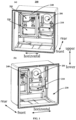
- FIG. 1 is a schematic structural diagram of an inner liner 200 for a refrigerator 10 according to an embodiment of the present invention.
- FIG. 1(a) and (b) illustrate the structure of the inner liner 200 from two different perspectives.
- the inner liner 200 of this embodiment is designed to be assembled into the cabinet of the refrigerator 10, forming the body 110.
- the inner liner 200 comprises a first cooling zone 210 and a second cooling zone 220, each of which is used for installing an evaporator.
- each cooling zone forms an evaporator installation area.
- the inner liner 200 of this embodiment can simultaneously accommodate two evaporators, forming a dual-evaporator inner liner 200.
- the first cooling zone 210 and the second cooling zone 220 can be arranged on any wall of the inner liner 200, such as the rear wall, top wall, bottom wall, or side wall. Of course, depending on layout requirements, the first cooling zone 210 and the second cooling zone 220 can also be arranged on any different walls of the inner liner 200.
- This embodiment provides a dual-evaporator inner liner 200 through rational zoning of the inner liner 200.
- the inner liner 200 simultaneously defines the first cooling zone 210 and the second cooling zone 220, with each cooling zone used for installing an evaporator, the space utilization of the inner liner 200 is improved.
- Different evaporators can be simultaneously installed in the same inner liner 200, which is conducive to enhancing the integration of the refrigerator 10.
- the type of inner liner 200 can be selected according to the actual assembly requirements of the refrigerator 10, such as a refrigerating compartment liner, freezing compartment liner 200, or variable temperature compartment liner 200.
- the inner liner 200 is a refrigerating compartment liner.
- the refrigerating compartment liner is used for assembling the refrigerating evaporator and forming the refrigerating compartment.
- the refrigerating compartment liner comprises a large volume. Due to the large volume of the refrigerating compartment liner, when it is selected as the dual-evaporator inner liner 200, it can fully utilize its spatial advantages, meeting the space assembly requirements of two cooling zones.
- the layout of the refrigerator's 10 cooling supply structure is also adjusted, which is beneficial for improving the refrigeration performance of the refrigerator 10 and allows other inner liners 200 of the refrigerator 10 to release more storage space.
- the refrigerator 10 can allow for the arrangement of more evaporators, thereby improving the temperature control effect of each space and preventing odor mixing.
- the existing technology typically places the refrigerating evaporator in the center of the rear wall of the refrigerating compartment liner. This leads to insufficient utilization of the rear wall space of the refrigerating compartment liner, limits the number of evaporators that can be installed in the refrigerator 10, and results in crowded space in other inner liners 200, unable to effectively release storage space.
- the inventor of present application creatively sets up the first cooling zone 210 and the second cooling zone 220 on the refrigerating compartment liner of the refrigerator 10, breaking through the constraints of existing technology. This provides a new approach for the rational layout of evaporators in multi-system refrigerators 10, while also solving multiple technical problems such as complex cooling circuit structures, achieving multiple benefits at once.
- the refrigerating evaporator used to supply cooling to the refrigerating compartment can be installed in either the first cooling zone 210 or the second cooling zone 220, while the other cooling zone can be used to install other evaporators and use that evaporator to supply cooling to spaces outside the refrigerating compartment.
- the inner liner 200 that can simultaneously accommodate two evaporators is not limited to the refrigerating compartment liner.
- the first cooling zone 210 forms a refrigerating cooling zone for installing the refrigerating evaporator.
- the second cooling zone 220 forms an ice-making cooling zone for installing an ice-making evaporator, or forms a variable temperature cooling zone for installing a variable temperature evaporator.
- the distance between the second cooling zone 220 and the door-mounted ice-making module is shorter. There is no need to arrange excessively long cooling supply pipes between them, which is conducive to simplifying the cold supply structure of the door-mounted ice-making module, improving cooling efficiency, reducing or avoiding odor mixing, and achieving "clean ice”.
- the refrigerator 10 can be equipped with a separate variable temperature evaporator for the variable temperature compartment, which is beneficial for improving the temperature control effect of the variable temperature compartment.
- the second cooling zone 220 can also form a freezing cooling zone for installing a freezing evaporator.
- a freezing evaporator needs to be installed inside the freezing compartment liner, thereby fully releasing the storage space of the freezing compartment.
- the first cooling zone 210 and the second cooling zone 220 are thermally isolated from each other and arranged side by side horizontally on the rear wall of the inner liner 200.
- thermal insulation materials can be used between the first cooling zone 210 and the second cooling zone 220 to prevent heat exchange and avoid confusion in the cooling process.
- Arranging the first cooling zone 210 and the second cooling zone 220 side by side horizontally allows the upper space of the two cooling zones to be left vacant, so that respective air delivery mechanisms or other components can be arranged in the vacant space, further improving space utilization.
- positions such as “horizontal”, “vertical”, “front”, “rear”, “inner”, “outer”, “upper”, and “lower” are all relative to the actual use state of the inner liner 200.
- the actual use state of the inner liner 200 refers to the state when the inner liner 200 is assembled into the cabinet to form the body 110.
- first cooling zone 210 and the second cooling zone 220 can also be arranged side by side vertically, but are not limited to this.
- the inner side of the rear wall of the inner liner 200 comprises a protruding annular protrusion 240, thereby forming the second cooling zone 220 within it.
- the protruding annular protrusion 240 extends (or protrudes) from a specific annular area of the rear wall of the inner liner 200 towards the inside of the inner liner 200, so that the second cooling zone 220 is defined within the protruding annular protrusion 240 and isolated from the second cooling zone 220 located outside the protruding annular protrusion 240.
- the protruding annular protrusion 240 is made of thermal insulation material, and the first cooling zone 210 is arranged on one side of the protruding annular protrusion 240. This allows the protruding annular protrusion 240 to achieve thermal isolation between the second cooling zone 220 and the first cooling zone 210 on the basis of physical isolation of the second cooling zone 220.
- the protruding annular protrusion 240 can be set on one horizontal side (e.g., the left side) of the rear wall of the inner liner 200, and the first cooling zone 210 can be set on the other horizontal side (e.g., the right side) of the rear wall of the inner liner 200, so that the first cooling zone 210 and the second cooling zone 220 are arranged side by side horizontally.
- the protruding annular protrusion 240 is integrally formed with the rear wall of the inner liner 200, making the connection between the protruding annular protrusion 240 and the rear wall of the inner liner 200 seamless, which is beneficial for improving the thermal insulation effect of the second cooling zone 220.
- the first cooling zone 210 is configured so that the installed evaporator is positioned below its upper section
- the second cooling zone 220 is configured so that the installed evaporator is positioned below its upper section.
- the lower section of the cooling zone, located below the upper section, is used for installing the evaporator
- each air circulation zone 201 is located above the evaporator installation area of its respective cooling zone.
- each cooling zone When fans are installed in the upper sections of the cooling zones, under the driving action of the fans, each cooling zone can circulate air with its corresponding cold storage area, allowing the cold storage area to receive cooling from the corresponding cooling zone, thus achieving temperature control.
- the first cooling zone 210 can be offset to one side of the rear wall of the inner liner 200, while the second cooling zone 220 can be offset to the other side of the rear wall of the inner liner 200.
- offset means that the first cooling zone 210 is set off-center from the rear wall of the inner liner 200, which can be offset horizontally or vertically relative to the inner liner 200.
- the evaporator is usually set in the center of the rear wall of the inner liner 200, which leads to insufficient utilization of the rear wall space of the inner liner 200 and limits the number of evaporators that can be installed in the refrigerator 10.
- the inventor of present application creatively sets up an offset first cooling zone 210 on the inner liner 200 of the refrigerator 10, which can serve as an avoidance, providing sufficient installation space around the first cooling zone 210 for arranging the second cooling zone 220 or installing other components. This breaks through the constraints of existing technology, providing a new approach for the rational use of space within the limited volume of the refrigerator 10.
- the first cooling zone 210 is horizontally offset to one side of the vertical centerline of the rear wall of the inner liner 200. This arrangement allows the space on one horizontal side of the first cooling zone 210 to be left vacant. When the second cooling zone 220 is assembled in this vacant space, it allows the upper space of the first cooling zone 210 to be left empty, so that air delivery mechanisms or other components can be arranged in the vacant space, further improving space utilization.
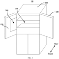
- FIG. 2 is a schematic structural diagram of a refrigerator 10 according to an embodiment of the present invention.
- the refrigerator 10 can generally include an inner liner 200 as described in any of the above embodiments.
- the inner liner 200 comprises a first cooling zone 210 and a second cooling zone 220, with the first cooling zone 210 and the second cooling zone 220 each used for installing an evaporator.
- the refrigerator 10 comprises a first cold storage area 230 formed inside the inner liner 200 and a second cold storage area 310 located outside the inner liner 200.
- first cold storage area 230 can refer to the storage compartment located in front of the first cooling zone 210 and the second cooling zone 220.
- the second cold storage area 310 can refer to storage space defined by other inner liners, or it can refer to other low-temperature spaces formed within the refrigerator 10, such as an ice-making area.
- the first cold storage area 230 can be the refrigerating compartment.
- the second cold storage area 310 can be a low-temperature space set adjacent to the second cooling zone 220, which can simplify the cold supply structure between the second cooling zone 220 and the second cold storage area 310.
- the refrigerating compartment liner of the refrigerator 10 can allow for the arrangement of additional dedicated evaporators, improving the refrigeration performance of the refrigerator 10 and increasing the space utilization of the refrigerating compartment liner.
- FIG. 3 is a schematic front view of a partial structure of the refrigerator 10 according to an embodiment of the present invention.
- the FIG. omits the cabinet 110 and door 120 of the refrigerator 10, and shows the assembly structure of the first cooling zone 210 and the second cooling zone 220 of the inner liner 200.
- the refrigerator 10 also includes a first evaporator 410 and a second evaporator 420.
- the first evaporator 410 is set in the first cooling zone 210 and configured to supply cooling to the first cold storage area 230.
- the second evaporator 420 is set in the second cooling zone 220 and configured to supply cooling to the second cold storage area 310.
- the first evaporator 410 can be a refrigerating evaporator
- the second evaporator 420 can be an ice-making evaporator.
- the refrigerator 10 also includes a door 120.
- the second cold storage area 310 can be the ice-making area of the door-mounted ice-making module set on the door 120, configured to receive cooling provided by the second evaporator 420 and make ice.
- the first evaporator 410 can be a refrigerating evaporator, while the second evaporator 420 can be changed to a variable temperature evaporator.
- the refrigerator 10 can also include another inner liner, and the second cold storage area 310 can be a variable temperature compartment set in that other inner liner.
- the refrigerator 10 also includes a first air duct 510 and a second air duct 520, used for guiding cooling air flow and return air flow respectively.
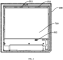
- FIG. 4 is a schematic front view of a partial structure of the refrigerator 10 according to another embodiment of the present invention
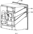
- FIG. 5 is a schematic structural view of a partial structure of the refrigerator 10 according to an embodiment of the present invention.
- These figures omit the cabinet 110 and door 120 of the refrigerator 10, and illustrate the first air duct 510 and the second air duct 520 respectively.
- FIG. 5 shows a rear view schematic diagram of the inner liner 200 assembled with the second air duct 520.
- the first air duct 510 connects between the first cooling zone 210 and the first cold storage area 230, configured to guide the cooling air flow passing through the first evaporator 410 to the first cold storage area 230, and guide the return air flow passing through the first cold storage area 230 to the first cooling zone 210.
- the second air duct 520 connects between the second cooling zone 220 and the second cold storage area 310, configured to guide the cooling air flow passing through the second evaporator 420 to the second cold storage area 310, and guide the return air flow passing through the second cold storage area 310 to the second cooling zone 220.
- the first air duct 510 and the second air duct 520 can each include a supply air duct and a return air duct, where the supply air duct is used for guiding cooling air flow, and the return air duct is used for guiding return air flow.
- each cold storage area can receive specific cooling air flow according to its own temperature settings, achieving temperature control.
- the refrigerator 10 also includes a first fan 610 and a second fan 620.
- the first fan 610 is set in the first cooling zone 210 and positioned above the first evaporator 410, configured to promote air circulation flowing through the first evaporator 410, the first air duct 510, and the first cold storage area 230.
- the second fan 620 is set in the second cooling zone 220 and positioned above the second evaporator 420, configured to promote air circulation flowing through the second evaporator 420, the second air duct 520, and the second cold storage area 310.
- the first fan 610 can be set in the air circulation zone 201 of the first cooling zone 210
- the second fan 620 can be set in the air circulation zone 201 of the second cooling zone 220.
- the cooling air flow can flow out from the top of the evaporator in its cooling zone, and the return air flow can pass through the bottom section of the evaporator and undergo heat exchange when passing through the evaporator again to form cooling air flow, thus achieving circulation.
- FIG. 6 is a schematic front view of a partial structure of the refrigerator 10 according to yet another embodiment of the present invention, with the first front panel 710 omitted in the figure.
- thermal insulation layer to separate the cooling zones and the first cold storage area 230 can prevent heat transfer between the cooling zones and the first cold storage area 230, ensuring that the first cold storage area 230 can only receive cooling from the corresponding air ducts, avoiding ineffective temperature control.
- the first front panel 710 is set at the front of the first cooling zone 210 and the second cooling zone 220, to separate the first cold storage area 230 from the first cooling zone 210 and the second cooling zone 220.
- the first front panel 710 divides the internal space of the inner liner 200 into the front-arranged first cold storage area 230 and the rear-arranged cooling zones.
- the first cold storage area 230 forms the refrigerating compartment, while the cooling zones consist of the horizontally arranged first cooling zone 210 and second cooling zone 220.
- the second front panel 720 is set at the front of the second cooling zone, positioned behind the first front panel 710, and closes the forward opening of the first cooling zone.
- the front side of the second cooling zone 220 comprises the second front panel 720 and the first front panel 710 layered, forming a double-layer thermal insulation, which enhances the insulation effect, reducing or avoiding adverse effects on temperature control of the first cold storage area 230 caused by the additionally installed second evaporator 420.
- the first air duct 510 forms a first air supply outlet 511 and a first air return inlet 512.
- the second air duct 520 forms a second air supply outlet 521 and a second air return inlet 522.
- the first front panel 710 comprises openings for the first air supply outlet 511 and the first air return inlet 512 connecting to the first cooling zone 210, forming the first air duct 510.
- the surrounding wall of the second cooling zone 220 can have openings for the second air supply outlet 521 and the second air return inlet 522 connecting to the second cooling zone 220, forming the second air duct 520.
- the first air supply outlet 511 can be located in the upper section of the first front panel 710, and the first air return inlet 512 can be located in the lower section of the first front panel 710. This allows the cooling air flow passing through the first evaporator 410 to flow upward under the driving action of the fan, and enter the first cold storage area 230 through the first air supply outlet 511.
- the return air flow passing through the first cold storage area 230 can enter the bottom of the first evaporator 410 through the first air return inlet 512, and pass through the first evaporator 410 again for heat exchange.
- first air supply outlets 511 there can be multiple first air supply outlets 511, distributed at intervals along the upper section of the first front panel 710, so that the first air supply outlets 511 are arranged along the width direction of the first cold storage area 230, which is beneficial for improving the uniformity of air supply in the first cold storage area 230.
- FIG. 7 is a schematic structural diagram of a partial structure of the refrigerator 10 according to an embodiment of the present invention. Compared with FIG. 6 , FIG. 7 omits part of the second air duct 520 and exposes the second air supply outlet 521 and the second air return inlet 522.
- the second air supply outlet 521 can be located in the upper section of the side wall of the second cooling zone 220 that is away from the first cooling zone 210, and the second air return inlet 522 can be located in the lower section of the side wall of the second cooling zone 220 that is away from the first cooling zone 210.
- the side wall of the inner liner 200 can have a third air supply outlet and a third air return inlet opened to connect with the air inlet and outlet of the ice-making area of the door-mounted ice-making module respectively.
- the air supply section of the second air duct 520 can extend from the second air supply outlet 521 along the outer surface of the inner liner 200 wall to the third air supply outlet, and the air return section of the second air duct 520 can extend from the second air return inlet 522 along the outer surface of the inner liner 200 wall to the third air return inlet. This allows the cooling air flow passing through the second evaporator 420 to flow upward under the driving action of the fan, and enter the ice-making area of the door-mounted ice-making module through the air supply section of the second air duct 520.
- the return air flow passing through the ice-making area of the door-mounted ice-making module can enter the bottom of the second evaporator 420 through the air return section of the second air duct 520, and pass through the second evaporator 420 again for heat exchange.
- defrosting heating components for defrosting can be installed on the first evaporator 410 and the second evaporator 420 respectively, allowing them to defrost independently.
Landscapes
- Engineering & Computer Science (AREA)
- Physics & Mathematics (AREA)
- Mechanical Engineering (AREA)
- Thermal Sciences (AREA)
- General Engineering & Computer Science (AREA)
- Chemical & Material Sciences (AREA)
- Combustion & Propulsion (AREA)
- Cold Air Circulating Systems And Constructional Details In Refrigerators (AREA)
- Devices That Are Associated With Refrigeration Equipment (AREA)
Abstract
Description
- The present invention relates to refrigeration equipment, particularly to an inner liner for a refrigerator and a refrigerator having the same.
- For multi-system refrigerators, such as dual-system or triple-system refrigerators, multiple evaporators are typically required to create different temperature zone environments. Generally, evaporators need to be installed on the inner liner of the refrigerator. In existing refrigerators, one inner liner can usually only accommodate one evaporator, resulting in poor integration. For inner liners with larger volumes, their space cannot be fully utilized.
- The above information disclosed in this background section is only for enhancing the understanding of the background of the present application and therefore may contain information that does not constitute prior art known to those skilled in the art.
- One objective of the present invention is to overcome at least one technical deficiency in the prior art and provide an inner liner for a refrigerator and a refrigerator having the same.
- A further objective of the present invention is to provide a dual-evaporator inner liner, improving space utilization of the inner liner and enhancing the integration of the refrigerator.
- Another further objective of the present invention is to fully leverage the spatial advantages of the refrigerating compartment liner, improving the refrigeration performance of the refrigerator.
- Yet another further objective of the present invention is to simplify the cold supply structure of the door-mounted ice-making module.
- According to an aspect of the present invention, there is provided an inner liner for a refrigerator, wherein, the inner liner comprises a first cooling zone and a second cooling zone, the first cooling zone and the second cooling zone are each configured to install an evaporator.
- Optionally, wherein the inner liner is a refrigerating compartment liner.
- Optionally, wherein the first cooling zone is formed as a refrigerating cooling zone for installing a refrigerating evaporator; and the second cooling zone is formed as an ice-making cooling zone for installing an ice-making evaporator, or formed as a variable temperature cooling zone for installing a variable temperature evaporator.
- Optionally, wherein the first cooling zone and the second cooling zone are thermally isolated from each other, and are arranged side by side horizontally on the rear wall of the inner liner.
- Optionally, wherein the rear wall of the inner liner comprises a protruding annular protrusion on its inner side, thereby forming the second cooling zone within it; the protruding annular protrusion is integrally formed with the rear wall of the inner liner; and the protruding annular protrusion is made of thermal insulation material; the first cooling zone is arranged on one side of the protruding annular protrusion.
- Optionally, wherein the upper sections of the first cooling zone and the second cooling zone each form an air circulation zone for installing a fan; and the first cooling zone is configured so that the installed evaporator is positioned below its upper section, and the second cooling zone is configured so that the installed evaporator is positioned below its upper section.
- According to another aspect of the present invention, there is also provided a refrigerator, wherein, the refrigerator comprising: an inner liner, the inner liner comprises a first cooling zone and a second cooling zone, the first cooling zone and the second cooling zone are each configured to install an evaporator.
- Optionally, wherein the refrigerator comprises a first cold storage compartment formed inside the inner liner and a second cold storage compartment located outside the inner liner; and the refrigerator further comprises: a first evaporator, installed in the first cooling zone, configured to supply cold to the first cold storage compartment; and a second evaporator, installed in the second cooling zone, configured to supply cold to the second cold storage compartment.
- Optionally, wherein the first evaporator is a refrigerating evaporator; the second evaporator is an ice-making evaporator; the refrigerator further comprises a door; and the second cold storage compartment is an ice-making area set in the door, configured to receive cold supplied by the second evaporator and make ice.
- Optionally, wherein, the refrigerator further comprising: a first air duct, connecting between the first cooling zone and the first cold storage compartment, configured to guide the cooling air flow passing through the first evaporator to the first cold storage compartment, and guide the return air flow passing through the first cold storage compartment to the first cooling zone; and a second air duct, connecting between the second cooling zone and the second cold storage compartment, configured to guide the cooling air flow passing through the second evaporator to the second cold storage compartment, and guide the return air flow passing through the second cold storage compartment to the second cooling zone.
- Optionally, wherein, the refrigerator further comprising: a first fan, installed in the first cooling zone and positioned above the first evaporator, configured to promote air circulation flowing through the first evaporator, the first air duct, and the first cold storage compartment; and a second fan, installed in the second cooling zone and positioned above the second evaporator, configured to promote air circulation flowing through the second evaporator, the second air duct, and the second cold storage compartment.
- Optionally, wherein, the refrigerator further comprising: a first front panel, arranged at the front of the first cooling zone and the second cooling zone, to separate the first cold storage compartment from the first cooling zone and the second cooling zone; and a second front panel, arranged at the front of the second cooling zone, positioned behind the first front panel, and closing the forward opening of the first cooling zone; and the first front panel and the second front panel each have a thermal insulation layer.
- The inner liner for a refrigerator and the refrigerator having the same according to the present invention provide a dual-evaporator inner liner through rational zoning of the inner liner. As the inner liner simultaneously defines a first cooling zone and a second cooling zone, with each cooling zone used for installing an evaporator, the space utilization of the inner liner is improved. Different evaporators can be simultaneously installed in the same inner liner, which is conducive to enhancing the integration of the refrigerator.
- Furthermore, due to the large volume of the refrigerating compartment liner, when it is selected as the dual-evaporator inner liner, it can fully utilize its spatial advantages, meeting the space assembly requirements of two cooling zones. The layout of the refrigerator's cooling supply structure is also adjusted, which is beneficial for improving the refrigeration performance of the refrigerator and allows other inner liners of the refrigerator to release more storage space.
- Moreover, when the first cooling zone forms a refrigerating cooling zone for installing a refrigerating evaporator, and the second cooling zone forms an ice-making cooling zone for installing an ice-making evaporator, the distance between the second cooling zone and the door-mounted ice-making module is shorter. There is no need to arrange excessively long cooling supply pipes between them, which is conducive to simplifying the cold supply structure of the door-mounted ice-making module.
- According to the detailed description of specific embodiments of the present invention in conjunction with the accompanying drawings below, those skilled in the art will have a better understanding of the above and other objectives, advantages, and features of the present invention.
- Some specific embodiments of the present invention will be described in detail below with reference to the accompanying drawings in an exemplary rather than limiting manner. The same reference numerals in the drawings indicate the same or similar components or parts. Those skilled in the art should understand that these drawings are not necessarily drawn to scale. In the drawings:
-
FIG. 1 is a schematic structural diagram of an inner liner for a refrigerator according to an embodiment of the present invention; -
FIG. 2 is a schematic structural diagram of a refrigerator according to an embodiment of the present invention; -
FIG. 3 is a schematic front view of a partial structure of a refrigerator according to an embodiment of the present invention; -
FIG. 4 is a schematic front view of a partial structure of a refrigerator according to another embodiment of the present invention; -
FIG. 5 is a schematic structural diagram of a partial structure of a refrigerator according to an embodiment of the present invention; -
FIG. 6 is a schematic front view of a partial structure of a refrigerator according to yet another embodiment of the present invention; -
FIG. 7 is a schematic structural diagram of a partial structure of a refrigerator according to an embodiment of the present invention. -
FIG. 1 is a schematic structural diagram of aninner liner 200 for arefrigerator 10 according to an embodiment of the present invention.FIG. 1(a) and (b) illustrate the structure of theinner liner 200 from two different perspectives. Theinner liner 200 of this embodiment is designed to be assembled into the cabinet of therefrigerator 10, forming thebody 110. - The
inner liner 200 comprises afirst cooling zone 210 and asecond cooling zone 220, each of which is used for installing an evaporator. In other words, each cooling zone forms an evaporator installation area. Theinner liner 200 of this embodiment can simultaneously accommodate two evaporators, forming a dual-evaporatorinner liner 200. - The
first cooling zone 210 and thesecond cooling zone 220 can be arranged on any wall of theinner liner 200, such as the rear wall, top wall, bottom wall, or side wall. Of course, depending on layout requirements, thefirst cooling zone 210 and thesecond cooling zone 220 can also be arranged on any different walls of theinner liner 200. - This embodiment provides a dual-evaporator
inner liner 200 through rational zoning of theinner liner 200. As theinner liner 200 simultaneously defines thefirst cooling zone 210 and thesecond cooling zone 220, with each cooling zone used for installing an evaporator, the space utilization of theinner liner 200 is improved. Different evaporators can be simultaneously installed in the sameinner liner 200, which is conducive to enhancing the integration of therefrigerator 10. - The type of
inner liner 200 can be selected according to the actual assembly requirements of therefrigerator 10, such as a refrigerating compartment liner,freezing compartment liner 200, or variabletemperature compartment liner 200. In some preferred embodiments, theinner liner 200 is a refrigerating compartment liner. The refrigerating compartment liner is used for assembling the refrigerating evaporator and forming the refrigerating compartment. - For
most refrigerators 10, such as T-shaped refrigerators 10, the refrigerating compartment liner comprises a large volume. Due to the large volume of the refrigerating compartment liner, when it is selected as the dual-evaporatorinner liner 200, it can fully utilize its spatial advantages, meeting the space assembly requirements of two cooling zones. The layout of the refrigerator's 10 cooling supply structure is also adjusted, which is beneficial for improving the refrigeration performance of therefrigerator 10 and allows otherinner liners 200 of therefrigerator 10 to release more storage space. - Adopting the above solution, when it is necessary to provide cooling to different spaces, the
refrigerator 10 can allow for the arrangement of more evaporators, thereby improving the temperature control effect of each space and preventing odor mixing. - It should be emphasized that, regarding the layout of evaporators, the existing technology typically places the refrigerating evaporator in the center of the rear wall of the refrigerating compartment liner. This leads to insufficient utilization of the rear wall space of the refrigerating compartment liner, limits the number of evaporators that can be installed in the
refrigerator 10, and results in crowded space in otherinner liners 200, unable to effectively release storage space. The inventor of present application creatively sets up thefirst cooling zone 210 and thesecond cooling zone 220 on the refrigerating compartment liner of therefrigerator 10, breaking through the constraints of existing technology. This provides a new approach for the rational layout of evaporators inmulti-system refrigerators 10, while also solving multiple technical problems such as complex cooling circuit structures, achieving multiple benefits at once. - The refrigerating evaporator used to supply cooling to the refrigerating compartment can be installed in either the
first cooling zone 210 or thesecond cooling zone 220, while the other cooling zone can be used to install other evaporators and use that evaporator to supply cooling to spaces outside the refrigerating compartment. Of course, in therefrigerator 10, theinner liner 200 that can simultaneously accommodate two evaporators is not limited to the refrigerating compartment liner. - In some optional embodiments, the
first cooling zone 210 forms a refrigerating cooling zone for installing the refrigerating evaporator. Thesecond cooling zone 220 forms an ice-making cooling zone for installing an ice-making evaporator, or forms a variable temperature cooling zone for installing a variable temperature evaporator. - In existing
refrigerators 10 with door-mounted ice-making modules, there is no separate cooling system on thedoor 120, and it is necessary to use the freezing compartment's cooling system to supply cooling to the door-mounted ice-making module. Due to the long distance between the freezing compartment's cooling system and the door-mounted ice-making module, a complex cooling supply structure needs to be arranged between them, resulting in high manufacturing costs, low cooling efficiency, and easy odor mixing. - When the
first cooling zone 210 forms a refrigerating cooling zone for installing the refrigerating evaporator, and thesecond cooling zone 220 forms an ice-making cooling zone for installing the ice-making evaporator, the distance between thesecond cooling zone 220 and the door-mounted ice-making module is shorter. There is no need to arrange excessively long cooling supply pipes between them, which is conducive to simplifying the cold supply structure of the door-mounted ice-making module, improving cooling efficiency, reducing or avoiding odor mixing, and achieving "clean ice". - When the
first cooling zone 210 forms a refrigerating cooling zone for installing the refrigerating evaporator, and thesecond cooling zone 220 forms a variable temperature cooling zone for installing the variable temperature evaporator, therefrigerator 10 can be equipped with a separate variable temperature evaporator for the variable temperature compartment, which is beneficial for improving the temperature control effect of the variable temperature compartment. - Of course, in some embodiments, the
second cooling zone 220 can also form a freezing cooling zone for installing a freezing evaporator. In this case, no freezing evaporator needs to be installed inside the freezing compartment liner, thereby fully releasing the storage space of the freezing compartment. - In some optional embodiments, the
first cooling zone 210 and thesecond cooling zone 220 are thermally isolated from each other and arranged side by side horizontally on the rear wall of theinner liner 200. For example, thermal insulation materials can be used between thefirst cooling zone 210 and thesecond cooling zone 220 to prevent heat exchange and avoid confusion in the cooling process. - Arranging the
first cooling zone 210 and thesecond cooling zone 220 side by side horizontally allows the upper space of the two cooling zones to be left vacant, so that respective air delivery mechanisms or other components can be arranged in the vacant space, further improving space utilization. - The terms indicating positions such as "horizontal", "vertical", "front", "rear", "inner", "outer", "upper", and "lower" are all relative to the actual use state of the
inner liner 200. The actual use state of theinner liner 200 refers to the state when theinner liner 200 is assembled into the cabinet to form thebody 110. - Of course, the
first cooling zone 210 and thesecond cooling zone 220 can also be arranged side by side vertically, but are not limited to this. - In some optional embodiments, the inner side of the rear wall of the
inner liner 200 comprises a protrudingannular protrusion 240, thereby forming thesecond cooling zone 220 within it. The protrudingannular protrusion 240 extends (or protrudes) from a specific annular area of the rear wall of theinner liner 200 towards the inside of theinner liner 200, so that thesecond cooling zone 220 is defined within the protrudingannular protrusion 240 and isolated from thesecond cooling zone 220 located outside the protrudingannular protrusion 240. - The protruding
annular protrusion 240 is made of thermal insulation material, and thefirst cooling zone 210 is arranged on one side of the protrudingannular protrusion 240. This allows the protrudingannular protrusion 240 to achieve thermal isolation between thesecond cooling zone 220 and thefirst cooling zone 210 on the basis of physical isolation of thesecond cooling zone 220. For example, the protrudingannular protrusion 240 can be set on one horizontal side (e.g., the left side) of the rear wall of theinner liner 200, and thefirst cooling zone 210 can be set on the other horizontal side (e.g., the right side) of the rear wall of theinner liner 200, so that thefirst cooling zone 210 and thesecond cooling zone 220 are arranged side by side horizontally. - The protruding
annular protrusion 240 is integrally formed with the rear wall of theinner liner 200, making the connection between the protrudingannular protrusion 240 and the rear wall of theinner liner 200 seamless, which is beneficial for improving the thermal insulation effect of thesecond cooling zone 220. - In some optional embodiments, the upper sections of the
first cooling zone 210 and thesecond cooling zone 220 each form anair circulation zone 201 for installing fans. That is, each cooling zone also provides space for installing fans. The upper section can refer to the upper space of each cooling zone. - The
first cooling zone 210 is configured so that the installed evaporator is positioned below its upper section, and thesecond cooling zone 220 is configured so that the installed evaporator is positioned below its upper section. In other words, the lower section of the cooling zone, located below the upper section, is used for installing the evaporator, and eachair circulation zone 201 is located above the evaporator installation area of its respective cooling zone. - When fans are installed in the upper sections of the cooling zones, under the driving action of the fans, each cooling zone can circulate air with its corresponding cold storage area, allowing the cold storage area to receive cooling from the corresponding cooling zone, thus achieving temperature control.
- In some embodiments, the
first cooling zone 210 can be offset to one side of the rear wall of theinner liner 200, while thesecond cooling zone 220 can be offset to the other side of the rear wall of theinner liner 200. Here, "offset" means that thefirst cooling zone 210 is set off-center from the rear wall of theinner liner 200, which can be offset horizontally or vertically relative to theinner liner 200. - It should be emphasized that in existing technology, the evaporator is usually set in the center of the rear wall of the
inner liner 200, which leads to insufficient utilization of the rear wall space of theinner liner 200 and limits the number of evaporators that can be installed in therefrigerator 10. The inventor of present application creatively sets up an offsetfirst cooling zone 210 on theinner liner 200 of therefrigerator 10, which can serve as an avoidance, providing sufficient installation space around thefirst cooling zone 210 for arranging thesecond cooling zone 220 or installing other components. This breaks through the constraints of existing technology, providing a new approach for the rational use of space within the limited volume of therefrigerator 10. - In some optional embodiments, the
first cooling zone 210 is horizontally offset to one side of the vertical centerline of the rear wall of theinner liner 200. This arrangement allows the space on one horizontal side of thefirst cooling zone 210 to be left vacant. When thesecond cooling zone 220 is assembled in this vacant space, it allows the upper space of thefirst cooling zone 210 to be left empty, so that air delivery mechanisms or other components can be arranged in the vacant space, further improving space utilization. -
FIG. 2 is a schematic structural diagram of arefrigerator 10 according to an embodiment of the present invention. - The
refrigerator 10 can generally include aninner liner 200 as described in any of the above embodiments. Theinner liner 200 comprises afirst cooling zone 210 and asecond cooling zone 220, with thefirst cooling zone 210 and thesecond cooling zone 220 each used for installing an evaporator. - In some optional embodiments, the
refrigerator 10 comprises a firstcold storage area 230 formed inside theinner liner 200 and a secondcold storage area 310 located outside theinner liner 200. For example, when thefirst cooling zone 210 and thesecond cooling zone 220 are formed on the rear wall of theinner liner 200, the firstcold storage area 230 can refer to the storage compartment located in front of thefirst cooling zone 210 and thesecond cooling zone 220. The secondcold storage area 310 can refer to storage space defined by other inner liners, or it can refer to other low-temperature spaces formed within therefrigerator 10, such as an ice-making area. - When the
inner liner 200 is a refrigerating compartment liner, correspondingly, the firstcold storage area 230 can be the refrigerating compartment. Preferably, the secondcold storage area 310 can be a low-temperature space set adjacent to thesecond cooling zone 220, which can simplify the cold supply structure between thesecond cooling zone 220 and the secondcold storage area 310. - Adopting the above structure, the refrigerating compartment liner of the
refrigerator 10 can allow for the arrangement of additional dedicated evaporators, improving the refrigeration performance of therefrigerator 10 and increasing the space utilization of the refrigerating compartment liner. -
FIG. 3 is a schematic front view of a partial structure of therefrigerator 10 according to an embodiment of the present invention. The FIG. omits thecabinet 110 anddoor 120 of therefrigerator 10, and shows the assembly structure of thefirst cooling zone 210 and thesecond cooling zone 220 of theinner liner 200. - The
refrigerator 10 also includes afirst evaporator 410 and asecond evaporator 420. Thefirst evaporator 410 is set in thefirst cooling zone 210 and configured to supply cooling to the firstcold storage area 230. Thesecond evaporator 420 is set in thesecond cooling zone 220 and configured to supply cooling to the secondcold storage area 310. - For example, the
first evaporator 410 can be a refrigerating evaporator, and thesecond evaporator 420 can be an ice-making evaporator. Therefrigerator 10 also includes adoor 120. The secondcold storage area 310 can be the ice-making area of the door-mounted ice-making module set on thedoor 120, configured to receive cooling provided by thesecond evaporator 420 and make ice. - Alternatively, in some embodiments, the
first evaporator 410 can be a refrigerating evaporator, while thesecond evaporator 420 can be changed to a variable temperature evaporator. Therefrigerator 10 can also include another inner liner, and the secondcold storage area 310 can be a variable temperature compartment set in that other inner liner. - In some optional embodiments, the
refrigerator 10 also includes afirst air duct 510 and asecond air duct 520, used for guiding cooling air flow and return air flow respectively. -
FIG. 4 is a schematic front view of a partial structure of therefrigerator 10 according to another embodiment of the present invention, andFIG. 5 is a schematic structural view of a partial structure of therefrigerator 10 according to an embodiment of the present invention. These figures omit thecabinet 110 anddoor 120 of therefrigerator 10, and illustrate thefirst air duct 510 and thesecond air duct 520 respectively.FIG. 5 shows a rear view schematic diagram of theinner liner 200 assembled with thesecond air duct 520. - The
first air duct 510 connects between thefirst cooling zone 210 and the firstcold storage area 230, configured to guide the cooling air flow passing through thefirst evaporator 410 to the firstcold storage area 230, and guide the return air flow passing through the firstcold storage area 230 to thefirst cooling zone 210. - The
second air duct 520 connects between thesecond cooling zone 220 and the secondcold storage area 310, configured to guide the cooling air flow passing through thesecond evaporator 420 to the secondcold storage area 310, and guide the return air flow passing through the secondcold storage area 310 to thesecond cooling zone 220. - The
first air duct 510 and thesecond air duct 520 can each include a supply air duct and a return air duct, where the supply air duct is used for guiding cooling air flow, and the return air duct is used for guiding return air flow. By using separate air ducts to connect cooling zones with corresponding cold storage areas, each cold storage area can receive specific cooling air flow according to its own temperature settings, achieving temperature control. - In some optional embodiments, the
refrigerator 10 also includes afirst fan 610 and asecond fan 620. - The
first fan 610 is set in thefirst cooling zone 210 and positioned above thefirst evaporator 410, configured to promote air circulation flowing through thefirst evaporator 410, thefirst air duct 510, and the firstcold storage area 230. - The
second fan 620 is set in thesecond cooling zone 220 and positioned above thesecond evaporator 420, configured to promote air circulation flowing through thesecond evaporator 420, thesecond air duct 520, and the secondcold storage area 310. - For example, the
first fan 610 can be set in theair circulation zone 201 of thefirst cooling zone 210, and thesecond fan 620 can be set in theair circulation zone 201 of thesecond cooling zone 220. Under the action of each fan, the cooling air flow can flow out from the top of the evaporator in its cooling zone, and the return air flow can pass through the bottom section of the evaporator and undergo heat exchange when passing through the evaporator again to form cooling air flow, thus achieving circulation. - In some embodiments, the
first cooling zone 210 and thesecond cooling zone 220 are arranged side by side horizontally on the rear wall of theinner liner 200. Therefrigerator 10 can further include a firstfront panel 710 and a secondfront panel 720. The firstfront panel 710 and the secondfront panel 720 each have a thermal insulation layer. -
FIG. 6 is a schematic front view of a partial structure of therefrigerator 10 according to yet another embodiment of the present invention, with the firstfront panel 710 omitted in the figure. - Using the thermal insulation layer to separate the cooling zones and the first
cold storage area 230 can prevent heat transfer between the cooling zones and the firstcold storage area 230, ensuring that the firstcold storage area 230 can only receive cooling from the corresponding air ducts, avoiding ineffective temperature control. - The first
front panel 710 is set at the front of thefirst cooling zone 210 and thesecond cooling zone 220, to separate the firstcold storage area 230 from thefirst cooling zone 210 and thesecond cooling zone 220. - In other words, the first
front panel 710 divides the internal space of theinner liner 200 into the front-arranged firstcold storage area 230 and the rear-arranged cooling zones. The firstcold storage area 230 forms the refrigerating compartment, while the cooling zones consist of the horizontally arranged first coolingzone 210 andsecond cooling zone 220. - The second
front panel 720 is set at the front of the second cooling zone, positioned behind the firstfront panel 710, and closes the forward opening of the first cooling zone. - That is, the front side of the
second cooling zone 220 comprises the secondfront panel 720 and the firstfront panel 710 layered, forming a double-layer thermal insulation, which enhances the insulation effect, reducing or avoiding adverse effects on temperature control of the firstcold storage area 230 caused by the additionally installedsecond evaporator 420. - The
first air duct 510 forms a firstair supply outlet 511 and a firstair return inlet 512. Thesecond air duct 520 forms a secondair supply outlet 521 and a secondair return inlet 522. In some optional embodiments, the firstfront panel 710 comprises openings for the firstair supply outlet 511 and the firstair return inlet 512 connecting to thefirst cooling zone 210, forming thefirst air duct 510. The surrounding wall of thesecond cooling zone 220 can have openings for the secondair supply outlet 521 and the secondair return inlet 522 connecting to thesecond cooling zone 220, forming thesecond air duct 520. - The first
air supply outlet 511 can be located in the upper section of the firstfront panel 710, and the firstair return inlet 512 can be located in the lower section of the firstfront panel 710. This allows the cooling air flow passing through thefirst evaporator 410 to flow upward under the driving action of the fan, and enter the firstcold storage area 230 through the firstair supply outlet 511. The return air flow passing through the firstcold storage area 230 can enter the bottom of thefirst evaporator 410 through the firstair return inlet 512, and pass through thefirst evaporator 410 again for heat exchange. - In some optional embodiments, there can be multiple first
air supply outlets 511, distributed at intervals along the upper section of the firstfront panel 710, so that the firstair supply outlets 511 are arranged along the width direction of the firstcold storage area 230, which is beneficial for improving the uniformity of air supply in the firstcold storage area 230. -
FIG. 7 is a schematic structural diagram of a partial structure of therefrigerator 10 according to an embodiment of the present invention. Compared withFIG. 6 ,FIG. 7 omits part of thesecond air duct 520 and exposes the secondair supply outlet 521 and the secondair return inlet 522. - The second
air supply outlet 521 can be located in the upper section of the side wall of thesecond cooling zone 220 that is away from thefirst cooling zone 210, and the secondair return inlet 522 can be located in the lower section of the side wall of thesecond cooling zone 220 that is away from thefirst cooling zone 210. When thesecond evaporator 420 supplies cooling to the door-mounted ice-making module, the side wall of theinner liner 200 can have a third air supply outlet and a third air return inlet opened to connect with the air inlet and outlet of the ice-making area of the door-mounted ice-making module respectively. The air supply section of thesecond air duct 520 can extend from the secondair supply outlet 521 along the outer surface of theinner liner 200 wall to the third air supply outlet, and the air return section of thesecond air duct 520 can extend from the secondair return inlet 522 along the outer surface of theinner liner 200 wall to the third air return inlet. This allows the cooling air flow passing through thesecond evaporator 420 to flow upward under the driving action of the fan, and enter the ice-making area of the door-mounted ice-making module through the air supply section of thesecond air duct 520. The return air flow passing through the ice-making area of the door-mounted ice-making module can enter the bottom of thesecond evaporator 420 through the air return section of thesecond air duct 520, and pass through thesecond evaporator 420 again for heat exchange. - In some optional embodiments, defrosting heating components for defrosting can be installed on the
first evaporator 410 and thesecond evaporator 420 respectively, allowing them to defrost independently. - The
inner liner 200 for therefrigerator 10 and therefrigerator 10 having the same, according to the present invention, provide a dual-evaporatorinner liner 200 through rational zoning of theinner liner 200. As theinner liner 200 simultaneously defines afirst cooling zone 210 and asecond cooling zone 220, with each cooling zone used for installing an evaporator, the space utilization of theinner liner 200 is improved. Different evaporators can be simultaneously installed in the sameinner liner 200, which is conducive to enhancing the integration of therefrigerator 10. - At this point, those skilled in the art should recognize that although multiple exemplary embodiments of the present invention have been shown and described in detail, many other variations or modifications that conform to the principles of the present invention can be directly determined or derived from the content disclosed in this invention without departing from the spirit and scope of the invention. Therefore, the scope of the present invention should be understood and recognized as covering all these other variations or modifications.
Claims (12)
- An inner liner for a refrigerator, wherein,
the inner liner comprises a first cooling zone and a second cooling zone, the first cooling zone and the second cooling zone are each configured to install an evaporator. - The inner liner for a refrigerator according to claim 1, wherein,
the inner liner is a refrigerating compartment liner. - The inner liner for a refrigerator according to claim 1, wherein,the first cooling zone is formed as a refrigerating cooling zone for installing a refrigerating evaporator; andthe second cooling zone is formed as an ice-making cooling zone for installing an ice-making evaporator, or formed as a variable temperature cooling zone for installing a variable temperature evaporator.
- The inner liner for a refrigerator according to claim 1, wherein,
the first cooling zone and the second cooling zone are thermally isolated from each other, and are arranged side by side horizontally on the rear wall of the inner liner. - The inner liner for a refrigerator according to claim 1, wherein,the rear wall of the inner liner comprises a protruding annular protrusion on its inner side, thereby forming the second cooling zone within it; the protruding annular protrusion is integrally formed with the rear wall of the inner liner; andthe protruding annular protrusion is made of thermal insulation material; the first cooling zone is arranged on one side of the protruding annular protrusion.
- The inner liner for a refrigerator according to claim 1, wherein,the upper sections of the first cooling zone and the second cooling zone each form an air circulation zone for installing a fan; andthe first cooling zone is configured so that the installed evaporator is positioned below its upper section, and the second cooling zone is configured so that the installed evaporator is positioned below its upper section.
- A refrigerator, wherein, comprising:
an inner liner, the inner liner comprises a first cooling zone and a second cooling zone, the first cooling zone and the second cooling zone are each configured to install an evaporator. - The refrigerator according to claim 7, wherein,the refrigerator comprises a first cold storage compartment formed inside the inner liner and a second cold storage compartment located outside the inner liner; andthe refrigerator further comprises:a first evaporator, installed in the first cooling zone, configured to supply cold to the first cold storage compartment; anda second evaporator, installed in the second cooling zone, configured to supply cold to the second cold storage compartment.
- The refrigerator according to claim 8, wherein,the first evaporator is a refrigerating evaporator; the second evaporator is an ice-making evaporator;the refrigerator further comprises a door; andthe second cold storage compartment is an ice-making area set in the door, configured to receive cold supplied by the second evaporator and make ice.
- The refrigerator according to claim 8, wherein, further comprising:a first air duct, connecting between the first cooling zone and the first cold storage compartment, configured to guide the cooling air flow passing through the first evaporator to the first cold storage compartment, and guide the return air flow passing through the first cold storage compartment to the first cooling zone; anda second air duct, connecting between the second cooling zone and the second cold storage compartment, configured to guide the cooling air flow passing through the second evaporator to the second cold storage compartment, and guide the return air flow passing through the second cold storage compartment to the second cooling zone.
- The refrigerator according to claim 8, wherein, further comprising:a first fan, installed in the first cooling zone and positioned above the first evaporator, configured to promote air circulation flowing through the first evaporator, the first air duct, and the first cold storage compartment; anda second fan, installed in the second cooling zone and positioned above the second evaporator, configured to promote air circulation flowing through the second evaporator, the second air duct, and the second cold storage compartment.
- The refrigerator according to claim 8, wherein, further comprising:a first front panel, arranged at the front of the first cooling zone and the second cooling zone, to separate the first cold storage compartment from the first cooling zone and the second cooling zone; anda second front panel, arranged at the front of the second cooling zone, positioned behind the first front panel, and closing the forward opening of the first cooling zone; andthe first front paneland the second front panel each have a thermal insulation layer.
Applications Claiming Priority (2)
| Application Number | Priority Date | Filing Date | Title |
|---|---|---|---|
| CN202210346531.0A CN116928956A (en) | 2022-03-31 | 2022-03-31 | Inner container for refrigerator and refrigerator with same |
| PCT/CN2023/084117 WO2023185744A1 (en) | 2022-03-31 | 2023-03-27 | Inner compartment for refrigerator and refrigerator having said compartment |
Publications (2)
| Publication Number | Publication Date |
|---|---|
| EP4502509A1 true EP4502509A1 (en) | 2025-02-05 |
| EP4502509A4 EP4502509A4 (en) | 2025-07-16 |
Family
ID=88199130
Family Applications (1)
| Application Number | Title | Priority Date | Filing Date |
|---|---|---|---|
| EP23778110.9A Pending EP4502509A4 (en) | 2022-03-31 | 2023-03-27 | INNER COMPARTMENT FOR A REFRIGERATOR AND REFRIGERATOR WITH THIS COMPARTMENT |
Country Status (3)
| Country | Link |
|---|---|
| EP (1) | EP4502509A4 (en) |
| CN (1) | CN116928956A (en) |
| WO (1) | WO2023185744A1 (en) |
Family Cites Families (18)
| Publication number | Priority date | Publication date | Assignee | Title |
|---|---|---|---|---|
| EP1586253B1 (en) * | 2004-04-13 | 2010-05-26 | Whirlpool Corporation | Drawer appliance |
| CN205002490U (en) * | 2015-08-26 | 2016-01-27 | 青岛海尔股份有限公司 | Refrigerator |
| CN205593257U (en) * | 2016-03-01 | 2016-09-21 | 澳柯玛股份有限公司 | Icy case of five traditions of a family |
| US10274242B2 (en) * | 2017-02-09 | 2019-04-30 | Haier Us Appliance Solutions, Inc. | Refrigerator appliance with dual freezer compartments |
| CN106885420B (en) * | 2017-03-24 | 2020-11-20 | 海尔智家股份有限公司 | refrigerator |
| CN107255383A (en) * | 2017-06-30 | 2017-10-17 | 青岛海尔股份有限公司 | Refrigerator |
| CN107990616A (en) * | 2017-11-23 | 2018-05-04 | 合肥华凌股份有限公司 | The refrigerator of integrated ice machine |
| CN207778902U (en) * | 2017-12-22 | 2018-08-28 | 青岛海尔股份有限公司 | refrigerator |
| CN109990528B (en) * | 2017-12-29 | 2025-09-05 | 无锡松下冷机有限公司 | refrigerator |
| CN109282554B (en) * | 2018-11-28 | 2019-11-01 | 合肥华凌股份有限公司 | A kind of refrigerator with independent ice making system |
| CN209445665U (en) * | 2018-11-28 | 2019-09-27 | 合肥华凌股份有限公司 | Refrigerator |
| CN111609620B (en) * | 2019-02-26 | 2021-08-24 | 青岛海尔电冰箱有限公司 | Refrigerator with two-stage evaporator |
| CN209893747U (en) * | 2019-03-06 | 2020-01-03 | 青岛海尔电冰箱有限公司 | Refrigerator with a door |
| CN212778133U (en) * | 2020-07-08 | 2021-03-23 | 青岛海尔电冰箱有限公司 | Refrigerator with a door |
| CN114076460A (en) * | 2020-08-18 | 2022-02-22 | 青岛海尔电冰箱有限公司 | Refrigerator capable of increasing capacity of bottom storage space |
| CN214537008U (en) * | 2021-02-01 | 2021-10-29 | 青岛海尔电冰箱有限公司 | Refrigerator with a door |
| CN218065526U (en) * | 2022-03-31 | 2022-12-16 | 青岛海尔电冰箱有限公司 | Liner for refrigerator and refrigerator having same |
| CN218096802U (en) * | 2022-03-31 | 2022-12-20 | 青岛海尔电冰箱有限公司 | Liner for refrigerator and refrigerator having same |
-
2022
- 2022-03-31 CN CN202210346531.0A patent/CN116928956A/en active Pending
-
2023
- 2023-03-27 WO PCT/CN2023/084117 patent/WO2023185744A1/en not_active Ceased
- 2023-03-27 EP EP23778110.9A patent/EP4502509A4/en active Pending
Also Published As
| Publication number | Publication date |
|---|---|
| CN116928956A (en) | 2023-10-24 |
| WO2023185744A1 (en) | 2023-10-05 |
| EP4502509A4 (en) | 2025-07-16 |
Similar Documents
| Publication | Publication Date | Title |
|---|---|---|
| KR101260277B1 (en) | Refrigerator | |
| CN107228521B (en) | A kind of ducting system and refrigerator | |
| EP4174410B1 (en) | Air-cooled refrigerator | |
| CN109974368A (en) | A kind of ducting system and refrigerator | |
| CN218065526U (en) | Liner for refrigerator and refrigerator having same | |
| AU2019299871A1 (en) | Refrigerator | |
| WO2012105250A1 (en) | Refrigerator | |
| CN218096802U (en) | Liner for refrigerator and refrigerator having same | |
| CN106091531A (en) | Refrigerator | |
| CN201757554U (en) | Refrigerating chamber air duct device and refrigerator | |
| CN104654707B (en) | Wind cooling refrigerator | |
| CN111306865B (en) | A refrigerator | |
| KR100431480B1 (en) | Refrigerator | |
| CN207741404U (en) | Refrigeration system for cabinet refrigerator and the cabinet refrigerator with it | |
| WO2023123936A1 (en) | Air duct assembly and refrigeration equipment | |
| CN218523809U (en) | Refrigeration device | |
| CN209893750U (en) | Quick-freezing air-cooling frostless refrigerator | |
| GB2631655A (en) | Liner for refrigerator, and refrigerator having same | |
| US20240133611A1 (en) | Refrigerator | |
| CN215638232U (en) | A two-stage cascade refrigerator | |
| WO2023185744A1 (en) | Inner compartment for refrigerator and refrigerator having said compartment | |
| CN211601270U (en) | A kind of refrigerator | |
| CN220707823U (en) | Refrigerator with a refrigerator body | |
| JP4197851B2 (en) | refrigerator | |
| CN223710037U (en) | Refrigerating box liner and refrigerating equipment |
Legal Events
| Date | Code | Title | Description |
|---|---|---|---|
| STAA | Information on the status of an ep patent application or granted ep patent |
Free format text: STATUS: THE INTERNATIONAL PUBLICATION HAS BEEN MADE |
|
| PUAI | Public reference made under article 153(3) epc to a published international application that has entered the european phase |
Free format text: ORIGINAL CODE: 0009012 |
|
| STAA | Information on the status of an ep patent application or granted ep patent |
Free format text: STATUS: REQUEST FOR EXAMINATION WAS MADE |
|
| 17P | Request for examination filed |
Effective date: 20240926 |
|
| AK | Designated contracting states |
Kind code of ref document: A1 Designated state(s): AL AT BE BG CH CY CZ DE DK EE ES FI FR GB GR HR HU IE IS IT LI LT LU LV MC ME MK MT NL NO PL PT RO RS SE SI SK SM TR |
|
| REG | Reference to a national code |
Ref country code: DE Ref legal event code: R079 Free format text: PREVIOUS MAIN CLASS: F25D0023000000 Ipc: F25D0023060000 |
|
| DAV | Request for validation of the european patent (deleted) | ||
| DAX | Request for extension of the european patent (deleted) | ||
| A4 | Supplementary search report drawn up and despatched |
Effective date: 20250613 |
|
| RIC1 | Information provided on ipc code assigned before grant |
Ipc: F25D 23/06 20060101AFI20250606BHEP Ipc: F25D 11/02 20060101ALI20250606BHEP Ipc: F25D 23/04 20060101ALI20250606BHEP Ipc: F25D 17/06 20060101ALI20250606BHEP |