EP4502495A1 - Air-conditioning unit and packaging unit - Google Patents
Air-conditioning unit and packaging unit Download PDFInfo
- Publication number
- EP4502495A1 EP4502495A1 EP23779417.7A EP23779417A EP4502495A1 EP 4502495 A1 EP4502495 A1 EP 4502495A1 EP 23779417 A EP23779417 A EP 23779417A EP 4502495 A1 EP4502495 A1 EP 4502495A1
- Authority
- EP
- European Patent Office
- Prior art keywords
- refrigerant
- unit
- air conditioning
- outdoor
- indoor
- Prior art date
- Legal status (The legal status is an assumption and is not a legal conclusion. Google has not performed a legal analysis and makes no representation as to the accuracy of the status listed.)
- Pending
Links
Images
Classifications
-
- A—HUMAN NECESSITIES
- A62—LIFE-SAVING; FIRE-FIGHTING
- A62C—FIRE-FIGHTING
- A62C99/00—Subject matter not provided for in other groups of this subclass
- A62C99/0009—Methods of extinguishing or preventing the spread of fire by cooling down or suffocating the flames
- A62C99/0018—Methods of extinguishing or preventing the spread of fire by cooling down or suffocating the flames using gases or vapours that do not support combustion, e.g. steam, carbon dioxide
-
- B—PERFORMING OPERATIONS; TRANSPORTING
- B65—CONVEYING; PACKING; STORING; HANDLING THIN OR FILAMENTARY MATERIAL
- B65D—CONTAINERS FOR STORAGE OR TRANSPORT OF ARTICLES OR MATERIALS, e.g. BAGS, BARRELS, BOTTLES, BOXES, CANS, CARTONS, CRATES, DRUMS, JARS, TANKS, HOPPERS, FORWARDING CONTAINERS; ACCESSORIES, CLOSURES, OR FITTINGS THEREFOR; PACKAGING ELEMENTS; PACKAGES
- B65D85/00—Containers, packaging elements or packages, specially adapted for particular articles or materials
- B65D85/68—Containers, packaging elements or packages, specially adapted for particular articles or materials for machines, engines or vehicles in assembled or dismantled form
-
- F—MECHANICAL ENGINEERING; LIGHTING; HEATING; WEAPONS; BLASTING
- F24—HEATING; RANGES; VENTILATING
- F24F—AIR-CONDITIONING; AIR-HUMIDIFICATION; VENTILATION; USE OF AIR CURRENTS FOR SCREENING
- F24F11/00—Control or safety arrangements
- F24F11/30—Control or safety arrangements for purposes related to the operation of the system, e.g. for safety or monitoring
- F24F11/32—Responding to malfunctions or emergencies
- F24F11/36—Responding to malfunctions or emergencies to leakage of heat-exchange fluid
-
- F—MECHANICAL ENGINEERING; LIGHTING; HEATING; WEAPONS; BLASTING
- F24—HEATING; RANGES; VENTILATING
- F24F—AIR-CONDITIONING; AIR-HUMIDIFICATION; VENTILATION; USE OF AIR CURRENTS FOR SCREENING
- F24F11/00—Control or safety arrangements
- F24F11/89—Arrangement or mounting of control or safety devices
-
- F—MECHANICAL ENGINEERING; LIGHTING; HEATING; WEAPONS; BLASTING
- F25—REFRIGERATION OR COOLING; COMBINED HEATING AND REFRIGERATION SYSTEMS; HEAT PUMP SYSTEMS; MANUFACTURE OR STORAGE OF ICE; LIQUEFACTION SOLIDIFICATION OF GASES
- F25B—REFRIGERATION MACHINES, PLANTS OR SYSTEMS; COMBINED HEATING AND REFRIGERATION SYSTEMS; HEAT PUMP SYSTEMS
- F25B1/00—Compression machines, plants or systems with non-reversible cycle
-
- F—MECHANICAL ENGINEERING; LIGHTING; HEATING; WEAPONS; BLASTING
- F25—REFRIGERATION OR COOLING; COMBINED HEATING AND REFRIGERATION SYSTEMS; HEAT PUMP SYSTEMS; MANUFACTURE OR STORAGE OF ICE; LIQUEFACTION SOLIDIFICATION OF GASES
- F25B—REFRIGERATION MACHINES, PLANTS OR SYSTEMS; COMBINED HEATING AND REFRIGERATION SYSTEMS; HEAT PUMP SYSTEMS
- F25B45/00—Arrangements for charging or discharging refrigerant
-
- F—MECHANICAL ENGINEERING; LIGHTING; HEATING; WEAPONS; BLASTING
- F25—REFRIGERATION OR COOLING; COMBINED HEATING AND REFRIGERATION SYSTEMS; HEAT PUMP SYSTEMS; MANUFACTURE OR STORAGE OF ICE; LIQUEFACTION SOLIDIFICATION OF GASES
- F25B—REFRIGERATION MACHINES, PLANTS OR SYSTEMS; COMBINED HEATING AND REFRIGERATION SYSTEMS; HEAT PUMP SYSTEMS
- F25B9/00—Compression machines, plants or systems, in which the refrigerant is air or other gas of low boiling point
- F25B9/002—Compression machines, plants or systems, in which the refrigerant is air or other gas of low boiling point characterised by the refrigerant
-
- F—MECHANICAL ENGINEERING; LIGHTING; HEATING; WEAPONS; BLASTING
- F24—HEATING; RANGES; VENTILATING
- F24F—AIR-CONDITIONING; AIR-HUMIDIFICATION; VENTILATION; USE OF AIR CURRENTS FOR SCREENING
- F24F2221/00—Details or features not otherwise provided for
- F24F2221/30—Details or features not otherwise provided for comprising fireproof material
-
- F—MECHANICAL ENGINEERING; LIGHTING; HEATING; WEAPONS; BLASTING
- F25—REFRIGERATION OR COOLING; COMBINED HEATING AND REFRIGERATION SYSTEMS; HEAT PUMP SYSTEMS; MANUFACTURE OR STORAGE OF ICE; LIQUEFACTION SOLIDIFICATION OF GASES
- F25B—REFRIGERATION MACHINES, PLANTS OR SYSTEMS; COMBINED HEATING AND REFRIGERATION SYSTEMS; HEAT PUMP SYSTEMS
- F25B2400/00—Component parts or details not otherwise provided for in this subclass
- F25B2400/12—Inflammable refrigerants
Definitions
- the present disclosure relates to an air conditioning unit and a packaging unit.
- GWP global warming potential
- PTL 1 Japanese Unexamined Patent Application Publication No. 2011-094871 proposes that an outdoor unit is shipped from a factory in a state in which a non-flammable refrigerant is enclosed in a refrigerant circuit constituent part of the outdoor unit, and a required amount of a flammable or slightly flammable refrigerant is additionally enclosed in the refrigerant circuit when the outdoor unit is installed at a site where the outdoor unit is used, thereby ensuring safety.
- a refrigerant having flammability is enclosed.
- An enclosure amount of the refrigerant having the flammability is equal to or more than an amount of the refrigerant that becomes an atmospheric pressure at an ambient temperature of -40°C and less than an amount of the refrigerant that becomes 0.2 MPa at an ambient temperature of 20°C.
- the amount of the refrigerant is less than the amount of the refrigerant that becomes 0.2 MPa at the ambient temperature of 20°C, and is suppressed to be small. Thus, even when the refrigerant leaks, ignition is suppressed.
- the enclosure amount of the refrigerant having the flammability is equal to or more than the amount of the refrigerant that becomes the atmospheric pressure at the ambient temperature of -40°C.
- the pressure of the portion in which the refrigerant having the flammability is enclosed is likely to be maintained at the atmospheric pressure or higher, and mixing of air from the surroundings is suppressed. Accordingly, safe storage can be provided while mixing of unnecessary substances is suppressed.
- An air conditioning unit is the air conditioning unit of the first aspect, and is an outdoor unit that is connected to an indoor unit and used.
- This air conditioning unit can be safely stored while suppressing mixing of air into the outdoor unit.
- An air conditioning unit is the air conditioning unit of the first aspect or the second aspect, in which the refrigerant having the flammability contains one type or two or more types selected from the group consisting of R290, R600, and R600a.
- a packaging unit includes the air conditioning unit of any one of the first aspect to the third aspect; and a packaging material that packages the air conditioning unit.
- the air conditioning unit is isolated from air outside the packaging material.
- the packaging unit since the air conditioning unit is packaged with the packaging material, the packaging unit can suppress mixing of air outside the packaging material into the air conditioning unit.
- a packaging unit according to a fifth aspect is the packaging unit of the fourth aspect, in which the packaging material contains one type or two or more types selected from the group consisting of vinyl chloride, polyethylene, and polypropylene.
- This packaging unit facilitates packaging work of the air conditioning unit.
- a packaging unit according to a sixth aspect is the packaging unit of the fourth aspect or the fifth aspect, in which an internal space of the packaging material is in a low oxygen state.
- a packaging unit according to a seventh aspect is the packaging unit of any one of the fourth aspect to the sixth aspect, in which an inert gas is enclosed in an internal space of the packaging material.
- a packaging unit is the packaging unit of any one of the fourth aspect to the seventh aspect, and further includes a deoxidizer.
- the deoxidizer is disposed in the internal space of the packaging material.
- This packaging unit can reduce the oxygen concentration around the air conditioning unit.
- An air conditioning unit may be a device in which a refrigerant having flammability is enclosed and that can perform a refrigeration cycle, or may be a partial component for performing a refrigeration cycle.
- the air conditioning unit may be an outdoor unit that constitutes a refrigerant circuit by being connected to one indoor unit or a plurality of indoor units via a refrigerant pipe.
- refrigerant having flammability examples include a highly flammable refrigerant of class A3 or B3, a flammable refrigerant of class A2 or B2, and a slightly flammable refrigerant of class A2L or B2L in ASHRAE Safety Group.
- the refrigerant having flammability may be one type or two or more types selected from the group consisting of R290, R600, and R600a.
- the refrigerant having flammability is enclosed in the air conditioning unit.
- An enclosure amount of the refrigerant having flammability enclosed in the air conditioning unit is equal to or more than an amount of the refrigerant that becomes an atmospheric pressure at an ambient temperature of -40°C and less than an amount of the refrigerant that becomes 0.2 MPa at an ambient temperature of 20°C.
- the amount of the refrigerant is less than the amount of the refrigerant that becomes 0.2 MPa at the ambient temperature of 20°C and is suppressed to be small. Thus, even when the refrigerant leaks from the air conditioning unit, ignition is suppressed, and storage and transportation can be performed safely.
- the enclosure amount of the refrigerant having flammability is equal to or more than the amount of the refrigerant that becomes the atmospheric pressure at the ambient temperature of -40°C.
- the pressure of the portion in which the refrigerant having flammability is enclosed is likely to be maintained at the atmospheric pressure or higher.
- mixing of air from the surroundings into the air conditioning unit is suppressed.
- the reliability of the operation can be improved.
- the internal space of the packaging material is preferably in a low oxygen state.
- the oxygen concentration may be 10.0% or less, more preferably 8.0% or less, and further preferably a deoxidized state.
- the oxygen concentration may be 1.0% or less, and more preferably 0.1% or less.
- the air conditioning unit is preferably stored in a state in which a deoxidizer is disposed in the internal space of the packaging material.
- a deoxidizer a self-reaction type deoxidizer that already has moisture necessary for reaction and starts absorption of oxygen from the moment of contact with air is preferable.
- iron powder, zeolite, sodium chloride, activated carbon, and a mixture thereof can be preferably used.
- the amount of the deoxidizer to be used is preferably, for example, an amount that attains an absorption amount equal to or more than a value obtained by multiplying the internal space of the packaging material (the volume inside the packaging material minus the volume of the air conditioning unit) by the percentage of oxygen in air (21%).
- An inert gas is preferably enclosed in the internal space of the packaging material.
- the inert gas may be any one of helium, neon, argon, krypton, xenon, radon, nitrogen, carbon dioxide, fluorocarbon (excluding a refrigerant having flammability), and a mixed gas thereof.
- the inert gas may be a flue gas having a low oxygen concentration, such as an exhaust gas generated by combustion of fuel.
- the deoxidizer may be further used.
- an air conditioning apparatus 1 in which an outdoor unit as an air conditioning unit is used will be described as an example.
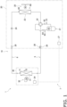
- Fig. 1 is a general configuration diagram of the air conditioning apparatus 1.
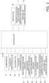
- Fig. 2 is a general control block configuration diagram of the air conditioning apparatus 1.
- the air conditioning apparatus 1 mainly includes an outdoor unit 20, an indoor unit 30, a liquid-side connection pipe 6 and a gas-side connection pipe 5 that connect the outdoor unit 20 and the indoor unit 30 to each other, a remote controller (not illustrated) serving as an input device and an output device, and a controller 7 that controls operations of the air conditioning apparatus 1.
- the air conditioning apparatus 1 performs a refrigeration cycle in which a refrigerant enclosed in a refrigerant circuit 10 is compressed, cooled or condensed, decompressed, heated or evaporated, and then compressed again.
- the refrigerant circuit 10 is filled with a refrigerant for performing a vapor compression refrigeration cycle.
- the refrigerant is a refrigerant having flammability.
- the refrigerant circuit 10 is filled with a refrigeration oil together with the refrigerant having flammability.
- the compressor 21 is a device that compresses the refrigerant with a low pressure in the refrigeration cycle until the refrigerant becomes a high-pressure refrigerant.
- a compressor having a hermetically sealed structure in which a compression element (not illustrated) of positive-displacement type, such as rotary type or scroll type, is rotationally driven by a compressor motor is used as the compressor 21.
- the compressor motor is for changing the capacity, and has an operational frequency that can be controlled by an inverter.
- the four-way switching valve 22, by switching the connection state, can switch the state between a cooling operation connection state in which the discharge side of the compressor 21 is connected to the outdoor heat exchanger 23 and the suction side of the compressor 21 is connected to the gas-side shutoff valve 28, and a heating operation connection state in which the discharge side of the compressor 21 is connected to the gas-side shutoff valve 28 and the suction side of the compressor 21 is connected to the outdoor heat exchanger 23.
- the outdoor heat exchanger 23 is a heat exchanger that functions as a condenser for the high-pressure refrigerant in the refrigeration cycle during cooling operation and that functions as an evaporator for the low-pressure refrigerant in the refrigeration cycle during heating operation.
- the outdoor fan 25 sucks outdoor air into the outdoor unit 20, causes the outdoor air to exchange heat with the refrigerant in the outdoor heat exchanger 23, and then generates an air flow to be discharged to the outside.
- the outdoor fan 25 is rotationally driven by an outdoor fan motor.
- the gas-side shutoff valve 28 is a manual valve disposed in a connection portion of the outdoor unit 20 with respect to the gas-side connection pipe 5.
- the outdoor unit 20 includes, for example, a discharge pressure sensor 61, a discharge temperature sensor 62, a suction pressure sensor 63, a suction temperature sensor 64, an outdoor heat-exchange temperature sensor 65, and an outdoor air temperature sensor 66.
- Each of the sensors is electrically connected to the outdoor-unit control unit 27, and transmits a detection signal to the outdoor-unit control unit 27.
- the discharge pressure sensor 61 detects the pressure of the refrigerant flowing through a discharge pipe that connects the discharge side of the compressor 21 to one of connecting ports of the four-way switching valve 22.
- the discharge temperature sensor 62 detects the temperature of the refrigerant flowing through the discharge pipe.
- the suction pressure sensor 63 detects the pressure of the refrigerant flowing through a suction pipe that connects the suction side of the compressor 21 to one of the connecting ports of the four-way switching valve 22.
- the suction temperature sensor 64 detects the temperature of the refrigerant flowing through the suction pipe.
- the outdoor heat-exchange temperature sensor 65 detects the temperature of the refrigerant flowing through the outlet on the liquid side of the outdoor heat exchanger 23 opposite to the side connected to the four-way switching valve 22.
- the outdoor air temperature sensor 66 detects the outdoor air temperature before the air passes through the outdoor heat exchanger 23.
- the indoor unit 30 is installed on a wall surface or a ceiling in a room that is a subject space.
- the indoor unit 30 is connected to the outdoor unit 20 via the liquid-side connection pipe 6 and the gas-side connection pipe 5, and constitutes a part of the refrigerant circuit 10.
- a case in which one indoor unit 30 is connected to one outdoor unit 20 is described as an example, but a plurality of indoor units may be connected in parallel to one outdoor unit 20.
- the indoor unit 30 includes an indoor heat exchanger 31 and an indoor fan 32.
- the indoor fan 32 sucks indoor air into the indoor unit 30, causes the indoor air to exchange heat with the refrigerant in the indoor heat exchanger 31, and then generates an air flow to be discharged to the outside.
- the indoor fan 32 is rotationally driven by an indoor fan motor.
- the indoor unit 30 includes an indoor-unit control unit 34 that controls operations of respective sections constituting the indoor unit 30.
- the indoor-unit control unit 34 includes a microcomputer including a CPU, a memory, and so forth.
- the indoor-unit control unit 34 is connected to the outdoor-unit control unit 27 via a communication line, and transmits and receives a control signal and so forth.
- the outdoor-unit control unit 27 is connected to the indoor-unit control unit 34 via the communication line, thereby constituting the controller 7 that controls operations of the air conditioning apparatus 1.
- the controller 7 mainly includes a processor such as a central processing unit (CPU) and memories such as a ROM and a RAM. Various processing and control by the controller 7 are provided when respective sections included in the outdoor-unit control unit 27 and/or the indoor-unit control unit 34 function together.
- a processor such as a central processing unit (CPU)
- memories such as a ROM and a RAM.
- the operating modes include a cooling operating mode and a heating operating mode.
- the controller 7 determines whether the operating mode is the cooling operating mode or the heating operating mode and executes the determined mode based on an instruction received from the remote controller or the like.
- the connection state of the four-way switching valve 22 in the cooling operating mode, is in the cooling operation connection state in which the discharge side of the compressor 21 is connected to the outdoor heat exchanger 23 and the suction side of the compressor 21 is connected to the gas-side shutoff valve 28, and the refrigerant filled in the refrigerant circuit 10 is circulated mainly sequentially in the compressor 21, the outdoor heat exchanger 23, the outdoor expansion valve 24, and the indoor heat exchanger 31.
- the refrigerant circuit 10 when the cooling operating mode is started, the refrigerant is sucked into the compressor 21, compressed, and then discharged.
- the compressor 21 performs capacity control in accordance with a cooling load required for the indoor unit 30.
- the gas refrigerant discharged from the compressor 21 passes through the four-way switching valve 22 and flows into the gas-side end of the outdoor heat exchanger 23.
- the gas refrigerant which has flowed into the gas-side end of the outdoor heat exchanger 23 exchanges heat with outdoor-side air supplied by the outdoor fan 25, hence is condensed and turns into a liquid refrigerant in the outdoor heat exchanger 23, and flows out from the liquid-side end of the outdoor heat exchanger 23.
- the refrigerant which has flowed out from the liquid-side end of the outdoor heat exchanger 23 is decompressed when passing through the outdoor expansion valve 24.
- the refrigerant decompressed at the outdoor expansion valve 24 passes through the liquid-side shutoff valve 29 and the liquid-side connection pipe 6, and flows into the indoor unit 30.
- the refrigerant which has flowed into the indoor unit 30 flows into the indoor heat exchanger 31; exchanges heat with the indoor air supplied by the indoor fan 32, hence is evaporated, and turns into a gas refrigerant in the indoor heat exchanger 31; and flows out from the gas-side end of the indoor heat exchanger 31.
- the gas refrigerant which has flowed out from the gas-side end of the indoor heat exchanger 31 flows to the gas-side connection pipe 5.
- the refrigerant which has flowed through the gas-side connection pipe 5 passes through the gas-side shutoff valve 28 and the four-way switching valve 22, and is sucked into the compressor 21 again.
- the connection state of the four-way switching valve 22 in the heating operating mode, is in the heating operation connection state in which the discharge side of the compressor 21 is connected to the gas-side shutoff valve 28 and the suction side of the compressor 21 is connected to the outdoor heat exchanger 23, and the refrigerant filled in the refrigerant circuit 10 is circulated mainly sequentially in the compressor 21, the indoor heat exchanger 31, the outdoor expansion valve 24, and the outdoor heat exchanger 23.
- the refrigerant circuit 10 when the heating operating mode is started, the refrigerant is sucked into the compressor 21, compressed, and then discharged.
- the gas refrigerant discharged from the compressor 21 flows through the four-way switching valve 22 and the gas-side connection pipe 5, and then flows into the indoor unit 30.
- the refrigerant which has flowed into the indoor unit 30 flows into the gas-side end of the indoor heat exchanger 31; exchanges heat with the indoor air supplied by the indoor fan 32, hence is condensed, and turns into a refrigerant in a gas-liquid two-phase state or a liquid refrigerant in the indoor heat exchanger 31; and flows out from the liquid-side end of the indoor heat exchanger 31.
- the refrigerant which has flowed out from the liquid-side end of the indoor heat exchanger 31 flows to the liquid-side connection pipe 6.
- the refrigerant which has flowed through the liquid-side connection pipe 6 flows into the outdoor unit 20, passes through the liquid-side shutoff valve 29, and is decompressed to a low pressure in the refrigeration cycle at the outdoor expansion valve 24.
- the refrigerant decompressed at the outdoor expansion valve 24 flows into the liquid-side end of the outdoor heat exchanger 23.
- the refrigerant which has flowed in from the liquid-side end of the outdoor heat exchanger 23 exchanges heat with the outdoor air supplied by the outdoor fan 25, hence is evaporated and turns into a gas refrigerant in the outdoor heat exchanger 23, and flows out from the gas-side end of the outdoor heat exchanger 23.
- the refrigerant which has flowed out from the gas-side end of the outdoor heat exchanger 23 passes through the four-way switching valve 22 and is sucked into the compressor 21 again.
- the air conditioning apparatus 1 is installed such that the outdoor unit 20 filled with a predetermined amount of the refrigerant and the indoor unit 30 not filled with the refrigerant are carried into an installation site in a state of being separated from each other, and are connected to each other by the gas-side connection pipe 5 and the liquid-side connection pipe 6.
- the lengths of the gas-side connection pipe 5 and the liquid-side connection pipe 6 that connect the outdoor unit 20 and the indoor unit 30 to each other differ according to the conditions of the installation site.
- an amount of the refrigerant smaller than an amount of refrigerant required to appropriately perform a refrigeration cycle in the refrigerant circuit 10 is enclosed in advance in the outdoor unit 20.
- the refrigerant circuit 10 is formed by connecting the outdoor unit 20 and the indoor unit 30 to each other by the gas-side connection pipe 5 and the liquid-side connection pipe 6, the refrigerant, which is insufficient for appropriately performing the refrigeration cycle, is additionally charged from the service port 26.
- a refrigerant cylinder is connected to the service port 26, and the refrigerant is additionally charged into the refrigerant circuit 10.
- the refrigerant When the refrigerant is additionally charged into the refrigerant circuit 10 via the service port 26, the refrigerant may be charged into the refrigerant circuit 10 while the refrigeration cycle is performed by the compressor 21 being driven. When the additional charging of the predetermined amount of the refrigerant is finished, the service port 26 is closed.
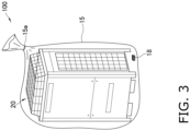
- the outdoor unit 20 is stored and transported in a state of being packaged with a packaging material 15.
- a packaging unit 100 is constituted of the outdoor unit 20 and the packaging material 15.
- the service port 26, the liquid-side shutoff valve 29, and the gas-side shutoff valve 28 are each closed in a state in which the refrigerant having flammability is enclosed in the outdoor unit 20 packaged with the packaging material 15 by an amount equal to or more than an amount of the refrigerant that becomes an atmospheric pressure at an ambient temperature of -40°C and less than an amount of the refrigerant that becomes 0.2 MPa at an ambient temperature of 20°C.
- the packaging material 15 packages the entire outdoor unit 20 and isolates the outdoor unit 20 from air outside the packaging material 15.
- the packaging material 15 is formed in a bag shape made of a material having no air permeability and is sealed at a fastening portion 15a in a state in which the outdoor unit 20 is packaged.
- a deoxidizer 18 is disposed on the periphery of the outdoor unit 20 in the internal space of the packaging material 15. By using the deoxidizer 18 in this way, the internal space of the packaging material 15 is maintained in a state in which the oxygen concentration is low.
- the disposition of the deoxidizer 18 is not limited, but when the outdoor unit 20 is filled with a refrigerant having flammability and having a specific gravity greater than that of the atmosphere, the deoxidizer 18 is preferably disposed at a height position lower than the service port 26, the liquid-side shutoff valve 29, and the gas-side shutoff valve 28.
- the internal space of the packaging material 15 may be filled with an inert gas.
- the outdoor unit 20 is stored in a state of the packaging unit 100, and is transported to an installation site.
- the packaging unit 100 is preferably stored and transported in an environment at an ambient temperature of -4°C or higher.
- the packaging material 15 is removed at the time of installation.
Landscapes
- Engineering & Computer Science (AREA)
- Mechanical Engineering (AREA)
- General Engineering & Computer Science (AREA)
- Chemical & Material Sciences (AREA)
- Combustion & Propulsion (AREA)
- Physics & Mathematics (AREA)
- Thermal Sciences (AREA)
- Health & Medical Sciences (AREA)
- Public Health (AREA)
- Business, Economics & Management (AREA)
- Emergency Management (AREA)
- Air Conditioning Control Device (AREA)
Abstract
Description
- The present disclosure relates to an air conditioning unit and a packaging unit.
- In recent years, as interest in the global environment has increased, refrigerants with low global warming potential (hereinafter referred to as GWP) values, which do not have a great influence on the destruction of the ozone layer and global warming, have been receiving attention. Some of such refrigerants have flammability, and it is required to ensure safety so that the refrigerants are not ignited.
- For example, PTL 1 (
Japanese Unexamined Patent Application Publication No. 2011-094871 - However, it is possible to reduce the amount of the refrigerant that is additionally charged into an air conditioning unit at a site where the air conditioning unit is installed, and hence there may be cases where it is desirable to enclose even a refrigerant having flammability in the air conditioning unit in advance. It is required to safely store the air conditioning unit in which the refrigerant having flammability is enclosed. In addition, it is desirable that, during storage, substances that become unnecessary during operation after installation are not mixed into the air conditioning unit.
- In an air conditioning unit according to a first aspect, a refrigerant having flammability is enclosed. An enclosure amount of the refrigerant having the flammability is equal to or more than an amount of the refrigerant that becomes an atmospheric pressure at an ambient temperature of -40°C and less than an amount of the refrigerant that becomes 0.2 MPa at an ambient temperature of 20°C.
- In this air conditioning unit, although the refrigerant having the flammability is enclosed, the amount of the refrigerant is less than the amount of the refrigerant that becomes 0.2 MPa at the ambient temperature of 20°C, and is suppressed to be small. Thus, even when the refrigerant leaks, ignition is suppressed. In addition, in this air conditioning unit, the enclosure amount of the refrigerant having the flammability is equal to or more than the amount of the refrigerant that becomes the atmospheric pressure at the ambient temperature of -40°C. Thus, even when the ambient temperature decreases during storage, the pressure of the portion in which the refrigerant having the flammability is enclosed is likely to be maintained at the atmospheric pressure or higher, and mixing of air from the surroundings is suppressed. Accordingly, safe storage can be provided while mixing of unnecessary substances is suppressed.
- An air conditioning unit according to a second aspect is the air conditioning unit of the first aspect, and is an outdoor unit that is connected to an indoor unit and used.
- This air conditioning unit can be safely stored while suppressing mixing of air into the outdoor unit.
- An air conditioning unit according to a third aspect is the air conditioning unit of the first aspect or the second aspect, in which the refrigerant having the flammability contains one type or two or more types selected from the group consisting of R290, R600, and R600a.
- A packaging unit according to a fourth aspect includes the air conditioning unit of any one of the first aspect to the third aspect; and a packaging material that packages the air conditioning unit. The air conditioning unit is isolated from air outside the packaging material.
- In this packaging unit, since the air conditioning unit is packaged with the packaging material, the packaging unit can suppress mixing of air outside the packaging material into the air conditioning unit.
- A packaging unit according to a fifth aspect is the packaging unit of the fourth aspect, in which the packaging material contains one type or two or more types selected from the group consisting of vinyl chloride, polyethylene, and polypropylene.
- This packaging unit facilitates packaging work of the air conditioning unit.
- A packaging unit according to a sixth aspect is the packaging unit of the fourth aspect or the fifth aspect, in which an internal space of the packaging material is in a low oxygen state.
- In this packaging unit, even when the refrigerant leaks from the air conditioning unit, ignition in the internal space of the packaging material is suppressed.
- A packaging unit according to a seventh aspect is the packaging unit of any one of the fourth aspect to the sixth aspect, in which an inert gas is enclosed in an internal space of the packaging material.
- In this packaging unit, even when the refrigerant leaks from the air conditioning unit, ignition in the internal space of the packaging material is suppressed.
- A packaging unit according to an eighth aspect is the packaging unit of any one of the fourth aspect to the seventh aspect, and further includes a deoxidizer. The deoxidizer is disposed in the internal space of the packaging material.
- This packaging unit can reduce the oxygen concentration around the air conditioning unit.
-
-
Fig. 1 is a general configuration diagram of an air conditioning apparatus. -
Fig. 2 is a general control block configuration diagram of the air conditioning apparatus. -
Fig. 3 is a general configuration diagram of a packaging unit. - An air conditioning unit may be a device in which a refrigerant having flammability is enclosed and that can perform a refrigeration cycle, or may be a partial component for performing a refrigeration cycle. For example, the air conditioning unit may be an outdoor unit that constitutes a refrigerant circuit by being connected to one indoor unit or a plurality of indoor units via a refrigerant pipe.
- Examples of the refrigerant having flammability include a highly flammable refrigerant of class A3 or B3, a flammable refrigerant of class A2 or B2, and a slightly flammable refrigerant of class A2L or B2L in ASHRAE Safety Group. The refrigerant having flammability may be one type or two or more types selected from the group consisting of R290, R600, and R600a.
- The refrigerant having flammability is enclosed in the air conditioning unit. An enclosure amount of the refrigerant having flammability enclosed in the air conditioning unit is equal to or more than an amount of the refrigerant that becomes an atmospheric pressure at an ambient temperature of -40°C and less than an amount of the refrigerant that becomes 0.2 MPa at an ambient temperature of 20°C. Although the refrigerant having flammability is enclosed in the air conditioning unit, the amount of the refrigerant is less than the amount of the refrigerant that becomes 0.2 MPa at the ambient temperature of 20°C and is suppressed to be small. Thus, even when the refrigerant leaks from the air conditioning unit, ignition is suppressed, and storage and transportation can be performed safely. In addition, in this air conditioning unit, the enclosure amount of the refrigerant having flammability is equal to or more than the amount of the refrigerant that becomes the atmospheric pressure at the ambient temperature of -40°C. Thus, even when the ambient temperature decreases during storage or transportation, the pressure of the portion in which the refrigerant having flammability is enclosed is likely to be maintained at the atmospheric pressure or higher. Thus, mixing of air from the surroundings into the air conditioning unit is suppressed. Thus, when a refrigeration cycle operation is performed after the air conditioning unit is installed, the reliability of the operation can be improved.
- The air conditioning unit is preferably stored in a state of being packaged with a packaging material. Such a packaging material preferably has gas barrier properties. For example, the packaging material preferably contains one type or two or more types selected from the group consisting of vinyl chloride, polyethylene, and polypropylene. Thus, even when the refrigerant having flammability leaks from the air conditioning unit, the spread of the leakage toward the outside of the packaging material is suppressed. In addition, mixing of air or moisture outside the packaging material into the air conditioning unit is suppressed.
- The internal space of the packaging material is preferably in a low oxygen state. As the low oxygen state, for example, the oxygen concentration may be 10.0% or less, more preferably 8.0% or less, and further preferably a deoxidized state. As the deoxidized state, the oxygen concentration may be 1.0% or less, and more preferably 0.1% or less. From the viewpoint of easily maintaining the oxygen concentration in the internal space of the packaging material low, the air conditioning unit is preferably stored in a state in which a deoxidizer is disposed in the internal space of the packaging material. As such a deoxidizer, a self-reaction type deoxidizer that already has moisture necessary for reaction and starts absorption of oxygen from the moment of contact with air is preferable. For example, iron powder, zeolite, sodium chloride, activated carbon, and a mixture thereof can be preferably used. The amount of the deoxidizer to be used is preferably, for example, an amount that attains an absorption amount equal to or more than a value obtained by multiplying the internal space of the packaging material (the volume inside the packaging material minus the volume of the air conditioning unit) by the percentage of oxygen in air (21%).
- An inert gas is preferably enclosed in the internal space of the packaging material. The inert gas may be any one of helium, neon, argon, krypton, xenon, radon, nitrogen, carbon dioxide, fluorocarbon (excluding a refrigerant having flammability), and a mixed gas thereof. The inert gas may be a flue gas having a low oxygen concentration, such as an exhaust gas generated by combustion of fuel. In addition, when the inert gas is enclosed in the internal space of the packaging material, the deoxidizer may be further used.
- Hereinafter, an air conditioning apparatus 1 in which an outdoor unit as an air conditioning unit is used will be described as an example.
-
Fig. 1 is a general configuration diagram of the air conditioning apparatus 1.Fig. 2 is a general control block configuration diagram of the air conditioning apparatus 1. - The air conditioning apparatus 1 is an apparatus that controls the condition of air in a subject space by performing a vapor compression refrigeration cycle.
- The air conditioning apparatus 1 mainly includes an
outdoor unit 20, anindoor unit 30, a liquid-side connection pipe 6 and a gas-side connection pipe 5 that connect theoutdoor unit 20 and theindoor unit 30 to each other, a remote controller (not illustrated) serving as an input device and an output device, and acontroller 7 that controls operations of the air conditioning apparatus 1. - The air conditioning apparatus 1 performs a refrigeration cycle in which a refrigerant enclosed in a
refrigerant circuit 10 is compressed, cooled or condensed, decompressed, heated or evaporated, and then compressed again. In the present embodiment, therefrigerant circuit 10 is filled with a refrigerant for performing a vapor compression refrigeration cycle. The refrigerant is a refrigerant having flammability. In addition, therefrigerant circuit 10 is filled with a refrigeration oil together with the refrigerant having flammability. - The
outdoor unit 20 is connected to theindoor unit 30 via the liquid-side connection pipe 6 and the gas-side connection pipe 5, and constitutes a part of therefrigerant circuit 10. Theoutdoor unit 20 mainly includes acompressor 21, a four-way switching valve 22, anoutdoor heat exchanger 23, anoutdoor expansion valve 24, anoutdoor fan 25, a liquid-side shutoff valve 29, a gas-side shutoff valve 28, and aservice port 26. - The
compressor 21 is a device that compresses the refrigerant with a low pressure in the refrigeration cycle until the refrigerant becomes a high-pressure refrigerant. In this case, a compressor having a hermetically sealed structure in which a compression element (not illustrated) of positive-displacement type, such as rotary type or scroll type, is rotationally driven by a compressor motor is used as thecompressor 21. The compressor motor is for changing the capacity, and has an operational frequency that can be controlled by an inverter. - The four-
way switching valve 22, by switching the connection state, can switch the state between a cooling operation connection state in which the discharge side of thecompressor 21 is connected to theoutdoor heat exchanger 23 and the suction side of thecompressor 21 is connected to the gas-side shutoff valve 28, and a heating operation connection state in which the discharge side of thecompressor 21 is connected to the gas-side shutoff valve 28 and the suction side of thecompressor 21 is connected to theoutdoor heat exchanger 23. - The
outdoor heat exchanger 23 is a heat exchanger that functions as a condenser for the high-pressure refrigerant in the refrigeration cycle during cooling operation and that functions as an evaporator for the low-pressure refrigerant in the refrigeration cycle during heating operation. - The
outdoor fan 25 sucks outdoor air into theoutdoor unit 20, causes the outdoor air to exchange heat with the refrigerant in theoutdoor heat exchanger 23, and then generates an air flow to be discharged to the outside. Theoutdoor fan 25 is rotationally driven by an outdoor fan motor. - The
outdoor expansion valve 24 is provided between a liquid-side end portion of theoutdoor heat exchanger 23 and the liquid-side shutoff valve 29. Theoutdoor expansion valve 24 may be a mechanical expansion valve used together with a capillary tube or a temperature sensitive tube, but is preferably an electric expansion valve that can adjust a valve opening degree by control. - The liquid-
side shutoff valve 29 is a manual valve disposed in a connection portion of theoutdoor unit 20 with respect to the liquid-side connection pipe 6. - The gas-
side shutoff valve 28 is a manual valve disposed in a connection portion of theoutdoor unit 20 with respect to the gas-side connection pipe 5. - The
service port 26 is provided adjacent to the gas-side shutoff valve 28, and is a manual valve disposed in the connection portion of theoutdoor unit 20 with respect to the gas-side connection pipe 5. - The
outdoor unit 20 includes an outdoor-unit control unit 27 that controls operations of respective sections constituting theoutdoor unit 20. The outdoor-unit control unit 27 includes a microcomputer including a CPU, a memory, and so forth. The outdoor-unit control unit 27 is connected to an indoor-unit control unit 34 of eachindoor unit 30 via a communication line, and transmits and receives a control signal and so forth. - The
outdoor unit 20 includes, for example, adischarge pressure sensor 61, adischarge temperature sensor 62, asuction pressure sensor 63, asuction temperature sensor 64, an outdoor heat-exchange temperature sensor 65, and an outdoorair temperature sensor 66. Each of the sensors is electrically connected to the outdoor-unit control unit 27, and transmits a detection signal to the outdoor-unit control unit 27. Thedischarge pressure sensor 61 detects the pressure of the refrigerant flowing through a discharge pipe that connects the discharge side of thecompressor 21 to one of connecting ports of the four-way switching valve 22. Thedischarge temperature sensor 62 detects the temperature of the refrigerant flowing through the discharge pipe. Thesuction pressure sensor 63 detects the pressure of the refrigerant flowing through a suction pipe that connects the suction side of thecompressor 21 to one of the connecting ports of the four-way switching valve 22. Thesuction temperature sensor 64 detects the temperature of the refrigerant flowing through the suction pipe. The outdoor heat-exchange temperature sensor 65 detects the temperature of the refrigerant flowing through the outlet on the liquid side of theoutdoor heat exchanger 23 opposite to the side connected to the four-way switching valve 22. The outdoorair temperature sensor 66 detects the outdoor air temperature before the air passes through theoutdoor heat exchanger 23. - The
indoor unit 30 is installed on a wall surface or a ceiling in a room that is a subject space. Theindoor unit 30 is connected to theoutdoor unit 20 via the liquid-side connection pipe 6 and the gas-side connection pipe 5, and constitutes a part of therefrigerant circuit 10. In the present embodiment, a case in which oneindoor unit 30 is connected to oneoutdoor unit 20 is described as an example, but a plurality of indoor units may be connected in parallel to oneoutdoor unit 20. - The
indoor unit 30 includes anindoor heat exchanger 31 and anindoor fan 32. - The liquid side of the
indoor heat exchanger 31 is connected to the liquid-side connection pipe 6, and the gas-side end thereof is connected to the gas-side connection pipe 5. Theindoor heat exchanger 31 is a heat exchanger that functions as an evaporator for the low-pressure refrigerant in the refrigeration cycle during cooling operation and that functions as a condenser for the high-pressure refrigerant in the refrigeration cycle during heating operation. - The
indoor fan 32 sucks indoor air into theindoor unit 30, causes the indoor air to exchange heat with the refrigerant in theindoor heat exchanger 31, and then generates an air flow to be discharged to the outside. Theindoor fan 32 is rotationally driven by an indoor fan motor. - In addition, the
indoor unit 30 includes an indoor-unit control unit 34 that controls operations of respective sections constituting theindoor unit 30. The indoor-unit control unit 34 includes a microcomputer including a CPU, a memory, and so forth. The indoor-unit control unit 34 is connected to the outdoor-unit control unit 27 via a communication line, and transmits and receives a control signal and so forth. - The
indoor unit 30 includes, for example, an indoor liquid-side heat-exchange temperature sensor 71 and an indoorair temperature sensor 72. Each of the sensors is electrically connected to the indoor-unit control unit 34, and transmits a detection signal to the indoor-unit control unit 34. The indoor liquid-side heat-exchange temperature sensor 71 detects the temperature of the refrigerant flowing through the outlet on the liquid side of theindoor heat exchanger 31 opposite to the side connected to the four-way switching valve 22. The indoorair temperature sensor 72 detects the indoor air temperature before the air passes through theindoor heat exchanger 31. - In the air conditioning apparatus 1, the outdoor-
unit control unit 27 is connected to the indoor-unit control unit 34 via the communication line, thereby constituting thecontroller 7 that controls operations of the air conditioning apparatus 1. - The
controller 7 mainly includes a processor such as a central processing unit (CPU) and memories such as a ROM and a RAM. Various processing and control by thecontroller 7 are provided when respective sections included in the outdoor-unit control unit 27 and/or the indoor-unit control unit 34 function together. - Operating modes are described below.
- The operating modes include a cooling operating mode and a heating operating mode.
- The
controller 7 determines whether the operating mode is the cooling operating mode or the heating operating mode and executes the determined mode based on an instruction received from the remote controller or the like. - In the air conditioning apparatus 1, in the cooling operating mode, the connection state of the four-
way switching valve 22 is in the cooling operation connection state in which the discharge side of thecompressor 21 is connected to theoutdoor heat exchanger 23 and the suction side of thecompressor 21 is connected to the gas-side shutoff valve 28, and the refrigerant filled in therefrigerant circuit 10 is circulated mainly sequentially in thecompressor 21, theoutdoor heat exchanger 23, theoutdoor expansion valve 24, and theindoor heat exchanger 31. - More specifically, in the
refrigerant circuit 10, when the cooling operating mode is started, the refrigerant is sucked into thecompressor 21, compressed, and then discharged. - The
compressor 21 performs capacity control in accordance with a cooling load required for theindoor unit 30. The gas refrigerant discharged from thecompressor 21 passes through the four-way switching valve 22 and flows into the gas-side end of theoutdoor heat exchanger 23. - The gas refrigerant which has flowed into the gas-side end of the
outdoor heat exchanger 23 exchanges heat with outdoor-side air supplied by theoutdoor fan 25, hence is condensed and turns into a liquid refrigerant in theoutdoor heat exchanger 23, and flows out from the liquid-side end of theoutdoor heat exchanger 23. - The refrigerant which has flowed out from the liquid-side end of the
outdoor heat exchanger 23 is decompressed when passing through theoutdoor expansion valve 24. The refrigerant decompressed at theoutdoor expansion valve 24 passes through the liquid-side shutoff valve 29 and the liquid-side connection pipe 6, and flows into theindoor unit 30. - The refrigerant which has flowed into the
indoor unit 30 flows into theindoor heat exchanger 31; exchanges heat with the indoor air supplied by theindoor fan 32, hence is evaporated, and turns into a gas refrigerant in theindoor heat exchanger 31; and flows out from the gas-side end of theindoor heat exchanger 31. The gas refrigerant which has flowed out from the gas-side end of theindoor heat exchanger 31 flows to the gas-side connection pipe 5. - The refrigerant which has flowed through the gas-
side connection pipe 5 passes through the gas-side shutoff valve 28 and the four-way switching valve 22, and is sucked into thecompressor 21 again. - In the air conditioning apparatus 1, in the heating operating mode, the connection state of the four-
way switching valve 22 is in the heating operation connection state in which the discharge side of thecompressor 21 is connected to the gas-side shutoff valve 28 and the suction side of thecompressor 21 is connected to theoutdoor heat exchanger 23, and the refrigerant filled in therefrigerant circuit 10 is circulated mainly sequentially in thecompressor 21, theindoor heat exchanger 31, theoutdoor expansion valve 24, and theoutdoor heat exchanger 23. - More specifically, in the
refrigerant circuit 10, when the heating operating mode is started, the refrigerant is sucked into thecompressor 21, compressed, and then discharged. The gas refrigerant discharged from thecompressor 21 flows through the four-way switching valve 22 and the gas-side connection pipe 5, and then flows into theindoor unit 30. - The refrigerant which has flowed into the
indoor unit 30 flows into the gas-side end of theindoor heat exchanger 31; exchanges heat with the indoor air supplied by theindoor fan 32, hence is condensed, and turns into a refrigerant in a gas-liquid two-phase state or a liquid refrigerant in theindoor heat exchanger 31; and flows out from the liquid-side end of theindoor heat exchanger 31. The refrigerant which has flowed out from the liquid-side end of theindoor heat exchanger 31 flows to the liquid-side connection pipe 6. - The refrigerant which has flowed through the liquid-
side connection pipe 6 flows into theoutdoor unit 20, passes through the liquid-side shutoff valve 29, and is decompressed to a low pressure in the refrigeration cycle at theoutdoor expansion valve 24. The refrigerant decompressed at theoutdoor expansion valve 24 flows into the liquid-side end of theoutdoor heat exchanger 23. - The refrigerant which has flowed in from the liquid-side end of the
outdoor heat exchanger 23 exchanges heat with the outdoor air supplied by theoutdoor fan 25, hence is evaporated and turns into a gas refrigerant in theoutdoor heat exchanger 23, and flows out from the gas-side end of theoutdoor heat exchanger 23. - The refrigerant which has flowed out from the gas-side end of the
outdoor heat exchanger 23 passes through the four-way switching valve 22 and is sucked into thecompressor 21 again. - The air conditioning apparatus 1 is installed such that the
outdoor unit 20 filled with a predetermined amount of the refrigerant and theindoor unit 30 not filled with the refrigerant are carried into an installation site in a state of being separated from each other, and are connected to each other by the gas-side connection pipe 5 and the liquid-side connection pipe 6. - The lengths of the gas-
side connection pipe 5 and the liquid-side connection pipe 6 that connect theoutdoor unit 20 and theindoor unit 30 to each other differ according to the conditions of the installation site. Thus, an amount of the refrigerant smaller than an amount of refrigerant required to appropriately perform a refrigeration cycle in therefrigerant circuit 10 is enclosed in advance in theoutdoor unit 20. Then, after therefrigerant circuit 10 is formed by connecting theoutdoor unit 20 and theindoor unit 30 to each other by the gas-side connection pipe 5 and the liquid-side connection pipe 6, the refrigerant, which is insufficient for appropriately performing the refrigeration cycle, is additionally charged from theservice port 26. Specifically, a refrigerant cylinder is connected to theservice port 26, and the refrigerant is additionally charged into therefrigerant circuit 10. When the refrigerant is additionally charged into therefrigerant circuit 10 via theservice port 26, the refrigerant may be charged into therefrigerant circuit 10 while the refrigeration cycle is performed by thecompressor 21 being driven. When the additional charging of the predetermined amount of the refrigerant is finished, theservice port 26 is closed. - As illustrated in
Fig. 3 , theoutdoor unit 20 is stored and transported in a state of being packaged with apackaging material 15. Specifically, apackaging unit 100 is constituted of theoutdoor unit 20 and thepackaging material 15. - The
service port 26, the liquid-side shutoff valve 29, and the gas-side shutoff valve 28 are each closed in a state in which the refrigerant having flammability is enclosed in theoutdoor unit 20 packaged with thepackaging material 15 by an amount equal to or more than an amount of the refrigerant that becomes an atmospheric pressure at an ambient temperature of -40°C and less than an amount of the refrigerant that becomes 0.2 MPa at an ambient temperature of 20°C. - The
packaging material 15 packages the entireoutdoor unit 20 and isolates theoutdoor unit 20 from air outside thepackaging material 15. Thepackaging material 15 is formed in a bag shape made of a material having no air permeability and is sealed at afastening portion 15a in a state in which theoutdoor unit 20 is packaged. - A
deoxidizer 18 is disposed on the periphery of theoutdoor unit 20 in the internal space of thepackaging material 15. By using thedeoxidizer 18 in this way, the internal space of thepackaging material 15 is maintained in a state in which the oxygen concentration is low. The disposition of thedeoxidizer 18 is not limited, but when theoutdoor unit 20 is filled with a refrigerant having flammability and having a specific gravity greater than that of the atmosphere, thedeoxidizer 18 is preferably disposed at a height position lower than theservice port 26, the liquid-side shutoff valve 29, and the gas-side shutoff valve 28. The internal space of thepackaging material 15 may be filled with an inert gas. - The
outdoor unit 20 is stored in a state of thepackaging unit 100, and is transported to an installation site. Thepackaging unit 100 is preferably stored and transported in an environment at an ambient temperature of -4°C or higher. Thepackaging material 15 is removed at the time of installation. - While the embodiment of the present disclosure has been described above, it is understood that the embodiment and details can be changed in various ways without departing from the gist and scope of the present disclosure described in the claims.
-
- 1
- air conditioning apparatus
- 7
- controller
- 10
- refrigerant circuit
- 15
- packaging material
- 18
- deoxidizer
- 20
- outdoor unit (air conditioning unit, outdoor unit)
- 21
- compressor
- 23
- outdoor heat exchanger
- 24
- outdoor expansion valve
- 25
- outdoor fan
- 30
- indoor unit (indoor unit)
- 31
- indoor heat exchanger
- 32
- indoor fan
- 100
- packaging unit
- PTL 1:
Japanese Unexamined Patent Application Publication No. 2011-094871
Claims (8)
- An air conditioning unit (20),wherein a refrigerant having flammability is enclosed, andwherein an enclosure amount of the refrigerant having the flammability is equal to or more than an amount of the refrigerant that becomes an atmospheric pressure at an ambient temperature of -40°C and less than an amount of the refrigerant that becomes 0.2 MPa at an ambient temperature of 20°C.
- The air conditioning unit according to claim 1, wherein the air conditioning unit is an outdoor unit (20) that is connected to an indoor unit (30) and used.
- The air conditioning unit according to claim 1 or 2, wherein the refrigerant having the flammability contains one type or two or more types selected from the group consisting of R290, R600, and R600a.
- A packaging unit (100) comprising:the air conditioning unit according to any one of claims 1 to 3; anda packaging material (15) that packages the air conditioning unit,wherein the air conditioning unit is isolated from air outside the packaging material.
- The packaging unit according to claim 4, wherein the packaging material contains one type or two or more types selected from the group consisting of vinyl chloride, polyethylene, and polypropylene.
- The packaging unit according to claim 4 or 5, wherein an internal space of the packaging material is in a low oxygen state.
- The packaging unit according to any one of claims 4 to 6, wherein an inert gas is enclosed in an internal space of the packaging material.
- The packaging unit according to any one of claims 4 to 7, further comprising a deoxidizer (18) disposed in an internal space of the packaging material.
Applications Claiming Priority (2)
| Application Number | Priority Date | Filing Date | Title |
|---|---|---|---|
| JP2022056624 | 2022-03-30 | ||
| PCT/JP2023/009180 WO2023189391A1 (en) | 2022-03-30 | 2023-03-09 | Air-conditioning unit and packaging unit |
Publications (2)
| Publication Number | Publication Date |
|---|---|
| EP4502495A1 true EP4502495A1 (en) | 2025-02-05 |
| EP4502495A4 EP4502495A4 (en) | 2025-07-23 |
Family
ID=88200766
Family Applications (1)
| Application Number | Title | Priority Date | Filing Date |
|---|---|---|---|
| EP23779417.7A Pending EP4502495A4 (en) | 2022-03-30 | 2023-03-09 | AIR CONDITIONING UNIT AND PACKAGING UNIT |
Country Status (5)
| Country | Link |
|---|---|
| US (1) | US20250012477A1 (en) |
| EP (1) | EP4502495A4 (en) |
| JP (2) | JP7824902B2 (en) |
| CN (1) | CN118974492A (en) |
| WO (1) | WO2023189391A1 (en) |
Family Cites Families (8)
| Publication number | Priority date | Publication date | Assignee | Title |
|---|---|---|---|---|
| JPH07332242A (en) * | 1994-06-14 | 1995-12-22 | Matsushita Refrig Co Ltd | Hermetic compressor |
| JP4520127B2 (en) * | 1998-05-26 | 2010-08-04 | パナソニック株式会社 | Air conditioner outdoor unit storage / transport / installation method and refrigeration unit storage / transport / installation method |
| JP3501678B2 (en) * | 1998-05-26 | 2004-03-02 | 松下電器産業株式会社 | Storage, transportation and installation of air conditioners |
| JP2000095276A (en) * | 1998-09-25 | 2000-04-04 | Matsushita Electric Ind Co Ltd | Air conditioner packing equipment |
| JP5253330B2 (en) * | 2009-08-26 | 2013-07-31 | 三菱電機株式会社 | Manufacturing method of air conditioner |
| JP2011094871A (en) | 2009-10-29 | 2011-05-12 | Mitsubishi Electric Corp | Refrigerating air conditioning device and installation method of the refrigerating air conditioning device |
| JP5310775B2 (en) * | 2011-04-20 | 2013-10-09 | 三菱電機株式会社 | Packing equipment |
| JP7164822B2 (en) * | 2018-09-28 | 2022-11-02 | ダイキン工業株式会社 | Refrigerant charging method |
-
2023
- 2023-03-09 WO PCT/JP2023/009180 patent/WO2023189391A1/en not_active Ceased
- 2023-03-09 EP EP23779417.7A patent/EP4502495A4/en active Pending
- 2023-03-09 CN CN202380031184.5A patent/CN118974492A/en active Pending
- 2023-03-09 JP JP2023036365A patent/JP7824902B2/en active Active
-
2024
- 2024-02-21 JP JP2024024479A patent/JP2024052703A/en active Pending
- 2024-09-19 US US18/889,544 patent/US20250012477A1/en active Pending
Also Published As
| Publication number | Publication date |
|---|---|
| JP7824902B2 (en) | 2026-03-05 |
| US20250012477A1 (en) | 2025-01-09 |
| JP2023152795A (en) | 2023-10-17 |
| JP2024052703A (en) | 2024-04-11 |
| EP4502495A4 (en) | 2025-07-23 |
| WO2023189391A1 (en) | 2023-10-05 |
| CN118974492A (en) | 2024-11-15 |
Similar Documents
| Publication | Publication Date | Title |
|---|---|---|
| EP3683524B1 (en) | Refrigeration apparatus | |
| JP2001133058A (en) | Refrigeration cycle device | |
| CN101501422A (en) | Air conditioner and cleaning method thereof | |
| CN110446898B (en) | Air conditioner | |
| EP2730863A1 (en) | Refrigeration and air conditioning device and method for controlling refrigeration and air conditioning device | |
| JP2008101837A (en) | Refrigeration cycle apparatus and control method thereof | |
| US20230203357A1 (en) | Use of composition as refrigerant, and refrigeration cycle apparatus | |
| US20230203356A1 (en) | Use of refrigerant in refrigeration cycle apparatus, and refrigeration cycle apparatus | |
| US9279607B2 (en) | Method of part replacement for refrigeration cycle apparatus | |
| WO2015140880A1 (en) | Compressor and refrigeration cycle apparatus | |
| JP2009257601A (en) | Air conditioning device | |
| US20250012477A1 (en) | Air conditioning unit and packaging unit | |
| US20170074561A1 (en) | Refrigeration cycle device | |
| WO2019130383A1 (en) | Air conditioning device | |
| JP6393181B2 (en) | Refrigeration cycle equipment | |
| JP7139850B2 (en) | refrigeration cycle equipment | |
| JP2020070941A (en) | Refrigeration cycle device | |
| JPH10259961A (en) | Air conditioner | |
| WO2020090760A1 (en) | Refrigerant cycle device | |
| JP7155804B2 (en) | Compressor and refrigeration cycle equipment | |
| EP4542133A1 (en) | Air conditioning device | |
| JP2020029965A (en) | Refrigeration cycle device | |
| JP2020003104A (en) | Air conditioner | |
| JP7139827B2 (en) | refrigeration cycle equipment | |
| JP2001221524A (en) | Air conditioner |
Legal Events
| Date | Code | Title | Description |
|---|---|---|---|
| STAA | Information on the status of an ep patent application or granted ep patent |
Free format text: STATUS: THE INTERNATIONAL PUBLICATION HAS BEEN MADE |
|
| PUAI | Public reference made under article 153(3) epc to a published international application that has entered the european phase |
Free format text: ORIGINAL CODE: 0009012 |
|
| STAA | Information on the status of an ep patent application or granted ep patent |
Free format text: STATUS: REQUEST FOR EXAMINATION WAS MADE |
|
| 17P | Request for examination filed |
Effective date: 20241015 |
|
| AK | Designated contracting states |
Kind code of ref document: A1 Designated state(s): AL AT BE BG CH CY CZ DE DK EE ES FI FR GB GR HR HU IE IS IT LI LT LU LV MC ME MK MT NL NO PL PT RO RS SE SI SK SM TR |
|
| DAV | Request for validation of the european patent (deleted) | ||
| DAX | Request for extension of the european patent (deleted) | ||
| A4 | Supplementary search report drawn up and despatched |
Effective date: 20250620 |
|
| RIC1 | Information provided on ipc code assigned before grant |
Ipc: F25B 1/00 20060101AFI20250613BHEP Ipc: B65D 85/68 20060101ALI20250613BHEP Ipc: F25B 45/00 20060101ALI20250613BHEP Ipc: F24F 11/89 20180101ALI20250613BHEP |
|
| P01 | Opt-out of the competence of the unified patent court (upc) registered |
Free format text: CASE NUMBER: UPC_APP_3799_4502495/2025 Effective date: 20250820 |