EP4502484A1 - Thermal load prediction system - Google Patents
Thermal load prediction system Download PDFInfo
- Publication number
- EP4502484A1 EP4502484A1 EP23780239.2A EP23780239A EP4502484A1 EP 4502484 A1 EP4502484 A1 EP 4502484A1 EP 23780239 A EP23780239 A EP 23780239A EP 4502484 A1 EP4502484 A1 EP 4502484A1
- Authority
- EP
- European Patent Office
- Prior art keywords
- air
- indoor
- thermal load
- unit
- temperature
- Prior art date
- Legal status (The legal status is an assumption and is not a legal conclusion. Google has not performed a legal analysis and makes no representation as to the accuracy of the status listed.)
- Pending
Links
Images


Classifications
-
- F—MECHANICAL ENGINEERING; LIGHTING; HEATING; WEAPONS; BLASTING
- F24—HEATING; RANGES; VENTILATING
- F24F—AIR-CONDITIONING; AIR-HUMIDIFICATION; VENTILATION; USE OF AIR CURRENTS FOR SCREENING
- F24F11/00—Control or safety arrangements
- F24F11/30—Control or safety arrangements for purposes related to the operation of the system, e.g. for safety or monitoring
-
- F—MECHANICAL ENGINEERING; LIGHTING; HEATING; WEAPONS; BLASTING
- F24—HEATING; RANGES; VENTILATING
- F24F—AIR-CONDITIONING; AIR-HUMIDIFICATION; VENTILATION; USE OF AIR CURRENTS FOR SCREENING
- F24F11/00—Control or safety arrangements
- F24F11/30—Control or safety arrangements for purposes related to the operation of the system, e.g. for safety or monitoring
- F24F11/46—Improving electric energy efficiency or saving
-
- F—MECHANICAL ENGINEERING; LIGHTING; HEATING; WEAPONS; BLASTING
- F24—HEATING; RANGES; VENTILATING
- F24F—AIR-CONDITIONING; AIR-HUMIDIFICATION; VENTILATION; USE OF AIR CURRENTS FOR SCREENING
- F24F11/00—Control or safety arrangements
- F24F11/62—Control or safety arrangements characterised by the type of control or by internal processing, e.g. using fuzzy logic, adaptive control or estimation of values
-
- F—MECHANICAL ENGINEERING; LIGHTING; HEATING; WEAPONS; BLASTING
- F24—HEATING; RANGES; VENTILATING
- F24F—AIR-CONDITIONING; AIR-HUMIDIFICATION; VENTILATION; USE OF AIR CURRENTS FOR SCREENING
- F24F11/00—Control or safety arrangements
- F24F11/62—Control or safety arrangements characterised by the type of control or by internal processing, e.g. using fuzzy logic, adaptive control or estimation of values
- F24F11/63—Electronic processing
-
- F—MECHANICAL ENGINEERING; LIGHTING; HEATING; WEAPONS; BLASTING
- F24—HEATING; RANGES; VENTILATING
- F24F—AIR-CONDITIONING; AIR-HUMIDIFICATION; VENTILATION; USE OF AIR CURRENTS FOR SCREENING
- F24F11/00—Control or safety arrangements
- F24F11/62—Control or safety arrangements characterised by the type of control or by internal processing, e.g. using fuzzy logic, adaptive control or estimation of values
- F24F11/63—Electronic processing
- F24F11/64—Electronic processing using pre-stored data
-
- G—PHYSICS
- G05—CONTROLLING; REGULATING
- G05B—CONTROL OR REGULATING SYSTEMS IN GENERAL; FUNCTIONAL ELEMENTS OF SUCH SYSTEMS; MONITORING OR TESTING ARRANGEMENTS FOR SUCH SYSTEMS OR ELEMENTS
- G05B13/00—Adaptive control systems, i.e. systems automatically adjusting themselves to have a performance which is optimum according to some preassigned criterion
- G05B13/02—Adaptive control systems, i.e. systems automatically adjusting themselves to have a performance which is optimum according to some preassigned criterion electric
- G05B13/04—Adaptive control systems, i.e. systems automatically adjusting themselves to have a performance which is optimum according to some preassigned criterion electric involving the use of models or simulators
- G05B13/048—Adaptive control systems, i.e. systems automatically adjusting themselves to have a performance which is optimum according to some preassigned criterion electric involving the use of models or simulators using a predictor
-
- G—PHYSICS
- G05—CONTROLLING; REGULATING
- G05B—CONTROL OR REGULATING SYSTEMS IN GENERAL; FUNCTIONAL ELEMENTS OF SUCH SYSTEMS; MONITORING OR TESTING ARRANGEMENTS FOR SUCH SYSTEMS OR ELEMENTS
- G05B15/00—Systems controlled by a computer
- G05B15/02—Systems controlled by a computer electric
-
- G—PHYSICS
- G06—COMPUTING OR CALCULATING; COUNTING
- G06N—COMPUTING ARRANGEMENTS BASED ON SPECIFIC COMPUTATIONAL MODELS
- G06N20/00—Machine learning
-
- F—MECHANICAL ENGINEERING; LIGHTING; HEATING; WEAPONS; BLASTING
- F24—HEATING; RANGES; VENTILATING
- F24F—AIR-CONDITIONING; AIR-HUMIDIFICATION; VENTILATION; USE OF AIR CURRENTS FOR SCREENING
- F24F2110/00—Control inputs relating to air properties
-
- F—MECHANICAL ENGINEERING; LIGHTING; HEATING; WEAPONS; BLASTING
- F24—HEATING; RANGES; VENTILATING
- F24F—AIR-CONDITIONING; AIR-HUMIDIFICATION; VENTILATION; USE OF AIR CURRENTS FOR SCREENING
- F24F2110/00—Control inputs relating to air properties
- F24F2110/10—Temperature
-
- F—MECHANICAL ENGINEERING; LIGHTING; HEATING; WEAPONS; BLASTING
- F24—HEATING; RANGES; VENTILATING
- F24F—AIR-CONDITIONING; AIR-HUMIDIFICATION; VENTILATION; USE OF AIR CURRENTS FOR SCREENING
- F24F2110/00—Control inputs relating to air properties
- F24F2110/10—Temperature
- F24F2110/12—Temperature of the outside air
-
- F—MECHANICAL ENGINEERING; LIGHTING; HEATING; WEAPONS; BLASTING
- F24—HEATING; RANGES; VENTILATING
- F24F—AIR-CONDITIONING; AIR-HUMIDIFICATION; VENTILATION; USE OF AIR CURRENTS FOR SCREENING
- F24F2110/00—Control inputs relating to air properties
- F24F2110/50—Air quality properties
- F24F2110/64—Airborne particle content
-
- F—MECHANICAL ENGINEERING; LIGHTING; HEATING; WEAPONS; BLASTING
- F24—HEATING; RANGES; VENTILATING
- F24F—AIR-CONDITIONING; AIR-HUMIDIFICATION; VENTILATION; USE OF AIR CURRENTS FOR SCREENING
- F24F2140/00—Control inputs relating to system states
- F24F2140/50—Load
-
- G—PHYSICS
- G05—CONTROLLING; REGULATING
- G05B—CONTROL OR REGULATING SYSTEMS IN GENERAL; FUNCTIONAL ELEMENTS OF SUCH SYSTEMS; MONITORING OR TESTING ARRANGEMENTS FOR SUCH SYSTEMS OR ELEMENTS
- G05B2219/00—Program-control systems
- G05B2219/20—Pc systems
- G05B2219/26—Pc applications
- G05B2219/2614—HVAC, heating, ventillation, climate control
Definitions
- the present disclosure relates to a thermal load prediction system.
- a thermal load prediction system predicts a thermal load of an air-conditioning zone in a building.
- the thermal load prediction system includes an environmental data acquisition unit, an operation data acquisition unit, a storage unit, a learning unit, and a prediction unit.
- the environmental data acquisition unit acquires external environmental data related to the environment outside the building and/or internal environmental data related to the environment inside the building, both of which affect the thermal load of the air-conditioning zone.
- the operation data acquisition unit acquires operation data of an air conditioner configured to perform air conditioning for the air-conditioning zone.
- the storage unit stores the data acquired by the environmental data acquisition unit and the operation data acquisition unit.
- the learning unit trains a model for predicting the thermal load of the air-conditioning zone using learning data obtained from the storage unit.
- the prediction unit predicts the thermal load of the air-conditioning zone by using the model.
- An indoor unit forming the air conditioner is installed in the air-conditioning zone.
- the thermal load of the air-conditioning zone in the learning data is calculated based on a heat exchange amount in the indoor unit installed in the air-conditioning zone.
- the heat exchange amount in the indoor unit is calculated based on the operation data.
- the learning unit trains the model for predicting the thermal load of the air-conditioning zone using the learning data obtained from the storage unit.
- the prediction unit predicts the thermal load of the air-conditioning zone by using the model.
- the thermal load of the air-conditioning zone in the learning data is calculated based on a heat exchange amount in the indoor unit installed in the air-conditioning zone.
- a thermal load prediction system is the thermal load prediction system according to the first aspect, in which the external environmental data includes at least an outside air temperature of the building.
- the internal environmental data includes at least the indoor temperature of the air-conditioning zone.
- a thermal load prediction system is the thermal load prediction system according to the first aspect or the second aspect, in which the learning unit excludes a record including a missing value or an abnormal value from the learning data before training the model.
- a thermal load prediction system is the thermal load prediction system according to any one of the first aspect to the fourth aspect, in which the learning unit processes the learning data based on an operating state of the air conditioner or a schedule of the air conditioner before training the model.
- the thermal load prediction system of the fifth aspect can improve the accuracy of the model for predicting the thermal load of the air-conditioning zone by excluding data that is weakly related to the thermal load of the air-conditioning zone based on the operating state of the air conditioner or the schedule of the air conditioner.
- a thermal load prediction system is the thermal load prediction system according to any one of the first aspect to the fifth aspect, in which the learning unit uses second learning data for a second air-conditioning zone similar to a first air-conditioning zone, instead of first learning data for the first air-conditioning zone.
- the thermal load prediction system can use common learning data for similar air-conditioning zones.
- a thermal load prediction system is the thermal load prediction system according to any one of the first aspect to the seventh aspect, in which the learning unit trains the model using learning data of a predetermined unit.
- a thermal load prediction system is the thermal load prediction system according to any one of the first aspect to the eighth aspect, in which the learning unit updates the model at a predetermined timing.
- a thermal load prediction system is the thermal load prediction system according to any one of the first aspect to the ninth aspect, in which the heat exchange amount in the indoor unit is calculated based on a suction temperature, an air volume, and a refrigerant temperature in the indoor unit.
- a thermal load prediction system is the thermal load prediction system according to any one of the first aspect to the ninth aspect, wherein the heat exchange amount in the indoor unit is calculated based on a suction temperature, a blow-out temperature, and an air volume in the indoor unit.
- the thermal load prediction system 1 is a system that predicts thermal loads of air-conditioning zones Z1 and Z2 in a building BL.
- Fig. 1 is a schematic configuration diagram of the thermal load prediction system 1.
- the thermal load prediction system 1 includes an air conditioner 2 and a thermal load prediction device 3.
- the air conditioner 2 and the thermal load prediction device 3 are communicably connected via a network NW.
- the network NW is, for example, the Internet.
- the thermal load prediction device 3 predicts the thermal loads of the air-conditioning zones Z1 and Z2 based on various types of data acquired from the air conditioner 2 and the like.
- indoor temperature sensors 631 and 632 for measuring the indoor temperatures of the air-conditioning zones Z1 and Z2 are installed in the air-conditioning zones Z1 and Z2.
- An outdoor temperature sensor 65 for measuring the outside air temperature of the building BL is installed outside the building BL.
- the thermal load prediction device 3, the indoor temperature sensors 631 and 632, and the outdoor temperature sensor 65 are communicably connected via the network NW.
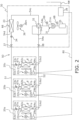
- the indoor units 20a to 20c are ceiling-embedded units installed in the ceilings.
- the indoor units 20a to 20c mainly include indoor heat exchangers 21a to 21c, indoor fans 22a to 22c, indoor expansion valves 23a to 23c, indoor control units 29a to 29c, indoor suction temperature sensors 61a to 61c, indoor heat exchange temperature sensors 62a to 62c, gas-side temperature sensors 64a to 64c, and liquid-side temperature sensors 67a to 67c. Further, as illustrated in Fig.
- the indoor units 20a to 20c include liquid refrigerant pipes 53a1 to 53c1 that connect the liquid-side ends of the indoor heat exchangers 21a to 21c and the liquid refrigerant connection pipe 51. Further, the indoor units 20a to 20c include gas refrigerant pipes 53a2 to 53c2 connecting the gas-side ends of the indoor heat exchangers 21a to 21c and the gas refrigerant connection pipe 52.
- the indoor heat exchangers 21a to 21c implement heat exchange between the refrigerant flowing through the indoor heat exchangers 21a to 21c and the air in the air-conditioning zones Z1 and Z2.
- the indoor heat exchangers 21a to 21c are, for example, fin-and-tube type heat exchangers including a plurality of heat transfer fins and a plurality of heat transfer tubes. As illustrated in Fig. 2 , one ends of the indoor heat exchangers 21a to 21c are connected to the liquid refrigerant connection pipe 51 via the liquid refrigerant pipes 53a1 to 53c1. The other ends of the indoor heat exchangers 21a to 21c are connected to the gas refrigerant connection pipe 52 via the gas refrigerant pipes 53a2 to 53c2.
- the refrigerant flows into the indoor heat exchangers 21a to 21c from the liquid refrigerant pipes 53a1 to 53c1, and the indoor heat exchangers 21a to 21c function as evaporators for the refrigerant.
- the refrigerant flows into the indoor heat exchangers 21a to 21c from the gas refrigerant pipes 53a2 to 53c2, and the indoor heat exchangers 21a to 21c function as condensers for the refrigerant.
- the indoor heat exchangers 21a to 21c are fin-and-tube heat exchangers, but are not limited thereto, and may be other types of heat exchangers.
- the indoor units 20a to 20c include the indoor fans 22a to 22c as blowers for sucking indoor air into the unit, and then supplying the air, after exchanging heat with the refrigerant in the indoor heat exchangers 21a to 21c, into the room as supplied air.
- the indoor fans 22a to 22c are fans that supply air in the air-conditioning zones Z1 and Z2 to the indoor heat exchangers 21a to 21c.
- the indoor fans 22a to 22c are, for example, centrifugal fans such as turbo fans or sirocco fans.
- the indoor fans 22a to 22c are driven by indoor fan motors 22am to 22cm including DC fan motors and the like.
- the number of rotations of the indoor fan motors 22am to 22cm can be controlled by inverters.
- the indoor expansion valves 23a to 23c are mechanisms for adjusting pressures and flow rates of the refrigerant flowing through the liquid refrigerant pipes 53a1 to 53c1.
- the indoor expansion valves 23a to 23c are provided in the liquid refrigerant pipes 53a1 to 53c1.
- the indoor expansion valves 23a to 23c are electronic expansion valves whose opening degree is adjustable.
- the indoor expansion valves 23a to 23c are provided as expansion mechanisms in the indoor units 20a to 20c, respectively.
- the present invention is not limited thereto, and the expansion mechanisms (including the expansion valves) may be provided in the outdoor unit 30, or may be provided in connection units independent of the indoor units 20a to 20c and the outdoor unit 30.
- the indoor suction temperature sensors 61a to 61c measure the temperature of the air sucked by the indoor units 20a to 20c (indoor suction temperature).
- the indoor suction temperature sensors 61a to 61c are provided near the air suction ports of the indoor units 20a to 20c.
- the indoor heat exchange temperature sensors 62a to 62c measure the temperature (indoor saturation temperature) of the refrigerant flowing through the indoor heat exchangers 21a to 21c.
- the indoor saturation temperature during the cooling operation is an evaporation temperature (indoor evaporation temperature) of the refrigerant flowing through the indoor heat exchangers 21a to 21c.
- the indoor saturation temperature during the heating operation is a condensation temperature (indoor condensation temperature) of the refrigerant flowing through the indoor heat exchangers 21a to 21c.
- the indoor heat exchange temperature sensors 62a to 62c are provided in the indoor heat exchangers 21a to 21c.
- the gas-side temperature sensors 64a to 64c measure the temperature (indoor gas-side temperature) of the refrigerant flowing through the gas refrigerant pipes 53a2 to 53c2.
- the gas-side temperature sensors 64a to 64c are provided in the gas refrigerant pipes 53a2 to 53c2.
- the liquid-side temperature sensors 67a to 67c measure the temperature (indoor liquid-side temperature) of the refrigerant flowing through the liquid refrigerant pipes 53a1 to 53c1.
- the liquid-side temperature sensors 67a to 67c are provided in the liquid refrigerant pipes 53a1 to 53c1.
- the indoor control units 29a to 29c control operations of each of units forming the indoor units 20a to 20c.
- the indoor control units 29a to 29c are electrically connected to various devices included in the indoor units 20a to 20c, including the indoor expansion valves 23a to 23c and the indoor fan motors 22am to 22cm.
- the indoor control units 29a to 29c are communicably connected to various sensors provided in the indoor units 20a to 20c, including the indoor suction temperature sensors 61a to 61c, the indoor heat exchange temperature sensors 62a to 62c, the gas-side temperature sensors 64a to 64c, and the liquid-side temperature sensors 67a to 67c.
- the indoor control units 29a to 29c include a control calculation device and a storage device.
- the control calculation device is a processor such as a CPU or a GPU.
- the storage device is a storage medium such as a RAM, a ROM, or a flash memory.
- the control calculation device reads the program stored in the storage device and executes predetermined calculation processing in accordance with the program, thereby controlling the operation of each of the units forming the indoor units 20a to 20c.
- the control calculation device can write calculation results to the storage device and read information stored in the storage device in accordance with the program.
- the indoor control units 29a to 29c include a timer.
- the indoor control units 29a to 29c are configured to be capable of receiving various signals transmitted from an operation remote controller (not illustrated).
- the various signals include, for example, signals for instructing operation start and stop, and signals related to various settings.
- the signals related to various settings include, for example, signals related to set temperature and air volume.
- the indoor control units 29a to 29c exchange control signals, measurement signals, signals related to various settings, and the like with an outdoor control unit 39 of the outdoor unit 30 via the communication line 80.
- the indoor control units 29a to 29c and the outdoor control unit 39 cooperate to function as a controller 40. The function of the controller 40 will be described below.
- the outdoor unit 30 is installed outside the building BL, such as on the roof of the building BL.
- the outdoor unit 30 mainly includes a compressor 31, a flow path switching valve 32, an outdoor heat exchanger 33, an outdoor expansion valve 34, an accumulator 35, an outdoor fan 36, a liquid-side shutoff valve 37, a gas-side shutoff valve 38, the outdoor control unit 39, an outdoor heat-exchange temperature sensor 66, a suction pressure sensor 68, and a discharge pressure sensor 69.
- the outdoor unit 30 includes a suction pipe 54a, a discharge pipe 54b, gas refrigerant pipes 54c and 54e, and a liquid refrigerant pipe 54d.
- the suction pipe 54a connects the flow path switching valve 32 and the suction side of the compressor 31.
- the suction pipe 54a is provided with the accumulator 35.
- the discharge pipe 54b connects the discharge side of the compressor 31 and the flow path switching valve 32.
- the gas refrigerant pipe 54c connects the flow path switching valve 32 and the gas side of the outdoor heat exchanger 33.
- the liquid refrigerant pipe 54d connects the liquid side of the outdoor heat exchanger 33 and the liquid refrigerant connection pipe 51.
- the liquid refrigerant pipe 54d is provided with the outdoor expansion valve 34.
- the liquid-side shutoff valve 37 is provided at a connecting portion between the liquid refrigerant pipe 54d and the liquid refrigerant connection pipe 51.
- the gas refrigerant pipe 54e connects the flow path switching valve 32 and the gas refrigerant connection pipe 52.
- the gas-side shutoff valve 38 is provided at a connecting portion between the gas refrigerant pipe 54e and the gas refrigerant connection pipe 52.
- the liquid-side shutoff valve 37 and the gas-side shutoff valve 38 are valves that are manually opened and closed.
- the compressor 31 sucks a low-pressure refrigerant from the suction pipe 54a, compresses the refrigerant by a compression mechanism (not illustrated), and discharges the compressed refrigerant to the discharge pipe 54b.
- the compressor 31 is, for example, a positive displacement compressor of a rotary type, scroll type, or the like.
- the compression mechanism of the compressor 31 is driven by a compressor motor 31m.
- the number of rotations of the compressor motor 31m can be controlled by an inverter.
- the flow path switching valve 32 is a mechanism that switches the flow path of the refrigerant between a first state and a second state.
- the flow path switching valve 32 makes the suction pipe 54a and the gas refrigerant pipe 54e communicate, and makes the discharge pipe 54b and the gas refrigerant pipe 54c communicate as indicated by a solid line in the flow path switching valve 32 in Fig. 2 .
- the flow path switching valve 32 makes the suction pipe 54a and the gas refrigerant pipe 54c communicate, and makes the discharge pipe 54b and the gas refrigerant pipe 53e communicate as indicated by a broken line in the flow path switching valve 32 in Fig. 2 .
- the flow path switching valve 32 sets the flow path of the refrigerant to the first state during the cooling operation.
- the refrigerant discharged from the compressor 31 flows through the outdoor heat exchanger 33, the outdoor expansion valve 34, the indoor expansion valves 23a to 23c, and the indoor heat exchangers 21a to 21c in this order in the refrigerant circuit 50, and returns to the compressor 31.
- the outdoor heat exchanger 33 functions as a condenser
- the indoor heat exchangers 21a to 21c function as evaporators.
- the flow path switching valve 32 sets the flow path of the refrigerant to the second state during the heating operation.
- the refrigerant discharged from the compressor 31 flows through the indoor heat exchangers 21a to 21c, the indoor expansion valves 23a to 23c, the outdoor expansion valve 34, and the outdoor heat exchanger 33 in this order in the refrigerant circuit 50, and returns to the compressor 31.
- the outdoor heat exchanger 33 functions as an evaporator
- the indoor heat exchangers 21a to 21c function as condensers.
- the outdoor heat exchanger 33 implements heat exchange between the refrigerant flowing through the outdoor heat exchanger 33 and the air outside the building BL.
- the outdoor heat exchanger 33 is, for example, a fin-and-tube heat exchanger including a plurality of heat transfer fins and a plurality of heat transfer tubes. As illustrated in Fig. 2 , one end of the outdoor heat exchanger 33 is connected to the liquid refrigerant connection pipe 51 via the liquid refrigerant pipe 54d. The other end of the outdoor heat exchanger 33 is connected to the flow path switching valve 32 via the gas refrigerant pipe 54c.
- the refrigerant flows into the outdoor heat exchanger 33 from the gas refrigerant pipe 54c, and the outdoor heat exchanger 33 functions as a condenser for the refrigerant.
- the refrigerant flows into the outdoor heat exchanger 33 from the liquid refrigerant pipe 54d, and the outdoor heat exchanger 33 functions as an evaporator for the refrigerant.
- the outdoor heat exchanger 33 is a fin-and-tube heat exchanger, but is not limited thereto, and may be other types of heat exchangers.
- the outdoor expansion valve 34 is a mechanism for adjusting the pressure and flow rate of the refrigerant flowing through the liquid refrigerant pipe 54d. As illustrated in Fig. 2 , the outdoor expansion valve 34 is provided to the liquid refrigerant pipe 54d. In the present embodiment, the outdoor expansion valve 34 is an electronic expansion valve whose opening degree is adjustable.
- the accumulator 35 is a container having a gas-liquid separation function of separating an inflowing refrigerant into a gas refrigerant and a liquid refrigerant. As illustrated in Fig. 2 , the accumulator 35 is provided to the suction pipe 54a. The refrigerant flowing into the accumulator 35 is separated into a gas refrigerant and a liquid refrigerant, and the gas refrigerant accumulated in the upper space flows into the compressor 31.
- the outdoor fan 36 is a fan that supplies air outside the building BL to the outdoor heat exchanger 33.
- the outdoor fan 36 is, for example, an axial flow fan such as a propeller fan.
- the outdoor fan 36 is driven by an outdoor fan motor 36m including a DC fan motor and the like.
- the number of rotations of the outdoor fan motor 36m can be controlled by an inverter.
- the outdoor heat-exchange temperature sensor 66 measures the temperature of the refrigerant flowing through the outdoor heat exchanger 33.
- the outdoor heat-exchange temperature sensor 66 is provided to the outdoor heat exchanger 33.
- the suction pressure sensor 68 is a sensor that measures the suction pressure of the compressor 31.
- the suction pressure sensor 68 is provided to the suction pipe 54a.
- the suction pressure is a refrigerant pressure corresponding to an evaporation pressure during the cooling operation.
- the discharge pressure sensor 69 is a sensor that measures the discharge pressure of the compressor 31.
- the discharge pressure sensor 69 is provided to the discharge pipe 54b.
- the discharge pressure is a refrigerant pressure corresponding to the condensation pressure during the heating operation.
- the outdoor control unit 39 controls the operation of each of the units forming the outdoor unit 30.
- the outdoor control unit 39 is electrically connected to the various devices of the outdoor unit 30, including the compressor motor 31m, the flow path switching valve 32, the outdoor expansion valve 34, and the outdoor fan motor 36m.
- the outdoor control unit 39 is communicably connected to various sensors provided in the outdoor unit 30, including the outdoor heat-exchange temperature sensor 66, the suction pressure sensor 68, and the discharge pressure sensor 69.
- the outdoor control unit 39 includes a control calculation device and a storage device.
- the control calculation device is a processor such as a CPU or a GPU.
- the storage device is a storage medium such as a RAM, a ROM, or a flash memory.
- the control calculation device reads the program stored in the storage device and executes predetermined calculation processing in accordance with the program, thereby controlling the operation of each of the units forming the outdoor unit 30.
- the control calculation device can write calculation results to the storage device and read information stored in the storage device in accordance with the program.
- the outdoor control unit 39 includes a timer.
- the outdoor control unit 39 exchanges control signals, measurement signals, signals related to various settings, and the like with the indoor control units 29a to 29c of the indoor units 20a to 20c via the communication line 80.
- the outdoor control unit 39 and the indoor control units 29a to 29c cooperate to function as the controller 40.
- the function of the controller 40 will be described below.
- the controller 40 includes the indoor control units 29a to 29c and the outdoor control unit 39.
- the controller 40 controls the operation of the entire air conditioner 2 by causing the respective control calculation devices of the indoor control units 29a to 29c and the outdoor control unit 39 to execute programs stored in the respective storage devices.
- the air conditioner 2 may include, as the controller 40, a centralized controller (so-called edge) that centrally controls the indoor units 20a to 20c and the outdoor unit 30.
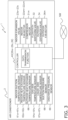
- Fig. 3 is a control block diagram of the air conditioner 2.
- the controller 40 is communicably connected to the indoor suction temperature sensors 61a to 61c, the indoor heat exchange temperature sensors 62a to 62c, the gas-side temperature sensors 64a to 64c, the liquid-side temperature sensors 67a to 67c, the outdoor heat-exchange temperature sensor 66, the suction pressure sensor 68, and the discharge pressure sensor 69.
- the controller 40 is also electrically connected to the indoor expansion valves 23a to 23c, the indoor fan motors 22am to 22cm, the compressor motor 31m, the flow path switching valve 32, the outdoor expansion valve 34, and the outdoor fan motor 36m.
- controller 40 is communicably connected to a thermal load prediction device 3 via the network NW.
- the controller 40 controls operations of various devices of the air conditioner 2 based on a control signal received from the operation remote controller via the indoor units 20a to 20c, a control signal received from the thermal load prediction device 3, measurement signals of various sensors, and the like.
- the controller 40 mainly performs the cooling operation and the heating operation.
- the controller 40 mainly has a data transmission function.
- the controller 40 switches the flow path switching valve 32 to the first state, for example, upon receiving an instruction to perform the cooling operation from the operation remote controller via the indoor unit 20a. Then, the controller 40 adjusts the number of rotations of the compressor 31, the temperature of the refrigerant flowing through the outdoor heat exchanger 33 (the temperature measured by the outdoor heat-exchange temperature sensor 66), the opening degree of the outdoor expansion valve 34, the opening degree of the indoor expansion valve 23a, and the like so that the indoor refrigerant temperature becomes the target refrigerant temperature.
- the indoor refrigerant temperature means an indoor saturation temperature (an indoor evaporation temperature during cooling operation) and a degree of superheating.
- the indoor evaporation temperature is a measured value of the indoor heat exchange temperature sensor 62a.
- the indoor evaporation temperature may be calculated from the suction pressure.
- the degree of superheating is calculated by subtracting the indoor evaporation temperature or the indoor liquid-side temperature from the indoor gas-side temperature.
- the target refrigerant temperature is set to a temperature corresponding to a set temperature received from the operation remote controller or a target refrigerant temperature received from the thermal load prediction device 3.
- the controller 40 may set the target refrigerant temperature to, for example, a temperature most recently received from the operation remote controller or the thermal load prediction device 3.
- the refrigerant flows through the refrigerant circuit 50 as follows during the cooling operation.
- the high-pressure liquid refrigerant sent to the indoor unit 20a is depressurized to have a pressure close to the suction pressure of the compressor 31 in the indoor expansion valve 23a to be a gas-liquid two-phase refrigerant, and is sent to the indoor heat exchanger 21a.
- the gas-liquid two-phase refrigerant is evaporated in the indoor heat exchanger 21a by exchanging heat with the air, in the air-conditioning zone Z1, supplied to the indoor heat exchanger 21a by the indoor fan 22a, to be low-pressure gas refrigerant.
- the low-pressure gas refrigerant is sent to the outdoor unit 30 via the gas refrigerant connection pipe 52, and flows into the accumulator 35 via the flow path switching valve 32.
- the low-pressure gas refrigerant that has flowed into the accumulator 35 is again sucked into the compressor 31.
- the temperature of the air supplied to the indoor heat exchanger 21a is lowered through heat exchange with the refrigerant flowing through the indoor heat exchanger 21a, and the air cooled by the indoor heat exchanger 21a is blown out to the air-conditioning zone Z1.
- the controller 40 switches the flow path switching valve 32 to the second state, for example, upon receiving an instruction to perform the heating operation from the operation remote controller via the indoor unit 20a. Then, the controller 40 adjusts the number of rotations of the compressor 31, the temperature of the refrigerant flowing through the outdoor heat exchanger 33, the opening degree of the outdoor expansion valve 34, the opening degree of the indoor expansion valve 23a, and the like so that the indoor refrigerant temperature becomes the target refrigerant temperature.
- the indoor refrigerant temperature means the indoor condensation temperature (the indoor condensation temperature during the heating operation) and the degree of subcooling.
- the indoor condensation temperature is a measured value of the indoor heat exchange temperature sensor 62a.
- the indoor condensation temperature may be calculated from the discharge pressure.
- the degree of subcooling is calculated by subtracting the indoor liquid-side temperature from the indoor condensation temperature or the indoor gas-side temperature.
- the target refrigerant temperature is set to a temperature corresponding to a set temperature received from the operation remote controller or a target refrigerant temperature received from the thermal load prediction device 3.
- the controller 40 may set the target refrigerant temperature to, for example, a temperature most recently received from the operation remote controller or the thermal load prediction device 3.
- the refrigerant flows through the refrigerant circuit 50 as follows during the heating operation.
- the compressor 31 When the compressor 31 is activated, low-pressure gas refrigerant is sucked into the compressor 31 and compressed by the compressor 31 to become high-pressure gas refrigerant.
- the high-pressure gas refrigerant is sent to the indoor heat exchanger 21a via the flow path switching valve 32, and is condensed by exchanging heat with the air, in the air-conditioning zone Z1, supplied to the indoor heat exchanger 21a by the indoor fan 22a, to be high-pressure liquid refrigerant.
- the temperature of the air supplied to the indoor heat exchanger 21a is raised through heat exchange with the refrigerant flowing through the indoor heat exchanger 21a, and the air heated by the indoor heat exchanger 21a is blown out to the air-conditioning zone Z1.
- the high-pressure liquid refrigerant that has passed through the indoor heat exchanger 21a is decompressed in the indoor expansion valve 23a.
- the decompressed liquid refrigerant is sent to the outdoor unit 30 via the liquid refrigerant connection pipe 51, and flows into the liquid refrigerant pipe 54d.
- the refrigerant flowing through the liquid refrigerant pipe 54d is decompressed by the outdoor expansion valve 34 to a pressure close to the suction pressure of the compressor 31, becomes a gas-liquid two-phase refrigerant, and flows into the outdoor heat exchanger 33.
- the low-pressure gas-liquid two-phase refrigerant that has flowed into the outdoor heat exchanger 33 exchanges heat with the air outside the building BL supplied by the outdoor fan 36, evaporates, and becomes low-pressure gas refrigerant.
- the low-pressure gas refrigerant flows into the accumulator 35 via the flow path switching valve 32.
- the low-pressure gas refrigerant that has flowed into the accumulator 35 is again sucked into the compressor 31.
- the controller 40 transmits operation data D3 of the air conditioner 2 to the thermal load prediction device 3.
- the controller 40 transmits the indoor suction temperature, the air volume, and the indoor refrigerant temperature (the indoor saturation temperature and the degree of superheating or degree of subcooling) of the indoor units 20a to 20c to the thermal load prediction device 3 as the operation data D3 of the air conditioner 2.
- the controller 40 acquires the indoor suction temperature of the indoor units 20a to 20c from the indoor suction temperature sensors 61a to 61c. In addition, the controller 40 acquires the air volume of the indoor units 20a to 20c based on the number of rotations of the indoor fan motors 22am to 22cm. Further, the controller 40 acquires the indoor saturation temperatures of the indoor units 20a to 20c from the indoor heat exchange temperature sensors 62a to 62c. The indoor saturation temperature may be calculated from the suction pressure or the discharge pressure. Further, the controller 40 calculates the degree of superheating by subtracting the indoor evaporation temperature or the indoor liquid-side temperature from the indoor gas-side temperature. Further, the controller 40 calculates the degree of subcooling by subtracting the indoor liquid-side temperature from the indoor condensation temperature or the indoor gas-side temperature.
- the controller 40 acquires the operation data D3 of the air conditioner 2 once in every 10 minutes and transmits the operation data D3 to the thermal load prediction device 3.
- the thermal load prediction device 3 is a computer on a cloud.
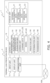
- Fig. 4 is a control block diagram of the thermal load prediction device 3. As illustrated in Fig. 4 , the thermal load prediction device 3 mainly includes a storage unit 11, an input unit 12, a display unit 13, a communication unit 14, and a control unit 19.
- the storage unit 11 is a storage device such as a RAM, a ROM, and an HDD.
- the storage unit 11 stores a program executed by the control unit 19, data necessary for the execution of the program, and the like.
- the storage unit 11 particularly stores external environmental data D1 and internal environmental data D2 acquired by an environmental data acquisition unit 191 to be described below, and the operation data D3 acquired by an operation data acquisition unit 192.
- the input unit 12 is a keyboard and a mouse. Various commands to the thermal load prediction device 3 and various types of information can be input using the input unit 12.
- the display unit 13 is a monitor.
- the display unit 13 can display various types of data and the like stored in the storage unit 11.
- the communication unit 14 is a network interface device for communicating with the air conditioner 2 and the like via the network NW.
- the control unit 19 is a processor such as a CPU or a GPU.
- the control unit 19 reads and executes a program stored in the storage unit 11 to realize various functions of the thermal load prediction device 3. In addition, according to a program, the control unit 19 can write a calculation result in the storage unit 11 or read information stored in the storage unit 11.
- control unit 19 includes, as functional blocks, the environmental data acquisition unit 191, the operation data acquisition unit 192, a learning unit 193, a prediction unit 194, a determination unit 195, and a transmission unit 196.
- the environmental data acquisition unit 191 acquires the external environmental data D1 related to the environment outside the building BL and the internal environmental data D2 related to the environment inside the building BL, both of which affect the thermal load of the air-conditioning zones Z1 and Z2.
- the external environmental data D1 includes at least the outside air temperature of the building BL.
- the external environmental data D1 is an outside air temperature of the building BL.
- the environmental data acquisition unit 191 acquires the outside air temperature of the building BL from the outdoor temperature sensor 65.
- the internal environmental data D2 includes at least the indoor temperature of the air-conditioning zones Z1 and Z2.
- the internal environmental data D2 is the indoor temperature of the air-conditioning zones Z1 and Z2.
- the environmental data acquisition unit 191 acquires the indoor temperature of the air-conditioning zones Z1 and Z2 from the indoor temperature sensors 631 and 632.
- the environmental data acquisition unit 191 acquires the external environmental data D1 and the internal environmental data D2 once in every 10 minutes.
- the external environmental data D1 and the internal environmental data D2 are used as learning data LD1 and LD2 described below.
- the operation data acquisition unit 192 acquires the operation data D3 of the air conditioner 2 from the air conditioner 2.
- the operation data D3 is the indoor suction temperature, the air volume, and the indoor refrigerant temperature of the indoor units 20a to 20c.
- the operation data acquisition unit 192 acquires the operation data D3 once in every 10 minutes at the same timing as the acquisition of the external environmental data D1 and the internal environmental data D2 by the environmental data acquisition unit 191.
- the operation data D3 is used as the learning data LD1 and LD2 described below.
- the learning unit 193 uses the learning data LD1 and LD2 obtained from the storage unit 11 to train, for each of the air-conditioning zones Z1 and Z2, of models M1 and M2 for predicting the thermal loads of the air-conditioning zones Z1 and Z2.
- the learning data LD1 and LD2 include the external environmental data D1, the internal environmental data D2, and the operation data D3.
- the learning data LD1 for the model M1 is data in which the indoor temperature of the air-conditioning zone Z1 and the outside air temperature of the building BL are associated with the thermal load of the air-conditioning zone Z1.
- the learning data LD2 for the model M2 for predicting the thermal load of the air-conditioning zone Z2 is data in which the indoor temperature of the air-conditioning zone Z2 and the outside air temperature of the building BL are associated with the thermal load of the air-conditioning zone Z2.
- the learning unit 193 trains the models M1 and M2 for predicting the thermal loads of the air-conditioning zones Z1 and Z2 from the indoor temperatures of the air-conditioning zones Z1 and Z2 and the outside air temperature of the building BL.
- the learning unit 193 calculates the thermal loads of the air-conditioning zones Z1 and Z2 in the learning data LD1 and LD2 based on the heat exchange amount in each of the indoor units 20a to 20c installed in the air-conditioning zones Z1 and Z2.
- the learning unit 193 calculates the heat exchange amount in each of the indoor units 20a to 20c based on the operation data D3.
- the learning unit 193 calculates the heat exchange amount in each of the indoor units 20a to 20c from the indoor suction temperature, the air volume, and the indoor refrigerant temperature in each of the indoor units 20a to 20c by using a predetermined relational equation holding among the heat exchange amount, the indoor suction temperature, the air volume, and the indoor refrigerant temperature in each of the indoor units 20a to 20c. Then, the learning unit 193 adds the calculated heat exchange amount in each of the indoor units 20a to 20c for each of the air-conditioning zones Z1 and Z2 in which the indoor units 20a to 20c are installed, and sets the sum as the thermal load of each of the air-conditioning zones Z1 and Z2.
- the thermal load of the air-conditioning zone Z1 is the sum of the heat exchange amount in the indoor unit 20a and the heat exchange amount in the indoor unit 20b. Further, for example, the thermal load of the air-conditioning zone Z2 is the heat exchange amount in the indoor unit 20c.
- the learning unit 193 may exclude records including missing values or abnormal values from the learning data LD1 and LD2 as preprocessing.
- the learning unit 193 may complement missing values or abnormal values included in the learning data LD1 and LD2 as preprocessing before training the models M1 and M2.
- the learning unit 193 may process the learning data LD1 and LD2 based on the operating state of the air conditioner 2 or the schedule of the air conditioner 2 as preprocessing before training the models M1 and M2.
- the models M1 and M2 are assumed to be a deep learning model.
- the deep learning model is, for example, a fully connected neural network model.
- the models M1 and M2 may be another machine learning model, may be a statistical model, may be a physical model, or may be a combination of a machine learning model, a statistical model, and a physical model.
- the models M1 and M2 may be an ensemble model or a gray box model.
- the prediction unit 194 predicts the thermal load of the air-conditioning zones Z1 and Z2 using the models M1 and M2.
- the indoor temperature 10 minutes after the data acquisition time point is predicted by using, for example, a model trained using previously acquired data in which the previously acquired indoor temperature and the indoor temperature 10 minutes after the previous acquisition are associated with each other. Further, on the assumption that the indoor temperatures of the air-conditioning zones Z1 and Z2 do not change greatly in 10 minutes, the indoor temperatures of the air-conditioning zones Z1 and Z2 acquired most recently may be used as the indoor temperatures of the air-conditioning zones Z1 and Z2 10 minutes after the data acquisition time point.
- the outside air temperature 10 minutes after the data acquisition time point is predicted by using, for example, a model trained using previously acquired data in which the outside air temperature is associated with the outside air temperature 10 minutes after the previous acquisition.
- the most recently acquired outside air temperature of the building BL may be used as the outside air temperature of the building BL 10 minutes after the data acquisition time point.
- the determination unit 195 determines a control target value or a control command value of the air conditioner 2 based on the thermal loads of the air-conditioning zones Z1 and Z2 predicted by the prediction unit 194.
- the control target value or the control command value is a target refrigerant temperature which is a target value of the indoor refrigerant temperature.
- the present invention is not limited thereto, and the control target value or the control command value may include the number of rotations of the compressor 31 or the like for achieving the target refrigerant temperature.
- the determination unit 195 performs proportional distribution to the thermal loads to be processed by the respective indoor units 20a and 20b.
- the information on the indoor units 20a and 20b may be a positional relationship between the indoor units 20a and 20b, may be a characteristic value of the indoor units 20a and 20b, may be an operating condition of the indoor units 20a and 20b, or may be information obtained by combining these.
- the determination unit 195 When the information on the indoor units 20a and 20b is the positional relationship between the indoor units 20a and 20b, the determination unit 195, for example, performs weighting in accordance with whether the positions of the indoor units 20a and 20b are in the perimeter zone or the interior zone, and proportionally distributes the predicted thermal load of the air-conditioning zone Z1 to the thermal loads processed by the indoor units 20a and 20b.
- the determination unit 195 when the information on the indoor units 20a and 20b is the operating condition of the indoor units 20a and 20b, the determination unit 195, for example, performs weighting in accordance with the respective heat exchange amounts of the indoor units 20a and 20b calculated most recently, and proportionally distributes the predicted thermal load of the air-conditioning zone Z1 to the thermal loads processed by the indoor units 20a and 20b.
- the determination unit 195 When the information on the indoor units 20a and 20b is information as a combination of the operating condition and the characteristic value of the indoor units 20a and 20b, the determination unit 195, for example, performs weighting in accordance with the magnitude of the rated capacity only for indoor units for which the start/stop state of the operation remote controller is ON, and proportionally distributes the predicted thermal load of the air-conditioning zone Z1 to the thermal loads processed by the indoor units 20a and 20b.
- the determination unit 195 calculates the thermal load to be processed by the indoor unit 20c based on the thermal load of the air-conditioning zone Z2 predicted by the prediction unit 194 and information on the indoor unit 20c installed in the air-conditioning zone Z2. For example, when the information on the indoor unit 20c is a characteristic value of the indoor unit 20c, the determination unit 195 determines the predicted thermal load of the air-conditioning zone Z2 as the thermal load processed by the indoor unit 20c within the range of the rated capacity of the indoor unit 20c.
- the determination unit 195 calculates a required refrigerant temperature in each of the indoor units 20a to 20c, which is required for each of the indoor units 20a to 20c to process the calculated thermal load. Specifically, the determination unit 195 calculates the required refrigerant temperature (indoor refrigerant temperature) in each of the indoor units 20a to 20c from the calculated thermal load (heat exchange amount), and the indoor suction temperature and the air volume 10 minutes after the data acquisition time point, using a predetermined relational equation holding among the heat exchange amount, the indoor suction temperature, the air volume, and the indoor refrigerant temperature in each of the indoor units 20a to 20c.
- the indoor suction temperature 10 minutes after the data acquisition time point is predicted by using, for example, a model trained using previously acquired data in which the indoor suction temperature is associated with the indoor suction temperature after 10 minutes. Further, assuming that the indoor suction temperature does not change greatly in 10 minutes, the indoor suction temperature acquired most recently may be used as the indoor suction temperature 10 minutes after the data acquisition time point. Further, when the indoor units 20a to 20c are in a steady state, assuming that the indoor suction temperature 10 minutes after the data acquisition time point is the most recently acquired set temperature, the most recently acquired set temperature may be used as the indoor suction temperature 10 minutes after the data acquisition time point. In this case, the operation data acquisition unit 192 acquires in advance the set temperatures of the indoor units 20a to 20c as the operation data D3.
- the air volume 10 minutes after the data acquisition time point is predicted by using, for example, a model trained using data in which the previously acquired air volume and the air volume 10 minutes after are associated with each other. Further, assuming that the setting of the air volume is not changed in 10 minutes, the most recently acquired air volume may be used as the air volume 10 minutes after the data acquisition time point.
- the determination unit 195 determines a target refrigerant temperature of the air conditioner 2 required for bringing the indoor refrigerant temperature in each of the indoor units 20a to 20c closer to the required refrigerant temperature.
- the target refrigerant temperature of the air conditioner 2 is a target refrigerant temperature common to the indoor units 20a to 20c forming the air conditioner 2.
- the determination unit 195 determines the target refrigerant temperature common to the indoor units belonging to the refrigerant system.
- the determination unit 195 determines the target refrigerant temperature of the air conditioner 2 by aggregating the required refrigerant temperatures in the indoor units 20a to 20c based on, for example, the maximum values, the minimum values, or the average values.
- the transmission unit 196 transmits the control content including the target refrigerant temperature determined by the determination unit 195 to the air conditioner 2.
- the air conditioner 2 upon receiving the target refrigerant temperature from the thermal load prediction device 3, the air conditioner 2 sets the received target refrigerant temperature as the target refrigerant temperature in the indoor units 20a to 20c.
- the air conditioner 2 maintains the set target refrigerant temperature for 10 minutes unless the set temperature or the like is changed using the operation remote controller.
- the thermal load prediction device 3 acquires the outside air temperature of the building BL (external environmental data D1) and the indoor temperature of the air-conditioning zones Z1 and Z2 (internal environmental data D2), as well as the indoor suction temperature, air volume, and indoor refrigerant temperature of the indoor units 20a to 20c (operation data D3).
- step S 1 ends, as illustrated in step S2, the thermal load prediction device 3 inputs the indoor temperature of the air-conditioning zones Z1 and Z2 and the outside air temperature of the building BL 10 minutes after the data acquisition time point to the models M1 and M2, thereby predicting the thermal loads of the air-conditioning zones Z1 and Z2 10 minutes after the data acquisition time point.
- step S3 the thermal load prediction device 3 calculates the thermal load to be processed by each of the indoor units 20a to 20c based on the predicted thermal loads of the air-conditioning zones Z1 and Z2 10 minutes after and the information on the indoor units 20a to 20c.
- step S3 ends, as illustrated in step S4, the thermal load prediction device 3 calculates a required refrigerant temperature in the indoor units 20a to 20c, which is required for processing the calculated thermal load.
- step S4 ends, as illustrated in step S5, the thermal load prediction device 3 determines a target refrigerant temperature of the air conditioner 2, which is required to bring the indoor refrigerant temperature in the indoor units 20a to 20c closer to the calculated required refrigerant temperature.
- step S5 ends, as illustrated in step S6, the thermal load prediction device 3 transmits the control content including the determined target refrigerant temperature to the air conditioner 2.
- step S6 ends, as illustrated in step S7, upon receiving the target refrigerant temperature from the thermal load prediction device 3, the air conditioner 2 sets the received target refrigerant temperature as the target refrigerant temperature in the indoor units 20a to 20c.
- the air conditioner 2 maintains the set target refrigerant temperature for 10 minutes unless the set temperature or the like is changed using the operation remote controller.
- step S7 ends, as illustrated in step S8, the thermal load prediction device 3 determines whether or not one week has elapsed since the previous training (updating) of the models M1 and M2.
- the processing proceeds to step S9.
- the processing proceeds to step S10.
- the thermal load prediction device 3 trains (updates) the models M1 and M2 for predicting the thermal loads of the air-conditioning zones Z1 and Z2 for each of the air-conditioning zones Z1 and Z2, using the learning data LD1 and LD2. In other words, the thermal load prediction device 3 trains (updates) the models M1 and M2 once a week.
- step S9 ends, or when the processing proceeds from step S8 to step S10, the thermal load prediction device 3 waits for 10 minutes.
- step S10 ends, the processing returns to step S 1, and the thermal load prediction device 3 acquires the external environmental data D1, the internal environmental data D2, and the operation data D3 again.
- the thermal load prediction device 3 acquires the external environmental data D1, the internal environmental data D2, and the operation data D3 once in every 10 minutes.
- the thermal load prediction system 1 of the present embodiment predicts the thermal loads of the air-conditioning zones Z1 and Z2 in the building BL.
- the thermal load prediction system 1 includes the environmental data acquisition unit 191, the operation data acquisition unit 192, the storage unit 11, the learning unit 193, and the prediction unit 194.
- the environmental data acquisition unit 191 acquires the external environmental data D1 related to the environment outside the building BL and the internal environmental data D2 related to the environment inside the building BL, both of which affect the thermal load of the air-conditioning zones Z1 and Z2.
- the operation data acquisition unit 192 acquires the operation data D3 of the air conditioner 2 configured to perform air conditioning for the air-conditioning zones Z1 and Z2.
- the storage unit 11 stores data acquired by the environmental data acquisition unit 191 and the operation data acquisition unit 192.
- the learning unit 193 trains the models M1 and M2 for predicting the thermal load of the air-conditioning zones Z1 and Z2 using the learning data LD1 and LD2 obtained from the storage unit 11.
- the prediction unit 194 predicts the thermal load of the air-conditioning zones Z1 and Z2 using the models M1 and M2.
- the indoor units 20a and 20b and the indoor unit 20c which form the air conditioner 2 are respectively installed.
- the thermal loads of the air-conditioning zones Z1 and Z2 in the learning data LD1 and LD2 are calculated based on the heat exchange amount in each of the indoor units 20a to 20c installed in the air-conditioning zones Z1 and Z2.
- the heat exchange amount in the indoor units 20a to 20c is calculated based on the operation data D3.
- the learning unit 193 trains the models M1 and M2 for predicting the thermal load of the air-conditioning zones Z1 and Z2 using the learning data LD1 and LD2 obtained from the storage unit 11.
- the prediction unit 194 predicts the thermal load of the air-conditioning zones Z1 and Z2 using the models M1 and M2.
- the thermal loads of the air-conditioning zones Z1 and Z2 in the learning data LD1 and LD2 are calculated based on the heat exchange amount in each of the indoor units 20a to 20c installed in the air-conditioning zones Z1 and Z2. As a result, the thermal load prediction system 1 can learn and predict the thermal load for each of the air-conditioning zones Z1 and Z2.
- the external environmental data D1 includes at least the outside air temperature of the building BL.
- the internal environmental data D2 includes at least the indoor temperature of the air-conditioning zones Z1 and Z2.
- the learning unit 193 excludes records including missing values or abnormal values from the learning data LD1 and LD2 before training the models M1 and M2.
- the learning unit 193 complements missing values or abnormal values included in the learning data LD1 and LD2 before training the models M1 and M2.
- the learning unit 193 processes the learning data LD1 and LD2 based on the operating state of the air conditioner 2 or the schedule of the air conditioner 2 before training the models M1 and M2.
- the thermal load prediction system 1 can improve the accuracy of the models M1 and M2 by excluding data that is weakly related to the thermal load of the air-conditioning zones Z1 and Z2 based on the operating state of the air conditioner 2 or the schedule of the air conditioner 2.
- the models M1 and M2 are machine learning models, statistical models, physical models, or a combination of these.
- the learning unit 193 trains the models M1 and M2 using the learning data LD1 and LD2 for the past one week (a predetermined unit).
- the learning unit 193 updates the models M1 and M2 once a week (at a predetermined timing).
- the heat exchange amount in each of the indoor units 20a to 20c is calculated based on the indoor suction temperature, the air volume, and the indoor refrigerant temperature in each of the indoor units 20a to 20c.
- the thermal load prediction system 1 of the present embodiment further includes the determination unit 195 and the transmission unit 196.
- the determination unit 195 determines the target refrigerant temperature of the air conditioner 2 based on the thermal load of the air-conditioning zones Z1 and Z2 predicted by the prediction unit 194.
- the transmission unit 196 transmits the control content including the target refrigerant temperature determined by the determination unit 195 to the air conditioner 2.
- the thermal load prediction system 1 can perform feedforward control.
- the determination unit 195 calculates the thermal load to be processed by each of the indoor units 20a to 20c based on the thermal load of the air-conditioning zones Z1 and Z2 predicted by the prediction unit 194 and the information on the indoor units 20a to 20c installed in the air-conditioning zones Z1 and Z2.
- the determination unit 195 calculates a required refrigerant temperature in each of the indoor units 20a to 20c, which is required for each of the indoor units 20a to 20c to process the calculated thermal load.
- the determination unit 195 determines a target refrigerant temperature of the air conditioner 2 required for bringing the indoor refrigerant temperature in each of the indoor units 20a to 20c closer to the required refrigerant temperature.
- the required refrigerant temperature is calculated based on the calculated thermal load (heat exchange amount), the indoor suction temperature, and the air volume in each of the indoor units 20a to 20c.
- the indoor temperature of the air-conditioning zones Z1 and Z2 is the measured value of the indoor temperature sensors 631 and 632 installed in the air-conditioning zones Z1 and Z2.
- the indoor temperature of the air-conditioning zones Z1 and Z2 may be calculated from the indoor suction temperature of the indoor units 20a to 20c.
- the indoor temperature of the air-conditioning zone Z1 can be an average value of the indoor suction temperatures of the indoor units 20a and 20b.
- the indoor temperature of the air-conditioning zone Z1 and the indoor suction temperatures of the indoor units 20a and 20b can be substituted for each other.
- the outside air temperature of the building BL is a measured value of the outdoor temperature sensor 65 installed outside the building BL.
- the outside air temperature of the building BL may be a measured value of an outdoor suction temperature sensor that measures the temperature of air sucked by the outdoor unit 30.
- the outdoor suction temperature sensor is installed in the vicinity of an air suction port of the outdoor unit 30.
- the outside air temperature of the building BL and the measured value of the outdoor suction temperature sensor can be substituted for each other.
- the thermal load prediction system 1 is applied to the plurality of air-conditioning zones Z1 and Z2 and includes a single refrigerant system.
- the thermal load prediction system 1 is applied to a system including a plurality of air-conditioning zones and a single refrigerant system.
- the thermal load prediction system 1 may be applied to a system including a single air-conditioning zone and a single refrigerant system.
- the thermal load prediction system 1 may be applied to a system including a single air-conditioning zone and a plurality of refrigerant systems, or a system including a plurality of air-conditioning zones and a plurality of refrigerant systems.
- the determination unit 195 calculates the thermal load to be processed by the indoor unit based on the thermal load of one or a plurality of air-conditioning zones predicted by the prediction unit 194 and the information on the indoor unit installed in the air-conditioning zone.
- the determination unit 195 calculates the required refrigerant temperature required for the indoor unit to process the calculated thermal load, and determines the target refrigerant temperature required for bringing the indoor refrigerant temperature in the indoor unit closer to the required refrigerant temperature for each of the plurality of refrigerant systems.
- the air conditioner 2 includes the indoor units 20a to 20c and the outdoor unit 30.
- the air conditioner 2 may further include an outside air processing air conditioner such as a humidity controller or a ventilation device.
- the learning unit 193 calculates the heat exchange amount in the humidity controller or the outside air processing air conditioner using a predetermined relational equation.
- the learning unit 193 calculates the thermal load of the air-conditioning zones Z1 and Z2 in the learning data LD1 and LD2 by adding up not only the heat exchange amounts in the indoor units 20a to 20c but also the heat exchange amounts in the humidity controller and the outside air processing air conditioner for each of the air-conditioning zones Z1 and Z2.
- the determination unit 195 proportionally distributes the thermal load of the air-conditioning zones Z1 and Z2 predicted by the prediction unit 194 to, for example, not only the thermal loads processed by the indoor units 20a to 20c but also the thermal loads processed by the humidity controller and the outside air processing air conditioner. As well as the indoor units 20a to 20c, the determination unit 195 determines respective setting values required for the humidity controller and the outside air processing air conditioner to process the calculated thermal load.
- the external environmental data D1 is the outside air temperature of the building BL.
- the external environmental data D1 may further include an amount of solar radiation of the building BL, as well as a weather forecast, an amount of cloud, a wind speed, a wind direction, an amount of precipitation, and the like at the location of the building BL.
- the environmental data acquisition unit 191 acquires the amount of solar radiation of the building BL from a solar radiation sensor installed outside the building BL.
- the prediction unit 194 predicts the amount of solar radiation 10 minutes after the data acquisition time point by using a model trained using information such as the previously acquired amount of solar radiation or the representative amount of solar radiation, and information on the weather forecast, the amount of cloud, the wind speed, the wind direction, and the amount of precipitation.
- the amount of solar radiation of the building BL does not largely change in 10 minutes
- the amount of solar radiation of the building BL acquired most recently may be used as the amount of solar radiation of the building BL 10 minutes after the data acquisition time point.
- the internal environmental data D2 is the indoor temperature of the air-conditioning zones Z1 and Z2.
- the internal environmental data D2 may further include the humidity of the air-conditioning zones Z1 and Z2, the CO2 concentration, the amount of solar radiation reaching the window/wall, the indoor temperature of the adjacent air-conditioning zone, the inflow/outflow amount of outside air, and the amount of heat generated by the OA equipment, people, and the lighting, and the like.
- the learning data LD1 and LD2 include the external environmental data D1, the internal environmental data D2, and the operation data D3.
- the thermal load prediction device 3 may further use information on the building BL and information on the air-conditioning zones Z1 and Z2, as the learning data LD1 and LD2.
- the information on the building BL is, for example, the address, the latitude and longitude, the usage, the wall thermal transmittance, and the like of the building BL.
- the information on the air-conditioning zones Z1 and Z2 is, for example, the usage of the air-conditioning zones Z1 and Z2, floor area, window area ratio, the presence or absence of window shades, ventilation type, floor height, wall length, installed equipment (number of ventilation devices installed and the like), window shading coefficient, window thermal transmittance, heat capacity of furniture and the like, and usage status (such as schedule), and the like.
- the learning unit 193 trains the models M1 and M2 using the learning data LD1 and LD2 for the air-conditioning zones Z1 and Z2, respectively.
- the learning unit 193 may train the model M1 using the learning data LD2 for the air-conditioning zone Z2 instead of the learning data LD1 for the air-conditioning zone Z1, for example.
- the learning unit 193 calculates the heat exchange amount in each of the indoor units 20a to 20c from the indoor suction temperature, the air volume, and the indoor refrigerant temperature in each of the indoor units 20a to 20c by using a predetermined relational equation holding among the heat exchange amount, the indoor suction temperature, the air volume, and the indoor refrigerant temperature in each of the indoor units 20a to 20c.
- the heat exchange amount in each of the indoor units 20a to 20c may be calculated from the indoor suction temperature, the indoor blow-out temperature, and the air volume in each of the indoor units 20a to 20c using a predetermined relational equation holding among the heat exchange amount, the indoor suction temperature, the indoor blow-out temperature, and the air volume in each of the indoor units 20a to 20c.
- the indoor blow-out temperatures of the indoor units 20a to 20c are acquired from indoor blow-out temperature sensors that measure the temperatures of the air blown out from the indoor units 20a to 20c.
- the indoor blow-out temperature sensors are provided near the air outlets of the indoor units 20a to 20c.
- the learning unit 193 may further add the indoor humidity of the air-conditioning zones Z1 and Z2 to calculate the heat exchange amounts in the respective indoor units 20a to 20c.
- the indoor humidity of the air-conditioning zones Z1 and Z2 is acquired from, for example, an indoor humidity sensor that measures the humidity of the air taken in by the indoor units 20a to 20c.
- the indoor humidity sensor is provided in the vicinity of the air inlet of the indoor units 20a to 20c.
- the determination unit 195 calculates the thermal load to be processed by each of the indoor units 20a to 20c based on the thermal loads of the plurality of air-conditioning zones Z1 and Z2 predicted by the prediction unit 194 and the information on the indoor units 20a to 20c installed in the air-conditioning zones Z1 and Z2.
- the determination unit 195 calculates the required refrigerant temperature in each of the indoor units 20a to 20c, which is required for each of the indoor units 20a to 20c to process the calculated thermal load, and determines the target refrigerant temperature of the air conditioner 2, which is required to bring the indoor refrigerant temperature in each of the indoor units 20a to 20c closer to the required refrigerant temperature.
- the determination unit 195 may aggregate the thermal loads of one or a plurality of air-conditioning zones predicted by the prediction unit 194 based on the maximum value (maximum thermal load) and determine the target refrigerant temperature of the refrigerant system required for processing the maximum thermal load.
- the determination unit 195 determines the target refrigerant temperature by using, for example, a predetermined relational equation holding among the heat exchange amount (maximum thermal load), the number of rotations of the compressor, and the target refrigerant temperature.
- the operation data acquisition unit 192 acquires in advance the number of rotations of the compressors of the refrigerant system as the operation data D3.
- the determination unit 195 may calculate the thermal load processed by the indoor unit based on the thermal load of one or a plurality of air-conditioning zones predicted by the prediction unit 194 and the information on the indoor unit installed in the air-conditioning zone, aggregate the calculated thermal loads based on the maximum value (maximum thermal load) for each of the plurality of refrigerant systems, and determine the target refrigerant temperature for each refrigerant system required for processing the aggregated maximum thermal loads for each refrigerant system.
- the learning unit 193 calculates the thermal load of the air-conditioning zones Z1 and Z2 in the learning data LD1 and LD2 by adding up the heat exchange amounts in the indoor units 20a to 20c for each of the air-conditioning zones Z1 and Z2.
- the thermal load of the air-conditioning zones Z1 and Z2 may be calculated based on the distribution of the heat exchange amount in the indoor units 20a to 20c or a value obtained by correcting the heat exchange amount in the indoor units 20a to 20c.
- the environmental data acquisition unit 191 acquires the external environmental data D1 and the internal environmental data D2.
- the environmental data acquisition unit 191 may acquire only one of the external environmental data D1 and the internal environmental data D2.
- the learning unit 193 uses only one of the external environmental data D1 and the internal environmental data D2 as the learning data piece LD1, LD2.
- the air conditioner 2 acquires the indoor saturation temperatures of the indoor units 20a to 20c from the indoor heat exchange temperature sensors 62a to 62c, and transmits the temperatures to the thermal load prediction device 3 as the operation data D3.
- the air conditioner 2 may acquire a suction pressure or a discharge pressure instead of the indoor saturation temperature and transmit the suction pressure or the discharge pressure to the thermal load prediction device 3.
- the thermal load prediction device 3 calculates the indoor saturation temperature from the suction pressure or discharge pressure acquired.
- the air conditioner 2 calculates the degree of superheating or the degree of subcooling as the operation data D3, and transmits the degree of superheating or the degree of subcooling to the thermal load prediction device 3.
- the air conditioner 2 may acquire an indoor gas-side temperature or an indoor liquid-side temperature instead of the degree of superheating or the degree of subcooling, and transmit the acquired temperature to the thermal load prediction device 3.
- the thermal load prediction device 3 calculates the degree of superheating or the degree of subcooling from the indoor gas-side temperature or indoor liquid-side temperature acquired.
- the thermal load prediction device 3 learns the indoor temperature of the air-conditioning zones Z1 and Z2 and the outside air temperature of the building BL at the same time point in association with the thermal load of the air-conditioning zones Z1 and Z2.
- the thermal load prediction device 3 may learn the indoor temperatures of the air-conditioning zones Z1 and Z2 and the outside air temperature of the building BL at a certain time point and the thermal loads of the air-conditioning zones Z1 and Z2 10 minutes after the time point in association with each other.
- the thermal load prediction device 3 can predict the thermal load of the air-conditioning zones Z1 and Z2 10 minutes after the data acquisition time point using the indoor temperatures of the air-conditioning zones Z1 and Z2 and the outside air temperature of the building BL at the data acquisition time point, without using the indoor temperatures of the air-conditioning zones Z1 and Z2 and the outside air temperature of the building BL 10 minutes after the data acquisition time point.
Landscapes
- Engineering & Computer Science (AREA)
- General Engineering & Computer Science (AREA)
- Physics & Mathematics (AREA)
- Signal Processing (AREA)
- Mathematical Physics (AREA)
- Mechanical Engineering (AREA)
- Combustion & Propulsion (AREA)
- Chemical & Material Sciences (AREA)
- Software Systems (AREA)
- Theoretical Computer Science (AREA)
- Fuzzy Systems (AREA)
- General Physics & Mathematics (AREA)
- Medical Informatics (AREA)
- Evolutionary Computation (AREA)
- Computer Vision & Pattern Recognition (AREA)
- Artificial Intelligence (AREA)
- Data Mining & Analysis (AREA)
- Computing Systems (AREA)
- Automation & Control Theory (AREA)
- Health & Medical Sciences (AREA)
- Air Conditioning Control Device (AREA)
Abstract
Description
- The present disclosure relates to a thermal load prediction system.
- As disclosed in PTL 1 (
Japanese Patent No. 5572799 - When the thermal load is learned for each outdoor unit as described in
PTL 1, there is a problem in that it is difficult to predict the thermal load for each air-conditioning zone. - A thermal load prediction system according to a first aspect predicts a thermal load of an air-conditioning zone in a building. The thermal load prediction system includes an environmental data acquisition unit, an operation data acquisition unit, a storage unit, a learning unit, and a prediction unit. The environmental data acquisition unit acquires external environmental data related to the environment outside the building and/or internal environmental data related to the environment inside the building, both of which affect the thermal load of the air-conditioning zone. The operation data acquisition unit acquires operation data of an air conditioner configured to perform air conditioning for the air-conditioning zone. The storage unit stores the data acquired by the environmental data acquisition unit and the operation data acquisition unit. The learning unit trains a model for predicting the thermal load of the air-conditioning zone using learning data obtained from the storage unit. The prediction unit predicts the thermal load of the air-conditioning zone by using the model. An indoor unit forming the air conditioner is installed in the air-conditioning zone. The thermal load of the air-conditioning zone in the learning data is calculated based on a heat exchange amount in the indoor unit installed in the air-conditioning zone. The heat exchange amount in the indoor unit is calculated based on the operation data.
- In the thermal load prediction system according to the first aspect, the learning unit trains the model for predicting the thermal load of the air-conditioning zone using the learning data obtained from the storage unit. The prediction unit predicts the thermal load of the air-conditioning zone by using the model. The thermal load of the air-conditioning zone in the learning data is calculated based on a heat exchange amount in the indoor unit installed in the air-conditioning zone. As a result, the thermal load prediction system can learn and predict the thermal load for each air-conditioning zone.
- A thermal load prediction system according to a second aspect is the thermal load prediction system according to the first aspect, in which the external environmental data includes at least an outside air temperature of the building. The internal environmental data includes at least the indoor temperature of the air-conditioning zone.
- A thermal load prediction system according to a third aspect is the thermal load prediction system according to the first aspect or the second aspect, in which the learning unit excludes a record including a missing value or an abnormal value from the learning data before training the model.
- A thermal load prediction system according to a fourth aspect is the thermal load prediction system according to the first aspect or the second aspect, in which the learning unit complements a missing value or an abnormal value included in the learning data before training the model.
- A thermal load prediction system according to a fifth aspect is the thermal load prediction system according to any one of the first aspect to the fourth aspect, in which the learning unit processes the learning data based on an operating state of the air conditioner or a schedule of the air conditioner before training the model.
- The thermal load prediction system of the fifth aspect can improve the accuracy of the model for predicting the thermal load of the air-conditioning zone by excluding data that is weakly related to the thermal load of the air-conditioning zone based on the operating state of the air conditioner or the schedule of the air conditioner.
- A thermal load prediction system according to a sixth aspect is the thermal load prediction system according to any one of the first aspect to the fifth aspect, in which the learning unit uses second learning data for a second air-conditioning zone similar to a first air-conditioning zone, instead of first learning data for the first air-conditioning zone.
- With such a configuration, the thermal load prediction system according to the sixth aspect can use common learning data for similar air-conditioning zones.
- A thermal load prediction system according to a seventh aspect is the thermal load prediction system according to any one of the first aspect to the sixth aspect, in which the model is a machine learning model, a statistical model, a physical model, or a combination of these.
- A thermal load prediction system according to an eighth aspect is the thermal load prediction system according to any one of the first aspect to the seventh aspect, in which the learning unit trains the model using learning data of a predetermined unit.
- A thermal load prediction system according to a ninth aspect is the thermal load prediction system according to any one of the first aspect to the eighth aspect, in which the learning unit updates the model at a predetermined timing.
- A thermal load prediction system according to a tenth aspect is the thermal load prediction system according to any one of the first aspect to the ninth aspect, in which the heat exchange amount in the indoor unit is calculated based on a suction temperature, an air volume, and a refrigerant temperature in the indoor unit.
- A thermal load prediction system according to an eleventh aspect is the thermal load prediction system according to any one of the first aspect to the ninth aspect, wherein the heat exchange amount in the indoor unit is calculated based on a suction temperature, a blow-out temperature, and an air volume in the indoor unit.
-
- <
Fig. 1 >Fig. 1 is a schematic configuration diagram of a thermal load prediction system. - <
Fig. 2 >Fig. 2 is a diagram illustrating a refrigerant circuit of the air conditioner. - <
Fig. 3 >Fig. 3 is a control block diagram of the air conditioner. - <
Fig. 4 >Fig. 4 is a control block diagram of the thermal load prediction device. - <
Fig. 5 >Fig. 5 is a flowchart for explaining processing executed by the thermal load prediction system. - The thermal
load prediction system 1 is a system that predicts thermal loads of air-conditioning zones Z1 and Z2 in a building BL.Fig. 1 is a schematic configuration diagram of the thermalload prediction system 1. As illustrated inFig. 1 , the thermalload prediction system 1 includes anair conditioner 2 and a thermalload prediction device 3. Theair conditioner 2 and the thermalload prediction device 3 are communicably connected via a network NW. The network NW is, for example, the Internet. - The
air conditioner 2 forms a vapor compression refrigeration cycle and performs air conditioning for the air-conditioning zones Z1 and Z2 in the building BL. In the present embodiment, theair conditioner 2 is a so-called multi-type air conditioning system for a building. As illustrated inFig. 1 , theair conditioner 2 includesindoor units 20a to 20c and anoutdoor unit 30. Theindoor units indoor unit 20c is installed in the air-conditioning zone Z2. Theindoor units 20a to 20c and theoutdoor unit 30 are communicably connected via acommunication line 80.Fig. 2 is a diagram illustrating arefrigerant circuit 50 of theair conditioner 2. As illustrating inFig. 2 , theindoor units 20a to 20c and theoutdoor unit 30 are connected by a liquidrefrigerant connection pipe 51 and a gasrefrigerant connection pipe 52 to form therefrigerant circuit 50. - The thermal
load prediction device 3 predicts the thermal loads of the air-conditioning zones Z1 and Z2 based on various types of data acquired from theair conditioner 2 and the like. - As illustrated in
Fig. 1 ,indoor temperature sensors outdoor temperature sensor 65 for measuring the outside air temperature of the building BL is installed outside the building BL. The thermalload prediction device 3, theindoor temperature sensors outdoor temperature sensor 65 are communicably connected via the network NW. - In the present embodiment, the
indoor units 20a to 20c are ceiling-embedded units installed in the ceilings. As illustrated inFig. 2 , theindoor units 20a to 20c mainly include indoor heat exchangers 21a to 21c, indoor fans 22a to 22c,indoor expansion valves 23a to 23c,indoor control units 29a to 29c, indoorsuction temperature sensors 61a to 61c, indoor heatexchange temperature sensors 62a to 62c, gas-side temperature sensors 64a to 64c, and liquid-side temperature sensors 67a to 67c. Further, as illustrated inFig. 2 , theindoor units 20a to 20c include liquid refrigerant pipes 53a1 to 53c1 that connect the liquid-side ends of the indoor heat exchangers 21a to 21c and the liquidrefrigerant connection pipe 51. Further, theindoor units 20a to 20c include gas refrigerant pipes 53a2 to 53c2 connecting the gas-side ends of the indoor heat exchangers 21a to 21c and the gasrefrigerant connection pipe 52. - The indoor heat exchangers 21a to 21c implement heat exchange between the refrigerant flowing through the indoor heat exchangers 21a to 21c and the air in the air-conditioning zones Z1 and Z2. The indoor heat exchangers 21a to 21c are, for example, fin-and-tube type heat exchangers including a plurality of heat transfer fins and a plurality of heat transfer tubes. As illustrated in
Fig. 2 , one ends of the indoor heat exchangers 21a to 21c are connected to the liquidrefrigerant connection pipe 51 via the liquid refrigerant pipes 53a1 to 53c1. The other ends of the indoor heat exchangers 21a to 21c are connected to the gasrefrigerant connection pipe 52 via the gas refrigerant pipes 53a2 to 53c2. During the cooling operation, the refrigerant flows into the indoor heat exchangers 21a to 21c from the liquid refrigerant pipes 53a1 to 53c1, and the indoor heat exchangers 21a to 21c function as evaporators for the refrigerant. During the heating operation, the refrigerant flows into the indoor heat exchangers 21a to 21c from the gas refrigerant pipes 53a2 to 53c2, and the indoor heat exchangers 21a to 21c function as condensers for the refrigerant. Note that, in the present embodiment, the indoor heat exchangers 21a to 21c are fin-and-tube heat exchangers, but are not limited thereto, and may be other types of heat exchangers. - In the present embodiment, the
indoor units 20a to 20c include the indoor fans 22a to 22c as blowers for sucking indoor air into the unit, and then supplying the air, after exchanging heat with the refrigerant in the indoor heat exchangers 21a to 21c, into the room as supplied air. The indoor fans 22a to 22c are fans that supply air in the air-conditioning zones Z1 and Z2 to the indoor heat exchangers 21a to 21c. The indoor fans 22a to 22c are, for example, centrifugal fans such as turbo fans or sirocco fans. As illustrated inFig. 2 , the indoor fans 22a to 22c are driven by indoor fan motors 22am to 22cm including DC fan motors and the like. The number of rotations of the indoor fan motors 22am to 22cm can be controlled by inverters. - The
indoor expansion valves 23a to 23c are mechanisms for adjusting pressures and flow rates of the refrigerant flowing through the liquid refrigerant pipes 53a1 to 53c1. Theindoor expansion valves 23a to 23c are provided in the liquid refrigerant pipes 53a1 to 53c1. In the present embodiment, theindoor expansion valves 23a to 23c are electronic expansion valves whose opening degree is adjustable. In the present embodiment, theindoor expansion valves 23a to 23c are provided as expansion mechanisms in theindoor units 20a to 20c, respectively. However, the present invention is not limited thereto, and the expansion mechanisms (including the expansion valves) may be provided in theoutdoor unit 30, or may be provided in connection units independent of theindoor units 20a to 20c and theoutdoor unit 30. - The indoor
suction temperature sensors 61a to 61c measure the temperature of the air sucked by theindoor units 20a to 20c (indoor suction temperature). The indoorsuction temperature sensors 61a to 61c are provided near the air suction ports of theindoor units 20a to 20c. - The indoor heat
exchange temperature sensors 62a to 62c measure the temperature (indoor saturation temperature) of the refrigerant flowing through the indoor heat exchangers 21a to 21c. The indoor saturation temperature during the cooling operation is an evaporation temperature (indoor evaporation temperature) of the refrigerant flowing through the indoor heat exchangers 21a to 21c. The indoor saturation temperature during the heating operation is a condensation temperature (indoor condensation temperature) of the refrigerant flowing through the indoor heat exchangers 21a to 21c. The indoor heatexchange temperature sensors 62a to 62c are provided in the indoor heat exchangers 21a to 21c. - The gas-
side temperature sensors 64a to 64c measure the temperature (indoor gas-side temperature) of the refrigerant flowing through the gas refrigerant pipes 53a2 to 53c2. The gas-side temperature sensors 64a to 64c are provided in the gas refrigerant pipes 53a2 to 53c2. - The liquid-
side temperature sensors 67a to 67c measure the temperature (indoor liquid-side temperature) of the refrigerant flowing through the liquid refrigerant pipes 53a1 to 53c1. The liquid-side temperature sensors 67a to 67c are provided in the liquid refrigerant pipes 53a1 to 53c1. - The
indoor control units 29a to 29c control operations of each of units forming theindoor units 20a to 20c. - The
indoor control units 29a to 29c are electrically connected to various devices included in theindoor units 20a to 20c, including theindoor expansion valves 23a to 23c and the indoor fan motors 22am to 22cm. In addition, theindoor control units 29a to 29c are communicably connected to various sensors provided in theindoor units 20a to 20c, including the indoorsuction temperature sensors 61a to 61c, the indoor heatexchange temperature sensors 62a to 62c, the gas-side temperature sensors 64a to 64c, and the liquid-side temperature sensors 67a to 67c. - The
indoor control units 29a to 29c include a control calculation device and a storage device. The control calculation device is a processor such as a CPU or a GPU. The storage device is a storage medium such as a RAM, a ROM, or a flash memory. The control calculation device reads the program stored in the storage device and executes predetermined calculation processing in accordance with the program, thereby controlling the operation of each of the units forming theindoor units 20a to 20c. In addition, the control calculation device can write calculation results to the storage device and read information stored in the storage device in accordance with the program. Theindoor control units 29a to 29c include a timer. - The
indoor control units 29a to 29c are configured to be capable of receiving various signals transmitted from an operation remote controller (not illustrated). The various signals include, for example, signals for instructing operation start and stop, and signals related to various settings. The signals related to various settings include, for example, signals related to set temperature and air volume. Theindoor control units 29a to 29c exchange control signals, measurement signals, signals related to various settings, and the like with anoutdoor control unit 39 of theoutdoor unit 30 via thecommunication line 80. Theindoor control units 29a to 29c and theoutdoor control unit 39 cooperate to function as acontroller 40. The function of thecontroller 40 will be described below. - The
outdoor unit 30 is installed outside the building BL, such as on the roof of the building BL. As illustrated inFig. 2 , theoutdoor unit 30 mainly includes acompressor 31, a flowpath switching valve 32, anoutdoor heat exchanger 33, anoutdoor expansion valve 34, anaccumulator 35, anoutdoor fan 36, a liquid-side shutoff valve 37, a gas-side shutoff valve 38, theoutdoor control unit 39, an outdoor heat-exchange temperature sensor 66, asuction pressure sensor 68, and adischarge pressure sensor 69. Theoutdoor unit 30 includes asuction pipe 54a, adischarge pipe 54b,gas refrigerant pipes refrigerant pipe 54d. - The
suction pipe 54a connects the flowpath switching valve 32 and the suction side of thecompressor 31. Thesuction pipe 54a is provided with theaccumulator 35. Thedischarge pipe 54b connects the discharge side of thecompressor 31 and the flowpath switching valve 32. Thegas refrigerant pipe 54c connects the flowpath switching valve 32 and the gas side of theoutdoor heat exchanger 33. The liquidrefrigerant pipe 54d connects the liquid side of theoutdoor heat exchanger 33 and the liquidrefrigerant connection pipe 51. The liquidrefrigerant pipe 54d is provided with theoutdoor expansion valve 34. The liquid-side shutoff valve 37 is provided at a connecting portion between the liquidrefrigerant pipe 54d and the liquidrefrigerant connection pipe 51. Thegas refrigerant pipe 54e connects the flowpath switching valve 32 and the gasrefrigerant connection pipe 52. The gas-side shutoff valve 38 is provided at a connecting portion between thegas refrigerant pipe 54e and the gasrefrigerant connection pipe 52. The liquid-side shutoff valve 37 and the gas-side shutoff valve 38 are valves that are manually opened and closed. - As illustrated in
Fig. 2 , thecompressor 31 sucks a low-pressure refrigerant from thesuction pipe 54a, compresses the refrigerant by a compression mechanism (not illustrated), and discharges the compressed refrigerant to thedischarge pipe 54b. - The
compressor 31 is, for example, a positive displacement compressor of a rotary type, scroll type, or the like. The compression mechanism of thecompressor 31 is driven by acompressor motor 31m. The number of rotations of thecompressor motor 31m can be controlled by an inverter. - The flow
path switching valve 32 is a mechanism that switches the flow path of the refrigerant between a first state and a second state. In the first state, the flowpath switching valve 32 makes thesuction pipe 54a and thegas refrigerant pipe 54e communicate, and makes thedischarge pipe 54b and thegas refrigerant pipe 54c communicate as indicated by a solid line in the flowpath switching valve 32 inFig. 2 . In the second state, the flowpath switching valve 32 makes thesuction pipe 54a and thegas refrigerant pipe 54c communicate, and makes thedischarge pipe 54b and the gas refrigerant pipe 53e communicate as indicated by a broken line in the flowpath switching valve 32 inFig. 2 . - The flow
path switching valve 32 sets the flow path of the refrigerant to the first state during the cooling operation. In this state, the refrigerant discharged from thecompressor 31 flows through theoutdoor heat exchanger 33, theoutdoor expansion valve 34, theindoor expansion valves 23a to 23c, and the indoor heat exchangers 21a to 21c in this order in therefrigerant circuit 50, and returns to thecompressor 31. In the first state, theoutdoor heat exchanger 33 functions as a condenser, and the indoor heat exchangers 21a to 21c function as evaporators. - The flow
path switching valve 32 sets the flow path of the refrigerant to the second state during the heating operation. In this state, the refrigerant discharged from thecompressor 31 flows through the indoor heat exchangers 21a to 21c, theindoor expansion valves 23a to 23c, theoutdoor expansion valve 34, and theoutdoor heat exchanger 33 in this order in therefrigerant circuit 50, and returns to thecompressor 31. In the second state, theoutdoor heat exchanger 33 functions as an evaporator, and the indoor heat exchangers 21a to 21c function as condensers. - The
outdoor heat exchanger 33 implements heat exchange between the refrigerant flowing through theoutdoor heat exchanger 33 and the air outside the building BL. Theoutdoor heat exchanger 33 is, for example, a fin-and-tube heat exchanger including a plurality of heat transfer fins and a plurality of heat transfer tubes. As illustrated inFig. 2 , one end of theoutdoor heat exchanger 33 is connected to the liquidrefrigerant connection pipe 51 via the liquidrefrigerant pipe 54d. The other end of theoutdoor heat exchanger 33 is connected to the flowpath switching valve 32 via thegas refrigerant pipe 54c. - During the cooling operation, the refrigerant flows into the
outdoor heat exchanger 33 from thegas refrigerant pipe 54c, and theoutdoor heat exchanger 33 functions as a condenser for the refrigerant. During the heating operation, the refrigerant flows into theoutdoor heat exchanger 33 from the liquidrefrigerant pipe 54d, and theoutdoor heat exchanger 33 functions as an evaporator for the refrigerant. Note that, in the present embodiment, theoutdoor heat exchanger 33 is a fin-and-tube heat exchanger, but is not limited thereto, and may be other types of heat exchangers. - The
outdoor expansion valve 34 is a mechanism for adjusting the pressure and flow rate of the refrigerant flowing through the liquidrefrigerant pipe 54d. As illustrated inFig. 2 , theoutdoor expansion valve 34 is provided to the liquidrefrigerant pipe 54d. In the present embodiment, theoutdoor expansion valve 34 is an electronic expansion valve whose opening degree is adjustable. - The
accumulator 35 is a container having a gas-liquid separation function of separating an inflowing refrigerant into a gas refrigerant and a liquid refrigerant. As illustrated inFig. 2 , theaccumulator 35 is provided to thesuction pipe 54a. The refrigerant flowing into theaccumulator 35 is separated into a gas refrigerant and a liquid refrigerant, and the gas refrigerant accumulated in the upper space flows into thecompressor 31. - The
outdoor fan 36 is a fan that supplies air outside the building BL to theoutdoor heat exchanger 33. Theoutdoor fan 36 is, for example, an axial flow fan such as a propeller fan. As illustrated inFig. 2 , theoutdoor fan 36 is driven by anoutdoor fan motor 36m including a DC fan motor and the like. The number of rotations of theoutdoor fan motor 36m can be controlled by an inverter. - The outdoor heat-
exchange temperature sensor 66 measures the temperature of the refrigerant flowing through theoutdoor heat exchanger 33. The outdoor heat-exchange temperature sensor 66 is provided to theoutdoor heat exchanger 33. - The
suction pressure sensor 68 is a sensor that measures the suction pressure of thecompressor 31. Thesuction pressure sensor 68 is provided to thesuction pipe 54a. The suction pressure is a refrigerant pressure corresponding to an evaporation pressure during the cooling operation. - The
discharge pressure sensor 69 is a sensor that measures the discharge pressure of thecompressor 31. Thedischarge pressure sensor 69 is provided to thedischarge pipe 54b. The discharge pressure is a refrigerant pressure corresponding to the condensation pressure during the heating operation. - The
outdoor control unit 39 controls the operation of each of the units forming theoutdoor unit 30. - The
outdoor control unit 39 is electrically connected to the various devices of theoutdoor unit 30, including thecompressor motor 31m, the flowpath switching valve 32, theoutdoor expansion valve 34, and theoutdoor fan motor 36m. Theoutdoor control unit 39 is communicably connected to various sensors provided in theoutdoor unit 30, including the outdoor heat-exchange temperature sensor 66, thesuction pressure sensor 68, and thedischarge pressure sensor 69. - The
outdoor control unit 39 includes a control calculation device and a storage device. The control calculation device is a processor such as a CPU or a GPU. The storage device is a storage medium such as a RAM, a ROM, or a flash memory. The control calculation device reads the program stored in the storage device and executes predetermined calculation processing in accordance with the program, thereby controlling the operation of each of the units forming theoutdoor unit 30. In addition, the control calculation device can write calculation results to the storage device and read information stored in the storage device in accordance with the program. Further, theoutdoor control unit 39 includes a timer. - The
outdoor control unit 39 exchanges control signals, measurement signals, signals related to various settings, and the like with theindoor control units 29a to 29c of theindoor units 20a to 20c via thecommunication line 80. Theoutdoor control unit 39 and theindoor control units 29a to 29c cooperate to function as thecontroller 40. The function of thecontroller 40 will be described below. - The
controller 40 includes theindoor control units 29a to 29c and theoutdoor control unit 39. Thecontroller 40 controls the operation of theentire air conditioner 2 by causing the respective control calculation devices of theindoor control units 29a to 29c and theoutdoor control unit 39 to execute programs stored in the respective storage devices. Note that theair conditioner 2 may include, as thecontroller 40, a centralized controller (so-called edge) that centrally controls theindoor units 20a to 20c and theoutdoor unit 30. -
Fig. 3 is a control block diagram of theair conditioner 2. As illustrated inFig. 3 , thecontroller 40 is communicably connected to the indoorsuction temperature sensors 61a to 61c, the indoor heatexchange temperature sensors 62a to 62c, the gas-side temperature sensors 64a to 64c, the liquid-side temperature sensors 67a to 67c, the outdoor heat-exchange temperature sensor 66, thesuction pressure sensor 68, and thedischarge pressure sensor 69. Thecontroller 40 is also electrically connected to theindoor expansion valves 23a to 23c, the indoor fan motors 22am to 22cm, thecompressor motor 31m, the flowpath switching valve 32, theoutdoor expansion valve 34, and theoutdoor fan motor 36m. Further, thecontroller 40 is communicably connected to a thermalload prediction device 3 via the network NW. Thecontroller 40 controls operations of various devices of theair conditioner 2 based on a control signal received from the operation remote controller via theindoor units 20a to 20c, a control signal received from the thermalload prediction device 3, measurement signals of various sensors, and the like. - The
controller 40 mainly performs the cooling operation and the heating operation. Thecontroller 40 mainly has a data transmission function. - Now, a case where the
controller 40 causes theindoor unit 20a to perform the cooling operation will be described. - The
controller 40 switches the flowpath switching valve 32 to the first state, for example, upon receiving an instruction to perform the cooling operation from the operation remote controller via theindoor unit 20a. Then, thecontroller 40 adjusts the number of rotations of thecompressor 31, the temperature of the refrigerant flowing through the outdoor heat exchanger 33 (the temperature measured by the outdoor heat-exchange temperature sensor 66), the opening degree of theoutdoor expansion valve 34, the opening degree of theindoor expansion valve 23a, and the like so that the indoor refrigerant temperature becomes the target refrigerant temperature. Here, the indoor refrigerant temperature means an indoor saturation temperature (an indoor evaporation temperature during cooling operation) and a degree of superheating. In the present embodiment, the indoor evaporation temperature is a measured value of the indoor heatexchange temperature sensor 62a. Alternatively, the indoor evaporation temperature may be calculated from the suction pressure. The degree of superheating is calculated by subtracting the indoor evaporation temperature or the indoor liquid-side temperature from the indoor gas-side temperature. The target refrigerant temperature is set to a temperature corresponding to a set temperature received from the operation remote controller or a target refrigerant temperature received from the thermalload prediction device 3. Thecontroller 40 may set the target refrigerant temperature to, for example, a temperature most recently received from the operation remote controller or the thermalload prediction device 3. - By controlling the operations of the various devices as described above, the refrigerant flows through the
refrigerant circuit 50 as follows during the cooling operation. - When the
compressor 31 is activated, low-pressure gas refrigerant is sucked into thecompressor 31 and compressed by thecompressor 31 to become high-pressure gas refrigerant. The high-pressure gas refrigerant is sent to theoutdoor heat exchanger 33 via the flowpath switching valve 32, exchanges heat with the air outside the building BL supplied by theoutdoor fan 36, condenses, and becomes high-pressure liquid refrigerant. The high-pressure liquid refrigerant flows through the liquidrefrigerant pipe 54d and passes through theoutdoor expansion valve 34. The high-pressure liquid refrigerant sent to theindoor unit 20a is depressurized to have a pressure close to the suction pressure of thecompressor 31 in theindoor expansion valve 23a to be a gas-liquid two-phase refrigerant, and is sent to the indoor heat exchanger 21a. The gas-liquid two-phase refrigerant is evaporated in the indoor heat exchanger 21a by exchanging heat with the air, in the air-conditioning zone Z1, supplied to the indoor heat exchanger 21a by the indoor fan 22a, to be low-pressure gas refrigerant. The low-pressure gas refrigerant is sent to theoutdoor unit 30 via the gasrefrigerant connection pipe 52, and flows into theaccumulator 35 via the flowpath switching valve 32. The low-pressure gas refrigerant that has flowed into theaccumulator 35 is again sucked into thecompressor 31. The temperature of the air supplied to the indoor heat exchanger 21a is lowered through heat exchange with the refrigerant flowing through the indoor heat exchanger 21a, and the air cooled by the indoor heat exchanger 21a is blown out to the air-conditioning zone Z1. - Here, a case where the
controller 40 causes theindoor unit 20a to perform the heating operation will be described. - The
controller 40 switches the flowpath switching valve 32 to the second state, for example, upon receiving an instruction to perform the heating operation from the operation remote controller via theindoor unit 20a. Then, thecontroller 40 adjusts the number of rotations of thecompressor 31, the temperature of the refrigerant flowing through theoutdoor heat exchanger 33, the opening degree of theoutdoor expansion valve 34, the opening degree of theindoor expansion valve 23a, and the like so that the indoor refrigerant temperature becomes the target refrigerant temperature. Here, the indoor refrigerant temperature means the indoor condensation temperature (the indoor condensation temperature during the heating operation) and the degree of subcooling. In the present embodiment, the indoor condensation temperature is a measured value of the indoor heatexchange temperature sensor 62a. Alternatively, the indoor condensation temperature may be calculated from the discharge pressure. The degree of subcooling is calculated by subtracting the indoor liquid-side temperature from the indoor condensation temperature or the indoor gas-side temperature. The target refrigerant temperature is set to a temperature corresponding to a set temperature received from the operation remote controller or a target refrigerant temperature received from the thermalload prediction device 3. Thecontroller 40 may set the target refrigerant temperature to, for example, a temperature most recently received from the operation remote controller or the thermalload prediction device 3. - By controlling the operations of the various devices as described above, the refrigerant flows through the
refrigerant circuit 50 as follows during the heating operation. - When the
compressor 31 is activated, low-pressure gas refrigerant is sucked into thecompressor 31 and compressed by thecompressor 31 to become high-pressure gas refrigerant. The high-pressure gas refrigerant is sent to the indoor heat exchanger 21a via the flowpath switching valve 32, and is condensed by exchanging heat with the air, in the air-conditioning zone Z1, supplied to the indoor heat exchanger 21a by the indoor fan 22a, to be high-pressure liquid refrigerant. The temperature of the air supplied to the indoor heat exchanger 21a is raised through heat exchange with the refrigerant flowing through the indoor heat exchanger 21a, and the air heated by the indoor heat exchanger 21a is blown out to the air-conditioning zone Z1. The high-pressure liquid refrigerant that has passed through the indoor heat exchanger 21a is decompressed in theindoor expansion valve 23a. The decompressed liquid refrigerant is sent to theoutdoor unit 30 via the liquidrefrigerant connection pipe 51, and flows into the liquidrefrigerant pipe 54d. The refrigerant flowing through the liquidrefrigerant pipe 54d is decompressed by theoutdoor expansion valve 34 to a pressure close to the suction pressure of thecompressor 31, becomes a gas-liquid two-phase refrigerant, and flows into theoutdoor heat exchanger 33. The low-pressure gas-liquid two-phase refrigerant that has flowed into theoutdoor heat exchanger 33 exchanges heat with the air outside the building BL supplied by theoutdoor fan 36, evaporates, and becomes low-pressure gas refrigerant. The low-pressure gas refrigerant flows into theaccumulator 35 via the flowpath switching valve 32. The low-pressure gas refrigerant that has flowed into theaccumulator 35 is again sucked into thecompressor 31. - The
controller 40 transmits operation data D3 of theair conditioner 2 to the thermalload prediction device 3. - In the present embodiment, the
controller 40 transmits the indoor suction temperature, the air volume, and the indoor refrigerant temperature (the indoor saturation temperature and the degree of superheating or degree of subcooling) of theindoor units 20a to 20c to the thermalload prediction device 3 as the operation data D3 of theair conditioner 2. - In the present embodiment, the
controller 40 acquires the indoor suction temperature of theindoor units 20a to 20c from the indoorsuction temperature sensors 61a to 61c. In addition, thecontroller 40 acquires the air volume of theindoor units 20a to 20c based on the number of rotations of the indoor fan motors 22am to 22cm. Further, thecontroller 40 acquires the indoor saturation temperatures of theindoor units 20a to 20c from the indoor heatexchange temperature sensors 62a to 62c. The indoor saturation temperature may be calculated from the suction pressure or the discharge pressure. Further, thecontroller 40 calculates the degree of superheating by subtracting the indoor evaporation temperature or the indoor liquid-side temperature from the indoor gas-side temperature. Further, thecontroller 40 calculates the degree of subcooling by subtracting the indoor liquid-side temperature from the indoor condensation temperature or the indoor gas-side temperature. - In the present embodiment, the
controller 40 acquires the operation data D3 of theair conditioner 2 once in every 10 minutes and transmits the operation data D3 to the thermalload prediction device 3. - The thermal
load prediction device 3 is a computer on a cloud.Fig. 4 is a control block diagram of the thermalload prediction device 3. As illustrated inFig. 4 , the thermalload prediction device 3 mainly includes astorage unit 11, aninput unit 12, adisplay unit 13, a communication unit 14, and acontrol unit 19. - The
storage unit 11 is a storage device such as a RAM, a ROM, and an HDD. Thestorage unit 11 stores a program executed by thecontrol unit 19, data necessary for the execution of the program, and the like. - In the present embodiment, the
storage unit 11 particularly stores external environmental data D1 and internal environmental data D2 acquired by an environmentaldata acquisition unit 191 to be described below, and the operation data D3 acquired by an operationdata acquisition unit 192. - The
input unit 12 is a keyboard and a mouse. Various commands to the thermalload prediction device 3 and various types of information can be input using theinput unit 12. - The
display unit 13 is a monitor. Thedisplay unit 13 can display various types of data and the like stored in thestorage unit 11. - The communication unit 14 is a network interface device for communicating with the
air conditioner 2 and the like via the network NW. - The
control unit 19 is a processor such as a CPU or a GPU. Thecontrol unit 19 reads and executes a program stored in thestorage unit 11 to realize various functions of the thermalload prediction device 3. In addition, according to a program, thecontrol unit 19 can write a calculation result in thestorage unit 11 or read information stored in thestorage unit 11. - As illustrated in
Fig. 4 , thecontrol unit 19 includes, as functional blocks, the environmentaldata acquisition unit 191, the operationdata acquisition unit 192, alearning unit 193, aprediction unit 194, adetermination unit 195, and atransmission unit 196. - The environmental
data acquisition unit 191 acquires the external environmental data D1 related to the environment outside the building BL and the internal environmental data D2 related to the environment inside the building BL, both of which affect the thermal load of the air-conditioning zones Z1 and Z2. - The external environmental data D1 includes at least the outside air temperature of the building BL. In the present embodiment, the external environmental data D1 is an outside air temperature of the building BL. The environmental
data acquisition unit 191 acquires the outside air temperature of the building BL from theoutdoor temperature sensor 65. - The internal environmental data D2 includes at least the indoor temperature of the air-conditioning zones Z1 and Z2. In the present embodiment, the internal environmental data D2 is the indoor temperature of the air-conditioning zones Z1 and Z2. The environmental
data acquisition unit 191 acquires the indoor temperature of the air-conditioning zones Z1 and Z2 from theindoor temperature sensors - In the present embodiment, the environmental
data acquisition unit 191 acquires the external environmental data D1 and the internal environmental data D2 once in every 10 minutes. - The external environmental data D1 and the internal environmental data D2 are used as learning data LD1 and LD2 described below.
- The operation
data acquisition unit 192 acquires the operation data D3 of theair conditioner 2 from theair conditioner 2. - As described above, in the present embodiment, the operation data D3 is the indoor suction temperature, the air volume, and the indoor refrigerant temperature of the
indoor units 20a to 20c. - In the present embodiment, the operation
data acquisition unit 192 acquires the operation data D3 once in every 10 minutes at the same timing as the acquisition of the external environmental data D1 and the internal environmental data D2 by the environmentaldata acquisition unit 191. - The operation data D3 is used as the learning data LD1 and LD2 described below.
- The
learning unit 193 uses the learning data LD1 and LD2 obtained from thestorage unit 11 to train, for each of the air-conditioning zones Z1 and Z2, of models M1 and M2 for predicting the thermal loads of the air-conditioning zones Z1 and Z2. - The learning data LD1 and LD2 include the external environmental data D1, the internal environmental data D2, and the operation data D3. In the present embodiment, the learning data LD1 for the model M1 is data in which the indoor temperature of the air-conditioning zone Z1 and the outside air temperature of the building BL are associated with the thermal load of the air-conditioning zone Z1. The learning data LD2 for the model M2 for predicting the thermal load of the air-conditioning zone Z2 is data in which the indoor temperature of the air-conditioning zone Z2 and the outside air temperature of the building BL are associated with the thermal load of the air-conditioning zone Z2. In other words, for each of the air-conditioning zones Z1 and Z2, the
learning unit 193 trains the models M1 and M2 for predicting the thermal loads of the air-conditioning zones Z1 and Z2 from the indoor temperatures of the air-conditioning zones Z1 and Z2 and the outside air temperature of the building BL. - The
learning unit 193 calculates the thermal loads of the air-conditioning zones Z1 and Z2 in the learning data LD1 and LD2 based on the heat exchange amount in each of theindoor units 20a to 20c installed in the air-conditioning zones Z1 and Z2. Thelearning unit 193 calculates the heat exchange amount in each of theindoor units 20a to 20c based on the operation data D3. - Specifically, first, the
learning unit 193 calculates the heat exchange amount in each of theindoor units 20a to 20c from the indoor suction temperature, the air volume, and the indoor refrigerant temperature in each of theindoor units 20a to 20c by using a predetermined relational equation holding among the heat exchange amount, the indoor suction temperature, the air volume, and the indoor refrigerant temperature in each of theindoor units 20a to 20c. Then, thelearning unit 193 adds the calculated heat exchange amount in each of theindoor units 20a to 20c for each of the air-conditioning zones Z1 and Z2 in which theindoor units 20a to 20c are installed, and sets the sum as the thermal load of each of the air-conditioning zones Z1 and Z2. For example, the thermal load of the air-conditioning zone Z1 is the sum of the heat exchange amount in theindoor unit 20a and the heat exchange amount in theindoor unit 20b. Further, for example, the thermal load of the air-conditioning zone Z2 is the heat exchange amount in theindoor unit 20c. - Before training the models M1 and M2, the
learning unit 193 may exclude records including missing values or abnormal values from the learning data LD1 and LD2 as preprocessing. Thelearning unit 193 may complement missing values or abnormal values included in the learning data LD1 and LD2 as preprocessing before training the models M1 and M2. Thelearning unit 193 may process the learning data LD1 and LD2 based on the operating state of theair conditioner 2 or the schedule of theair conditioner 2 as preprocessing before training the models M1 and M2. For example, thelearning unit 193 may exclude, from the learning data LD1 and LD2, data of operations (the oil return operation, the defrosting operation, and the like) other than the operation for controlling the indoor temperature (the cooling operation, the heating operation, and the like) , based on the operating state of theair conditioner 2. Based on the schedule of theair conditioner 2, thelearning unit 193 may exclude, for example, data such as a time zone in which theair conditioner 2 is stopped or a time zone in which theair conditioner 2 is performing a blowing operation from the learning data LD1 and LD2. - In the present embodiment, the models M1 and M2 are assumed to be a deep learning model. The deep learning model is, for example, a fully connected neural network model. However, the models M1 and M2 may be another machine learning model, may be a statistical model, may be a physical model, or may be a combination of a machine learning model, a statistical model, and a physical model. Further, the models M1 and M2 may be an ensemble model or a gray box model.
- In the present embodiment, the
learning unit 193 trains (updates) the models M1 and M2 every week by using the learning data LD1 and LD2 for the past one week. Thelearning unit 193 may perform batch learning or mini-batch learning. Further, thelearning unit 193 may train (online training) the models M1 and M2 every time the learning data LD1 and LD2 are acquired. - The
prediction unit 194 predicts the thermal load of the air-conditioning zones Z1 and Z2 using the models M1 and M2. - In the present embodiment, each time the
prediction unit 194 predicts the thermal loads of the air-conditioning zones Z1 andZ2 10 minutes after the acquisition the external environmental data D1, the internal environmental data D2, and the operation data D3, theprediction unit 194 determines a time point when the external environmental data D1, the internal environmental data D2, and the operation data D3 are acquired (hereinafter, referred to as a data acquisition time point). Specifically, theprediction unit 194 predicts the thermal loads of the air-conditioning zones Z1 andZ2 10 minutes after the data acquisition time point by inputting the indoor temperatures of the air-conditioning zones Z1 and Z2 and the outside air temperature of thebuilding BL 10 minutes after the data acquisition time point, to the models M1 and M2. - The
indoor temperature 10 minutes after the data acquisition time point is predicted by using, for example, a model trained using previously acquired data in which the previously acquired indoor temperature and theindoor temperature 10 minutes after the previous acquisition are associated with each other. Further, on the assumption that the indoor temperatures of the air-conditioning zones Z1 and Z2 do not change greatly in 10 minutes, the indoor temperatures of the air-conditioning zones Z1 and Z2 acquired most recently may be used as the indoor temperatures of the air-conditioning zones Z1 andZ2 10 minutes after the data acquisition time point. - The
outside air temperature 10 minutes after the data acquisition time point is predicted by using, for example, a model trained using previously acquired data in which the outside air temperature is associated with theoutside air temperature 10 minutes after the previous acquisition. In addition, on the assumption that the outside air temperature of the building BL does not greatly change in 10 minutes, the most recently acquired outside air temperature of the building BL may be used as the outside air temperature of thebuilding BL 10 minutes after the data acquisition time point. - The
determination unit 195 determines a control target value or a control command value of theair conditioner 2 based on the thermal loads of the air-conditioning zones Z1 and Z2 predicted by theprediction unit 194. In the present embodiment, the control target value or the control command value is a target refrigerant temperature which is a target value of the indoor refrigerant temperature. However, the present invention is not limited thereto, and the control target value or the control command value may include the number of rotations of thecompressor 31 or the like for achieving the target refrigerant temperature. - First, the
determination unit 195 calculates the thermal load to be processed by each of theindoor units 20a to 20c based on the thermal load of the air-conditioning zones Z1 and Z2 predicted by theprediction unit 194 and the information on theindoor units 20a to 20c installed in the air-conditioning zones Z1 and Z2. - For example, based on the thermal load of the air-conditioning zone Z1 predicted by the
prediction unit 194 and the information on theindoor units determination unit 195 performs proportional distribution to the thermal loads to be processed by the respectiveindoor units indoor units indoor units indoor units indoor units - When the information on the
indoor units indoor units determination unit 195, for example, performs weighting in accordance with whether the positions of theindoor units indoor units - Further, when the information on the
indoor units indoor units determination unit 195, for example, performs weighting in accordance with the magnitudes of the rated capacities of theindoor units indoor units - Further, when the information on the
indoor units indoor units determination unit 195, for example, performs weighting in accordance with the respective heat exchange amounts of theindoor units indoor units - When the information on the
indoor units indoor units determination unit 195, for example, performs weighting in accordance with the magnitude of the rated capacity only for indoor units for which the start/stop state of the operation remote controller is ON, and proportionally distributes the predicted thermal load of the air-conditioning zone Z1 to the thermal loads processed by theindoor units - Further, for example, the
determination unit 195 calculates the thermal load to be processed by theindoor unit 20c based on the thermal load of the air-conditioning zone Z2 predicted by theprediction unit 194 and information on theindoor unit 20c installed in the air-conditioning zone Z2. For example, when the information on theindoor unit 20c is a characteristic value of theindoor unit 20c, thedetermination unit 195 determines the predicted thermal load of the air-conditioning zone Z2 as the thermal load processed by theindoor unit 20c within the range of the rated capacity of theindoor unit 20c. - Next, the
determination unit 195 calculates a required refrigerant temperature in each of theindoor units 20a to 20c, which is required for each of theindoor units 20a to 20c to process the calculated thermal load. Specifically, thedetermination unit 195 calculates the required refrigerant temperature (indoor refrigerant temperature) in each of theindoor units 20a to 20c from the calculated thermal load (heat exchange amount), and the indoor suction temperature and theair volume 10 minutes after the data acquisition time point, using a predetermined relational equation holding among the heat exchange amount, the indoor suction temperature, the air volume, and the indoor refrigerant temperature in each of theindoor units 20a to 20c. - The
indoor suction temperature 10 minutes after the data acquisition time point is predicted by using, for example, a model trained using previously acquired data in which the indoor suction temperature is associated with the indoor suction temperature after 10 minutes. Further, assuming that the indoor suction temperature does not change greatly in 10 minutes, the indoor suction temperature acquired most recently may be used as theindoor suction temperature 10 minutes after the data acquisition time point. Further, when theindoor units 20a to 20c are in a steady state, assuming that theindoor suction temperature 10 minutes after the data acquisition time point is the most recently acquired set temperature, the most recently acquired set temperature may be used as theindoor suction temperature 10 minutes after the data acquisition time point. In this case, the operationdata acquisition unit 192 acquires in advance the set temperatures of theindoor units 20a to 20c as the operation data D3. - The
air volume 10 minutes after the data acquisition time point is predicted by using, for example, a model trained using data in which the previously acquired air volume and theair volume 10 minutes after are associated with each other. Further, assuming that the setting of the air volume is not changed in 10 minutes, the most recently acquired air volume may be used as theair volume 10 minutes after the data acquisition time point. - Next, the
determination unit 195 determines a target refrigerant temperature of theair conditioner 2 required for bringing the indoor refrigerant temperature in each of theindoor units 20a to 20c closer to the required refrigerant temperature. Here, the target refrigerant temperature of theair conditioner 2 is a target refrigerant temperature common to theindoor units 20a to 20c forming theair conditioner 2. In other words, thedetermination unit 195 determines the target refrigerant temperature common to the indoor units belonging to the refrigerant system. In the present embodiment, since theindoor units 20a to 20c belong to the same refrigerant system, thedetermination unit 195 determines the target refrigerant temperature of theair conditioner 2 by aggregating the required refrigerant temperatures in theindoor units 20a to 20c based on, for example, the maximum values, the minimum values, or the average values. - The
transmission unit 196 transmits the control content including the target refrigerant temperature determined by thedetermination unit 195 to theair conditioner 2. - In the present embodiment, upon receiving the target refrigerant temperature from the thermal
load prediction device 3, theair conditioner 2 sets the received target refrigerant temperature as the target refrigerant temperature in theindoor units 20a to 20c. Theair conditioner 2 maintains the set target refrigerant temperature for 10 minutes unless the set temperature or the like is changed using the operation remote controller. - An example of processing in the thermal
load prediction system 1 will be described with reference to a flowchart inFig. 5 . - As illustrated in step S1, the thermal
load prediction device 3 acquires the outside air temperature of the building BL (external environmental data D1) and the indoor temperature of the air-conditioning zones Z1 and Z2 (internal environmental data D2), as well as the indoor suction temperature, air volume, and indoor refrigerant temperature of theindoor units 20a to 20c (operation data D3). - When
step S 1 ends, as illustrated in step S2, the thermalload prediction device 3 inputs the indoor temperature of the air-conditioning zones Z1 and Z2 and the outside air temperature of thebuilding BL 10 minutes after the data acquisition time point to the models M1 and M2, thereby predicting the thermal loads of the air-conditioning zones Z1 andZ2 10 minutes after the data acquisition time point. - When step S2 ends, as illustrated in step S3, the thermal
load prediction device 3 calculates the thermal load to be processed by each of theindoor units 20a to 20c based on the predicted thermal loads of the air-conditioning zones Z1 andZ2 10 minutes after and the information on theindoor units 20a to 20c. - When step S3 ends, as illustrated in step S4, the thermal
load prediction device 3 calculates a required refrigerant temperature in theindoor units 20a to 20c, which is required for processing the calculated thermal load. - When step S4 ends, as illustrated in step S5, the thermal
load prediction device 3 determines a target refrigerant temperature of theair conditioner 2, which is required to bring the indoor refrigerant temperature in theindoor units 20a to 20c closer to the calculated required refrigerant temperature. - When step S5 ends, as illustrated in step S6, the thermal
load prediction device 3 transmits the control content including the determined target refrigerant temperature to theair conditioner 2. - When step S6 ends, as illustrated in step S7, upon receiving the target refrigerant temperature from the thermal
load prediction device 3, theair conditioner 2 sets the received target refrigerant temperature as the target refrigerant temperature in theindoor units 20a to 20c. Theair conditioner 2 maintains the set target refrigerant temperature for 10 minutes unless the set temperature or the like is changed using the operation remote controller. - When step S7 ends, as illustrated in step S8, the thermal
load prediction device 3 determines whether or not one week has elapsed since the previous training (updating) of the models M1 and M2. When one week has elapsed since the previous training (updating) of the models M1 and M2, the processing proceeds to step S9. When one week has not elapsed since the previous learning (updating) of the models M1 and M2, the processing proceeds to step S10. - When the processing proceeds from step S8 to step S9, the thermal
load prediction device 3 trains (updates) the models M1 and M2 for predicting the thermal loads of the air-conditioning zones Z1 and Z2 for each of the air-conditioning zones Z1 and Z2, using the learning data LD1 and LD2. In other words, the thermalload prediction device 3 trains (updates) the models M1 and M2 once a week. - When step S9 ends, or when the processing proceeds from step S8 to step S10, the thermal
load prediction device 3 waits for 10 minutes. - When step S10 ends, the processing returns to step
S 1, and the thermalload prediction device 3 acquires the external environmental data D1, the internal environmental data D2, and the operation data D3 again. In other words, the thermalload prediction device 3 acquires the external environmental data D1, the internal environmental data D2, and the operation data D3 once in every 10 minutes. - (4-1)
Conventionally, there has been a technique of learning and predicting a thermal load in a building. However, learning the thermal load for each outdoor unit in a conventional way involves a problem in that it is difficult to predict the thermal load for each air-conditioning zone. - The thermal
load prediction system 1 of the present embodiment predicts the thermal loads of the air-conditioning zones Z1 and Z2 in the building BL. The thermalload prediction system 1 includes the environmentaldata acquisition unit 191, the operationdata acquisition unit 192, thestorage unit 11, thelearning unit 193, and theprediction unit 194. The environmentaldata acquisition unit 191 acquires the external environmental data D1 related to the environment outside the building BL and the internal environmental data D2 related to the environment inside the building BL, both of which affect the thermal load of the air-conditioning zones Z1 and Z2. The operationdata acquisition unit 192 acquires the operation data D3 of theair conditioner 2 configured to perform air conditioning for the air-conditioning zones Z1 and Z2. Thestorage unit 11 stores data acquired by the environmentaldata acquisition unit 191 and the operationdata acquisition unit 192. Thelearning unit 193 trains the models M1 and M2 for predicting the thermal load of the air-conditioning zones Z1 and Z2 using the learning data LD1 and LD2 obtained from thestorage unit 11. Theprediction unit 194 predicts the thermal load of the air-conditioning zones Z1 and Z2 using the models M1 and M2. In the air-conditioning zones Z1 and Z2, theindoor units indoor unit 20c, which form theair conditioner 2, are respectively installed. The thermal loads of the air-conditioning zones Z1 and Z2 in the learning data LD1 and LD2 are calculated based on the heat exchange amount in each of theindoor units 20a to 20c installed in the air-conditioning zones Z1 and Z2. The heat exchange amount in theindoor units 20a to 20c is calculated based on the operation data D3. - In the thermal
load prediction system 1, thelearning unit 193 trains the models M1 and M2 for predicting the thermal load of the air-conditioning zones Z1 and Z2 using the learning data LD1 and LD2 obtained from thestorage unit 11. Theprediction unit 194 predicts the thermal load of the air-conditioning zones Z1 and Z2 using the models M1 and M2. The thermal loads of the air-conditioning zones Z1 and Z2 in the learning data LD1 and LD2 are calculated based on the heat exchange amount in each of theindoor units 20a to 20c installed in the air-conditioning zones Z1 and Z2. As a result, the thermalload prediction system 1 can learn and predict the thermal load for each of the air-conditioning zones Z1 and Z2. - (4-2)
In the thermalload prediction system 1 of the present embodiment, the external environmental data D1 includes at least the outside air temperature of the building BL. The internal environmental data D2 includes at least the indoor temperature of the air-conditioning zones Z1 and Z2. - (4-3)
In the thermalload prediction system 1 of the present embodiment, thelearning unit 193 excludes records including missing values or abnormal values from the learning data LD1 and LD2 before training the models M1 and M2. - (4-4)
In the thermalload prediction system 1 of the present embodiment, thelearning unit 193 complements missing values or abnormal values included in the learning data LD1 and LD2 before training the models M1 and M2. - (4-5)
In the thermalload prediction system 1 of the present embodiment, thelearning unit 193 processes the learning data LD1 and LD2 based on the operating state of theair conditioner 2 or the schedule of theair conditioner 2 before training the models M1 and M2. - The thermal
load prediction system 1 can improve the accuracy of the models M1 and M2 by excluding data that is weakly related to the thermal load of the air-conditioning zones Z1 and Z2 based on the operating state of theair conditioner 2 or the schedule of theair conditioner 2. - (4-6)
In the thermalload prediction system 1 of the present embodiment, the models M1 and M2 are machine learning models, statistical models, physical models, or a combination of these. - (4-7)
In the thermalload prediction system 1 of the present embodiment, thelearning unit 193 trains the models M1 and M2 using the learning data LD1 and LD2 for the past one week (a predetermined unit). - (4-8)
In the thermalload prediction system 1 of the present embodiment, thelearning unit 193 updates the models M1 and M2 once a week (at a predetermined timing). - (4-9)
In the thermalload prediction system 1 of the present embodiment, the heat exchange amount in each of theindoor units 20a to 20c is calculated based on the indoor suction temperature, the air volume, and the indoor refrigerant temperature in each of theindoor units 20a to 20c. - (4-10)
The thermalload prediction system 1 of the present embodiment further includes thedetermination unit 195 and thetransmission unit 196. Thedetermination unit 195 determines the target refrigerant temperature of theair conditioner 2 based on the thermal load of the air-conditioning zones Z1 and Z2 predicted by theprediction unit 194. Thetransmission unit 196 transmits the control content including the target refrigerant temperature determined by thedetermination unit 195 to theair conditioner 2. - As a result, the thermal
load prediction system 1 can perform feedforward control. - (4-11)
In the thermalload prediction system 1 of the present embodiment, thedetermination unit 195 calculates the thermal load to be processed by each of theindoor units 20a to 20c based on the thermal load of the air-conditioning zones Z1 and Z2 predicted by theprediction unit 194 and the information on theindoor units 20a to 20c installed in the air-conditioning zones Z1 and Z2. Thedetermination unit 195 calculates a required refrigerant temperature in each of theindoor units 20a to 20c, which is required for each of theindoor units 20a to 20c to process the calculated thermal load. Thedetermination unit 195 determines a target refrigerant temperature of theair conditioner 2 required for bringing the indoor refrigerant temperature in each of theindoor units 20a to 20c closer to the required refrigerant temperature. - (4-12)
In the thermalload prediction system 1 of the present embodiment, the required refrigerant temperature is calculated based on the calculated thermal load (heat exchange amount), the indoor suction temperature, and the air volume in each of theindoor units 20a to 20c. - In the present embodiment, the indoor temperature of the air-conditioning zones Z1 and Z2 is the measured value of the
indoor temperature sensors indoor units 20a to 20c. For example, the indoor temperature of the air-conditioning zone Z1 can be an average value of the indoor suction temperatures of theindoor units indoor units - In the present embodiment, the outside air temperature of the building BL is a measured value of the
outdoor temperature sensor 65 installed outside the building BL. Alternatively, the outside air temperature of the building BL may be a measured value of an outdoor suction temperature sensor that measures the temperature of air sucked by theoutdoor unit 30. In such a case, the outdoor suction temperature sensor is installed in the vicinity of an air suction port of theoutdoor unit 30. In other words, the outside air temperature of the building BL and the measured value of the outdoor suction temperature sensor can be substituted for each other. - In the present embodiment, the thermal
load prediction system 1 is applied to the plurality of air-conditioning zones Z1 and Z2 and includes a single refrigerant system. In other words, the thermalload prediction system 1 is applied to a system including a plurality of air-conditioning zones and a single refrigerant system. Alternatively, the thermalload prediction system 1 may be applied to a system including a single air-conditioning zone and a single refrigerant system. - Furthermore, the thermal
load prediction system 1 may be applied to a system including a single air-conditioning zone and a plurality of refrigerant systems, or a system including a plurality of air-conditioning zones and a plurality of refrigerant systems. In such a case, thedetermination unit 195 calculates the thermal load to be processed by the indoor unit based on the thermal load of one or a plurality of air-conditioning zones predicted by theprediction unit 194 and the information on the indoor unit installed in the air-conditioning zone. Thedetermination unit 195 calculates the required refrigerant temperature required for the indoor unit to process the calculated thermal load, and determines the target refrigerant temperature required for bringing the indoor refrigerant temperature in the indoor unit closer to the required refrigerant temperature for each of the plurality of refrigerant systems. - In the present embodiment, the
air conditioner 2 includes theindoor units 20a to 20c and theoutdoor unit 30. Alternatively, theair conditioner 2 may further include an outside air processing air conditioner such as a humidity controller or a ventilation device. - For example, as well as the
indoor units 20a to 20c, thelearning unit 193 calculates the heat exchange amount in the humidity controller or the outside air processing air conditioner using a predetermined relational equation. Thelearning unit 193 calculates the thermal load of the air-conditioning zones Z1 and Z2 in the learning data LD1 and LD2 by adding up not only the heat exchange amounts in theindoor units 20a to 20c but also the heat exchange amounts in the humidity controller and the outside air processing air conditioner for each of the air-conditioning zones Z1 and Z2. Thedetermination unit 195 proportionally distributes the thermal load of the air-conditioning zones Z1 and Z2 predicted by theprediction unit 194 to, for example, not only the thermal loads processed by theindoor units 20a to 20c but also the thermal loads processed by the humidity controller and the outside air processing air conditioner. As well as theindoor units 20a to 20c, thedetermination unit 195 determines respective setting values required for the humidity controller and the outside air processing air conditioner to process the calculated thermal load. - In the present embodiment, the external environmental data D1 is the outside air temperature of the building BL. Alternatively, the external environmental data D1 may further include an amount of solar radiation of the building BL, as well as a weather forecast, an amount of cloud, a wind speed, a wind direction, an amount of precipitation, and the like at the location of the building BL. For example, the environmental
data acquisition unit 191 acquires the amount of solar radiation of the building BL from a solar radiation sensor installed outside the building BL. Further, for example, theprediction unit 194 predicts the amount ofsolar radiation 10 minutes after the data acquisition time point by using a model trained using information such as the previously acquired amount of solar radiation or the representative amount of solar radiation, and information on the weather forecast, the amount of cloud, the wind speed, the wind direction, and the amount of precipitation. In addition, assuming that the amount of solar radiation of the building BL does not largely change in 10 minutes, the amount of solar radiation of the building BL acquired most recently may be used as the amount of solar radiation of thebuilding BL 10 minutes after the data acquisition time point. - In the present embodiment, the internal environmental data D2 is the indoor temperature of the air-conditioning zones Z1 and Z2. However, the internal environmental data D2 may further include the humidity of the air-conditioning zones Z1 and Z2, the CO2 concentration, the amount of solar radiation reaching the window/wall, the indoor temperature of the adjacent air-conditioning zone, the inflow/outflow amount of outside air, and the amount of heat generated by the OA equipment, people, and the lighting, and the like.
- In the present embodiment, the learning data LD1 and LD2 include the external environmental data D1, the internal environmental data D2, and the operation data D3. Alternatively, the thermal
load prediction device 3 may further use information on the building BL and information on the air-conditioning zones Z1 and Z2, as the learning data LD1 and LD2. - The information on the building BL is, for example, the address, the latitude and longitude, the usage, the wall thermal transmittance, and the like of the building BL. The information on the air-conditioning zones Z1 and Z2 is, for example, the usage of the air-conditioning zones Z1 and Z2, floor area, window area ratio, the presence or absence of window shades, ventilation type, floor height, wall length, installed equipment (number of ventilation devices installed and the like), window shading coefficient, window thermal transmittance, heat capacity of furniture and the like, and usage status (such as schedule), and the like.
- In the present embodiment, the
learning unit 193 trains the models M1 and M2 using the learning data LD1 and LD2 for the air-conditioning zones Z1 and Z2, respectively. However, when the air-conditioning zone Z1 and the air-conditioning zone Z2 are similar in terms of thermal load or the like, thelearning unit 193 may train the model M1 using the learning data LD2 for the air-conditioning zone Z2 instead of the learning data LD1 for the air-conditioning zone Z1, for example. - As a result, with the thermal
load prediction device 3, learning data can be shared between similar air-conditioning zones. - In the present embodiment, the
learning unit 193 calculates the heat exchange amount in each of theindoor units 20a to 20c from the indoor suction temperature, the air volume, and the indoor refrigerant temperature in each of theindoor units 20a to 20c by using a predetermined relational equation holding among the heat exchange amount, the indoor suction temperature, the air volume, and the indoor refrigerant temperature in each of theindoor units 20a to 20c. - Alternatively, the heat exchange amount in each of the
indoor units 20a to 20c may be calculated from the indoor suction temperature, the indoor blow-out temperature, and the air volume in each of theindoor units 20a to 20c using a predetermined relational equation holding among the heat exchange amount, the indoor suction temperature, the indoor blow-out temperature, and the air volume in each of theindoor units 20a to 20c. In this case, the indoor blow-out temperatures of theindoor units 20a to 20c are acquired from indoor blow-out temperature sensors that measure the temperatures of the air blown out from theindoor units 20a to 20c. The indoor blow-out temperature sensors are provided near the air outlets of theindoor units 20a to 20c. - In addition, the
learning unit 193 may further add the indoor humidity of the air-conditioning zones Z1 and Z2 to calculate the heat exchange amounts in the respectiveindoor units 20a to 20c. The indoor humidity of the air-conditioning zones Z1 and Z2 is acquired from, for example, an indoor humidity sensor that measures the humidity of the air taken in by theindoor units 20a to 20c. The indoor humidity sensor is provided in the vicinity of the air inlet of theindoor units 20a to 20c. As a result, thelearning unit 193 can more accurately calculate the heat exchange amount in each of theindoor units 20a to 20c. - In the present embodiment, the
determination unit 195 calculates the thermal load to be processed by each of theindoor units 20a to 20c based on the thermal loads of the plurality of air-conditioning zones Z1 and Z2 predicted by theprediction unit 194 and the information on theindoor units 20a to 20c installed in the air-conditioning zones Z1 and Z2. Thedetermination unit 195 calculates the required refrigerant temperature in each of theindoor units 20a to 20c, which is required for each of theindoor units 20a to 20c to process the calculated thermal load, and determines the target refrigerant temperature of theair conditioner 2, which is required to bring the indoor refrigerant temperature in each of theindoor units 20a to 20c closer to the required refrigerant temperature. - Alternatively, when the thermal
load prediction system 1 is applied to a system including a plurality of air-conditioning zones and a single refrigerant system (corresponding to the present embodiment) or a single air-conditioning zone and a single refrigerant system, thedetermination unit 195 may aggregate the thermal loads of one or a plurality of air-conditioning zones predicted by theprediction unit 194 based on the maximum value (maximum thermal load) and determine the target refrigerant temperature of the refrigerant system required for processing the maximum thermal load. Thedetermination unit 195 determines the target refrigerant temperature by using, for example, a predetermined relational equation holding among the heat exchange amount (maximum thermal load), the number of rotations of the compressor, and the target refrigerant temperature. In this case, the operationdata acquisition unit 192 acquires in advance the number of rotations of the compressors of the refrigerant system as the operation data D3. - When the thermal
load prediction system 1 is applied to a system including a single air-conditioning zone and a plurality of refrigerant systems or a plurality of air-conditioning zones and a plurality of refrigerant systems, thedetermination unit 195 may calculate the thermal load processed by the indoor unit based on the thermal load of one or a plurality of air-conditioning zones predicted by theprediction unit 194 and the information on the indoor unit installed in the air-conditioning zone, aggregate the calculated thermal loads based on the maximum value (maximum thermal load) for each of the plurality of refrigerant systems, and determine the target refrigerant temperature for each refrigerant system required for processing the aggregated maximum thermal loads for each refrigerant system. - In the present embodiment, the
learning unit 193 calculates the thermal load of the air-conditioning zones Z1 and Z2 in the learning data LD1 and LD2 by adding up the heat exchange amounts in theindoor units 20a to 20c for each of the air-conditioning zones Z1 and Z2. Alternatively, the thermal load of the air-conditioning zones Z1 and Z2 may be calculated based on the distribution of the heat exchange amount in theindoor units 20a to 20c or a value obtained by correcting the heat exchange amount in theindoor units 20a to 20c. - In the present embodiment, the environmental
data acquisition unit 191 acquires the external environmental data D1 and the internal environmental data D2. Alternatively, the environmentaldata acquisition unit 191 may acquire only one of the external environmental data D1 and the internal environmental data D2. - In this case, for example, the
learning unit 193 uses only one of the external environmental data D1 and the internal environmental data D2 as the learning data piece LD1, LD2. - In the present embodiment, the
air conditioner 2 acquires the indoor saturation temperatures of theindoor units 20a to 20c from the indoor heatexchange temperature sensors 62a to 62c, and transmits the temperatures to the thermalload prediction device 3 as the operation data D3. Alternatively, theair conditioner 2 may acquire a suction pressure or a discharge pressure instead of the indoor saturation temperature and transmit the suction pressure or the discharge pressure to the thermalload prediction device 3. The thermalload prediction device 3 calculates the indoor saturation temperature from the suction pressure or discharge pressure acquired. - Further, in the present embodiment, the
air conditioner 2 calculates the degree of superheating or the degree of subcooling as the operation data D3, and transmits the degree of superheating or the degree of subcooling to the thermalload prediction device 3. Alternatively, theair conditioner 2 may acquire an indoor gas-side temperature or an indoor liquid-side temperature instead of the degree of superheating or the degree of subcooling, and transmit the acquired temperature to the thermalload prediction device 3. The thermalload prediction device 3 calculates the degree of superheating or the degree of subcooling from the indoor gas-side temperature or indoor liquid-side temperature acquired. - In the present embodiment, the thermal
load prediction device 3 learns the indoor temperature of the air-conditioning zones Z1 and Z2 and the outside air temperature of the building BL at the same time point in association with the thermal load of the air-conditioning zones Z1 and Z2. Alternatively, the thermalload prediction device 3 may learn the indoor temperatures of the air-conditioning zones Z1 and Z2 and the outside air temperature of the building BL at a certain time point and the thermal loads of the air-conditioning zones Z1 andZ2 10 minutes after the time point in association with each other. - As a result, the thermal
load prediction device 3 can predict the thermal load of the air-conditioning zones Z1 andZ2 10 minutes after the data acquisition time point using the indoor temperatures of the air-conditioning zones Z1 and Z2 and the outside air temperature of the building BL at the data acquisition time point, without using the indoor temperatures of the air-conditioning zones Z1 and Z2 and the outside air temperature of thebuilding BL 10 minutes after the data acquisition time point. - (5-14)
While embodiments of the present disclosure have been described above, it should be understood that various changes in mode and detail may be made without departing from the spirit and scope of the present disclosure as set forth in the claims. -
- 1 Thermal load prediction system
- 2 Air conditioner
- 11 Storage unit
- 20a to 20c Indoor unit
- 191 Environmental data acquisition unit
- 192 Operation data acquisition unit
- 193 Learning unit
- 194 Prediction unit
- BL Building
- D1 External environmental data
- D2 Internal environmental data
- D3 Operation data
- LD1, LD2 Learning data
- M1, M2 Model
- Z1, Z2 Air-conditioning zone
- PTL 1:
Japanese Patent No. 5572799
Claims (11)
- A thermal load prediction system (1) configured to predict a thermal load of an air-conditioning zone (Z1, Z2) in a building (BL), the thermal load prediction system comprising:an environmental data acquisition unit (191) configured to acquire external environmental data (D1) related to an environment outside the building and/or internal environmental data (D2) related to an environment inside the building, both of which affect the thermal load of the air-conditioning zone;an operation data acquisition unit (192) configured to acquire operation data (D3) of an air conditioner (2) configured to perform air conditioning for the air-conditioning zone;a storage unit (11) configured to store the data acquired by the environmental data acquisition unit and the operation data acquisition unit;a learning unit (193) configured to train a model (M1, M2) with which the thermal load of the air-conditioning zone is predicted by using learning data (LD1, LD2) obtained from the storage unit; anda prediction unit (194) configured to predict the thermal load of the air-conditioning zone by using the model, whereinan indoor unit (20a to 20c) forming the air conditioner is installed in the air-conditioning zone,the thermal load of the air-conditioning zone in the learning data is calculated based on a heat exchange amount in the indoor unit installed in the air-conditioning zone, andthe heat exchange amount in the indoor unit is calculated based on the operation data.
- The thermal load prediction system (1) according to claim 1, wherein the external environmental data includes at least an outside air temperature of the building, and
the internal environmental data includes at least an indoor temperature of the air-conditioning zone. - The thermal load prediction system (1) according to claim 1 or 2, wherein the learning unit excludes a record including a missing value or an abnormal value from the learning data before training the model.
- The thermal load prediction system (1) according to claim 1 or 2, wherein the learning unit complements for a missing value or an abnormal value included in the learning data before training the model.
- The thermal load prediction system (1) according to any one of claims 1 to 4, wherein the learning unit processes the learning data based on an operating state of the air conditioner or a schedule of the air conditioner before training the model.
- The thermal load prediction system (1) according to any one of claims 1 to 5, wherein the learning unit uses second learning data for a second air-conditioning zone similar to a first air-conditioning zone instead of first learning data for the first air-conditioning zone.
- The thermal load prediction system (1) according to any one of claims 1 to 6, wherein the model is a machine learning model, a statistical model, a physical model, or a combination of these.
- The thermal load prediction system (1) according to any one of claims 1 to 7, wherein the learning unit trains the model by using the learning data of a predetermined unit.
- The thermal load prediction system (1) according to any one of claims 1 to 8, wherein the learning unit updates the model at a predetermined timing.
- The thermal load prediction system (1) according to any one of claims 1 to 9, wherein the heat exchange amount in the indoor unit is calculated based on a suction temperature, an air volume, and a refrigerant temperature in the indoor unit.
- The thermal load prediction system (1) according to any one of claims 1 to 9, wherein the heat exchange amount in the indoor unit is calculated based on a suction temperature, a blow-out temperature, and an air volume in the indoor unit.
Applications Claiming Priority (2)
| Application Number | Priority Date | Filing Date | Title |
|---|---|---|---|
| JP2022060703A JP7485970B2 (en) | 2022-03-31 | 2022-03-31 | Heat Load Prediction System |
| PCT/JP2023/011975 WO2023190229A1 (en) | 2022-03-31 | 2023-03-24 | Thermal load prediction system |
Publications (2)
| Publication Number | Publication Date |
|---|---|
| EP4502484A1 true EP4502484A1 (en) | 2025-02-05 |
| EP4502484A4 EP4502484A4 (en) | 2025-11-12 |
Family
ID=88201562
Family Applications (1)
| Application Number | Title | Priority Date | Filing Date |
|---|---|---|---|
| EP23780239.2A Pending EP4502484A4 (en) | 2022-03-31 | 2023-03-24 | THERMAL LOAD PREVENTION SYSTEM |
Country Status (5)
| Country | Link |
|---|---|
| US (1) | US20250012473A1 (en) |
| EP (1) | EP4502484A4 (en) |
| JP (2) | JP7485970B2 (en) |
| CN (1) | CN118974488A (en) |
| WO (1) | WO2023190229A1 (en) |
Family Cites Families (14)
| Publication number | Priority date | Publication date | Assignee | Title |
|---|---|---|---|---|
| JP3170507B2 (en) * | 1991-07-15 | 2001-05-28 | 東プレ株式会社 | Air conditioning equipment |
| JP2001344294A (en) * | 2000-06-01 | 2001-12-14 | Shimizu Corp | Heat transfer / air flow design support system in buildings |
| JP2002257399A (en) * | 2001-03-01 | 2002-09-11 | Denso Corp | Air conditioning system |
| JP5572799B2 (en) * | 2010-04-01 | 2014-08-20 | 三菱電機株式会社 | Air conditioning system controller |
| JP5495148B1 (en) * | 2013-06-17 | 2014-05-21 | 軍 楊 | Operation control device and operation control method |
| GB2567973B (en) * | 2016-08-24 | 2021-04-21 | Mitsubishi Electric Corp | Air-conditioning apparatus |
| JP6845784B2 (en) * | 2017-11-08 | 2021-03-24 | 株式会社東芝 | Information processing equipment, information processing methods and programs |
| JP6687043B2 (en) * | 2018-01-31 | 2020-04-22 | ダイキン工業株式会社 | Air conditioning equipment selection system |
| WO2020070794A1 (en) * | 2018-10-02 | 2020-04-09 | 三菱電機株式会社 | Information processing device and air-conditioning system provided with same |
| JP2020139705A (en) * | 2019-02-28 | 2020-09-03 | 富士通株式会社 | Operation control method, operation control program and operation control device |
| JP7112037B2 (en) * | 2019-06-24 | 2022-08-03 | 三菱電機株式会社 | Air conditioners and air conditioning systems |
| KR20210063968A (en) * | 2019-11-25 | 2021-06-02 | 엘지전자 주식회사 | Refrigerator operating method |
| CN111932015B (en) * | 2020-08-12 | 2023-06-16 | 武汉中电节能有限公司 | Prediction method and system for regional cooling and heating cold and heat load |
| WO2023120271A1 (en) * | 2021-12-20 | 2023-06-29 | 株式会社デンソー | Heat pump system |
-
2022
- 2022-03-31 JP JP2022060703A patent/JP7485970B2/en active Active
-
2023
- 2023-03-24 CN CN202380031578.0A patent/CN118974488A/en active Pending
- 2023-03-24 EP EP23780239.2A patent/EP4502484A4/en active Pending
- 2023-03-24 WO PCT/JP2023/011975 patent/WO2023190229A1/en not_active Ceased
-
2024
- 2024-02-13 JP JP2024019712A patent/JP2024040385A/en active Pending
- 2024-09-18 US US18/889,240 patent/US20250012473A1/en active Pending
Also Published As
| Publication number | Publication date |
|---|---|
| CN118974488A (en) | 2024-11-15 |
| JP2024040385A (en) | 2024-03-25 |
| WO2023190229A1 (en) | 2023-10-05 |
| EP4502484A4 (en) | 2025-11-12 |
| JP2023151213A (en) | 2023-10-16 |
| JP7485970B2 (en) | 2024-05-17 |
| US20250012473A1 (en) | 2025-01-09 |
Similar Documents
| Publication | Publication Date | Title |
|---|---|---|
| US8660702B2 (en) | Central cooling and circulation energy management control system | |
| EP3859247B1 (en) | Air-conditioning device | |
| EP2729737B1 (en) | Methods and apparatus for differential energy based airside economizer changeover | |
| JP6739671B1 (en) | Information processing equipment | |
| KR20110104054A (en) | Load Handling Balance Setting Device | |
| EP4116635B1 (en) | Air conditioner | |
| JP6486547B2 (en) | Air conditioning system | |
| WO2016158938A1 (en) | Air conditioner | |
| EP3093568A1 (en) | Ventilation device | |
| JP2024069174A (en) | Air conditioning system control device | |
| TWI604160B (en) | Operation control device and operation control method | |
| JP2005301582A (en) | Process management device | |
| US20240003579A1 (en) | Air conditioning control apparatus and air conditioning system | |
| EP3943824A1 (en) | Device evaluation system and device evaluation method | |
| US20250012473A1 (en) | Thermal load prediction system | |
| JP7278065B2 (en) | refrigeration cycle equipment | |
| EP4336116B1 (en) | Air-conditioning device | |
| WO2020003529A1 (en) | Air conditioning system, air conditioning method, and program | |
| EP4116633A1 (en) | Air conditioner | |
| JP7787481B1 (en) | Equipment selection method and equipment selection system | |
| JP7817602B2 (en) | Air conditioning zoning method | |
| EP4382829A1 (en) | Refrigeration cycle device | |
| KR100988617B1 (en) | Air Conditioner and Control Method | |
| JP7383154B2 (en) | Air conditioning monitoring equipment and air conditioning systems | |
| WO2025173676A1 (en) | Failure diagnosis assistance device and failure diagnosis assistance method |
Legal Events
| Date | Code | Title | Description |
|---|---|---|---|
| STAA | Information on the status of an ep patent application or granted ep patent |
Free format text: STATUS: THE INTERNATIONAL PUBLICATION HAS BEEN MADE |
|
| PUAI | Public reference made under article 153(3) epc to a published international application that has entered the european phase |
Free format text: ORIGINAL CODE: 0009012 |
|
| STAA | Information on the status of an ep patent application or granted ep patent |
Free format text: STATUS: REQUEST FOR EXAMINATION WAS MADE |
|
| 17P | Request for examination filed |
Effective date: 20241024 |
|
| AK | Designated contracting states |
Kind code of ref document: A1 Designated state(s): AL AT BE BG CH CY CZ DE DK EE ES FI FR GB GR HR HU IE IS IT LI LT LU LV MC ME MK MT NL NO PL PT RO RS SE SI SK SM TR |
|
| REG | Reference to a national code |
Ref country code: DE Ref legal event code: R079 Free format text: PREVIOUS MAIN CLASS: F24F0011640000 Ipc: G05B0015020000 |
|
| DAV | Request for validation of the european patent (deleted) | ||
| DAX | Request for extension of the european patent (deleted) | ||
| RIC1 | Information provided on ipc code assigned before grant |
Ipc: G05B 15/02 20060101AFI20250626BHEP Ipc: F24F 11/64 20180101ALI20250626BHEP Ipc: F24F 110/00 20180101ALI20250626BHEP Ipc: F24F 110/12 20180101ALI20250626BHEP Ipc: G05B 13/04 20060101ALI20250626BHEP Ipc: F24F 11/46 20180101ALI20250626BHEP Ipc: F24F 11/62 20180101ALI20250626BHEP Ipc: F24F 11/63 20180101ALI20250626BHEP Ipc: G06N 20/00 20190101ALI20250626BHEP Ipc: F24F 11/30 20180101ALI20250626BHEP |
|
| P01 | Opt-out of the competence of the unified patent court (upc) registered |
Free format text: CASE NUMBER: UPC_APP_3799_4502484/2025 Effective date: 20250820 |
|
| A4 | Supplementary search report drawn up and despatched |
Effective date: 20251015 |
|
| RIC1 | Information provided on ipc code assigned before grant |
Ipc: G05B 15/02 20060101AFI20251009BHEP Ipc: F24F 11/64 20180101ALI20251009BHEP Ipc: F24F 110/00 20180101ALI20251009BHEP Ipc: F24F 110/12 20180101ALI20251009BHEP Ipc: G05B 13/04 20060101ALI20251009BHEP Ipc: F24F 11/46 20180101ALI20251009BHEP Ipc: F24F 11/62 20180101ALI20251009BHEP Ipc: F24F 11/63 20180101ALI20251009BHEP Ipc: G06N 20/00 20190101ALI20251009BHEP Ipc: F24F 11/30 20180101ALI20251009BHEP |
|
| GRAP | Despatch of communication of intention to grant a patent |
Free format text: ORIGINAL CODE: EPIDOSNIGR1 |
|
| STAA | Information on the status of an ep patent application or granted ep patent |
Free format text: STATUS: GRANT OF PATENT IS INTENDED |
|
| INTG | Intention to grant announced |
Effective date: 20260630 |
|
| GRAS | Grant fee paid |
Free format text: ORIGINAL CODE: EPIDOSNIGR3 |
|
| GRAA | (expected) grant |
Free format text: ORIGINAL CODE: 0009210 |
|
| STAA | Information on the status of an ep patent application or granted ep patent |
Free format text: STATUS: THE PATENT HAS BEEN GRANTED |