EP4502478A1 - Heat pump device - Google Patents
Heat pump device Download PDFInfo
- Publication number
- EP4502478A1 EP4502478A1 EP23780583.3A EP23780583A EP4502478A1 EP 4502478 A1 EP4502478 A1 EP 4502478A1 EP 23780583 A EP23780583 A EP 23780583A EP 4502478 A1 EP4502478 A1 EP 4502478A1
- Authority
- EP
- European Patent Office
- Prior art keywords
- terminal
- forced convection
- heated water
- temperature
- source equipment
- Prior art date
- Legal status (The legal status is an assumption and is not a legal conclusion. Google has not performed a legal analysis and makes no representation as to the accuracy of the status listed.)
- Pending
Links
Images

Classifications
-
- F—MECHANICAL ENGINEERING; LIGHTING; HEATING; WEAPONS; BLASTING
- F24—HEATING; RANGES; VENTILATING
- F24D—DOMESTIC- OR SPACE-HEATING SYSTEMS, e.g. CENTRAL HEATING SYSTEMS; DOMESTIC HOT-WATER SUPPLY SYSTEMS; ELEMENTS OR COMPONENTS THEREFOR
- F24D3/00—Hot-water central heating systems
- F24D3/18—Hot-water central heating systems using heat pumps
-
- F—MECHANICAL ENGINEERING; LIGHTING; HEATING; WEAPONS; BLASTING
- F24—HEATING; RANGES; VENTILATING
- F24D—DOMESTIC- OR SPACE-HEATING SYSTEMS, e.g. CENTRAL HEATING SYSTEMS; DOMESTIC HOT-WATER SUPPLY SYSTEMS; ELEMENTS OR COMPONENTS THEREFOR
- F24D19/00—Details
- F24D19/10—Arrangement or mounting of control or safety devices
- F24D19/1006—Arrangement or mounting of control or safety devices for water heating systems
- F24D19/1009—Arrangement or mounting of control or safety devices for water heating systems for central heating
- F24D19/1039—Arrangement or mounting of control or safety devices for water heating systems for central heating the system uses a heat pump
-
- F—MECHANICAL ENGINEERING; LIGHTING; HEATING; WEAPONS; BLASTING
- F24—HEATING; RANGES; VENTILATING
- F24F—AIR-CONDITIONING; AIR-HUMIDIFICATION; VENTILATION; USE OF AIR CURRENTS FOR SCREENING
- F24F11/00—Control or safety arrangements
- F24F11/70—Control systems characterised by their outputs; Constructional details thereof
- F24F11/72—Control systems characterised by their outputs; Constructional details thereof for controlling the supply of treated air, e.g. its pressure
- F24F11/74—Control systems characterised by their outputs; Constructional details thereof for controlling the supply of treated air, e.g. its pressure for controlling air flow rate or air velocity
-
- F—MECHANICAL ENGINEERING; LIGHTING; HEATING; WEAPONS; BLASTING
- F24—HEATING; RANGES; VENTILATING
- F24H—FLUID HEATERS, e.g. WATER OR AIR HEATERS, HAVING HEAT-GENERATING MEANS, e.g. HEAT PUMPS, IN GENERAL
- F24H15/00—Control of fluid heaters
- F24H15/10—Control of fluid heaters characterised by the purpose of the control
- F24H15/176—Improving or maintaining comfort of users
-
- F—MECHANICAL ENGINEERING; LIGHTING; HEATING; WEAPONS; BLASTING
- F24—HEATING; RANGES; VENTILATING
- F24H—FLUID HEATERS, e.g. WATER OR AIR HEATERS, HAVING HEAT-GENERATING MEANS, e.g. HEAT PUMPS, IN GENERAL
- F24H15/00—Control of fluid heaters
- F24H15/20—Control of fluid heaters characterised by control inputs
- F24H15/212—Temperature of the water
- F24H15/219—Temperature of the water after heating
-
- F—MECHANICAL ENGINEERING; LIGHTING; HEATING; WEAPONS; BLASTING
- F24—HEATING; RANGES; VENTILATING
- F24H—FLUID HEATERS, e.g. WATER OR AIR HEATERS, HAVING HEAT-GENERATING MEANS, e.g. HEAT PUMPS, IN GENERAL
- F24H15/00—Control of fluid heaters
- F24H15/20—Control of fluid heaters characterised by control inputs
- F24H15/254—Room temperature
-
- F—MECHANICAL ENGINEERING; LIGHTING; HEATING; WEAPONS; BLASTING
- F24—HEATING; RANGES; VENTILATING
- F24H—FLUID HEATERS, e.g. WATER OR AIR HEATERS, HAVING HEAT-GENERATING MEANS, e.g. HEAT PUMPS, IN GENERAL
- F24H15/00—Control of fluid heaters
- F24H15/30—Control of fluid heaters characterised by control outputs; characterised by the components to be controlled
- F24H15/345—Control of fans, e.g. on-off control
- F24H15/35—Control of the speed of fans
-
- F—MECHANICAL ENGINEERING; LIGHTING; HEATING; WEAPONS; BLASTING
- F24—HEATING; RANGES; VENTILATING
- F24H—FLUID HEATERS, e.g. WATER OR AIR HEATERS, HAVING HEAT-GENERATING MEANS, e.g. HEAT PUMPS, IN GENERAL
- F24H15/00—Control of fluid heaters
- F24H15/30—Control of fluid heaters characterised by control outputs; characterised by the components to be controlled
- F24H15/375—Control of heat pumps
-
- F—MECHANICAL ENGINEERING; LIGHTING; HEATING; WEAPONS; BLASTING
- F24—HEATING; RANGES; VENTILATING
- F24D—DOMESTIC- OR SPACE-HEATING SYSTEMS, e.g. CENTRAL HEATING SYSTEMS; DOMESTIC HOT-WATER SUPPLY SYSTEMS; ELEMENTS OR COMPONENTS THEREFOR
- F24D19/00—Details
- F24D19/008—Details related to central heating radiators
- F24D19/0087—Fan arrangements for forced convection
-
- F—MECHANICAL ENGINEERING; LIGHTING; HEATING; WEAPONS; BLASTING
- F24—HEATING; RANGES; VENTILATING
- F24D—DOMESTIC- OR SPACE-HEATING SYSTEMS, e.g. CENTRAL HEATING SYSTEMS; DOMESTIC HOT-WATER SUPPLY SYSTEMS; ELEMENTS OR COMPONENTS THEREFOR
- F24D2200/00—Heat sources or energy sources
- F24D2200/12—Heat pump
- F24D2200/123—Compression type heat pumps
Definitions
- the present invention relates to a heat pump device.
- a heat pump device that flows heated water that is produced by heat source equipment to an indoor terminal to warm an indoor space in which the indoor terminal is set is known.
- the indoor terminal for example, a forced convection terminal that adjusts an indoor temperature by forced convection from the indoor terminal and a radiation terminal that adjusts the indoor temperature by radiant heat of the heated water that passes through the indoor terminal.
- Patent Literature 1 Japanese Laid-open Patent Publication No. 2019-70498
- an object of the present invention is to provide a heat pump device that makes it possible to inhibit comfortableness to a user from lowering.
- the heat pump device includes a heat source equipment, a radiation terminal, a forced convection terminal and a control device.
- the heat source equipment produces heated water by a heat source.
- the radiation terminal is connected to the heat source equipment and adjusts a temperature of an indoor space by radiation heat that is obtained by flowing the heated water from the heat source equipment into a radiation panel.
- the forced convection terminal is connected to the heat source equipment, flows the heated water from the heat source equipment into a use-side heat exchanger, and blows air on which heat exchange with the heated water is performed by the use-side heat exchanger using a blast fan and thus adjusts the temperature of the indoor space.
- the control device controls the heat source equipment, the radiation terminal, and the forced convection terminal.
- the control device includes a controller that, when the radiation terminal and the forced convection terminal are operated at a time, controls the forced convection terminal to reduce an air volume of the forced convection terminal compared to an air volume in a case where only the forced convection terminal is in operation.
- FIG. 1 is an illustration illustrating an example of a heat pump device 1 of the present embodiment.
- the heat pump device 1 illustrated in FIG. 1 includes heat source equipment 2 that produces heated water, a use-side terminal group 3 including a plurality of use-side terminals 4, and a control device 5 that controls the entire heat pump device 1.
- the heat source equipment 2 includes a heat source 20 that produces heated water.
- the heat source 20 includes a refrigerant line 21 ad a water line 22.
- the refrigerant line 21 is, for example, a line in which a refrigerant circulates inside with a compressor and that performs heat exchange between the refrigerant that circulates and external air.
- water line 22 for example, water circulates inside and the water line 22 causes heat exchange between the water circulating inside and the refrigerant circulating in the refrigerant line 21, thereby producing heated water.
- the water line 22, for example flows the heated water into the use-side terminal group 3 using a circulation pump, thereby adjusting the temperature of the indoor space in which the use-side terminal 4 of the use-side terminal group 3 is arranged.
- the use-side terminal group 3 includes the use-side terminals 4, a branch pipe 31 and a merging pipe 32.
- the use-side terminals 4 that are set in the indoor space, for example, a radiation terminal 4A, a forced convection terminal 4B, etc.
- the radiation terminal 4A is, for example, a floor heating terminal and includes a radiation panel 41A that is an use-side heat exchanger 41, is connected to the water line 22 in the heat source equipment 2, and adjusts the temperature of the indoor space using the radiant heat obtained by flowing the heated water from the water line 22 into the radiation panel 41A.
- the forced convection terminal 4B includes a use-side heat exchanger 41B (41), a blower fan 42, a fan controller 43, and a temperature sensor 44.
- the use-side heat exchanger 41B is connected to the water line 22 in the heat source equipment 2, the heated water flows from the water line 22 into the use-side heat exchanger 41B, and the blower fan 42 blows the air on which heat exchange with the heated water is performed by the use-side heat exchanger 41B into the indoor space, thereby adjusting the temperature of the indoor space.
- the blower fan 42 is a fan that generates forced convection.
- the fan controller 43 adjusts the air volume by controlling the rotation rate of the blower fan 42.
- the temperature sensor 44 is a sensor that is arranged at the inlet of the use-side heat exchanger 41B and that detects a temperature of the heated water that flows into the use-side heat exchanger 41B.
- the control device 5 controls the heat source equipment 2 and the radiation terminal 4A and the forced convection terminal 4B that are the use-side terminal 4.
- the control device 5 includes a detector 51, a storage unit 52, and a controller 53.
- the detector 51 detects a current temperature of the heated water that is produced by the heat source equipment 2. Specifically, the detector 51 detects, as the current temperature, the temperature of the heated water that flows from the temperature sensor 44 in the forced convection terminal 4B into the use-side heat exchanger 41B.
- the temperature of the heated water flowing into the forced convection terminal 4B and the radiation terminal 4A is conventionally set higher than that in the case where only the radiation terminal 4A is used. This is because the forced convection terminal 4B supplies heat to the user via indoor air and thus the heated water has to be higher than that in the case where only the radiation terminal 4A is used.
- the heated water at the same temperature as that of the heated water that is supplied to the forced convection terminal 4B is supplied to the radiation terminal 4A and, if the airflow to the forced convection terminal 4B is not lowered, the temperature of the air that is blown (blow temperature) lowers substantially, which makes the user uncomfortable.
- the embodiment focuses on lowering the heat discharge from the heated water to the air by changing the air flow to inhibit the temperature of the heated water from lowering. It is possible to calculate a heat discharge from the heated water to the air per unit of time by an air specific heat ⁇ an air density ⁇ an air flow ⁇ a difference in temperature.
- the difference in temperature is (an average temperature of the heated water in the heat exchanger-an air inlet temperature).
- reducing the air volume that is the air flow reduces the heat discharge from the heated water to the air per unit of time, which reduces a decrease in the temperature of the heated water. Accordingly, even when the temperature of the heated water is the same, reducing the air volume enables an appropriate temperature of the blow temperature from the forced convection terminal 4B.
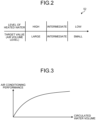
- FIG. 2 is an illustration illustrating an example of an air volume target value table that is stored in the storage unit 52.
- the air volume target value table is a table that is used when the radiation terminal 4A and the forced convection terminal 4B are operated at a time.
- the storage unit 52 stores an air volume level that is a target value of the air volume of the forced convection terminal 4B corresponding to the temperature level of the heated water.
- the temperature level of the heated water is a level corresponding to the temperature of the heated water that flows into the use-side heat exchanger of the forced convection terminal 4B, that is, the level corresponding to the current temperature that is a detected value of the temperature sensor 44.
- the temperature level of the heated water includes levels at three stages of "high” of a region where the current temperature is high, “low” of a region where the current temperature is low, and “intermediate” of a region where the current temperature is between “high” and “low” described above.
- the air volume level is a level of the air volume of the forced convection terminal 4B for the user to feel comfortable.
- the air volume level also includes levels at three stages of "large” at which the air volume is large, “small” at which the air volume is small, and “intermediate” at which the air volume is between “large” and “small”.
- the air volume level of the forced convection terminal 4B is large when the temperature level of the heated water is high, the air volume level of the forced convection terminal 4B is intermediate when the temperature level of the heated water is intermediate, and the air volume level of the forced convection terminal 4B is small when the temperature level of the heated water is low.
- the temperature level of the heated water is high, a decrease in the air volume for enabling a blow temperature that the user does not feel uncomfortable may be small.
- the temperature level of the heated water is low, the decrease in the air volume has to be increased to enable a blow temperature that the user does not feel uncomfortable.
- the air volume levels corresponding to the temperature levels of the heated water at three stages are set and this however does not apply to the case where an air volume corresponding to the temperature of the heated water is assigned and the air volume decreases as the temperature of the heated water decreases.
- the controller 53 controls the forced convection terminal 4B to reduce the air volume of the forced convection terminal 4B compared to the air volume in the case where only the forced convection terminal 4B is in operation. Specifically, when the radiation terminal 4A and the forced convection terminal 4B are operated at a time, the controller 53 reads the air volume level corresponding to a temperature level of the temperature of the heated water that is detected by the detector 51 from the storage unit 52 and controls the forced convection terminal 4B to enable the read air volume level.
- the controller 53 controls the heat source equipment 2 to increase the flow of the heated water to the forced convection terminal 4B and the radiation terminal 4A.
- the heat discharge from the heated water to the air is small compared to the rate of heat leak because of the wall, windows, the entrance of the room, etc.
- the temperature of the indoor space lowers. For this reason, even when a blow temperature that the user does not feel uncomfortable is enabled, there is a risk that the temperature of the indoor space would lower and the user would thus feel uncomfortable.
- the heat source equipment 2 controls the heat source equipment 2 to increase the flow of the heated water to the forced convection terminal 4B and the radiation terminal 4A, the heat discharge from the heated water to the air is increased to increase the blow temperature.
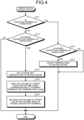
- FIG. 3 is an illustration illustrating an example of a relationship between air conditioning performance and the volume of circulated water.
- the air conditioning performance of the forced convection terminal 4B the air conditioning performance increases because the circulated flow of the heated water of the heat source equipment 2 increases as illustrated in FIG. 3 .
- FIG. 4 is a flowchart illustrating an example of processing operations of the control device 5 that relates to a temperature adjustment process.
- the control device 5 determines whether the radiation terminal 4A is in operation (step S11). When the radiation terminal 4A is in operation (step S11: Yes), the control device 5 determines whether the forced convection terminal 4B is in operation (step S12).
- step S12 When the forced convection terminal 4B is in operation (step S12: Yes), the control device 5 does not change the set temperature of the heated water (step S13) and reads an air volume level that is an air volume of a target value corresponding to a temperature level of the heated water that is the current temperature and that is detected by the detector from the storage unit 52 (step S14).
- the control device 5 sets the read air volume of the target value (air volume level) in the forced convection terminal 4B (step S15) and ends the processing operations illustrated in FIG. 4 .
- the control device 5 reads an air volume level corresponding to a temperature level of the detected temperature of the heated water from the storage unit 52 and controls the forced convection terminal 4B to enable the read air volume level.
- step S11: No the control device 5 determines whether the forced convection terminal 4B is in operation (step S16).
- step S16 determines whether the forced convection terminal 4B is in operation (step S16).
- step S16: Yes the control device 5 adjusts the set temperature of the heated water (step S17) and ends the processing operations illustrated in FIG. 4 .
- the control device 5 controls the heat source equipment 2 to adjust the current temperature of the heated water without changing the normal air volume level.
- the rotation rate of the compressor is increased to increase heat exchange between the refrigerant and the air and between the water and the refrigerant. As a result, it is possible to maintain the temperature that the user feels comfortable in the forced convection terminal 4B.
- step S16 When the forced convection terminal 4B is not in operation (step S16: No), the control device 5 ends the processing operations illustrated in FIG. 4 .
- step S12 When the forced convection terminal 4B is not in operation (step S12: No), the control device 5 ends the processing operations illustrated in FIG. 4 .
- the heat pump device 1 of the embodiment reads an air volume level corresponding to a temperature level of a temperature of heated water that is detected by the detector 51 from the storage unit 52 and controls the forced convection terminal 4B to enable the read air volume level.
- the heat pump device 1 of the embodiment reads an air volume level corresponding to a temperature level of a temperature of heated water that is detected by the detector 51 from the storage unit 52 and controls the forced convection terminal 4B to enable the read air volume level.
- the heat pump device 1 controls the heat source equipment 2 to increase the flow of the heated water to the forced convection terminal 4B and the radiation terminal 4A.
- the blow temperature by, instead of reducing the air volume of the forced convection terminal 4B that is the circulated volume of the air side, increasing the flow that is the volume of circulation of the heated water to the forced convection terminal 4B and the radiation terminal 4A and maintain air conditioning performance.
- the controller 53 reads an air volume level corresponding to a temperature level of heated water that is detected by the detector 51 from the storage unit 52 and controls the forced convection terminal 4B to enable the read air volume.
- the controller 53 may control the forced convection terminal 4B to reduce the air volume of the forced convection terminal 4B compared to the air volume in the case where only the forced convection terminal 4B is in operation and it is possible to make appropriate changes.
- the radiation terminal 4A it is possible to, while maintaining a temperature that a user feels comfortable in the radiation terminal 4A, it is possible to inhibit comfortableness to the user from lowering in the forced convection terminal 4B.
- reducing the air volume of the air passing through the use-side heat exchanger 41B in the forced convection terminal 4B increases the blow temperature.
- each component of each unit illustrated in the drawings need not necessarily be configured physically as illustrated in the drawings.
- specific modes of distribution and integration of each units are not limited to those illustrated in the drawings and all or part of the units can be configured by functional or physical distribution or integration in any unit according to various types of load and usage.
- each device may be executed on a CPU (Central Processing Unit) (or a microcomputer, such as a MPU (Micro Processing Unit) or a MCU (Micro Controller Unit)).
- a CPU Central Processing Unit
- MPU Micro Processing Unit
- MCU Micro Controller Unit
- all or any part of the various types of processing functions may be executed on a program that is analyzed and executed by the CPU (or a microcomputer, such as a MPU or a MCU) or on hardware according to a wired logic.
Landscapes
- Engineering & Computer Science (AREA)
- Physics & Mathematics (AREA)
- Chemical & Material Sciences (AREA)
- Combustion & Propulsion (AREA)
- Mechanical Engineering (AREA)
- General Engineering & Computer Science (AREA)
- Thermal Sciences (AREA)
- Fluid Mechanics (AREA)
- Heat-Pump Type And Storage Water Heaters (AREA)
- Air Conditioning Control Device (AREA)
- Other Air-Conditioning Systems (AREA)
- Steam Or Hot-Water Central Heating Systems (AREA)
Abstract
Description
- The present invention relates to a heat pump device.
- For example, a heat pump device that flows heated water that is produced by heat source equipment to an indoor terminal to warm an indoor space in which the indoor terminal is set is known. There are, as the indoor terminal, for example, a forced convection terminal that adjusts an indoor temperature by forced convection from the indoor terminal and a radiation terminal that adjusts the indoor temperature by radiant heat of the heated water that passes through the indoor terminal.
- When a heating operation is performed using a forced convection terminal that is connected to a heat pump device, heat is supplied to a user via indoor air and therefore, it is necessary to increase the temperature of the heated water to a high temperature compared to a case where a radiation terminal is used. For this reason, when a heating operation is performed using the forced convection terminal, setting a target temperature such that the temperature of the heated water is high in heating ensures comfortableness to the user.
- Patent Literature 1:
Japanese Laid-open Patent Publication No. 2019-70498 - In the conventional heat pump device, however, when the forced convection terminal and the radiation terminal are operated at a time, heated water at the same temperature as heated water that is supplied to the forced convection terminal is supplied to the radiation terminal. As a result, in the radiation terminal, heated water at a temperature exceeding a temperature that he user feels comfortable is supplied and thus the case where the user feels uncomfortable is assumed
- In view of the above-described problem, an object of the present invention is to provide a heat pump device that makes it possible to inhibit comfortableness to a user from lowering.
- According to an aspect of an embodiment, the heat pump device includes a heat source equipment, a radiation terminal, a forced convection terminal and a control device. The heat source equipment produces heated water by a heat source. The radiation terminal is connected to the heat source equipment and adjusts a temperature of an indoor space by radiation heat that is obtained by flowing the heated water from the heat source equipment into a radiation panel. The forced convection terminal is connected to the heat source equipment, flows the heated water from the heat source equipment into a use-side heat exchanger, and blows air on which heat exchange with the heated water is performed by the use-side heat exchanger using a blast fan and thus adjusts the temperature of the indoor space. The control device controls the heat source equipment, the radiation terminal, and the forced convection terminal. The control device includes a controller that, when the radiation terminal and the forced convection terminal are operated at a time, controls the forced convection terminal to reduce an air volume of the forced convection terminal compared to an air volume in a case where only the forced convection terminal is in operation.
- It is possible to inhibit comfortableness to a user from lowering as an aspect.
-
-
FIG. 1 is an illustration illustrating an example of a heat pump device of an embodiment. -
FIG. 2 is an illustration illustrating an example of an air volume target value table that is stored in a storage unit. -
FIG. 3 is an illustration illustrating an example of a relationship between the air conditioning performance and the volume of circulated water. -
FIG. 4 is a flowchart illustrating an example of processing operations of a control device that relate to a temperature adjustment process. - An embodiment of a heat pump device, etc., disclosed in the preset application will be described in detail below according to the drawings. Note that the embodiment does not limit the disclosed technique. Each embodiment illustrated below may be modified as appropriate within a range where no inconsistency is caused.
-
FIG. 1 is an illustration illustrating an example of a heat pump device 1 of the present embodiment. The heat pump device 1 illustrated inFIG. 1 includes heat source equipment 2 that produces heated water, a use-side terminal group 3 including a plurality of use-side terminals 4, and a control device 5 that controls the entire heat pump device 1. - The heat source equipment 2 includes a heat source 20 that produces heated water. The heat source 20 includes a refrigerant line 21 ad a water line 22. The refrigerant line 21 is, for example, a line in which a refrigerant circulates inside with a compressor and that performs heat exchange between the refrigerant that circulates and external air. In the water line 22, for example, water circulates inside and the water line 22 causes heat exchange between the water circulating inside and the refrigerant circulating in the refrigerant line 21, thereby producing heated water. The water line 22, for example, flows the heated water into the use-side terminal group 3 using a circulation pump, thereby adjusting the temperature of the indoor space in which the use-
side terminal 4 of the use-side terminal group 3 is arranged. - The use-side terminal group 3 includes the use-
side terminals 4, abranch pipe 31 and a mergingpipe 32. There are, as the use-side terminals 4 that are set in the indoor space, for example, a radiation terminal 4A, a forcedconvection terminal 4B, etc. - The radiation terminal 4A is, for example, a floor heating terminal and includes a radiation panel 41A that is an use-
side heat exchanger 41, is connected to the water line 22 in the heat source equipment 2, and adjusts the temperature of the indoor space using the radiant heat obtained by flowing the heated water from the water line 22 into the radiation panel 41A. - The forced
convection terminal 4B includes a use-side heat exchanger 41B (41), ablower fan 42, afan controller 43, and atemperature sensor 44. The use-side heat exchanger 41B is connected to the water line 22 in the heat source equipment 2, the heated water flows from the water line 22 into the use-side heat exchanger 41B, and theblower fan 42 blows the air on which heat exchange with the heated water is performed by the use-side heat exchanger 41B into the indoor space, thereby adjusting the temperature of the indoor space. Theblower fan 42 is a fan that generates forced convection. Thefan controller 43 adjusts the air volume by controlling the rotation rate of theblower fan 42. Thetemperature sensor 44 is a sensor that is arranged at the inlet of the use-side heat exchanger 41B and that detects a temperature of the heated water that flows into the use-side heat exchanger 41B. - The control device 5 controls the heat source equipment 2 and the radiation terminal 4A and the forced
convection terminal 4B that are the use-side terminal 4. The control device 5 includes a detector 51, astorage unit 52, and a controller 53. The detector 51 detects a current temperature of the heated water that is produced by the heat source equipment 2. Specifically, the detector 51 detects, as the current temperature, the temperature of the heated water that flows from thetemperature sensor 44 in the forcedconvection terminal 4B into the use-side heat exchanger 41B. - When the forced
convection terminal 4B and the radiation terminal 4A are operated at a time, the temperature of the heated water flowing into the forcedconvection terminal 4B and the radiation terminal 4A is conventionally set higher than that in the case where only the radiation terminal 4A is used. This is because the forcedconvection terminal 4B supplies heat to the user via indoor air and thus the heated water has to be higher than that in the case where only the radiation terminal 4A is used. As a result, the heated water at the same temperature as that of the heated water that is supplied to the forcedconvection terminal 4B is supplied to the radiation terminal 4A and, if the airflow to the forcedconvection terminal 4B is not lowered, the temperature of the air that is blown (blow temperature) lowers substantially, which makes the user uncomfortable. Thus, the embodiment focuses on lowering the heat discharge from the heated water to the air by changing the air flow to inhibit the temperature of the heated water from lowering. It is possible to calculate a heat discharge from the heated water to the air per unit of time by an air specific heat×an air density× an air flow×a difference in temperature. The difference in temperature is (an average temperature of the heated water in the heat exchanger-an air inlet temperature). In other words, reducing the air volume that is the air flow reduces the heat discharge from the heated water to the air per unit of time, which reduces a decrease in the temperature of the heated water. Accordingly, even when the temperature of the heated water is the same, reducing the air volume enables an appropriate temperature of the blow temperature from the forcedconvection terminal 4B. -
FIG. 2 is an illustration illustrating an example of an air volume target value table that is stored in thestorage unit 52. The air volume target value table is a table that is used when the radiation terminal 4A and the forcedconvection terminal 4B are operated at a time. Thestorage unit 52 stores an air volume level that is a target value of the air volume of the forcedconvection terminal 4B corresponding to the temperature level of the heated water. The temperature level of the heated water is a level corresponding to the temperature of the heated water that flows into the use-side heat exchanger of the forcedconvection terminal 4B, that is, the level corresponding to the current temperature that is a detected value of thetemperature sensor 44. The temperature level of the heated water includes levels at three stages of "high" of a region where the current temperature is high, "low" of a region where the current temperature is low, and "intermediate" of a region where the current temperature is between "high" and "low" described above. The air volume level is a level of the air volume of the forcedconvection terminal 4B for the user to feel comfortable. The air volume level also includes levels at three stages of "large" at which the air volume is large, "small" at which the air volume is small, and "intermediate" at which the air volume is between "large" and "small". - The air volume level of the forced
convection terminal 4B is large when the temperature level of the heated water is high, the air volume level of the forcedconvection terminal 4B is intermediate when the temperature level of the heated water is intermediate, and the air volume level of the forcedconvection terminal 4B is small when the temperature level of the heated water is low. When the temperature level of the heated water is high, a decrease in the air volume for enabling a blow temperature that the user does not feel uncomfortable may be small. On the other hand, when the temperature level of the heated water is low, the decrease in the air volume has to be increased to enable a blow temperature that the user does not feel uncomfortable. Note that, in the embodiment, the air volume levels corresponding to the temperature levels of the heated water at three stages are set and this however does not apply to the case where an air volume corresponding to the temperature of the heated water is assigned and the air volume decreases as the temperature of the heated water decreases. - When the radiation terminal 4A and the forced
convection terminal 4B are operated at a time, the controller 53 controls the forcedconvection terminal 4B to reduce the air volume of the forcedconvection terminal 4B compared to the air volume in the case where only the forcedconvection terminal 4B is in operation. Specifically, when the radiation terminal 4A and the forcedconvection terminal 4B are operated at a time, the controller 53 reads the air volume level corresponding to a temperature level of the temperature of the heated water that is detected by the detector 51 from thestorage unit 52 and controls the forcedconvection terminal 4B to enable the read air volume level. - After controlling the forced
convection terminal 4B to lower the air volume of the forcedconvection terminal 4B, when the temperature of the indoor space of the forcedconvection terminal 4B lowers, the controller 53 controls the heat source equipment 2 to increase the flow of the heated water to the forcedconvection terminal 4B and the radiation terminal 4A. When the heat discharge from the heated water to the air is small compared to the rate of heat leak because of the wall, windows, the entrance of the room, etc., the temperature of the indoor space lowers. For this reason, even when a blow temperature that the user does not feel uncomfortable is enabled, there is a risk that the temperature of the indoor space would lower and the user would thus feel uncomfortable. For this reason, by controlling the heat source equipment 2 to increase the flow of the heated water to the forcedconvection terminal 4B and the radiation terminal 4A, the heat discharge from the heated water to the air is increased to increase the blow temperature. -
FIG. 3 is an illustration illustrating an example of a relationship between air conditioning performance and the volume of circulated water. As for the air conditioning performance of the forcedconvection terminal 4B, the air conditioning performance increases because the circulated flow of the heated water of the heat source equipment 2 increases as illustrated inFIG. 3 . -
FIG. 4 is a flowchart illustrating an example of processing operations of the control device 5 that relates to a temperature adjustment process. InFIG. 4 , the control device 5 determines whether the radiation terminal 4A is in operation (step S11). When the radiation terminal 4A is in operation (step S11: Yes), the control device 5 determines whether the forcedconvection terminal 4B is in operation (step S12). - When the forced
convection terminal 4B is in operation (step S12: Yes), the control device 5 does not change the set temperature of the heated water (step S13) and reads an air volume level that is an air volume of a target value corresponding to a temperature level of the heated water that is the current temperature and that is detected by the detector from the storage unit 52 (step S14). - The control device 5 sets the read air volume of the target value (air volume level) in the forced
convection terminal 4B (step S15) and ends the processing operations illustrated inFIG. 4 . In other words, when the radiation terminal 4A and the forcedconvection terminal 4B are operated at a time, the control device 5 reads an air volume level corresponding to a temperature level of the detected temperature of the heated water from thestorage unit 52 and controls the forcedconvection terminal 4B to enable the read air volume level. As a result, while maintaining the temperature that the user feels comfortable in the radiation terminal 4A, it is possible to inhibit comfortableness to the user from lowering also in the forcedconvection terminal 4B. - When the radiation terminal 4A is not in operation at step S11 (step S11: No), the control device 5 determines whether the forced
convection terminal 4B is in operation (step S16). When the forcedconvection terminal 4B is in operation is in operation (step S16: Yes), the control device 5 adjusts the set temperature of the heated water (step S17) and ends the processing operations illustrated inFIG. 4 . In other words, when only the forcedconvection terminal 4B is operated, the control device 5 controls the heat source equipment 2 to adjust the current temperature of the heated water without changing the normal air volume level. Specifically, in the refrigerant line 21, the rotation rate of the compressor is increased to increase heat exchange between the refrigerant and the air and between the water and the refrigerant. As a result, it is possible to maintain the temperature that the user feels comfortable in the forcedconvection terminal 4B. - When the forced
convection terminal 4B is not in operation (step S16: No), the control device 5 ends the processing operations illustrated inFIG. 4 . When the forcedconvection terminal 4B is not in operation (step S12: No), the control device 5 ends the processing operations illustrated inFIG. 4 . - When the radiation terminal 4A and the forced
convection terminal 4B are operated at a time, the heat pump device 1 of the embodiment reads an air volume level corresponding to a temperature level of a temperature of heated water that is detected by the detector 51 from thestorage unit 52 and controls the forcedconvection terminal 4B to enable the read air volume level. As a result, while maintaining a temperature that the user feels comfortable in the radiation terminal 4A, it is possible to inhibit comfortableness to the user from lowering also in the forcedconvection terminal 4B. In other words, because the blow temperature is increase by lowering the air volume level of the forcedconvection terminal 4B even in a state where the temperature of the heated water is low, it is possible to avoid a situation in which comfortableness lowers even when the wind is on the user. - After controlling the forced
convection terminal 4B to lower the air volume of the forcedconvection terminal 4B, when the temperature of the indoor space of the forcedconvection terminal 4B lowers, the heat pump device 1 controls the heat source equipment 2 to increase the flow of the heated water to the forcedconvection terminal 4B and the radiation terminal 4A. As a result, it is possible to increase the blow temperature by, instead of reducing the air volume of the forcedconvection terminal 4B that is the circulated volume of the air side, increasing the flow that is the volume of circulation of the heated water to the forcedconvection terminal 4B and the radiation terminal 4A and maintain air conditioning performance. - Note that, for convenience of explanation, the case where, when the forced
convection terminal 4B and the radiation terminal 4A are operated at a time, the controller 53 reads an air volume level corresponding to a temperature level of heated water that is detected by the detector 51 from thestorage unit 52 and controls the forcedconvection terminal 4B to enable the read air volume. The controller 53 however may control the forcedconvection terminal 4B to reduce the air volume of the forcedconvection terminal 4B compared to the air volume in the case where only the forcedconvection terminal 4B is in operation and it is possible to make appropriate changes. As a result, in the radiation terminal 4A, it is possible to, while maintaining a temperature that a user feels comfortable in the radiation terminal 4A, it is possible to inhibit comfortableness to the user from lowering in the forcedconvection terminal 4B. For example, reducing the air volume of the air passing through the use-side heat exchanger 41B in the forcedconvection terminal 4B increases the blow temperature. In other words, without adjusting the temperature of heated water as in the conventional technique, it is possible to adjust the temperature of blow from the forcedconvection terminal 4B and thus ensure comfortableness. - Each component of each unit illustrated in the drawings need not necessarily be configured physically as illustrated in the drawings. In other words, specific modes of distribution and integration of each units are not limited to those illustrated in the drawings and all or part of the units can be configured by functional or physical distribution or integration in any unit according to various types of load and usage.
- Furthermore, all or given part of various types of processing functions implemented by each device may be executed on a CPU (Central Processing Unit) (or a microcomputer, such as a MPU (Micro Processing Unit) or a MCU (Micro Controller Unit)). Needless to say, all or any part of the various types of processing functions may be executed on a program that is analyzed and executed by the CPU (or a microcomputer, such as a MPU or a MCU) or on hardware according to a wired logic.
-
- 1
- HEAT PUMP DEVICE
- 2
- HEAT SOURCE EQUIPMENT
- 4A
- FORCED CONVECTION TERMINAL
- 5
- CONTROL DEVICE
- 20
- HEAT SOURCE
- 41A
- RADIATION PANEL
- 41B
- USE-SIDE HEAT EXCHANGER
- 51
- DETECTOR
- 52
- STORAGE UNIT
- 53
- CONTROLLER
Claims (4)
- A heat pump device comprising:a heat source equipment that produces heated water by a heat source;a radiation terminal that is connected to the heat source equipment and that adjusts a temperature of an indoor space by radiation heat that is obtained by flowing the heated water from the heat source equipment into a radiation panel;a forced convection terminal that is connected to the heat source equipment, flows the heated water from the heat source equipment into a use-side heat exchanger, and blows air on which heat exchange with the heated water is performed by the use-side heat exchanger using a blast fan and thus adjusts the temperature of the indoor space; anda control device that controls the heat source equipment, the radiation terminal, and the forced convection terminal,wherein the control device includes a controller that, when the radiation terminal and the forced convection terminal are operated at a time, controls the forced convection terminal to reduce an air volume of the forced convection terminal compared to an air volume in a case where only the forced convection terminal is in operation.
- The heat pump device according to claim 1, wherein the control device includesa detector that detects a temperature of the heated water that is produced by the heat source equipment; anda storage that stores a target value of the air volume of the forced convection terminal corresponding to the temperature of the heated water,wherein, when the radiation terminal and the forced convection terminal are in operation at a time, the controller reads the target value corresponding to the temperature of the heated water that is detected by the detector from the storage and controls the forced convection terminal to enable the read target value.
- The heat pump device according to claim 2, wherein the detector detects the temperature of the heated water that flows into the use-side heat exchanger as the heated water that is produced by the heat source equipment.
- The heat pump device according to claim 1 or 2, wherein, when the temperature of the indoor space of the forced convection terminal lowers after the controller controls the forced convection terminal to lower the air volume of the forced convection terminal, the controller controls the heat source equipment to increase a flow of the heated water to the forced convection terminal and the radiation terminal.
Applications Claiming Priority (2)
| Application Number | Priority Date | Filing Date | Title |
|---|---|---|---|
| JP2022061047A JP7484958B2 (en) | 2022-03-31 | 2022-03-31 | Heat pump equipment |
| PCT/JP2023/012634 WO2023190574A1 (en) | 2022-03-31 | 2023-03-28 | Heat pump device |
Publications (2)
| Publication Number | Publication Date |
|---|---|
| EP4502478A1 true EP4502478A1 (en) | 2025-02-05 |
| EP4502478A4 EP4502478A4 (en) | 2026-04-01 |
Family
ID=88201873
Family Applications (1)
| Application Number | Title | Priority Date | Filing Date |
|---|---|---|---|
| EP23780583.3A Pending EP4502478A4 (en) | 2022-03-31 | 2023-03-28 | HEAT PUMP DEVICE |
Country Status (5)
| Country | Link |
|---|---|
| EP (1) | EP4502478A4 (en) |
| JP (1) | JP7484958B2 (en) |
| CN (1) | CN119013518A (en) |
| AU (1) | AU2023246174B2 (en) |
| WO (1) | WO2023190574A1 (en) |
Family Cites Families (7)
| Publication number | Priority date | Publication date | Assignee | Title |
|---|---|---|---|---|
| JPS57137943U (en) * | 1981-02-20 | 1982-08-28 | ||
| JPH09287748A (en) * | 1996-04-18 | 1997-11-04 | Fujitsu General Ltd | Hot water heating system |
| JP2003322348A (en) | 2002-04-26 | 2003-11-14 | Osaka Gas Co Ltd | Warm water type floor heater |
| WO2011083516A1 (en) * | 2010-01-08 | 2011-07-14 | ダイキン工業株式会社 | Radiator |
| DE102012022158B4 (en) * | 2012-11-10 | 2021-10-07 | Robert Bosch Gmbh | Indoor air conditioning with a fan coil unit |
| JP5981396B2 (en) * | 2013-07-10 | 2016-08-31 | サンポット株式会社 | Heat pump heat source machine |
| JP6912349B2 (en) * | 2017-10-11 | 2021-08-04 | 株式会社コロナ | Temperature control system |
-
2022
- 2022-03-31 JP JP2022061047A patent/JP7484958B2/en active Active
-
2023
- 2023-03-28 EP EP23780583.3A patent/EP4502478A4/en active Pending
- 2023-03-28 AU AU2023246174A patent/AU2023246174B2/en active Active
- 2023-03-28 CN CN202380026899.1A patent/CN119013518A/en active Pending
- 2023-03-28 WO PCT/JP2023/012634 patent/WO2023190574A1/en not_active Ceased
Also Published As
| Publication number | Publication date |
|---|---|
| JP2023151441A (en) | 2023-10-16 |
| JP7484958B2 (en) | 2024-05-16 |
| WO2023190574A1 (en) | 2023-10-05 |
| EP4502478A4 (en) | 2026-04-01 |
| AU2023246174B2 (en) | 2025-11-20 |
| CN119013518A (en) | 2024-11-22 |
| AU2023246174A1 (en) | 2024-09-26 |
Similar Documents
| Publication | Publication Date | Title |
|---|---|---|
| US11879658B2 (en) | Air-conditioning ventilation system | |
| US11137152B2 (en) | Method and apparatus for reduction of condensate re-evaporation during cooling part-load duty cycling | |
| KR101330986B1 (en) | Apparatus and method for controlling air condition | |
| KR20170109309A (en) | Dehumidification control apparatus for air conditioner and method thereof | |
| EP3760939B1 (en) | Air conditioner | |
| EP2332757A1 (en) | Air conditioning device for vehicle, and method and program for controlling air conditioning device for vehicle | |
| AU2004230976B2 (en) | Air conditioning system | |
| CN111637526B (en) | Control method of mixed and collocated multi-split system | |
| AU2023246174B2 (en) | Heat pump device | |
| JP6292983B2 (en) | Air conditioning system | |
| JPH1151445A (en) | Radiant air conditioning system | |
| KR20020073861A (en) | Multi-Type Conditioning System | |
| JP2000104978A (en) | Air conditioner | |
| EP4130590A1 (en) | Ventilation/air conditioning system | |
| JP2000291993A (en) | Operation control device for ceiling cassette type air conditioner | |
| US20210063025A1 (en) | Method and system for protecting a single-stage furnace in a multi-zone system | |
| JP7437552B2 (en) | Ventilation systems and methods | |
| US12595929B2 (en) | Air-conditioning system | |
| JP7310964B1 (en) | heat pump equipment | |
| JP2912846B2 (en) | Air conditioner | |
| EP4414622A1 (en) | Air conditioner | |
| JP2020134074A (en) | Air conditioning system, control device for air conditioning system | |
| CN116066972A (en) | Air-conditioning air outlet control method, device, air conditioner and storage medium | |
| JP2026019431A (en) | Air conditioning control device and program | |
| JP3144855B2 (en) | Air conditioner |
Legal Events
| Date | Code | Title | Description |
|---|---|---|---|
| STAA | Information on the status of an ep patent application or granted ep patent |
Free format text: STATUS: THE INTERNATIONAL PUBLICATION HAS BEEN MADE |
|
| PUAI | Public reference made under article 153(3) epc to a published international application that has entered the european phase |
Free format text: ORIGINAL CODE: 0009012 |
|
| STAA | Information on the status of an ep patent application or granted ep patent |
Free format text: STATUS: REQUEST FOR EXAMINATION WAS MADE |
|
| 17P | Request for examination filed |
Effective date: 20240918 |
|
| AK | Designated contracting states |
Kind code of ref document: A1 Designated state(s): AL AT BE BG CH CY CZ DE DK EE ES FI FR GB GR HR HU IE IS IT LI LT LU LV MC ME MK MT NL NO PL PT RO RS SE SI SK SM TR |
|
| DAV | Request for validation of the european patent (deleted) | ||
| DAX | Request for extension of the european patent (deleted) | ||
| A4 | Supplementary search report drawn up and despatched |
Effective date: 20260303 |
|
| RIC1 | Information provided on ipc code assigned before grant |
Ipc: F24F 5/00 20060101AFI20260225BHEP Ipc: F24D 3/00 20220101ALI20260225BHEP Ipc: F24F 11/64 20180101ALI20260225BHEP Ipc: F24F 11/74 20180101ALI20260225BHEP Ipc: F24F 11/83 20180101ALI20260225BHEP Ipc: F24F 140/20 20180101ALI20260225BHEP |