EP4502477A1 - An outdoor unit of air conditioner - Google Patents
An outdoor unit of air conditioner Download PDFInfo
- Publication number
- EP4502477A1 EP4502477A1 EP24151440.5A EP24151440A EP4502477A1 EP 4502477 A1 EP4502477 A1 EP 4502477A1 EP 24151440 A EP24151440 A EP 24151440A EP 4502477 A1 EP4502477 A1 EP 4502477A1
- Authority
- EP
- European Patent Office
- Prior art keywords
- grille
- plate
- cover
- coupled
- outdoor unit
- Prior art date
- Legal status (The legal status is an assumption and is not a legal conclusion. Google has not performed a legal analysis and makes no representation as to the accuracy of the status listed.)
- Pending
Links
Images





Classifications
-
- F—MECHANICAL ENGINEERING; LIGHTING; HEATING; WEAPONS; BLASTING
- F24—HEATING; RANGES; VENTILATING
- F24F—AIR-CONDITIONING; AIR-HUMIDIFICATION; VENTILATION; USE OF AIR CURRENTS FOR SCREENING
- F24F1/00—Room units for air-conditioning, e.g. separate or self-contained units or units receiving primary air from a central station
- F24F1/06—Separate outdoor units, e.g. outdoor unit to be linked to a separate room comprising a compressor and a heat exchanger
- F24F1/46—Component arrangements in separate outdoor units
- F24F1/48—Component arrangements in separate outdoor units characterised by air airflow, e.g. inlet or outlet airflow
- F24F1/54—Inlet and outlet arranged on opposite sides
-
- F—MECHANICAL ENGINEERING; LIGHTING; HEATING; WEAPONS; BLASTING
- F24—HEATING; RANGES; VENTILATING
- F24F—AIR-CONDITIONING; AIR-HUMIDIFICATION; VENTILATION; USE OF AIR CURRENTS FOR SCREENING
- F24F13/00—Details common to, or for air-conditioning, air-humidification, ventilation or use of air currents for screening
- F24F13/08—Air-flow control members, e.g. louvres, grilles, flaps or guide plates
- F24F13/082—Grilles, registers or guards
- F24F13/084—Grilles, registers or guards with mounting arrangements, e.g. snap fasteners for mounting to the wall or duct
-
- F—MECHANICAL ENGINEERING; LIGHTING; HEATING; WEAPONS; BLASTING
- F24—HEATING; RANGES; VENTILATING
- F24F—AIR-CONDITIONING; AIR-HUMIDIFICATION; VENTILATION; USE OF AIR CURRENTS FOR SCREENING
- F24F1/00—Room units for air-conditioning, e.g. separate or self-contained units or units receiving primary air from a central station
- F24F1/06—Separate outdoor units, e.g. outdoor unit to be linked to a separate room comprising a compressor and a heat exchanger
- F24F1/56—Casing or covers of separate outdoor units, e.g. fan guards
-
- F—MECHANICAL ENGINEERING; LIGHTING; HEATING; WEAPONS; BLASTING
- F04—POSITIVE - DISPLACEMENT MACHINES FOR LIQUIDS; PUMPS FOR LIQUIDS OR ELASTIC FLUIDS
- F04D—NON-POSITIVE-DISPLACEMENT PUMPS
- F04D29/00—Details, component parts, or accessories
- F04D29/70—Suction grids; Strainers; Dust separation; Cleaning
- F04D29/701—Suction grids; Strainers; Dust separation; Cleaning especially adapted for elastic fluid pumps
- F04D29/703—Suction grids; Strainers; Dust separation; Cleaning especially adapted for elastic fluid pumps specially for fans, e.g. fan guards
-
- F—MECHANICAL ENGINEERING; LIGHTING; HEATING; WEAPONS; BLASTING
- F24—HEATING; RANGES; VENTILATING
- F24F—AIR-CONDITIONING; AIR-HUMIDIFICATION; VENTILATION; USE OF AIR CURRENTS FOR SCREENING
- F24F1/00—Room units for air-conditioning, e.g. separate or self-contained units or units receiving primary air from a central station
- F24F1/06—Separate outdoor units, e.g. outdoor unit to be linked to a separate room comprising a compressor and a heat exchanger
- F24F1/38—Fan details of outdoor units, e.g. bell-mouth shaped inlets or fan mountings
-
- F—MECHANICAL ENGINEERING; LIGHTING; HEATING; WEAPONS; BLASTING
- F24—HEATING; RANGES; VENTILATING
- F24F—AIR-CONDITIONING; AIR-HUMIDIFICATION; VENTILATION; USE OF AIR CURRENTS FOR SCREENING
- F24F1/00—Room units for air-conditioning, e.g. separate or self-contained units or units receiving primary air from a central station
- F24F1/06—Separate outdoor units, e.g. outdoor unit to be linked to a separate room comprising a compressor and a heat exchanger
- F24F1/56—Casing or covers of separate outdoor units, e.g. fan guards
- F24F1/58—Separate protective covers for outdoor units, e.g. solar guards, snow shields or camouflage
-
- F—MECHANICAL ENGINEERING; LIGHTING; HEATING; WEAPONS; BLASTING
- F24—HEATING; RANGES; VENTILATING
- F24F—AIR-CONDITIONING; AIR-HUMIDIFICATION; VENTILATION; USE OF AIR CURRENTS FOR SCREENING
- F24F13/00—Details common to, or for air-conditioning, air-humidification, ventilation or use of air currents for screening
- F24F13/08—Air-flow control members, e.g. louvres, grilles, flaps or guide plates
- F24F13/082—Grilles, registers or guards
-
- F—MECHANICAL ENGINEERING; LIGHTING; HEATING; WEAPONS; BLASTING
- F24—HEATING; RANGES; VENTILATING
- F24F—AIR-CONDITIONING; AIR-HUMIDIFICATION; VENTILATION; USE OF AIR CURRENTS FOR SCREENING
- F24F2221/00—Details or features not otherwise provided for
- F24F2221/26—Details or features not otherwise provided for improving the aesthetic appearance
-
- F—MECHANICAL ENGINEERING; LIGHTING; HEATING; WEAPONS; BLASTING
- F24—HEATING; RANGES; VENTILATING
- F24F—AIR-CONDITIONING; AIR-HUMIDIFICATION; VENTILATION; USE OF AIR CURRENTS FOR SCREENING
- F24F2221/00—Details or features not otherwise provided for
- F24F2221/52—Weather protecting means, e.g. against wind, rain or snow
Definitions
- the present disclosure relates to an outdoor unit of an air conditioner.
- An air conditioner is a device that cools and heats an indoor space by heat exchange between a refrigerant flowing in a heat exchange cycle and indoor air and outdoor air.
- the air conditioner includes a compressor that compresses the refrigerant, an outdoor heat exchanger that exchanges heat between the refrigerant and outdoor air, and an indoor heat exchanger that exchanges heat between the refrigerant and indoor air.
- the outdoor unit of the air conditioner may include a case, the compressor and the outdoor heat exchanger accommodated inside the case, and a fan for intake and exhaust of air.
- an outdoor unit cover may be provided on the outer surface of the outdoor unit to block sunlight from the outside or prevent rainwater or foreign substances from penetrating.
- the outdoor unit cover is installed to cover the upper surface or the side of the outdoor unit, and thus can block sunlight or prevent rainwater from penetrating.
- the conventional outdoor unit cover is used to simply cover the upper surface or the side surface of the outdoor unit, so it cannot protect the front surface of the outdoor unit and the overall outer appearance of the outdoor unit is poor.
- Patent Document 1 Korean Patent Publication No. 10-2022-0010865 (January 27, 2022 )
- An object of the present disclosure is to provide an outdoor unit of an air conditioner that can protect the front surface of the outdoor unit.
- Another object of the present disclosure is to provide an outdoor unit of an air conditioner that can have a beautiful outer appearance of the front appearance of the outdoor unit.
- Another object of the present disclosure is to provide an outdoor unit of an air conditioner that can prevent infiltration of rainwater or foreign substances from the outside.
- Another object of the present disclosure is to provide an outdoor unit of an air conditioner in which a grille assembly can be stably coupled to the front surface of the outdoor unit.
- Another object of the present disclosure is to provide an outdoor unit of an air conditioner in which the grille assembly can be easily installed and removed.
- Another object of the present disclosure is to provide an outdoor unit of an air conditioner in which air flow resistance to air discharged through a grille assembly can be minimized.
- the outdoor unit of the air conditioner according to an embodiment of the present disclosure includes a case that forms the outer appearance.
- the outdoor unit includes a barrier dividing an inner portion of the case into a heat exchange space and an electric space.
- the outdoor unit includes a heat exchanger disposed in the heat exchange space.
- the outdoor unit includes a fan disposed in the heat exchange space.
- the outdoor unit may further include a compressor disposed in the electric space.
- the outdoor unit includes a grille assembly detachably coupled to a front surface of the case.
- the grille assembly includes a first grille plate coupled to the front surface of the case corresponding to the front of the heat exchange space.
- the grille assembly includes a second grille plate coupled to the front surface of the case corresponding to the front of the electric space.
- the grille assembly includes a grille cover coupled to cover an upper portion of the first grille plate and an upper portion of the second grille plate.
- a plurality of hook holes may be formed on the front surface of the case.
- a first hook may be formed that is coupled to some hook holes among the plurality of hook holes
- a second hook may be formed that is coupled to other hook holes among the plurality of hook holes.
- the direction in which the first hook is coupled to some hook holes among the plurality of hook holes may be opposite to the direction in which the second hook is coupled to other hook holes among the plurality of hook holes.
- the case may include a base panel.
- the case may further include a first front panel erected on a front end portion of the base panel and forming a front surface of the heat exchange space.
- the case may further include a second front panel erected on a front end portion of the base panel and forming a front surface of the electric space.
- the first grille plate may be coupled to cover a front surface of the first front panel.
- the second grille plate may be coupled to cover a front surface of the second front panel.
- the fan may be disposed on the front of the heat exchanger.
- the first grille plate may be disposed on the front of the fan.
- the case may further include an orifice coupled to an inside of the first front panel
- the fan may be disposed on the rear of the orifice.
- the first grille plate may include a first plate coupled to the front surface of the case.
- the first grille plate may further include a first cover portion coupled to the upper end of the first plate.
- the first grille plate may further include a first grille portion provided on a front surface of the first plate.
- the first grille portion may be disposed on the front of the fan.
- the first grille portion may include a plurality of horizontal ribs spaced apart from each other in a vertical direction.
- the first grille portion may further include a plurality of longitudinal ribs that connect the plurality of horizontal ribs and are spaced apart from each other.
- the second grille plate may include a second plate coupled to the front surface of the case.
- the second grille plate may further include a second cover portion coupled to an upper end of the second plate.
- the second grille plate may further include a second grille portion provided on a front surface of the second plate.
- a front surface of the first grille portion and a front surface of the second grille portion may be disposed on the same plane.
- An upper surface of the first cover portion and an upper surface of the second cover portion may be disposed on the same plane.
- the grille cover may be coupled to cover the upper surface of the first cover portion and the upper surface of the second cover portion.
- the grille cover may include a front surface portion forming a front surface thereof.
- the grille cover may further include an upper surface portion forming an upper surface thereof.
- the grille cover may further include side portions forming both sides thereof.
- each of the first grille plate and the second grille plate may be inserted and accommodated inside the grille cover.
- the rear and bottom surfaces of the grille cover may be open.
- a first coupling groove may be formed on the upper surface of each of the first grille plate and the second grille plate.
- a coupling rib may be formed on the grille cover, which extends rearward from the front surface portion and is coupled to the first coupling groove.
- the coupling rib may include a first rib extending rearward from a rear surface of the front surface portion.
- the coupling rib may further include a second rib extending downward from an end portion of the first rib.
- the second rib may be engaged with an inside of the first coupling groove.
- a second coupling groove may be formed on each side of the first grille plate and the second grille plate.
- a coupling protrusion may be formed on the grille cover, which extends inward from the side portion and is coupled to the second coupling groove.
- the coupling protrusion may include a first protrusion extending from an inner surface of the side portion toward an inner center.
- the coupling protrusion may further include a second protrusion extending from the inner surface of the side portion toward the inner center and spaced upward from the first protrusion.
- An insertion groove may be formed at a front end portion of each of the first grille plate and the second grille plate.
- An insertion portion may be formed in the grille cover, which extends rearward from a lower end of the front surface portion and is coupled to the insertion groove.
- FIG. 1 is a front perspective view illustrating an outdoor unit of an air conditioner according to an embodiment of the present disclosure
- FIG. 2 is a front perspective view illustrating the outdoor unit in a state where the grille assembly is coupled according to an embodiment of the present disclosure.
- the outdoor unit 10 of an air conditioner includes a case that forms an outer appearance of the outdoor unit.
- the case may include a base panel 11 forming the bottom surface of the outdoor unit 10, a first front panel 12 erected on one side of the front end portion of the base panel 11, and a second front panel 13 erected on the other side of the front end portion of the base panel 11.
- the case may further include a side panel 14 erected on the side of the base panel 11 and a top panel 15 forming the upper surface of the outdoor unit 10.
- the outdoor unit 10 may further include an orifice 16 coupled to the first front panel 12, a fan 17 disposed behind the orifice 16, and a heat exchanger erected on the upper surface of the base panel 11.
- the fan 17 may be disposed on the front of the heat exchanger.
- the outdoor unit 10 may further include a barrier erected on the upper surface of the base panel 11.
- the barrier can divide the upper space of the base panel 11 into a heat exchange space on the left and an electric space on the right.
- the heat exchanger may be disposed in the heat exchange space.
- the heat exchanger may be bent and extended along the side and rear end portions of the base panel 11 to define the side and the rear surface of the heat exchange space.
- One side end portion of the first front panel 12 may be coupled to the front end portion of the heat exchanger, and the other side end portion may be coupled to the front end portion of the barrier.
- the rear end portion of the barrier may be connected to the side end portion of the heat exchanger.
- the outdoor unit 10 may further include a compressor and a heat storage tank erected on the upper surface of the base panel 11 corresponding to the electric space.
- the refrigerant that has passed through the heat storage tank may be guided to the heat exchanger along the refrigerant pipe.
- the refrigerant that has passed through the heat exchanger may pass through an expansion valve and then be guided to the heat exchanger of the indoor unit.
- the refrigerant that has passed through the indoor unit may pass through a gas-liquid separator and then be recovered by the compressor.
- the air that has passed through the heat exchanger flows from the rear surface to the front surface of the fan 17, passes through the orifice 16, and then can be discharged to the outside of the outdoor unit 10.
- a portion of the plurality of blades constituting the fan 17 can be accommodated inside the orifice 16 so that all air forced to flow by the fan 17 passes through the orifice 16.
- the outdoor unit 10 may further include a grille assembly 100 detachably coupled to the front surface of the outdoor unit 10.
- the grille assembly 100 is installed on the front surface of the outdoor unit 10 to protect the front surface of the outdoor unit 10.
- the grille assembly 100 can block rainwater or foreign substances introduced into the front surface of the outdoor unit 10 from the outside.
- the grille assembly 100 can cover the entire front surface of the outdoor unit 10 to improve the outer appearance of the front surface of the outdoor unit 10.
- the grille assembly 100 may include a first grille plate 110, a second grille plate 120, and a grille cover 130 coupled to the front surface of the outdoor unit 10.
- the first grille plate 110 may be coupled to the front surface of the outdoor unit 10 and cover a portion of the front surface of the outdoor unit 10.
- the first grille plate 110 may be detachably coupled to the front surface of the first front panel 12.
- the first grille plate 110 may cover a portion of the orifice 16 where the fan 17 is accommodated.
- the second grille plate 120 may be coupled to the front surface of the outdoor unit 10 and cover another portion of the front surface of the outdoor unit 10.
- the second grille plate 120 may be detachably coupled to the front surface of the second front panel 13.
- the second grille plate 120 may be disposed on a side of the first grille plate 110.
- the first grille plate 110 and the second grille plate 120 may be connected to each other.
- the first grille plate 110 and the second grille plate 120 may be disposed side by side in the left and right direction on the front surface of the outdoor unit 10.
- the front surface of the first grille plate 110 and the front surface of the second grille plate 120 may be disposed on the same plane.
- the grille cover 130 is coupled to the first grille plate 110 and the second grille plate 120, and has a function of fixing the first grille plate 110 and the second grille plate 120.
- the grille cover 130 may be coupled to the upper portion of the first grille plate 110 and the upper portion of the second grille plate 120.
- the grille cover 130 may be coupled to cover the upper portion of the first grille plate 110 and the upper portion of the second grille plate 120.
- the grille cover 130 may be disposed on the upper end of the front surface of the outdoor unit 10.
- a portion of the grille cover 130 may be disposed on the upper end of the first front panel 12, and another portion of the grille cover 130 may be disposed on the upper end of the second front panel 13.
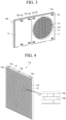
- FIG. 3 is a rear perspective view illustrating the front panel in a state where the grille assembly is coupled
- FIG. 4 is a front perspective view illustrating a first grille plate according to an embodiment of the present disclosure
- FIG. 5 is a rear view illustrating the first grille plate
- FIG. 6 is a top view illustrating the first grille plate.
- the first grille plate 110 may be coupled to the front surface of the first front panel 12 and cover the front surface of the first front panel 12.
- the first grille plate 110 may have a shape corresponding to the shape of the front surface of the first front panel 12.
- the first grille plate 110 may have a square panel shape.
- the first grille plate 110 may include a first plate 111 coupled to the front surface of the first front panel 12, a first cover portion 112 coupled to the upper end of the first plate 111, and a first grille portion 113 provided on the front surface of the first plate 111.
- the first plate 111 may define both sides and the rear surface of the first grille plate 110, the first cover portion 112 may define the upper surface of the first grille plate 110, and the first cover portion 112 may define the front surface of the first grille plate 113.
- the first plate 111 is formed in a shape corresponding to the front surface of the first front panel 12 and can be coupled to the front surface of the first front panel 12.
- the first plate 111 may be formed as a square panel with a constant thickness in the front and rear direction.
- the first plate 111 may include a first hook 111a to be coupled to the first front panel 12.
- the first hook 111a may be formed to extend rearward from the rear surface of the first plate 111.
- a plurality of first hooks 111a may be formed on the rear surface of the first plate 111.
- the plurality of first hooks 111a may be disposed to be spaced apart along the rear edge of the first plate 111.
- the first hook 111a may be inserted into and fastened to the first hook hole 12a formed in the first front panel 12.
- the first hook hole 12a may be formed to penetrate from the front surface to the rear surface of the first front panel 12.
- the first hook hole 12a may be formed at an edge of the first front panel 12.
- a plurality of first hook holes 12a may be formed to be spaced apart from each other along the edge of the first front panel 12.
- the through-hole 111b may be formed in the center of the first plate 111.
- the through-hole 11 1b may be formed by penetrating from the front surface to the rear surface of the first plate 111.
- the through-hole 111b may be formed in a shape corresponding to the orifice 16.
- the through-hole 111b is disposed to face the orifice 16, so that air passing through the orifice 16 can be discharged to the outside of the outdoor unit 10 through the first grille portion 113.
- the first cover portion 112 may be mounted on the upper surface of the first plate 111.
- the first cover portion 112 may be formed in a plate shape that is narrow in the front and rear direction and long in the left and right direction.
- the first cover portion 112 may be coupled to the upper end of the first plate 111.
- the upper surface of the first plate 111 may be covered by the first cover portion 112.
- the first cover portion 112 may include a first coupling groove 112a for being coupled to the grille cover 130.
- the first coupling groove 112a may be formed on the upper surface of the first cover portion 112.
- the first coupling groove 112a may be formed by cutting a portion of the upper surface of the first cover portion 112.
- a plurality of first coupling grooves 112a may be formed.
- the plurality of first coupling grooves 112a may be disposed to be spaced apart in the longitudinal direction on the upper surface of the first cover portion 112.
- the first cover portion 112 may further include a second coupling groove 112b for being coupled to the grille cover 130.
- the second coupling groove 112b may be formed on the side of the first cover portion 112.
- the second coupling groove 112b may be formed by recessing a portion of the side of the first cover portion 112.
- the second coupling groove 112b may be formed on one of both sides of the first cover portion 112.
- the second coupling groove 112b may be formed on the left side of both sides of the first cover portion 112.
- the first grille portion 113 may include a plurality of ribs to form a grille shape.
- the first grille portion 113 may be provided on the front surface of the first plate 111.
- the first grille portion 113 may protrude from the inside to the front surface of the first plate 111.
- the first grille portion 113 may include a plurality of horizontal ribs 113a extending in the horizontal direction and a plurality of longitudinal ribs 113b extending in the vertical direction.
- the plurality of horizontal ribs 113a may be formed entirely on the front surface of the first plate 111.
- the plurality of horizontal ribs 113a may be disposed to be spaced apart in the vertical direction on the front surface of the first plate 111.
- the plurality of horizontal ribs 113a may be spaced apart from each other at equal intervals.
- the plurality of longitudinal ribs 113b may be formed on a portion of the front surface of the first plate 111.
- the plurality of longitudinal ribs 113b may be provided in a corresponding area of the first plate 111 facing the through-hole 111b.
- the plurality of longitudinal ribs 113b may be disposed to cover the through-hole 111b.
- the plurality of longitudinal ribs 113b may be formed only in the area of the circular flow path portion forming the air flow path.
- the plurality of longitudinal ribs 113b may be disposed to connect two adjacent horizontal ribs 113a.
- the plurality of longitudinal ribs 113b may be disposed at irregular intervals between the plurality of horizontal ribs 113a.
- the horizontal ribs 113a and the longitudinal ribs 113b Due to the configuration of the horizontal ribs 113a and the longitudinal ribs 113b, exposure of the fan 17 to the outside of the outdoor unit 10 can be minimized. In addition, since the horizontal ribs 113a and longitudinal ribs 113b cover the orifice 16 where the fan 17 is accommodated, it is possible to prevent rainwater or foreign substances from penetrating from the outside.
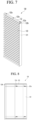
- FIG. 7 is a front perspective view illustrating a second grille plate according to an embodiment of the present disclosure
- FIG. 8 is a rear view illustrating the second grille plate
- FIG. 9 is a top view illustrating the second grille plate.
- the second grille plate 120 may be coupled to the front surface of the second front panel 13 and cover the front surface of the second front panel 13.
- the second grille plate 120 may have a shape corresponding to the shape of the front surface of the second front panel 13.
- the second grille plate 120 may have a square panel shape.
- the second grille plate 120 may be formed smaller than the first grille plate 110. However, it is not limited to this, and when the second front panel 13 is formed larger than the first front panel 12, the second grille plate 120 may be formed larger than the first grille plate 110.
- the second grille plate 120 may include a second plate 121 coupled to the front surface of the second front panel 13, a second cover portion 122 coupled to the upper end of the second plate 121, and a second grille portion 123 provided on the front surface of the second plate 121.
- the second plate 121 defines both sides and the rear surface of the second grille plate 120
- the second cover portion 122 defines the upper surface of the second grille plate 120
- the second grille portion 123 may define the front surface of the second grille plate 123.
- the second plate 121 is formed in a shape corresponding to the front surface of the second front panel 13 and can be coupled to the front surface of the second front panel 13.
- the second plate 121 may be formed as a square panel with a constant thickness in the front and rear direction.
- the thickness of the second plate 121 may be formed to be the same as the thickness of the first plate 111.
- the second plate 121 may include a second hook 121a to be coupled to the second front panel 13.
- the second hook 121a may be formed to extend rearward from the rear surface of the second plate 121.
- a plurality of second hooks 121a may be formed on the rear surface of the second plate 121.
- the plurality of second hooks 121a may be disposed to be spaced apart along the rear edge of the second plate 121.
- the second hook 121a may be inserted into and fastened to the second hook hole 13a formed in the second front panel 13.
- the second hook hole 12a may be formed to penetrate from the front surface to the rear surface of the second front panel 13.
- the second hook hole 13a may be formed at the edge of the second front panel 13.
- a plurality of second hook holes 13a may be formed to be spaced apart along the edge of the second front panel 13.
- the second cover portion 122 may be mounted on the upper surface of the second plate 121.
- the second cover portion 122 may be formed to correspond to the shape of the first cover portion 112.
- the second cover portion 122 may be formed in a plate shape that is narrow in the front and rear direction and long in the left and right direction.
- the second cover portion 122 may be coupled to the upper end of the second plate 121.
- the upper surface of the second plate 121 may be covered by the second cover portion 122.
- the second cover portion 122 may include a first coupling groove 122a for being coupled to the grille cover 130.
- the first coupling groove 122a of the second cover portion 122 may be formed to correspond to the shape of the first coupling groove 112a of the first cover portion 112.
- the first coupling groove 122a may be formed on the upper surface of the second cover portion 122.
- the first coupling groove 122a may be formed by cutting a portion of the upper surface of the second cover portion 122.
- a plurality of first coupling grooves 122a may be formed.
- the plurality of first coupling grooves 122a may be disposed to be spaced apart in the longitudinal direction on the upper surface of the second cover portion 122.
- the second cover portion 122 may further include a second coupling groove 122b for being coupled to the grille cover 130.
- the second coupling groove 122b of the second cover portion 122 may be formed to correspond to the shape of the second coupling groove 112b of the first cover portion 112.
- the second coupling groove 122b may be formed on the side of the second cover portion 122.
- the second coupling groove 122b may be formed by recessing a portion of the side of the second cover portion 122.
- the second coupling groove 122b may be formed on one of both sides of the second cover portion 122.
- the second coupling groove 122b may be formed on the right side of both sides of the second cover portion 122.
- the second grille portion 123 may include a plurality of ribs to form a grille shape.
- the second grille portion 123 may be provided on the front surface of the second plate 121.
- the second grille portion 123 may protrude from the inside to the front surface of the second plate 121.
- the second grille portion 123 may include a plurality of horizontal ribs extending in the horizontal direction.
- the plurality of horizontal ribs may be formed entirely on the front surface of the second plate 121.
- the plurality of horizontal ribs may be disposed to be spaced apart in the vertical direction on the front surface of the second plate 121.
- the plurality of horizontal ribs may be spaced apart from each other at equal intervals.
- the upper surface of the first cover portion 112 and the upper surface of the second cover portion 122 may be disposed on the same plane.
- the grille cover 130 may be coupled to cover the upper surface of the first cover portion 112 and the upper surface of the second cover portion 122.
- the front surface of the first grille portion 113 and the front surface of the second grille portion 123 may be disposed on the same plane.
- FIG. 10 is a front perspective view illustrating a grille cover according to an embodiment of the present disclosure
- FIG. 11 is a rear view of the grille cover illustrating a portion of the rear of the grille cover
- FIG. 12 is a bottom view illustrating the grille cover.
- the grille cover 130 may be coupled and fixed to the upper portions of the first grille plate 110 and the second grille plate 120, respectively.
- the grille cover 130 may be narrow in the front and rear direction and long in the left and right direction.
- the grille cover 130 may be formed in the shape of a rod or stick extending in the left and right direction.
- the grille cover 130 may include a front surface portion 131 forming the front surface, an upper surface portion 132 forming the upper surface, and side portions 133 forming both sides.
- the front surface, upper surface, and both sides of the grille cover 130 may be closed, and the rear surface and the lower surface may be open.
- At least a portion of the upper surface 132 of the grille cover 130 may be formed to be inclined.
- the grille cover 130 may further include a plurality of coupling ribs 134 to be coupled to the first grille plate 110 and the second grille plate 120.
- the plurality of coupling ribs 134 may be formed to extend inward from the inner surface of the grille cover 130.
- the plurality of coupling ribs 134 may be disposed to be spaced apart from each other in the longitudinal direction of the grille cover 130 on the inner surface of the grille cover 130.
- Some of the plurality of coupling ribs 134 are coupled to the first coupling groove 112a of the first grille plate 110, and some of the remaining coupling ribs 134 are coupled to the first coupling groove 122a of the second grille plate 1210.
- the coupling ribs 134 are comprised of a total of six, with three coupling ribs 134 coupled to the first grille plate 110 and the remaining three coupling ribs 134 being coupled to the second grille plate 120.
- the number of coupling ribs 134 may vary according to the number of the first coupling groove 112a of the first grille plate 110 and the first coupling groove 122a of the second grille plate 120.
- the plurality of coupling ribs 134 may include a first rib 134a extending rearward from the front surface portion 131 of the grille cover 130, and a second rib 134b extending downward from the first rib 134a, respectively.
- the first rib 134a may extend rearward from the rear surface of the front surface portion 131 of the grille cover 130.
- the first rib 134a may extend horizontally to the ground to face the upper surface portion 132 of the grille cover 130.
- the second rib 134b may extend downward from the end portion of the first rib 134a.
- the second rib 134b may extend vertically from the rear end portion of the first rib 134a.
- first ribs 134a of the plurality of coupling ribs 134 are supported on the upper surface of the first cover portion 112 of the first grille plate 110, and some of the second ribs 134b of the plurality of coupling ribs 134 may be inserted into the first coupling groove 112a of the first grille plate 110.
- the second rib 134b may be engaged to the inside of the first coupling groove 112a.
- the first ribs 134a of the remaining portion of the plurality of coupling ribs 134 are supported on the upper surface of the second cover portion 122 of the second grille plate 120, and the second ribs 134b of the remaining portion of the plurality of coupling ribs 134 may be inserted into the first coupling groove 122a of the second grille plate 120.
- the second rib 134b may be engaged to the inside of the first coupling groove 122a using a hook method.
- the grille cover 130 may further include a coupling protrusion 135 to be coupled to the first grille plate 110 and the second grille plate 120.
- the coupling protrusion 135 may be formed to protrude inward from the side portion 133 of the grille cover 130.
- the coupling protrusions 135 may be formed on one side portion 133 and the other side portion 133 of the grille cover 130, respectively.
- the coupling protrusion 135 formed on one side portion 133 of the grille cover 130 is coupled to the second coupling groove 112b of the first grille plate 110 and the coupling protrusion 135 formed on the other side portion 133 of the grille cover 130 may be coupled to the second coupling groove 122b of the second grille plate 120.
- the coupling protrusion 135 may include a first protrusion 135a protruding inward from the side portion 133 of the grille cover 130.
- the coupling protrusion 135 may further include a second protrusion 135b protruding inward from the side portion 133 of the grille cover 130.
- the first protrusion 135a may protrude from the inner surface of the side portion 133 of the grille cover 130 toward the inner center.
- the first protrusion 135a may be formed at the lower end portion of the side portion 133 of the grille cover 130.
- the second protrusion 135b may protrude from the inner surface of the side portion 133 of the grille cover 130 toward the inner center.
- the second protrusion 135b may be disposed to be spaced upward from the first protrusion 135a.
- the first protrusion 135a and the second protrusion 135b may be spaced apart in the vertical direction.
- the first protrusion 135a may protrude further inward than the second protrusion 135b.
- the length of the portion where the first protrusion 135a protrudes in the inward direction may be formed to be longer than the length of the portion where the second protrusion 135b protrudes in the inward direction.
- the first protrusion 135a and the second protrusion 135b may extend from the side portion 133 of the grille cover 130 in the front and rear direction, respectively.
- the second protrusion 135b may be formed to increase in width or thickness from the rear end portion to the front end portion. In other words, the width or thickness of the front end portion of the second protrusion 135b may be greater than the width or thickness of the rear end portion of the second protrusion 135b.
- the first protrusion 135a and the second protrusion 135b formed on one side portion 133 of the grille cover 130 may be received and coupled to the second coupling groove 112b of the first grille plate 110, and the first protrusion 135a and the second protrusion 135b formed on the other side portion 133 of the grille cover 130 may be received and coupled to the second coupling groove 122b of the second grille plate 120.
- the grille cover 130 may further include a recessed portion 136 that is recessed in the side portion 133 of the grille cover 130.
- the recessed portion 136 may be formed by being recessed from the inner surface of the side portion the grille cover 130 toward the outside.
- the recessed portion 136 may extend from the grille cover 130 in the front and rear direction.
- the second protrusion 135b may be formed in the recessed portion 136.
- the second protrusion 135b may protrude from the depression 136 toward the inner center.
- FIG. 13 is a view illustrating the assembly sequence of the grille assembly
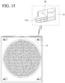
- FIGS. 14 and 15 are views illustrating a method for coupling the first hook of the first grille plate to the first hook hole of the first front panel.
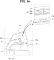
- FIGS. 16 and 17 are views illustrating a method for coupling the coupling rib of the grille cover to the first coupling groove of the first grille plate
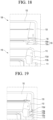
- FIGS. 18 and 19 are views illustrating a method for coupling the coupling protrusion of the grille cover to the second coupling groove of the first grille plate.
- the grille assembly 100 may be assembled on the front surface of the outdoor unit 10.
- the first grille plate 110 and the second grille plate 120 are first assembled on the front surface of the outdoor unit 10, and then the grille cover 130 can be assembled on the upper sides of the first grille plate 110 and the second grille plate 120.
- the first grille plate 110 may be first assembled on the front surface of the outdoor unit 10 and then the second grille plate 120 may be assembled.
- the second grille plate 120 may be first assembled on the front surface of the outdoor unit 10 and then the first grille plate 110 may be assembled.
- the first hook 111a of the first grille plate 110 is passed through the first hook hole 12a of the first front panel 12.
- the first hook 111a that has passed through the first hook hole 12a is pushed toward the center of the first front panel 12, so that the inner groove of the first hook 111a is inserted into the inside of the first hook hole 12a.
- the lower surface of the first hook 111a may be supported by a rib extending from the lower edge of the first hook hole 12a.
- the first grille plate 110 When the first hook 111a is coupled to the first hook hole 12a, the first grille plate 110 may be restricted from moving in the front and rear direction. In other words, when the first grille plate 110 is fixed to the first front panel 12, the movement of the first grille plate 110 in the front and rear direction may be restricted.
- the second grille plate 120 can be assembled to the second front panel 13 using the second hook 121a of the second grille plate 120.
- first hook 111a of the first grille plate 110 and the second hook 121a of the second grille plate 120 may be formed in a left-right symmetrical shape.
- the direction in which the first hook 111a is coupled to the first hook hole 12a may be opposite to the direction in which the second hook 121a is coupled to the second hook hole 13a.
- the grille cover 130 is coupled to the upper portions of the first grille plate 110 and the second grille plate 120.
- the coupling rib 134 of the grille cover 130 is coupled to the first coupling groove 112a of the first grille plate 110.
- an insertion portion 137 extending rearward from the lower end portion may be formed on the front surface portion 131 of the grille cover 130, and an insertion groove 112c for inserting the insertion portion 137 may be formed on the front end portion of the first cover portion 112.
- the grille cover 130 When the lower end portion of the grille cover 130 is inserted into the lower end portion of the first cover portion 112, the grille cover 130 is rotated so that the coupling rib 134 is inserted into the first coupling groove 112a of the first grille plate 110.
- the first rib 134a of the coupling rib 134 is supported on the upper surface of the first cover portion 112 of the first grille plate 110, and the second rib 134b of the coupling rib 134 may be engaged with the first coupling groove 112a of the first grille plate 110 in a hook manner.
- the grille cover 130 can be coupled to the second grille plate 120 using the coupling rib 134.
- the coupling protrusion 135 of the grille cover 130 is coupled to the second coupling groove 112b of the first grille plate 110.
- a portion 112d of the side of the first cover portion 112 may be inserted into the recessed portion 136 of the grille cover 130.
- the portion 112d of the side of the first cover portion 112 may be fitted into the inner space formed by the recessed portion 136 and the second protrusion 135b.
- the inner space may be formed to become narrower in width from the rear end portion to the front end portion, corresponding to the shape of the second protrusion 135b.
- the grille cover 130 can be coupled to the second grille plate 120 using the coupling protrusion 135.
- the movement of the coupling protrusion 135 in the vertical direction and the left and right direction may be restricted.
- the movement of the coupling protrusion 135 in the vertical direction and both side direction may be restricted.
- the outdoor unit of the air conditioner according to the embodiment of the present disclosure configured as described above has the following effects.
- the first grille plate, the second grille plate, and the grille cover that constitute the grille assembly can be easily assembled sequentially on the front surface of the outdoor unit, disassembly and assembly of the grille assembly are facilitated.
- the portion of the grille assembly corresponding to the front of the fan is provided with a number of ribs that form an air flow path, thereby minimizing air flow resistance to the air discharged by the fan and preventing infiltration of rainwater or foreign substances from the outside.
Landscapes
- Engineering & Computer Science (AREA)
- Mechanical Engineering (AREA)
- General Engineering & Computer Science (AREA)
- Chemical & Material Sciences (AREA)
- Combustion & Propulsion (AREA)
- Other Air-Conditioning Systems (AREA)
Abstract
An outdoor unit of an air conditioner according to the present embodiment includes: a case forming an outer appearance; a barrier dividing an inner portion of the case into a heat exchange space and an electric space; a heat exchanger disposed in the heat exchange space; a fan disposed in the heat exchange space; a compressor disposed in the electric space; and a grille assembly detachably coupled to a front surface of the case, in which the grille assembly may include: a first grille plate coupled to the front surface of the case corresponding to the front of the heat exchange space; a second grille plate coupled to the front surface of the case corresponding to the front of the electric space; and a grille cover coupled to cover an upper portion of the first grille plate and an upper portion of the second grille plate.
Description
- The present disclosure relates to an outdoor unit of an air conditioner.
- An air conditioner is a device that cools and heats an indoor space by heat exchange between a refrigerant flowing in a heat exchange cycle and indoor air and outdoor air.
- In detail, the air conditioner includes a compressor that compresses the refrigerant, an outdoor heat exchanger that exchanges heat between the refrigerant and outdoor air, and an indoor heat exchanger that exchanges heat between the refrigerant and indoor air.
- The outdoor unit of the air conditioner may include a case, the compressor and the outdoor heat exchanger accommodated inside the case, and a fan for intake and exhaust of air.
- Meanwhile, an outdoor unit cover may be provided on the outer surface of the outdoor unit to block sunlight from the outside or prevent rainwater or foreign substances from penetrating. The outdoor unit cover is installed to cover the upper surface or the side of the outdoor unit, and thus can block sunlight or prevent rainwater from penetrating.
- However, the conventional outdoor unit cover is used to simply cover the upper surface or the side surface of the outdoor unit, so it cannot protect the front surface of the outdoor unit and the overall outer appearance of the outdoor unit is poor.
- Additionally, when the outdoor unit cover is installed to cover the front surface of the outdoor unit, there is a problem in that the air forced to flow by the fan is blocked by the outdoor unit cover, resulting in air flow resistance.
- (Patent Document 1)
Korean Patent Publication No. 10-2022-0010865 (January 27, 2022
An object of the present disclosure is to provide an outdoor unit of an air conditioner that can protect the front surface of the outdoor unit. - Another object of the present disclosure is to provide an outdoor unit of an air conditioner that can have a beautiful outer appearance of the front appearance of the outdoor unit.
- Another object of the present disclosure is to provide an outdoor unit of an air conditioner that can prevent infiltration of rainwater or foreign substances from the outside.
- Another object of the present disclosure is to provide an outdoor unit of an air conditioner in which a grille assembly can be stably coupled to the front surface of the outdoor unit.
- Another object of the present disclosure is to provide an outdoor unit of an air conditioner in which the grille assembly can be easily installed and removed.
- Another object of the present disclosure is to provide an outdoor unit of an air conditioner in which air flow resistance to air discharged through a grille assembly can be minimized.
- The invention is specified by the independent claim. Preferred embodiments are defined by the dependent claims. The outdoor unit of the air conditioner according to an embodiment of the present disclosure includes a case that forms the outer appearance.
- The outdoor unit includes a barrier dividing an inner portion of the case into a heat exchange space and an electric space.
- The outdoor unit includes a heat exchanger disposed in the heat exchange space.
- The outdoor unit includes a fan disposed in the heat exchange space.
- The outdoor unit may further include a compressor disposed in the electric space.
- The outdoor unit includes a grille assembly detachably coupled to a front surface of the case.
- The grille assembly includes a first grille plate coupled to the front surface of the case corresponding to the front of the heat exchange space.
- The grille assembly includes a second grille plate coupled to the front surface of the case corresponding to the front of the electric space.
- The grille assembly includes a grille cover coupled to cover an upper portion of the first grille plate and an upper portion of the second grille plate.
- A plurality of hook holes may be formed on the front surface of the case.
- On a rear surface of the first grille plate, a first hook may be formed that is coupled to some hook holes among the plurality of hook holes
On the rear surface of the second grille plate, a second hook may be formed that is coupled to other hook holes among the plurality of hook holes. - The direction in which the first hook is coupled to some hook holes among the plurality of hook holes may be opposite to the direction in which the second hook is coupled to other hook holes among the plurality of hook holes.
- The case may include a base panel.
- The case may further include a first front panel erected on a front end portion of the base panel and forming a front surface of the heat exchange space.
- The case may further include a second front panel erected on a front end portion of the base panel and forming a front surface of the electric space.
- The first grille plate may be coupled to cover a front surface of the first front panel.
- The second grille plate may be coupled to cover a front surface of the second front panel.
- The fan may be disposed on the front of the heat exchanger.
- The first grille plate may be disposed on the front of the fan.
- The case may further include an orifice coupled to an inside of the first front panel
- The fan may be disposed on the rear of the orifice.
- The first grille plate may include a first plate coupled to the front surface of the case.
- The first grille plate may further include a first cover portion coupled to the upper end of the first plate.
- The first grille plate may further include a first grille portion provided on a front surface of the first plate.
- The first grille portion may be disposed on the front of the fan.
- The first grille portion may include a plurality of horizontal ribs spaced apart from each other in a vertical direction.
- The first grille portion may further include a plurality of longitudinal ribs that connect the plurality of horizontal ribs and are spaced apart from each other.
- The second grille plate may include a second plate coupled to the front surface of the case.
- The second grille plate may further include a second cover portion coupled to an upper end of the second plate.
- The second grille plate may further include a second grille portion provided on a front surface of the second plate.
- A front surface of the first grille portion and a front surface of the second grille portion may be disposed on the same plane.
- An upper surface of the first cover portion and an upper surface of the second cover portion may be disposed on the same plane.
- The grille cover may be coupled to cover the upper surface of the first cover portion and the upper surface of the second cover portion.
- The grille cover may include a front surface portion forming a front surface thereof.
- The grille cover may further include an upper surface portion forming an upper surface thereof.
- The grille cover may further include side portions forming both sides thereof.
- An upper portion of each of the first grille plate and the second grille plate may be inserted and accommodated inside the grille cover.
- The rear and bottom surfaces of the grille cover may be open.
- A first coupling groove may be formed on the upper surface of each of the first grille plate and the second grille plate.
- A coupling rib may be formed on the grille cover, which extends rearward from the front surface portion and is coupled to the first coupling groove.
- The coupling rib may include a first rib extending rearward from a rear surface of the front surface portion.
- The coupling rib may further include a second rib extending downward from an end portion of the first rib.
- The second rib may be engaged with an inside of the first coupling groove.
- A second coupling groove may be formed on each side of the first grille plate and the second grille plate.
- A coupling protrusion may be formed on the grille cover, which extends inward from the side portion and is coupled to the second coupling groove.
- The coupling protrusion may include a first protrusion extending from an inner surface of the side portion toward an inner center.
- The coupling protrusion may further include a second protrusion extending from the inner surface of the side portion toward the inner center and spaced upward from the first protrusion.
- An insertion groove may be formed at a front end portion of each of the first grille plate and the second grille plate.
- An insertion portion may be formed in the grille cover, which extends rearward from a lower end of the front surface portion and is coupled to the insertion groove.
-
-
FIG. 1 is a front perspective view illustrating an outdoor unit of an air conditioner according to an embodiment of the present disclosure. -
FIG. 2 is a front perspective view illustrating the outdoor unit in a state where the grille assembly is coupled according to an embodiment of the present disclosure. -
FIG. 3 is a rear perspective view illustrating the front panel in a state where the grille assembly is coupled. -
FIG. 4 is a front perspective view illustrating a first grille plate according to an embodiment of the present disclosure. -
FIG. 5 is a rear view illustrating the first grille plate. -
FIG. 6 is a top view illustrating the first grille plate. -
FIG. 7 is a front perspective view illustrating a second grille plate according to an embodiment of the present disclosure. -
FIG. 8 is a rear view illustrating the second grille plate. -
FIG. 9 is a top view illustrating the second grille plate. -
FIG. 10 is a front perspective view illustrating a grille cover according to an embodiment of the present disclosure. -
FIG. 11 is a rear view of the grille cover illustrating a portion of the rear of the grille cover. -
FIG. 12 is a bottom view illustrating the grille cover. -
FIG. 13 is a view illustrating the assembly sequence of the grille assembly. -
FIGS. 14 and15 are views illustrating a method for coupling the first hook of the first grille plate to the first hook hole of the first front panel. -
FIGS. 16 and17 are views illustrating a method for coupling the coupling rib of the grille cover to the first coupling groove of the first grille plate. -
FIGS. 18 and 19 are views illustrating a method for coupling the coupling protrusion of the grille cover to the second coupling groove of the first grille plate. - Reference will now be made in detail to the embodiments of the present disclosure, examples of which are illustrated in the accompanying drawings.
- In the following detailed description of the preferred embodiments, reference is made to the accompanying drawings that form a part hereof, and in which is shown by way of illustration specific preferred embodiments in which the disclosure may be practiced. These embodiments are described in sufficient detail to enable those skilled in the art to practice the disclosure, and it is understood that other embodiments may be utilized and that logical structural, mechanical, electrical, and chemical changes may be made without departing from the scope of the disclosure. To avoid detail not necessary to enable those skilled in the art to practice the disclosure, the description may omit certain information known to those skilled in the art. The following detailed description is, therefore, not to be taken in a limiting sense.
- Also, in the description of embodiments, terms such as first, second, A, B, (a), (b) or the like may be used herein when describing components of the present disclosure. Each of these terminologies is not used to define an essence, order or sequence of a corresponding component but used merely to distinguish the corresponding component from other component(s). It should be noted that if it is described in the specification that one component is "connected," "coupled" or "joined" to another component, the former may be directly "connected," "coupled," and "joined" to the latter or "connected", "coupled", and "joined" to the latter via another component.
-
FIG. 1 is a front perspective view illustrating an outdoor unit of an air conditioner according to an embodiment of the present disclosure, andFIG. 2 is a front perspective view illustrating the outdoor unit in a state where the grille assembly is coupled according to an embodiment of the present disclosure. - Referring to
FIGS. 1 and 2 , theoutdoor unit 10 of an air conditioner according to an embodiment of the present disclosure includes a case that forms an outer appearance of the outdoor unit. - The case may include a
base panel 11 forming the bottom surface of theoutdoor unit 10, a firstfront panel 12 erected on one side of the front end portion of thebase panel 11, and a secondfront panel 13 erected on the other side of the front end portion of thebase panel 11. - The case may further include a
side panel 14 erected on the side of thebase panel 11 and atop panel 15 forming the upper surface of theoutdoor unit 10. - The
outdoor unit 10 may further include anorifice 16 coupled to the firstfront panel 12, afan 17 disposed behind theorifice 16, and a heat exchanger erected on the upper surface of thebase panel 11. Thefan 17 may be disposed on the front of the heat exchanger. - The
outdoor unit 10 may further include a barrier erected on the upper surface of thebase panel 11. - The barrier can divide the upper space of the
base panel 11 into a heat exchange space on the left and an electric space on the right. The heat exchanger may be disposed in the heat exchange space. The heat exchanger may be bent and extended along the side and rear end portions of thebase panel 11 to define the side and the rear surface of the heat exchange space. - One side end portion of the first
front panel 12 may be coupled to the front end portion of the heat exchanger, and the other side end portion may be coupled to the front end portion of the barrier. The rear end portion of the barrier may be connected to the side end portion of the heat exchanger. - The
outdoor unit 10 may further include a compressor and a heat storage tank erected on the upper surface of thebase panel 11 corresponding to the electric space. - The refrigerant that has passed through the heat storage tank may be guided to the heat exchanger along the refrigerant pipe. The refrigerant that has passed through the heat exchanger may pass through an expansion valve and then be guided to the heat exchanger of the indoor unit. The refrigerant that has passed through the indoor unit may pass through a gas-liquid separator and then be recovered by the compressor.
- When the
fan 17 rotates, outdoor air is introduced into theoutdoor unit 10 through the short side portion of the heat exchanger forming the side of theoutdoor unit 10 and the long side portion of the heat exchanger forming the rear surface of theoutdoor unit 10. - The air that has passed through the heat exchanger flows from the rear surface to the front surface of the
fan 17, passes through theorifice 16, and then can be discharged to the outside of theoutdoor unit 10. - A portion of the plurality of blades constituting the
fan 17 can be accommodated inside theorifice 16 so that all air forced to flow by thefan 17 passes through theorifice 16. - The
outdoor unit 10 may further include agrille assembly 100 detachably coupled to the front surface of theoutdoor unit 10. - The
grille assembly 100 is installed on the front surface of theoutdoor unit 10 to protect the front surface of theoutdoor unit 10. Thegrille assembly 100 can block rainwater or foreign substances introduced into the front surface of theoutdoor unit 10 from the outside. Thegrille assembly 100 can cover the entire front surface of theoutdoor unit 10 to improve the outer appearance of the front surface of theoutdoor unit 10. - The
grille assembly 100 may include afirst grille plate 110, asecond grille plate 120, and agrille cover 130 coupled to the front surface of theoutdoor unit 10. - The
first grille plate 110 may be coupled to the front surface of theoutdoor unit 10 and cover a portion of the front surface of theoutdoor unit 10. Thefirst grille plate 110 may be detachably coupled to the front surface of the firstfront panel 12. Thefirst grille plate 110 may cover a portion of theorifice 16 where thefan 17 is accommodated. - The
second grille plate 120 may be coupled to the front surface of theoutdoor unit 10 and cover another portion of the front surface of theoutdoor unit 10. Thesecond grille plate 120 may be detachably coupled to the front surface of the secondfront panel 13. Thesecond grille plate 120 may be disposed on a side of thefirst grille plate 110. - The
first grille plate 110 and thesecond grille plate 120 may be connected to each other. Thefirst grille plate 110 and thesecond grille plate 120 may be disposed side by side in the left and right direction on the front surface of theoutdoor unit 10. The front surface of thefirst grille plate 110 and the front surface of thesecond grille plate 120 may be disposed on the same plane. - The
grille cover 130 is coupled to thefirst grille plate 110 and thesecond grille plate 120, and has a function of fixing thefirst grille plate 110 and thesecond grille plate 120. Thegrille cover 130 may be coupled to the upper portion of thefirst grille plate 110 and the upper portion of thesecond grille plate 120. - The
grille cover 130 may be coupled to cover the upper portion of thefirst grille plate 110 and the upper portion of thesecond grille plate 120. Thegrille cover 130 may be disposed on the upper end of the front surface of theoutdoor unit 10. A portion of thegrille cover 130 may be disposed on the upper end of the firstfront panel 12, and another portion of thegrille cover 130 may be disposed on the upper end of the secondfront panel 13. - Hereinafter, the first grille plate, the second grille plate, and the grille cover according to an embodiment of the present disclosure will be described in detail with reference to the drawings.
-
FIG. 3 is a rear perspective view illustrating the front panel in a state where the grille assembly is coupled,FIG. 4 is a front perspective view illustrating a first grille plate according to an embodiment of the present disclosure,FIG. 5 is a rear view illustrating the first grille plate, andFIG. 6 is a top view illustrating the first grille plate. - Referring to
FIGS. 3 to 6 , thefirst grille plate 110 may be coupled to the front surface of the firstfront panel 12 and cover the front surface of the firstfront panel 12. - The
first grille plate 110 may have a shape corresponding to the shape of the front surface of the firstfront panel 12. For example, thefirst grille plate 110 may have a square panel shape. - The
first grille plate 110 may include afirst plate 111 coupled to the front surface of the firstfront panel 12, afirst cover portion 112 coupled to the upper end of thefirst plate 111, and afirst grille portion 113 provided on the front surface of thefirst plate 111. - The
first plate 111 may define both sides and the rear surface of thefirst grille plate 110, thefirst cover portion 112 may define the upper surface of thefirst grille plate 110, and thefirst cover portion 112 may define the front surface of thefirst grille plate 113. - The
first plate 111 is formed in a shape corresponding to the front surface of the firstfront panel 12 and can be coupled to the front surface of the firstfront panel 12. Thefirst plate 111 may be formed as a square panel with a constant thickness in the front and rear direction. - The
first plate 111 may include afirst hook 111a to be coupled to the firstfront panel 12. - The
first hook 111a may be formed to extend rearward from the rear surface of thefirst plate 111. A plurality offirst hooks 111a may be formed on the rear surface of thefirst plate 111. The plurality offirst hooks 111a may be disposed to be spaced apart along the rear edge of thefirst plate 111. - The
first hook 111a may be inserted into and fastened to thefirst hook hole 12a formed in the firstfront panel 12. - The
first hook hole 12a may be formed to penetrate from the front surface to the rear surface of the firstfront panel 12. Thefirst hook hole 12a may be formed at an edge of the firstfront panel 12. A plurality offirst hook holes 12a may be formed to be spaced apart from each other along the edge of the firstfront panel 12. - The
first plate 111 may further include a through-hole 111b formed at a point corresponding to theorifice 16 of the firstfront panel 12. - The through-
hole 111b may be formed in the center of thefirst plate 111. The through-hole 11 1b may be formed by penetrating from the front surface to the rear surface of thefirst plate 111. - The through-
hole 111b may be formed in a shape corresponding to theorifice 16. The through-hole 111b is disposed to face theorifice 16, so that air passing through theorifice 16 can be discharged to the outside of theoutdoor unit 10 through thefirst grille portion 113. - The
first cover portion 112 may be mounted on the upper surface of thefirst plate 111. - For example, the
first cover portion 112 may be formed in a plate shape that is narrow in the front and rear direction and long in the left and right direction. Thefirst cover portion 112 may be coupled to the upper end of thefirst plate 111. When thefirst cover portion 112 is coupled to thefirst plate 111, the upper surface of thefirst plate 111 may be covered by thefirst cover portion 112. - The
first cover portion 112 may include afirst coupling groove 112a for being coupled to thegrille cover 130. - The
first coupling groove 112a may be formed on the upper surface of thefirst cover portion 112. Thefirst coupling groove 112a may be formed by cutting a portion of the upper surface of thefirst cover portion 112. A plurality offirst coupling grooves 112a may be formed. The plurality offirst coupling grooves 112a may be disposed to be spaced apart in the longitudinal direction on the upper surface of thefirst cover portion 112. - The
first cover portion 112 may further include asecond coupling groove 112b for being coupled to thegrille cover 130. - The
second coupling groove 112b may be formed on the side of thefirst cover portion 112. Thesecond coupling groove 112b may be formed by recessing a portion of the side of thefirst cover portion 112. Thesecond coupling groove 112b may be formed on one of both sides of thefirst cover portion 112. For example, thesecond coupling groove 112b may be formed on the left side of both sides of thefirst cover portion 112. - The
first grille portion 113 may include a plurality of ribs to form a grille shape. Thefirst grille portion 113 may be provided on the front surface of thefirst plate 111. Thefirst grille portion 113 may protrude from the inside to the front surface of thefirst plate 111. - The
first grille portion 113 may include a plurality ofhorizontal ribs 113a extending in the horizontal direction and a plurality oflongitudinal ribs 113b extending in the vertical direction. - The plurality of
horizontal ribs 113a may be formed entirely on the front surface of thefirst plate 111. The plurality ofhorizontal ribs 113a may be disposed to be spaced apart in the vertical direction on the front surface of thefirst plate 111. The plurality ofhorizontal ribs 113a may be spaced apart from each other at equal intervals. - The plurality of
longitudinal ribs 113b may be formed on a portion of the front surface of thefirst plate 111. For example, the plurality oflongitudinal ribs 113b may be provided in a corresponding area of thefirst plate 111 facing the through-hole 111b. The plurality oflongitudinal ribs 113b may be disposed to cover the through-hole 111b. - The plurality of
longitudinal ribs 113b may be formed only in the area of the circular flow path portion forming the air flow path. The plurality oflongitudinal ribs 113b may be disposed to connect two adjacenthorizontal ribs 113a. The plurality oflongitudinal ribs 113b may be disposed at irregular intervals between the plurality ofhorizontal ribs 113a. - Due to the configuration of the
horizontal ribs 113a and thelongitudinal ribs 113b, exposure of thefan 17 to the outside of theoutdoor unit 10 can be minimized. In addition, since thehorizontal ribs 113a andlongitudinal ribs 113b cover theorifice 16 where thefan 17 is accommodated, it is possible to prevent rainwater or foreign substances from penetrating from the outside. -
FIG. 7 is a front perspective view illustrating a second grille plate according to an embodiment of the present disclosure,FIG. 8 is a rear view illustrating the second grille plate, andFIG. 9 is a top view illustrating the second grille plate. - Referring to
FIGS. 3 ,7 to 9 , thesecond grille plate 120 may be coupled to the front surface of the secondfront panel 13 and cover the front surface of the secondfront panel 13. - The
second grille plate 120 may have a shape corresponding to the shape of the front surface of the secondfront panel 13. For example, thesecond grille plate 120 may have a square panel shape. - In this embodiment, the
second grille plate 120 may be formed smaller than thefirst grille plate 110. However, it is not limited to this, and when the secondfront panel 13 is formed larger than the firstfront panel 12, thesecond grille plate 120 may be formed larger than thefirst grille plate 110. - The
second grille plate 120 may include asecond plate 121 coupled to the front surface of the secondfront panel 13, asecond cover portion 122 coupled to the upper end of thesecond plate 121, and asecond grille portion 123 provided on the front surface of thesecond plate 121. - The
second plate 121 defines both sides and the rear surface of thesecond grille plate 120, thesecond cover portion 122 defines the upper surface of thesecond grille plate 120, and thesecond grille portion 123 may define the front surface of thesecond grille plate 123. - The
second plate 121 is formed in a shape corresponding to the front surface of the secondfront panel 13 and can be coupled to the front surface of the secondfront panel 13. Thesecond plate 121 may be formed as a square panel with a constant thickness in the front and rear direction. - The thickness of the
second plate 121 may be formed to be the same as the thickness of thefirst plate 111. - The
second plate 121 may include asecond hook 121a to be coupled to the secondfront panel 13. - The
second hook 121a may be formed to extend rearward from the rear surface of thesecond plate 121. A plurality ofsecond hooks 121a may be formed on the rear surface of thesecond plate 121. The plurality ofsecond hooks 121a may be disposed to be spaced apart along the rear edge of thesecond plate 121. - The
second hook 121a may be inserted into and fastened to thesecond hook hole 13a formed in the secondfront panel 13. - The
second hook hole 12a may be formed to penetrate from the front surface to the rear surface of the secondfront panel 13. Thesecond hook hole 13a may be formed at the edge of the secondfront panel 13. A plurality ofsecond hook holes 13a may be formed to be spaced apart along the edge of the secondfront panel 13. - The
second cover portion 122 may be mounted on the upper surface of thesecond plate 121. Thesecond cover portion 122 may be formed to correspond to the shape of thefirst cover portion 112. - For example, the
second cover portion 122 may be formed in a plate shape that is narrow in the front and rear direction and long in the left and right direction. Thesecond cover portion 122 may be coupled to the upper end of thesecond plate 121. When thesecond cover portion 122 is coupled to thesecond plate 121, the upper surface of thesecond plate 121 may be covered by thesecond cover portion 122. - The
second cover portion 122 may include afirst coupling groove 122a for being coupled to thegrille cover 130. Thefirst coupling groove 122a of thesecond cover portion 122 may be formed to correspond to the shape of thefirst coupling groove 112a of thefirst cover portion 112. - The
first coupling groove 122a may be formed on the upper surface of thesecond cover portion 122. Thefirst coupling groove 122a may be formed by cutting a portion of the upper surface of thesecond cover portion 122. A plurality offirst coupling grooves 122a may be formed. The plurality offirst coupling grooves 122a may be disposed to be spaced apart in the longitudinal direction on the upper surface of thesecond cover portion 122. - The
second cover portion 122 may further include asecond coupling groove 122b for being coupled to thegrille cover 130. Thesecond coupling groove 122b of thesecond cover portion 122 may be formed to correspond to the shape of thesecond coupling groove 112b of thefirst cover portion 112. - The
second coupling groove 122b may be formed on the side of thesecond cover portion 122. Thesecond coupling groove 122b may be formed by recessing a portion of the side of thesecond cover portion 122. Thesecond coupling groove 122b may be formed on one of both sides of thesecond cover portion 122. For example, thesecond coupling groove 122b may be formed on the right side of both sides of thesecond cover portion 122. - The
second grille portion 123 may include a plurality of ribs to form a grille shape. Thesecond grille portion 123 may be provided on the front surface of thesecond plate 121. Thesecond grille portion 123 may protrude from the inside to the front surface of thesecond plate 121. - The
second grille portion 123 may include a plurality of horizontal ribs extending in the horizontal direction. - The plurality of horizontal ribs may be formed entirely on the front surface of the
second plate 121. The plurality of horizontal ribs may be disposed to be spaced apart in the vertical direction on the front surface of thesecond plate 121. The plurality of horizontal ribs may be spaced apart from each other at equal intervals. - The upper surface of the
first cover portion 112 and the upper surface of thesecond cover portion 122 may be disposed on the same plane. Thegrille cover 130 may be coupled to cover the upper surface of thefirst cover portion 112 and the upper surface of thesecond cover portion 122. - The front surface of the
first grille portion 113 and the front surface of thesecond grille portion 123 may be disposed on the same plane. -
FIG. 10 is a front perspective view illustrating a grille cover according to an embodiment of the present disclosure,FIG. 11 is a rear view of the grille cover illustrating a portion of the rear of the grille cover, andFIG. 12 is a bottom view illustrating the grille cover. - Referring to
FIGS. 2 ,10 to 12 , thegrille cover 130 may be coupled and fixed to the upper portions of thefirst grille plate 110 and thesecond grille plate 120, respectively. - The
grille cover 130 may be narrow in the front and rear direction and long in the left and right direction. Thegrille cover 130 may be formed in the shape of a rod or stick extending in the left and right direction. - For example, the
grille cover 130 may include afront surface portion 131 forming the front surface, anupper surface portion 132 forming the upper surface, andside portions 133 forming both sides. The front surface, upper surface, and both sides of thegrille cover 130 may be closed, and the rear surface and the lower surface may be open. At least a portion of theupper surface 132 of thegrille cover 130 may be formed to be inclined. - The
grille cover 130 may further include a plurality ofcoupling ribs 134 to be coupled to thefirst grille plate 110 and thesecond grille plate 120. - The plurality of
coupling ribs 134 may be formed to extend inward from the inner surface of thegrille cover 130. The plurality ofcoupling ribs 134 may be disposed to be spaced apart from each other in the longitudinal direction of thegrille cover 130 on the inner surface of thegrille cover 130. - Some of the plurality of
coupling ribs 134 are coupled to thefirst coupling groove 112a of thefirst grille plate 110, and some of the remainingcoupling ribs 134 are coupled to thefirst coupling groove 122a of the second grille plate 1210. - In this embodiment, the
coupling ribs 134 are comprised of a total of six, with threecoupling ribs 134 coupled to thefirst grille plate 110 and the remaining threecoupling ribs 134 being coupled to thesecond grille plate 120. - However, it is not limited to this, and the number of
coupling ribs 134 may vary according to the number of thefirst coupling groove 112a of thefirst grille plate 110 and thefirst coupling groove 122a of thesecond grille plate 120. - The plurality of
coupling ribs 134 may include afirst rib 134a extending rearward from thefront surface portion 131 of thegrille cover 130, and asecond rib 134b extending downward from thefirst rib 134a, respectively. - The
first rib 134a may extend rearward from the rear surface of thefront surface portion 131 of thegrille cover 130. Thefirst rib 134a may extend horizontally to the ground to face theupper surface portion 132 of thegrille cover 130. - The
second rib 134b may extend downward from the end portion of thefirst rib 134a. Thesecond rib 134b may extend vertically from the rear end portion of thefirst rib 134a. - Some of the
first ribs 134a of the plurality ofcoupling ribs 134 are supported on the upper surface of thefirst cover portion 112 of thefirst grille plate 110, and some of thesecond ribs 134b of the plurality ofcoupling ribs 134 may be inserted into thefirst coupling groove 112a of thefirst grille plate 110. Thesecond rib 134b may be engaged to the inside of thefirst coupling groove 112a. - When the
second rib 134b is coupled to thefirst coupling groove 112a, forward movement of thesecond rib 134b may be restricted. In other words, when thegrille cover 130 is fixed to thefirst grille plate 110, movement in the front and rear direction may be restricted. - The
first ribs 134a of the remaining portion of the plurality ofcoupling ribs 134 are supported on the upper surface of thesecond cover portion 122 of thesecond grille plate 120, and thesecond ribs 134b of the remaining portion of the plurality ofcoupling ribs 134 may be inserted into thefirst coupling groove 122a of thesecond grille plate 120. Thesecond rib 134b may be engaged to the inside of thefirst coupling groove 122a using a hook method. - When the
second rib 134b is coupled to thefirst coupling groove 122a, forward movement of thesecond rib 134b may be restricted. In other words, when thegrille cover 130 is fixed to thesecond grille plate 120, movement in the front and rear direction may be restricted. - Additionally, the
grille cover 130 may further include acoupling protrusion 135 to be coupled to thefirst grille plate 110 and thesecond grille plate 120. - The
coupling protrusion 135 may be formed to protrude inward from theside portion 133 of thegrille cover 130. The coupling protrusions 135 may be formed on oneside portion 133 and theother side portion 133 of thegrille cover 130, respectively. - The
coupling protrusion 135 formed on oneside portion 133 of thegrille cover 130 is coupled to thesecond coupling groove 112b of thefirst grille plate 110 and thecoupling protrusion 135 formed on theother side portion 133 of thegrille cover 130 may be coupled to thesecond coupling groove 122b of thesecond grille plate 120. - The
coupling protrusion 135 may include afirst protrusion 135a protruding inward from theside portion 133 of thegrille cover 130. Thecoupling protrusion 135 may further include asecond protrusion 135b protruding inward from theside portion 133 of thegrille cover 130. - The
first protrusion 135a may protrude from the inner surface of theside portion 133 of thegrille cover 130 toward the inner center. Thefirst protrusion 135a may be formed at the lower end portion of theside portion 133 of thegrille cover 130. - The
second protrusion 135b may protrude from the inner surface of theside portion 133 of thegrille cover 130 toward the inner center. Thesecond protrusion 135b may be disposed to be spaced upward from thefirst protrusion 135a. Thefirst protrusion 135a and thesecond protrusion 135b may be spaced apart in the vertical direction. - The
first protrusion 135a may protrude further inward than thesecond protrusion 135b. The length of the portion where thefirst protrusion 135a protrudes in the inward direction may be formed to be longer than the length of the portion where thesecond protrusion 135b protrudes in the inward direction. - The
first protrusion 135a and thesecond protrusion 135b may extend from theside portion 133 of thegrille cover 130 in the front and rear direction, respectively. - The
second protrusion 135b may be formed to increase in width or thickness from the rear end portion to the front end portion. In other words, the width or thickness of the front end portion of thesecond protrusion 135b may be greater than the width or thickness of the rear end portion of thesecond protrusion 135b. - The
first protrusion 135a and thesecond protrusion 135b formed on oneside portion 133 of thegrille cover 130 may be received and coupled to thesecond coupling groove 112b of thefirst grille plate 110, and thefirst protrusion 135a and thesecond protrusion 135b formed on theother side portion 133 of thegrille cover 130 may be received and coupled to thesecond coupling groove 122b of thesecond grille plate 120. - When the
coupling protrusion 135 is coupled to thesecond coupling grooves coupling protrusion 135 in the vertical direction and in the left and right direction may be restricted. That is, when thegrille cover 130 is fixed to thefirst grille plate 110 and thesecond grille plate 120, movement in the vertical direction and the left and right directions may be restricted. - The
grille cover 130 may further include a recessedportion 136 that is recessed in theside portion 133 of thegrille cover 130. - The recessed
portion 136 may be formed by being recessed from the inner surface of the side portion thegrille cover 130 toward the outside. The recessedportion 136 may extend from thegrille cover 130 in the front and rear direction. - The
second protrusion 135b may be formed in the recessedportion 136. Thesecond protrusion 135b may protrude from thedepression 136 toward the inner center. - Hereinafter, the assembly sequence of the grille assembly will be described in detail with reference to the drawings.
-
FIG. 13 is a view illustrating the assembly sequence of the grille assembly, andFIGS. 14 and15 are views illustrating a method for coupling the first hook of the first grille plate to the first hook hole of the first front panel. -
FIGS. 16 and17 are views illustrating a method for coupling the coupling rib of the grille cover to the first coupling groove of the first grille plate, andFIGS. 18 and 19 are views illustrating a method for coupling the coupling protrusion of the grille cover to the second coupling groove of the first grille plate. - Referring to
FIG. 13 , as described above, thegrille assembly 100 may be assembled on the front surface of theoutdoor unit 10. - The
first grille plate 110 and thesecond grille plate 120 are first assembled on the front surface of theoutdoor unit 10, and then thegrille cover 130 can be assembled on the upper sides of thefirst grille plate 110 and thesecond grille plate 120. - The
first grille plate 110 may be first assembled on the front surface of theoutdoor unit 10 and then thesecond grille plate 120 may be assembled. Alternatively, thesecond grille plate 120 may be first assembled on the front surface of theoutdoor unit 10 and then thefirst grille plate 110 may be assembled. - Referring to
FIGS. 14 and15 , after positioning thefirst grille plate 110 in the front of the firstfront panel 12, thefirst hook 111a of thefirst grille plate 110 is passed through thefirst hook hole 12a of the firstfront panel 12. - Then, the
first hook 111a that has passed through thefirst hook hole 12a is pushed toward the center of the firstfront panel 12, so that the inner groove of thefirst hook 111a is inserted into the inside of thefirst hook hole 12a. - When the
first hook 111a is completely coupled to thefirst hook hole 12a, the lower surface of thefirst hook 111a may be supported by a rib extending from the lower edge of thefirst hook hole 12a. - When the
first hook 111a is coupled to thefirst hook hole 12a, thefirst grille plate 110 may be restricted from moving in the front and rear direction. In other words, when thefirst grille plate 110 is fixed to the firstfront panel 12, the movement of thefirst grille plate 110 in the front and rear direction may be restricted. - In the same way, after placing the
second grille plate 120 in the front of the secondfront panel 13, thesecond grille plate 120 can be assembled to the secondfront panel 13 using thesecond hook 121a of thesecond grille plate 120. - However, the
first hook 111a of thefirst grille plate 110 and thesecond hook 121a of thesecond grille plate 120 may be formed in a left-right symmetrical shape. - The direction in which the
first hook 111a is coupled to thefirst hook hole 12a may be opposite to the direction in which thesecond hook 121a is coupled to thesecond hook hole 13a. - Referring to
FIGS. 16 and17 , in a state where thefirst grille plate 110 and thesecond grille plate 120 are assembled to theoutdoor unit 10, thegrille cover 130 is coupled to the upper portions of thefirst grille plate 110 and thesecond grille plate 120. - Specifically, after inserting the lower end portion of the
grille cover 130 into the lower end portion of thefirst cover portion 112, thecoupling rib 134 of thegrille cover 130 is coupled to thefirst coupling groove 112a of thefirst grille plate 110. - At this time, an
insertion portion 137 extending rearward from the lower end portion may be formed on thefront surface portion 131 of thegrille cover 130, and aninsertion groove 112c for inserting theinsertion portion 137 may be formed on the front end portion of thefirst cover portion 112. - When the lower end portion of the
grille cover 130 is inserted into the lower end portion of thefirst cover portion 112, thegrille cover 130 is rotated so that thecoupling rib 134 is inserted into thefirst coupling groove 112a of thefirst grille plate 110. - At this time, the
first rib 134a of thecoupling rib 134 is supported on the upper surface of thefirst cover portion 112 of thefirst grille plate 110, and thesecond rib 134b of thecoupling rib 134 may be engaged with thefirst coupling groove 112a of thefirst grille plate 110 in a hook manner. - In a state where the
second rib 134b is coupled to thefirst coupling groove 112a, forward movement of thesecond rib 134b may be restricted. In other words, in a state where thegrille cover 130 is fixed to thefirst grille plate 110, the movement of the first grille plate in the front and rear direction may be restricted. - In the same way, the
grille cover 130 can be coupled to thesecond grille plate 120 using thecoupling rib 134. - Referring to
FIGS. 18 and 19 , thecoupling protrusion 135 of thegrille cover 130 is coupled to thesecond coupling groove 112b of thefirst grille plate 110. - When the
coupling protrusion 135 is inserted into thesecond coupling groove 112b, aportion 112d of the side of thefirst cover portion 112 may be inserted into the recessedportion 136 of thegrille cover 130. Specifically, theportion 112d of the side of thefirst cover portion 112 may be fitted into the inner space formed by the recessedportion 136 and thesecond protrusion 135b. The inner space may be formed to become narrower in width from the rear end portion to the front end portion, corresponding to the shape of thesecond protrusion 135b. - In the same way, the
grille cover 130 can be coupled to thesecond grille plate 120 using thecoupling protrusion 135. - In a state where the
coupling protrusion 135 is coupled to thesecond coupling grooves coupling protrusion 135 in the vertical direction and the left and right direction may be restricted. In other words, in a state where thegrille cover 130 is fixed to thefirst grille plate 110 and thesecond grille plate 120, the movement of thecoupling protrusion 135 in the vertical direction and both side direction may be restricted. - The outdoor unit of the air conditioner according to the embodiment of the present disclosure configured as described above has the following effects.
- First, since a grille assembly is provided that covers the entire front surface of the outdoor unit, the front surface of the outdoor unit is protected and the outer appearance of the front surface of the outdoor unit is improved.
- Second, since the first grille plate, the second grille plate, and the grille cover that constitute the grille assembly can be easily assembled sequentially on the front surface of the outdoor unit, disassembly and assembly of the grille assembly are facilitated.
- Third, the portion of the grille assembly corresponding to the front of the fan is provided with a number of ribs that form an air flow path, thereby minimizing air flow resistance to the air discharged by the fan and preventing infiltration of rainwater or foreign substances from the outside.
- Fourth, in a state where the first grille plate and the second grille plate are coupled to the front surface of the outdoor unit, multiple coupling portions of the grille cover can be coupled to the first grille plate and the second grille plate, respectively, so that the grille assembly can be stably coupled to the outdoor unit.
Claims (15)
- An outdoor unit of an air conditioner comprising:a case forming an outer appearance;a barrier dividing an inner portion of the case into a heat exchange space and an electric space;a heat exchanger disposed in the heat exchange space;a grille assembly (100) detachably coupled to a front surface of the case,wherein the grille assembly (100) includes:a first grille plate (110) coupled to the front surface of the case corresponding to a front of the heat exchange space;a second grille plate (120) coupled to the front surface of the case corresponding to a front of the electric space; anda grille cover (130) coupled to cover an upper portion of the first grille plate (110) and an upper portion of the second grille plate (120).
- The outdoor unit of an air conditioner of claim 1,wherein a plurality of hook holes (12a, 13a) is formed on the front surface of the case,wherein, on a rear surface of the first grille plate (110), a first hook (111a) is formed that is coupled to some hook holes among the plurality of hook holes (12a, 13a), andwherein, on the rear surface of the second grille plate (120), a second hook (121a) is formed that is coupled to other hook holes among the plurality of hook holes (12a, 13a).
- The outdoor unit of an air conditioner of claim 2, wherein the direction in which the first hook (111a) is coupled to some hook holes among the plurality of hook holes (12a, 13a) is opposite to the direction in which the second hook (121a) is coupled to other hook holes among the plurality of hook holes (12a, 13a).
- The outdoor unit of an air conditioner of any one of claims 1 to 3, wherein the case includes:a base panel (11);a first front panel (12) erected on a front end portion of the base panel (11) and forming a front surface of the heat exchange space; anda second front panel (13) erected on another front end portion of the base panel (11) and forming a front surface of the electric space.
- The outdoor unit of an air conditioner of claim 4,wherein the first grille plate (110) is coupled to cover a front surface of the first front panel (12), andwherein the second grille plate (120) is coupled to cover a front surface of the second front panel (13).
- The outdoor unit of an air conditioner of any one of claims 1 to 5,further comprising a fan (17) disposed in the heat exchange space;wherein the fan (17) is disposed on a front of the heat exchanger, andwherein the first grille plate (110) is disposed on a front of the fan (17).
- The outdoor unit of an air conditioner of any one of claims 4 to 6,wherein the case further includes an orifice (16) coupled to an inside of the first front panel (12), andwherein the fan (17) is disposed on a rear of the orifice (16).
- The outdoor unit of an air conditioner of claim 6 or 7, wherein the first grille plate (110) includes:a first plate (111) coupled to the front surface of the case;a first cover portion (112) coupled to an upper end of the first plate (111); anda first grille portion (113) provided on a front surface of the first plate (111), andwherein the first grille portion (113) is disposed on the front of the fan (17).
- The outdoor unit of an air conditioner of claim 8, wherein the first grille portion (113) includes:a plurality of horizontal ribs (113a) spaced apart from each other in a vertical direction; anda plurality of longitudinal ribs (113b) that connect the plurality of horizontal ribs (113a) and are spaced apart from each other.
- The outdoor unit of an air conditioner of claim 8 or 9, wherein the second grille plate (120) includes:a second plate (121) coupled to the front surface of the case;a second cover portion (122) coupled to an upper end of the second plate (121); anda second grille portion (123) provided on a front surface of the second plate (121), andwherein a front surface of the first grille portion (113) and a front surface of the second grille portion (123) are disposed on a same plane.
- The outdoor unit of an air conditioner of claim 10,wherein an upper surface of the first cover portion (112) and an upper surface of the second cover portion (122) are disposed on the same plane, andwherein the grille cover (130) is coupled to cover the upper surface of the first cover portion (112) and the upper surface of the second cover portion (122).
- The outdoor unit of an air conditioner of any one of claims 1 to 11, wherein the grille cover (130) includes:a front surface portion (131) forming a front surface thereof;an upper surface portion (132) forming an upper surface thereof; andside portions (133) forming both sides thereof, andwherein an upper portion of each of the first grille plate (110) and the second grille plate (120) is inserted and accommodated inside the grille cover (130).
- The outdoor unit of an air conditioner of any one of claims 1 to 12, wherein a rear surface and a bottom surface of the grille cover (130) are open.
- The outdoor unit of an air conditioner of claim 12 or 13,wherein a first coupling groove (112a) is formed on the upper surface of each of the first grille plate (110) and the second grille plate (120), andwherein a coupling rib (134) is formed on the grille cover (130), which extends rearward from the front surface portion (131) and is coupled to the first coupling groove (112a).
- The outdoor unit of an air conditioner of claim 14, wherein the coupling rib (134) includes:a first rib (134a) extending rearward from a rear surface of the front surface portion (131); anda second rib (134b) extending downward from an end portion of the first rib (134a), andwherein the second rib (134b) is engaged with an inside of the first coupling groove (112a).
Applications Claiming Priority (1)
| Application Number | Priority Date | Filing Date | Title |
|---|---|---|---|
| KR1020230102253A KR20250020914A (en) | 2023-08-04 | 2023-08-04 | An outdoor unit of air conditioner |
Publications (1)
| Publication Number | Publication Date |
|---|---|
| EP4502477A1 true EP4502477A1 (en) | 2025-02-05 |
Family
ID=89619149
Family Applications (1)
| Application Number | Title | Priority Date | Filing Date |
|---|---|---|---|
| EP24151440.5A Pending EP4502477A1 (en) | 2023-08-04 | 2024-01-11 | An outdoor unit of air conditioner |
Country Status (3)
| Country | Link |
|---|---|
| US (1) | US20250043987A1 (en) |
| EP (1) | EP4502477A1 (en) |
| KR (1) | KR20250020914A (en) |
Citations (4)
| Publication number | Priority date | Publication date | Assignee | Title |
|---|---|---|---|---|
| EP3587941A1 (en) * | 2017-02-23 | 2020-01-01 | Mitsubishi Electric Corporation | Outdoor unit for air conditioner |
| EP3705731A1 (en) * | 2019-03-08 | 2020-09-09 | Daikin Industries, Ltd. | Outdoor unit for a heat pump having a grille made of separate parts |
| EP4102143A1 (en) * | 2021-06-07 | 2022-12-14 | Panasonic Intellectual Property Management Co., Ltd. | Heat pump heat source device |
| US20230243524A1 (en) * | 2022-01-28 | 2023-08-03 | Samsung Electronics Co., Ltd. | Outdoor unit of airconditioner |
Family Cites Families (1)
| Publication number | Priority date | Publication date | Assignee | Title |
|---|---|---|---|---|
| KR102913913B1 (en) | 2020-07-20 | 2026-01-15 | 엘지전자 주식회사 | Heat pump |
-
2023
- 2023-08-04 KR KR1020230102253A patent/KR20250020914A/en active Pending
-
2024
- 2024-01-02 US US18/401,937 patent/US20250043987A1/en active Pending
- 2024-01-11 EP EP24151440.5A patent/EP4502477A1/en active Pending
Patent Citations (4)
| Publication number | Priority date | Publication date | Assignee | Title |
|---|---|---|---|---|
| EP3587941A1 (en) * | 2017-02-23 | 2020-01-01 | Mitsubishi Electric Corporation | Outdoor unit for air conditioner |
| EP3705731A1 (en) * | 2019-03-08 | 2020-09-09 | Daikin Industries, Ltd. | Outdoor unit for a heat pump having a grille made of separate parts |
| EP4102143A1 (en) * | 2021-06-07 | 2022-12-14 | Panasonic Intellectual Property Management Co., Ltd. | Heat pump heat source device |
| US20230243524A1 (en) * | 2022-01-28 | 2023-08-03 | Samsung Electronics Co., Ltd. | Outdoor unit of airconditioner |
Also Published As
| Publication number | Publication date |
|---|---|
| US20250043987A1 (en) | 2025-02-06 |
| KR20250020914A (en) | 2025-02-11 |
Similar Documents
| Publication | Publication Date | Title |
|---|---|---|
| US4621570A (en) | Louver assembly | |
| KR102133258B1 (en) | An outdoor unit for a an air conditioner | |
| US4637223A (en) | Packaged terminal air-conditioner | |
| KR20160031230A (en) | An outdoor unit for a an air conditioner | |
| EP3842714A1 (en) | Modular refrigerator arrangement | |
| EP4502477A1 (en) | An outdoor unit of air conditioner | |
| JP7370477B2 (en) | Air conditioner outdoor unit | |
| KR100238513B1 (en) | Air conditioner | |
| KR101727413B1 (en) | Airguide for airconditioner | |
| KR20080075259A (en) | Portable air conditioner | |
| JP4453780B1 (en) | Air conditioner | |
| KR20200042566A (en) | Air conditioner | |
| KR20170001705A (en) | An outdoor unit for a an air conditioner | |
| JP2021055953A (en) | Air conditioner | |
| EP4671636A2 (en) | OUTDOOR UNIT OF AN AIR CONDITIONER | |
| KR20230116516A (en) | Outdoor unit of airconditioner | |
| KR100954047B1 (en) | Air conditioning evaporator unit | |
| JP7161667B2 (en) | air conditioner | |
| JP2004360941A (en) | Outdoor unit of air conditioner | |
| KR100203915B1 (en) | Air conditioner | |
| CN222773430U (en) | Air conditioner cover and air conditioner | |
| EP4675194A1 (en) | Outdoor unit | |
| KR20250014745A (en) | Ceiling type air conditioner | |
| JP6792208B2 (en) | Ceiling embedded air conditioner | |
| KR200165383Y1 (en) | One-body type airconditioner |
Legal Events
| Date | Code | Title | Description |
|---|---|---|---|
| PUAI | Public reference made under article 153(3) epc to a published international application that has entered the european phase |
Free format text: ORIGINAL CODE: 0009012 |
|
| STAA | Information on the status of an ep patent application or granted ep patent |
Free format text: STATUS: REQUEST FOR EXAMINATION WAS MADE |
|
| 17P | Request for examination filed |
Effective date: 20240816 |
|
| AK | Designated contracting states |
Kind code of ref document: A1 Designated state(s): AL AT BE BG CH CY CZ DE DK EE ES FI FR GB GR HR HU IE IS IT LI LT LU LV MC ME MK MT NL NO PL PT RO RS SE SI SK SM TR |
|
| STAA | Information on the status of an ep patent application or granted ep patent |
Free format text: STATUS: EXAMINATION IS IN PROGRESS |
|
| 17Q | First examination report despatched |
Effective date: 20260128 |