EP4502454A1 - Non-refillable cylinder - Google Patents
Non-refillable cylinder Download PDFInfo
- Publication number
- EP4502454A1 EP4502454A1 EP24191384.7A EP24191384A EP4502454A1 EP 4502454 A1 EP4502454 A1 EP 4502454A1 EP 24191384 A EP24191384 A EP 24191384A EP 4502454 A1 EP4502454 A1 EP 4502454A1
- Authority
- EP
- European Patent Office
- Prior art keywords
- container body
- valve
- cylinder
- fact
- port
- Prior art date
- Legal status (The legal status is an assumption and is not a legal conclusion. Google has not performed a legal analysis and makes no representation as to the accuracy of the status listed.)
- Granted
Links
Images


Classifications
-
- F—MECHANICAL ENGINEERING; LIGHTING; HEATING; WEAPONS; BLASTING
- F17—STORING OR DISTRIBUTING GASES OR LIQUIDS
- F17C—VESSELS FOR CONTAINING OR STORING COMPRESSED, LIQUEFIED OR SOLIDIFIED GASES; FIXED-CAPACITY GAS-HOLDERS; FILLING VESSELS WITH, OR DISCHARGING FROM VESSELS, COMPRESSED, LIQUEFIED, OR SOLIDIFIED GASES
- F17C1/00—Pressure vessels, e.g. gas cylinder, gas tank, replaceable cartridge
-
- F—MECHANICAL ENGINEERING; LIGHTING; HEATING; WEAPONS; BLASTING
- F17—STORING OR DISTRIBUTING GASES OR LIQUIDS
- F17C—VESSELS FOR CONTAINING OR STORING COMPRESSED, LIQUEFIED OR SOLIDIFIED GASES; FIXED-CAPACITY GAS-HOLDERS; FILLING VESSELS WITH, OR DISCHARGING FROM VESSELS, COMPRESSED, LIQUEFIED, OR SOLIDIFIED GASES
- F17C13/00—Details of vessels or of the filling or discharging of vessels
- F17C13/04—Arrangement or mounting of valves
-
- F—MECHANICAL ENGINEERING; LIGHTING; HEATING; WEAPONS; BLASTING
- F17—STORING OR DISTRIBUTING GASES OR LIQUIDS
- F17C—VESSELS FOR CONTAINING OR STORING COMPRESSED, LIQUEFIED OR SOLIDIFIED GASES; FIXED-CAPACITY GAS-HOLDERS; FILLING VESSELS WITH, OR DISCHARGING FROM VESSELS, COMPRESSED, LIQUEFIED, OR SOLIDIFIED GASES
- F17C13/00—Details of vessels or of the filling or discharging of vessels
- F17C13/08—Mounting arrangements for vessels
- F17C13/084—Mounting arrangements for vessels for small-sized storage vessels, e.g. compressed gas cylinders or bottles, disposable gas vessels, vessels adapted for automotive use
-
- F—MECHANICAL ENGINEERING; LIGHTING; HEATING; WEAPONS; BLASTING
- F17—STORING OR DISTRIBUTING GASES OR LIQUIDS
- F17C—VESSELS FOR CONTAINING OR STORING COMPRESSED, LIQUEFIED OR SOLIDIFIED GASES; FIXED-CAPACITY GAS-HOLDERS; FILLING VESSELS WITH, OR DISCHARGING FROM VESSELS, COMPRESSED, LIQUEFIED, OR SOLIDIFIED GASES
- F17C13/00—Details of vessels or of the filling or discharging of vessels
- F17C13/12—Arrangements or mounting of devices for preventing or minimising the effect of explosion ; Other safety measures
- F17C13/123—Arrangements or mounting of devices for preventing or minimising the effect of explosion ; Other safety measures for gas bottles, cylinders or reservoirs for tank vehicles or for railway tank wagons
-
- F—MECHANICAL ENGINEERING; LIGHTING; HEATING; WEAPONS; BLASTING
- F17—STORING OR DISTRIBUTING GASES OR LIQUIDS
- F17C—VESSELS FOR CONTAINING OR STORING COMPRESSED, LIQUEFIED OR SOLIDIFIED GASES; FIXED-CAPACITY GAS-HOLDERS; FILLING VESSELS WITH, OR DISCHARGING FROM VESSELS, COMPRESSED, LIQUEFIED, OR SOLIDIFIED GASES
- F17C2201/00—Vessel construction, in particular geometry, arrangement or size
- F17C2201/01—Shape
- F17C2201/0104—Shape cylindrical
- F17C2201/0109—Shape cylindrical with exteriorly curved end-piece
-
- F—MECHANICAL ENGINEERING; LIGHTING; HEATING; WEAPONS; BLASTING
- F17—STORING OR DISTRIBUTING GASES OR LIQUIDS
- F17C—VESSELS FOR CONTAINING OR STORING COMPRESSED, LIQUEFIED OR SOLIDIFIED GASES; FIXED-CAPACITY GAS-HOLDERS; FILLING VESSELS WITH, OR DISCHARGING FROM VESSELS, COMPRESSED, LIQUEFIED, OR SOLIDIFIED GASES
- F17C2201/00—Vessel construction, in particular geometry, arrangement or size
- F17C2201/01—Shape
- F17C2201/0104—Shape cylindrical
- F17C2201/0114—Shape cylindrical with interiorly curved end-piece
-
- F—MECHANICAL ENGINEERING; LIGHTING; HEATING; WEAPONS; BLASTING
- F17—STORING OR DISTRIBUTING GASES OR LIQUIDS
- F17C—VESSELS FOR CONTAINING OR STORING COMPRESSED, LIQUEFIED OR SOLIDIFIED GASES; FIXED-CAPACITY GAS-HOLDERS; FILLING VESSELS WITH, OR DISCHARGING FROM VESSELS, COMPRESSED, LIQUEFIED, OR SOLIDIFIED GASES
- F17C2201/00—Vessel construction, in particular geometry, arrangement or size
- F17C2201/03—Orientation
- F17C2201/032—Orientation with substantially vertical main axis
-
- F—MECHANICAL ENGINEERING; LIGHTING; HEATING; WEAPONS; BLASTING
- F17—STORING OR DISTRIBUTING GASES OR LIQUIDS
- F17C—VESSELS FOR CONTAINING OR STORING COMPRESSED, LIQUEFIED OR SOLIDIFIED GASES; FIXED-CAPACITY GAS-HOLDERS; FILLING VESSELS WITH, OR DISCHARGING FROM VESSELS, COMPRESSED, LIQUEFIED, OR SOLIDIFIED GASES
- F17C2201/00—Vessel construction, in particular geometry, arrangement or size
- F17C2201/05—Size
- F17C2201/058—Size portable (<30 l)
-
- F—MECHANICAL ENGINEERING; LIGHTING; HEATING; WEAPONS; BLASTING
- F17—STORING OR DISTRIBUTING GASES OR LIQUIDS
- F17C—VESSELS FOR CONTAINING OR STORING COMPRESSED, LIQUEFIED OR SOLIDIFIED GASES; FIXED-CAPACITY GAS-HOLDERS; FILLING VESSELS WITH, OR DISCHARGING FROM VESSELS, COMPRESSED, LIQUEFIED, OR SOLIDIFIED GASES
- F17C2203/00—Vessel construction, in particular walls or details thereof
- F17C2203/06—Materials for walls or layers thereof; Properties or structures of walls or their materials
- F17C2203/0602—Wall structures; Special features thereof
- F17C2203/0612—Wall structures
- F17C2203/0614—Single wall
-
- F—MECHANICAL ENGINEERING; LIGHTING; HEATING; WEAPONS; BLASTING
- F17—STORING OR DISTRIBUTING GASES OR LIQUIDS
- F17C—VESSELS FOR CONTAINING OR STORING COMPRESSED, LIQUEFIED OR SOLIDIFIED GASES; FIXED-CAPACITY GAS-HOLDERS; FILLING VESSELS WITH, OR DISCHARGING FROM VESSELS, COMPRESSED, LIQUEFIED, OR SOLIDIFIED GASES
- F17C2203/00—Vessel construction, in particular walls or details thereof
- F17C2203/06—Materials for walls or layers thereof; Properties or structures of walls or their materials
- F17C2203/0634—Materials for walls or layers thereof
- F17C2203/0636—Metals
-
- F—MECHANICAL ENGINEERING; LIGHTING; HEATING; WEAPONS; BLASTING
- F17—STORING OR DISTRIBUTING GASES OR LIQUIDS
- F17C—VESSELS FOR CONTAINING OR STORING COMPRESSED, LIQUEFIED OR SOLIDIFIED GASES; FIXED-CAPACITY GAS-HOLDERS; FILLING VESSELS WITH, OR DISCHARGING FROM VESSELS, COMPRESSED, LIQUEFIED, OR SOLIDIFIED GASES
- F17C2205/00—Vessel construction, in particular mounting arrangements, attachments or identifications means
- F17C2205/01—Mounting arrangements
- F17C2205/0123—Mounting arrangements characterised by number of vessels
- F17C2205/0126—One vessel
-
- F—MECHANICAL ENGINEERING; LIGHTING; HEATING; WEAPONS; BLASTING
- F17—STORING OR DISTRIBUTING GASES OR LIQUIDS
- F17C—VESSELS FOR CONTAINING OR STORING COMPRESSED, LIQUEFIED OR SOLIDIFIED GASES; FIXED-CAPACITY GAS-HOLDERS; FILLING VESSELS WITH, OR DISCHARGING FROM VESSELS, COMPRESSED, LIQUEFIED, OR SOLIDIFIED GASES
- F17C2205/00—Vessel construction, in particular mounting arrangements, attachments or identifications means
- F17C2205/03—Fluid connections, filters, valves, closure means or other attachments
- F17C2205/0302—Fittings, valves, filters, or components in connection with the gas storage device
- F17C2205/0323—Valves
- F17C2205/0332—Safety valves or pressure relief valves
-
- F—MECHANICAL ENGINEERING; LIGHTING; HEATING; WEAPONS; BLASTING
- F17—STORING OR DISTRIBUTING GASES OR LIQUIDS
- F17C—VESSELS FOR CONTAINING OR STORING COMPRESSED, LIQUEFIED OR SOLIDIFIED GASES; FIXED-CAPACITY GAS-HOLDERS; FILLING VESSELS WITH, OR DISCHARGING FROM VESSELS, COMPRESSED, LIQUEFIED, OR SOLIDIFIED GASES
- F17C2205/00—Vessel construction, in particular mounting arrangements, attachments or identifications means
- F17C2205/03—Fluid connections, filters, valves, closure means or other attachments
- F17C2205/0302—Fittings, valves, filters, or components in connection with the gas storage device
- F17C2205/0323—Valves
- F17C2205/0335—Check-valves or non-return valves
-
- F—MECHANICAL ENGINEERING; LIGHTING; HEATING; WEAPONS; BLASTING
- F17—STORING OR DISTRIBUTING GASES OR LIQUIDS
- F17C—VESSELS FOR CONTAINING OR STORING COMPRESSED, LIQUEFIED OR SOLIDIFIED GASES; FIXED-CAPACITY GAS-HOLDERS; FILLING VESSELS WITH, OR DISCHARGING FROM VESSELS, COMPRESSED, LIQUEFIED, OR SOLIDIFIED GASES
- F17C2205/00—Vessel construction, in particular mounting arrangements, attachments or identifications means
- F17C2205/03—Fluid connections, filters, valves, closure means or other attachments
- F17C2205/0388—Arrangement of valves, regulators, filters
- F17C2205/0391—Arrangement of valves, regulators, filters inside the pressure vessel
-
- F—MECHANICAL ENGINEERING; LIGHTING; HEATING; WEAPONS; BLASTING
- F17—STORING OR DISTRIBUTING GASES OR LIQUIDS
- F17C—VESSELS FOR CONTAINING OR STORING COMPRESSED, LIQUEFIED OR SOLIDIFIED GASES; FIXED-CAPACITY GAS-HOLDERS; FILLING VESSELS WITH, OR DISCHARGING FROM VESSELS, COMPRESSED, LIQUEFIED, OR SOLIDIFIED GASES
- F17C2223/00—Handled fluid before transfer, i.e. state of fluid when stored in the vessel or before transfer from the vessel
- F17C2223/01—Handled fluid before transfer, i.e. state of fluid when stored in the vessel or before transfer from the vessel characterised by the phase
- F17C2223/0107—Single phase
- F17C2223/0123—Single phase gaseous, e.g. CNG, GNC
-
- F—MECHANICAL ENGINEERING; LIGHTING; HEATING; WEAPONS; BLASTING
- F17—STORING OR DISTRIBUTING GASES OR LIQUIDS
- F17C—VESSELS FOR CONTAINING OR STORING COMPRESSED, LIQUEFIED OR SOLIDIFIED GASES; FIXED-CAPACITY GAS-HOLDERS; FILLING VESSELS WITH, OR DISCHARGING FROM VESSELS, COMPRESSED, LIQUEFIED, OR SOLIDIFIED GASES
- F17C2260/00—Purposes of gas storage and gas handling
- F17C2260/02—Improving properties related to fluid or fluid transfer
- F17C2260/028—Avoiding unauthorised transfer
Definitions
- the present invention relates to a non-refillable cylinder.
- a cylinder essentially consists of a hollow container body adapted to hold pressurized gas and of a valve, installed on the container body, configured to allow the gas contained in the container body to escape and, possibly, to introduce gas into the container body itself.
- the cylinder industry mainly comprises two different types of products, namely refillable cylinders and non-refillable cylinders.
- the latter are distinguished from the former by their inability to be refilled and, consequently, by some of their peculiar constructional aspects arising from this characteristic.
- a crucially important aspect in the design of non-refillable cylinders is the coupling between the valve and the container body, for which there are specific regulations requiring the implementation of special safety measures to prevent the former from removing from the latter.
- a first particularly popular known methodology involves screwing the valve to the container body using high tightening torques and then applying special anti-unscrewing adhesives to the valve.
- a second known method of operation consists in the construction of a special valve provided with one end adapted to break off in the event of attempted removal and intended to remain inside the container body, thus preventing other valves from being inserted.
- a third method of operation consists in the use of special safety systems aimed to prevent the valve from being removed from the container body.
- this third approach also has significant drawbacks related, in particular, to the fact that the cups are placed externally to the cylinder and, therefore, may be subject to tampering and damage.
- Such weakening may, e.g., occur due to impacts on the cylinder during the manufacturing process and/or transportation, which could expose the cylinder to abnormal stresses that would significantly impair the safe use thereof, thus making its use somewhat dangerous for the user.
- the aforementioned weakening can also be caused by attempts to tamper with non-refillable cylinders aimed at replacing the valve thereof, which, by resulting in the sudden release of the pressurized gases from the container body, can give rise to serious dangerous situations for the user.
- the main aim of the present invention is to devise a non-refillable cylinder which allows ensuring that the valve cannot be removed from the container body, preventing it from being replaced, while at the same time ensuring maximum safety in case of damage or tampering.
- Another object of the present invention is to devise a non-refillable cylinder which can overcome the aforementioned drawbacks of the prior art within the framework of a simple, rational, easy and effective to use, as well as inexpensive solution.
- reference numeral 1 globally denotes a non-refillable cylinder.
- the non-refillable cylinder 1 comprises at least one hollow container body 2 adapted to contain pressurized gas and provided with at least one end portion 2a on which at least one port 3 for the gas outflow is obtained.
- the container body 2 is conformed substantially cylindrical.
- the cylinder 1 then comprises at least one one-way valve 4 associated with the container body 2, adapted to allow the gas to escape from the container body 2 and provided with at least one threaded clamping portion 5 coupleable to the port 3 in a threaded manner.
- the clamping portion 5 is shaped to fit snugly into the port 3 and can, in this way, mate securely thereto to prevent unwanted gas leakage through it.
- valve 4 comprises:
- the cylinder 1 comprises retaining means 8 associated with the container body 2 and adapted to prevent the valve 4 from being removed from the container body 2.
- the retaining means 8 comprise at least one retaining body 8 arranged internally to the container body 2 where its port 3 is located.
- the retaining body 8 comprises at least one flexible portion 11 defining a passage hole 9 aligned with the port 3 along an axis A and adapted to house one stretch of the valve 4 within it (see, in this regard, Figures 4 and 5 ).
- the valve 4 is arranged in a pass-through manner within the passage hole 9.
- the valve 4 comprises at least one retaining end 10 of substantially widened cross-section adapted to allow the valve 4 to be fitted into the container body 2 and, at the same time, adapted to prevent the valve 4 from being pulled out of the container body 2.
- the retaining end 10 has a truncated-cone conformation. Different conformations of the retaining end 10, such as truncated ball or the like, cannot however be ruled out.
- the retaining end 10 has a convergent section in the direction of moving away from the clamping portion 5.
- the increasing thickness along the aforementioned direction of moving away allows the flexible portion 11 to be deformed and the passage hole 9 to be progressively enlarged, thus allowing the passage through it of the retaining end 10 and, therefore, the valve 4 to be fitted into the container body 2.
- this precise conformation prevents the opposite movement, i.e., the passage of the retaining end 10 through the passage hole 9 as a result of the fitting of the valve 4 into the container body 2.
- valve 4 is movable along the axis A between:
- valve 4 is placed in the pressurization position, thus preventing gas leakage through the port 3 and allowing only gas delivery through the cavity 6a due to the movement of the spool 7.
- valve 4 automatically places itself in the safety position, thus remaining firmly anchored to the retaining body 8 and being, in doing so, substantially immovable from the container body 2.
- the cylinder 1 comprises venting means 12 associated with the valve 4 and adapted to allow the escape of the gases contained in the container body 2 when the valve 4 is in the safety position.
- the venting means 12 comprise at least one unthreaded stretch 13 formed on the valve 4 between the clamping portion 5 and the retaining end 10, with a smaller diameter than that of the clamping portion 5.
- the unthreaded stretch 13 is positioned where the port 3 is located and defines, with the walls of the latter, a perimeter space S adapted to allow the gases to escape from the container body 2 (see, in this regard, the magnified view in Figure 5 ).
- venting means 12 also allow minimizing the risks to the user in case of imperfect coupling between the port 3 and the clamping portion 5.
- valve 4 in the safety position, thus allowing the gases to flow through the perimeter space S to the outside and thus bringing the container body 2 to a pressure substantially equal to the ambient pressure.
- the threaded stretch 13 is completely threadless, therefore provided with a completely “smooth" surface.
- the unthreaded stretch 13 is partly provided with a threading interrupted by means of at least one longitudinal groove adapted to allow the gas to escape.
- at least one of either the clamping portion 5 or the unthreaded stretch 13 has a substantially right-cylinder conformation.
- both the clamping portion 5 and the unthreaded stretch 13 have a substantially right-cylinder conformation.
- the flexible portion 11 comprises a plurality of flexible elements 11a having elongated conformation and arranged in a radial pattern with respect to each other around the axis A.
- the flexible portion 11 comprises four flexible elements 11a.
- the flexible elements 11a are arranged at a substantially constant angular distance from each other.
- the flexible elements 11a are arranged at 90° to each other.
- the flexibility of the flexible elements 11a allows them to expand elastically and, therefore, to enlarge the passage hole 9 to allow the passage of the retaining end 10 during the insertion of the valve 4 into the container body 2.
- the flexible elements 11a are made of metallic material.
- the flexible elements 11a are made of stainless steel.
- the flexible elements 11a are made of ferritic stainless steel. Specifically, the flexible elements 11a are made of Aisi430.
- the retaining body 8 comprises at least one coupling portion 14 associated with the flexible portion 11 and adapted to enable the coupling of the retaining body 8 to the end portion 2a (see Figures 2 and 3 ).
- the coupling portion 14 comprises at least one base surface 14a and a plurality of welding protrusions 14b formed on the base surface 14a and arranged in a radial pattern around the axis A.
- the coupling portion 14 comprises four welding protrusions 14b. As visible in the aforementioned figures, the welding protrusions 14b are arranged at a constant angular distance from each other.
- the presence of the welding protrusions 14b allows the retaining body 8 to be attached to the end portion 2a by means of projection welding, making a particularly firm and durable coupling between the two.
- venting means allows the gas content of the container body to be removed easily and effectively, thus minimizing the risks to the user and to the operators involved in the cylinder disposal.
Landscapes
- Engineering & Computer Science (AREA)
- Mechanical Engineering (AREA)
- General Engineering & Computer Science (AREA)
- Filling Or Discharging Of Gas Storage Vessels (AREA)
- Closures For Containers (AREA)
Abstract
Description
- The present invention relates to a non-refillable cylinder.
- As is well known, a cylinder essentially consists of a hollow container body adapted to hold pressurized gas and of a valve, installed on the container body, configured to allow the gas contained in the container body to escape and, possibly, to introduce gas into the container body itself.
- In this regard, it must, in fact, be explained that the cylinder industry mainly comprises two different types of products, namely refillable cylinders and non-refillable cylinders.
- As can be easily deduced, the latter are distinguished from the former by their inability to be refilled and, consequently, by some of their peculiar constructional aspects arising from this characteristic.
- Specifically, since such cylinders have to undergo one and only one pressurization, they can be provided with container bodies having thinner walls than those of refillable cylinders, thus increasing their gas capacity for the same volume and lowering overall production costs.
- A crucially important aspect in the design of non-refillable cylinders is the coupling between the valve and the container body, for which there are specific regulations requiring the implementation of special safety measures to prevent the former from removing from the latter.
- These regulations, in fact, require the use of safety systems aimed to prevent the removal and replacement of valves so as to prevent non-refillable cylinders from being reused.
- In this regard, a first particularly popular known methodology involves screwing the valve to the container body using high tightening torques and then applying special anti-unscrewing adhesives to the valve.
- This first solution does, however, have some limitations, since the external securing by an adhesive is not sufficient to prevent the valve from being removed from the container body.
- A second known method of operation consists in the construction of a special valve provided with one end adapted to break off in the event of attempted removal and intended to remain inside the container body, thus preventing other valves from being inserted.
- However, even this second method of operation does not guarantee that the cylinder cannot actually be reused, making it possible, however, to insert new, shorter valves.
- In addition, the aforementioned method is quite complex to implement and, therefore, even more inconvenient.
- A third method of operation consists in the use of special safety systems aimed to prevent the valve from being removed from the container body.
- These systems involve the use of special blocking cups which are positioned at the outer portion of the valve and are welded to the container body in such a way as to ensure that the valve itself is blocked in place.
- However, this third approach also has significant drawbacks related, in particular, to the fact that the cups are placed externally to the cylinder and, therefore, may be subject to tampering and damage.
- Beyond what is required by current regulations, an additional important issue arising from the use of the known solutions just discussed relates to the safety of non-refillable cylinders in the event of voluntary or inadvertent removal of the valves, e.g., in the event of damage during transport.
- In fact, if gas is present within the cylinder, voluntary or inadvertent removal of the valve poses a high danger to those in the vicinity, as they could be hit by the valve itself.
- In addition, safety issues related to known solutions become apparent during the cylinder disposal procedures.
- In these cases, in fact, the implementation of the above solutions, aimed at preventing the removal of the valve, leads to the inability to evacuate any residual gases from the container body, forcing operators to cut the container body itself and to expose themselves, in doing so, to considerable risks due to the sudden release of pressurized gases.
- Having said all this, it is also important to explain that the intentional or accidental removal of the valve from the container body and, more generally, the weakening of the coupling seal between them can also be an important safety risk factor for the user if there are residual gases in the container body.
- Such weakening may, e.g., occur due to impacts on the cylinder during the manufacturing process and/or transportation, which could expose the cylinder to abnormal stresses that would significantly impair the safe use thereof, thus making its use somewhat dangerous for the user.
- Not only that, but the aforementioned weakening can also be caused by attempts to tamper with non-refillable cylinders aimed at replacing the valve thereof, which, by resulting in the sudden release of the pressurized gases from the container body, can give rise to serious dangerous situations for the user.
- In the light of the considerations so far, it is clear to see how the need to devise a non-refillable cylinder is particularly felt today wherein the extraction of the valve from the container body is not possible and which is characterized by particularly safe use even in the event of unintentional damage and tampering.
- The main aim of the present invention is to devise a non-refillable cylinder which allows ensuring that the valve cannot be removed from the container body, preventing it from being replaced, while at the same time ensuring maximum safety in case of damage or tampering.
- Another object of the present invention is to devise a non-refillable cylinder which can overcome the aforementioned drawbacks of the prior art within the framework of a simple, rational, easy and effective to use, as well as inexpensive solution.
- The aforementioned objects are achieved by this non-refillable cylinder having the characteristics of
claim 1. - Other characteristics and advantages of the present invention will become more apparent from the description of a preferred, but not exclusive, embodiment of a non-refillable cylinder, illustrated by way of an indicative, yet non-limiting example, in the accompanying tables of drawings wherein:
-
Figure 1 is an axonometric, overall view of the cylinder according to the invention; -
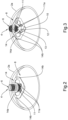
Figure 2 is an axonometric view, from above, of a detail of the cylinder according to the invention; -
Figure 3 is an axonometric view, from below, of the same detail asFigure 2 ; -
Figures 4 and 5 are front, cross-sectional views of the cylinder according to the invention in two different configurations of use. - With particular reference to these figures,
reference numeral 1 globally denotes a non-refillable cylinder. - First of all, the
non-refillable cylinder 1 comprises at least onehollow container body 2 adapted to contain pressurized gas and provided with at least oneend portion 2a on which at least oneport 3 for the gas outflow is obtained. - In particular, the
container body 2 is conformed substantially cylindrical. - The
cylinder 1 then comprises at least one one-way valve 4 associated with thecontainer body 2, adapted to allow the gas to escape from thecontainer body 2 and provided with at least one threadedclamping portion 5 coupleable to theport 3 in a threaded manner. - In actual facts, the
clamping portion 5 is shaped to fit snugly into theport 3 and can, in this way, mate securely thereto to prevent unwanted gas leakage through it. - As visible in
Figures 1 ,4 and 5 , thevalve 4 comprises: - at least one
outer body 6 provided with acavity 6a obtained through; and - at least one
spool 7 fitted into thecavity 6a in a movable manner and adapted to allow/prevent the passage of gas through the cavity itself as a result of its own movement with respect to theouter body 6. - Conveniently, the
cylinder 1 comprises retaining means 8 associated with thecontainer body 2 and adapted to prevent thevalve 4 from being removed from thecontainer body 2. - In this case, the retaining means 8 comprise at least one retaining
body 8 arranged internally to thecontainer body 2 where itsport 3 is located. - The fact of arranging the
retaining body 8 internally within thecontainer body 2 ensures that the same cannot be reached by the user and possibly tampered with, proving to be a particularly advantageous technical expedient to prevent thevalve 4 from being removed from thecontainer body 2. - Specifically, the
retaining body 8 comprises at least oneflexible portion 11 defining apassage hole 9 aligned with theport 3 along an axis A and adapted to house one stretch of thevalve 4 within it (see, in this regard,Figures 4 and 5 ). In other words, thevalve 4 is arranged in a pass-through manner within thepassage hole 9. - According to the invention, the
valve 4 comprises at least one retainingend 10 of substantially widened cross-section adapted to allow thevalve 4 to be fitted into thecontainer body 2 and, at the same time, adapted to prevent thevalve 4 from being pulled out of thecontainer body 2. - According to a preferred embodiment, illustrated in the figures, the retaining
end 10 has a truncated-cone conformation. Different conformations of the retainingend 10, such as truncated ball or the like, cannot however be ruled out. - For this purpose, the retaining
end 10 has a convergent section in the direction of moving away from theclamping portion 5. - In fact, the increasing thickness along the aforementioned direction of moving away allows the
flexible portion 11 to be deformed and thepassage hole 9 to be progressively enlarged, thus allowing the passage through it of theretaining end 10 and, therefore, thevalve 4 to be fitted into thecontainer body 2. - At the same time, this precise conformation prevents the opposite movement, i.e., the passage of the
retaining end 10 through thepassage hole 9 as a result of the fitting of thevalve 4 into thecontainer body 2. - Through the specific conformation of the retaining
end 10 it is, therefore, possible to avert any attempts to remove thevalve 4 from thecontainer body 2, complying with the current regulations previously mentioned. - Going into more detail, it should be explained that the
valve 4 is movable along the axis A between: - a pressurization position, wherein the
clamping portion 5 is coupled to theport 3 and the retainingend 10 is spaced apart from the flexible portion 11 (Figure 4 ); and - a safety position, wherein the
clamping portion 5 is uncoupled from theport 3 and the retainingend 10 is arranged to stop against the flexible portion 11 (Figure 5 ). - During the normal use of the
cylinder 1, thevalve 4 is placed in the pressurization position, thus preventing gas leakage through theport 3 and allowing only gas delivery through thecavity 6a due to the movement of thespool 7. - On the other hand, in the event of damage to the
cylinder 1 or attempts to tamper therewith, thevalve 4 automatically places itself in the safety position, thus remaining firmly anchored to theretaining body 8 and being, in doing so, substantially immovable from thecontainer body 2. - According to the invention, the
cylinder 1 comprises venting means 12 associated with thevalve 4 and adapted to allow the escape of the gases contained in thecontainer body 2 when thevalve 4 is in the safety position. - Advantageously, the venting means 12 comprise at least one
unthreaded stretch 13 formed on thevalve 4 between theclamping portion 5 and the retainingend 10, with a smaller diameter than that of theclamping portion 5. - Specifically, in the safety position, the
unthreaded stretch 13 is positioned where theport 3 is located and defines, with the walls of the latter, a perimeter space S adapted to allow the gases to escape from the container body 2 (see, in this regard, the magnified view inFigure 5 ). - This expedient proves particularly convenient and makes it possible, in particular, to fix the related problems of the prior art previously complained of.
- In fact, as already anticipated, damage to the
cylinder 1 or an attempt to tamper with thevalve 4 causes the valve to be displaced from the pressurization position to the safety position. - Under this circumstance, should there be a certain amount of pressurized gas in the
container body 2, the gas could immediately and effectively escape from the container body itself by crossing the perimeter space S, thus bringing thecontainer body 2 to ambient pressure. - In actual facts, in the event of a road accident and consequent damage to the
cylinder 1, the technical expedient in question makes it possible to prevent thevalve 4 from escaping from thecontainer body 2 due to the thrust exerted by the gases, keeping the latter in the safe position in order to allow the gases to escape completely. - Similarly, the venting means 12 also allow minimizing the risks to the user in case of imperfect coupling between the
port 3 and the clampingportion 5. - This circumstance, too, involves, in fact, placing the
valve 4 in the safety position, thus allowing the gases to flow through the perimeter space S to the outside and thus bringing thecontainer body 2 to a pressure substantially equal to the ambient pressure. - Finally, as far as the disposal cycle is concerned, it is possible to minimize the risks to the attendant staff by simply placing the
valve 4 to the safety position and thus venting the gases contained in thecontainer body 2 to the outside, returning the latter to ambient pressure. - It should be noted that according to the preferred embodiment, shown in the figures, the threaded
stretch 13 is completely threadless, therefore provided with a completely "smooth" surface. - Alternative embodiments are however considered technically equivalent wherein the unthreaded
stretch 13 is partly provided with a threading interrupted by means of at least one longitudinal groove adapted to allow the gas to escape. Conveniently, at least one of either the clampingportion 5 or the unthreadedstretch 13 has a substantially right-cylinder conformation. - Preferably, both the clamping
portion 5 and the unthreadedstretch 13 have a substantially right-cylinder conformation. - Advantageously, as visible in
Figures 2 and 3 , theflexible portion 11 comprises a plurality offlexible elements 11a having elongated conformation and arranged in a radial pattern with respect to each other around the axis A. - Specifically, the
flexible portion 11 comprises fourflexible elements 11a. - The use of four
flexible elements 11a allows, in fact, optimizing the production cycle of thecylinder 1 as well as its operating efficiency; it is easy, however, to appreciate how the number offlexible elements 11a may be different and, e.g., higher. - More specifically, the
flexible elements 11a are arranged at a substantially constant angular distance from each other. - In other words, the
flexible elements 11a are arranged at 90° to each other. - The flexibility of the
flexible elements 11a allows them to expand elastically and, therefore, to enlarge thepassage hole 9 to allow the passage of the retainingend 10 during the insertion of thevalve 4 into thecontainer body 2. Advantageously, theflexible elements 11a are made of metallic material. - In particular, the
flexible elements 11a are made of stainless steel. - More specifically, the
flexible elements 11a are made of ferritic stainless steel. Specifically, theflexible elements 11a are made of Aisi430. - The particular choice of this material is very advantageous since it gives the
flexible elements 11a good springback as a result of the insertion of the retainingend 10 into thepassage hole 9 and reduces oxidation triggering. - The use of a different material cannot, however, be ruled out for making the
flexible elements 11a that allow, however, the latter for adequate springback as a result of the complete insertion of thevalve 4. - Conveniently, the retaining
body 8 comprises at least onecoupling portion 14 associated with theflexible portion 11 and adapted to enable the coupling of the retainingbody 8 to theend portion 2a (seeFigures 2 and 3 ). - Specifically, the
coupling portion 14 comprises at least onebase surface 14a and a plurality of weldingprotrusions 14b formed on thebase surface 14a and arranged in a radial pattern around the axis A. - Specifically, the
coupling portion 14 comprises fourwelding protrusions 14b. As visible in the aforementioned figures, thewelding protrusions 14b are arranged at a constant angular distance from each other. - The presence of the
welding protrusions 14b allows the retainingbody 8 to be attached to theend portion 2a by means of projection welding, making a particularly firm and durable coupling between the two. - It has in practice been ascertained that the described invention achieves the intended objects.
- In particular, the fact is emphasized that the special arrangement of the retaining means ensures that it is impossible to tamper with them and, therefore, to remove the valve from the container body.
- In addition, the special expedient of providing venting means allows the gas content of the container body to be removed easily and effectively, thus minimizing the risks to the user and to the operators involved in the cylinder disposal.
Claims (10)
- Non-refillable cylinder (1), comprising:- at least one hollow container body (2) adapted to contain pressurized gas and provided with at least one end portion (2a) on which at least one port (3) for the gas outlet is obtained;- at least one one-way valve (4) associated with said container body (2), adapted to allow the gas to escape from said container body (2) and provided with at least one threaded clamping portion (5) coupleable to said port (3) in a threaded manner;- retaining means (8) associated with said container body (2) and adapted to prevent said valve (4) from being removed from said container body (2);characterized by the fact that:- said retaining means (8) comprise at least one retaining body (8) arranged internally to said container body (2) where said port (3) is located and comprising at least one flexible portion (11) defining a passage hole (9) aligned with said port (3) along an axis (A) and adapted to house a stretch of said valve (4) within it;- said valve (4) comprises at least one retaining end (10) of substantially widened conformation, adapted to allow said valve (4) to be fitted into said container body (2) and adapted to prevent said valve (4) from being pulled out of said container body (2), said valve (4) being movable along said axis (A) between a pressurization position, wherein said clamping portion (5) is coupled to said port (3) and said retaining end (10) is spaced apart from said flexible portion (11), and a safety position, wherein said clamping portion (5) is uncoupled from said port (3) and said retaining end (10) is arranged to stop against said flexible portion (11);
and by the fact that- said cylinder (1) comprises venting means (12) adapted to allow the escape of the gases contained in said container body (2) when said valve (4) is in said safety position. - Cylinder (1) according to claim 1, characterized by the fact that:- said venting means (12) comprise at least one unthreaded stretch (13) formed on said valve (4) between said clamping portion (5) and said retaining end (10), having a smaller diameter than that of said clamping portion (5); and by the fact that- in said safety position, said unthreaded stretch (13) is positioned where said port (3) is located and defines with the walls of the latter a perimeter space (S) adapted to allow the gases to escape from said container body (2).
- Cylinder (1) according to one or more of the preceding claims, characterized by the fact that said retaining end (10) has a convergent section in the direction of moving away from said clamping portion (5).
- Cylinder (1) according to one or more of the preceding claims, characterized by the fact that said retaining end (10) has a substantially truncated-cone conformation.
- Cylinder (1) according to one or more of the preceding claims, characterized by the fact that said flexible portion (11) comprises a plurality of flexible elements (11a) having elongated conformation and arranged in a radial pattern with respect to each other around said axis (A).
- Cylinder (1) according to claim 5, characterized by the fact that it comprises four of said flexible elements (11a).
- Cylinder (1) according to claim 4 or 5, characterized by the fact that said flexible elements (11a) are arranged at a substantially constant angular distance from each other.
- Cylinder (1) according to one or more of the preceding claims, characterized by the fact that said flexible elements (11a) are made of metallic material.
- Cylinder (1) according to one or more of the preceding claims, characterized by the fact that said retaining body (8) comprises at least one coupling portion (14) associated with said flexible portion (11) and adapted to enable the coupling of said retaining body (8) to said end portion (2a).
- Cylinder (1) according to claim 9, characterized by the fact that said coupling portion (14) comprises at least one base surface (14a) with which said flexible elements (11a) are associated and a plurality of welding protrusions (14b) formed on said base surface (14a) and arranged in a radial pattern around said axis (A).
Applications Claiming Priority (1)
| Application Number | Priority Date | Filing Date | Title |
|---|---|---|---|
| IT102023000016773A IT202300016773A1 (en) | 2023-08-04 | 2023-08-04 | NON-REFILLABLE CYLINDER |
Publications (3)
| Publication Number | Publication Date |
|---|---|
| EP4502454A1 true EP4502454A1 (en) | 2025-02-05 |
| EP4502454C0 EP4502454C0 (en) | 2026-01-28 |
| EP4502454B1 EP4502454B1 (en) | 2026-01-28 |
Family
ID=88414021
Family Applications (1)
| Application Number | Title | Priority Date | Filing Date |
|---|---|---|---|
| EP24191384.7A Active EP4502454B1 (en) | 2023-08-04 | 2024-07-29 | Non-refillable cylinder |
Country Status (4)
| Country | Link |
|---|---|
| US (1) | US12584593B2 (en) |
| EP (1) | EP4502454B1 (en) |
| CN (1) | CN119435954A (en) |
| IT (1) | IT202300016773A1 (en) |
Citations (5)
| Publication number | Priority date | Publication date | Assignee | Title |
|---|---|---|---|---|
| US3684132A (en) * | 1970-02-09 | 1972-08-15 | Inland Steel Co | Disposable liquefied gas container and burner outlet fitting therefor |
| EP0768485A1 (en) * | 1995-10-11 | 1997-04-16 | Amtrol Inc. | Valves for pressurized containers |
| US6932238B2 (en) * | 2003-01-28 | 2005-08-23 | Air Liquide Advanced Technologies U.S. Llc | Non-refillable valve device |
| US9791050B2 (en) * | 2013-09-27 | 2017-10-17 | Luxembourg Patent Company S.A. | Gas shut-off device |
| IT202100007097A1 (en) * | 2021-03-24 | 2022-09-24 | Renato Rinaldi | METHOD OF CREATING A CYLINDER FOR GAS UNDER PRESSURE AND RELATIVE CYLINDER |
Family Cites Families (2)
| Publication number | Priority date | Publication date | Assignee | Title |
|---|---|---|---|---|
| US3143253A (en) * | 1961-08-17 | 1964-08-04 | Turner Corp | Center vented pressure container |
| US20240288128A1 (en) * | 2023-02-26 | 2024-08-29 | Kyle Brown | Pressure relief system, pressure safety device and tool, pressurized container system, processes, and method of use |
-
2023
- 2023-08-04 IT IT102023000016773A patent/IT202300016773A1/en unknown
-
2024
- 2024-07-19 US US18/778,494 patent/US12584593B2/en active Active
- 2024-07-29 EP EP24191384.7A patent/EP4502454B1/en active Active
- 2024-08-02 CN CN202411058479.4A patent/CN119435954A/en active Pending
Patent Citations (5)
| Publication number | Priority date | Publication date | Assignee | Title |
|---|---|---|---|---|
| US3684132A (en) * | 1970-02-09 | 1972-08-15 | Inland Steel Co | Disposable liquefied gas container and burner outlet fitting therefor |
| EP0768485A1 (en) * | 1995-10-11 | 1997-04-16 | Amtrol Inc. | Valves for pressurized containers |
| US6932238B2 (en) * | 2003-01-28 | 2005-08-23 | Air Liquide Advanced Technologies U.S. Llc | Non-refillable valve device |
| US9791050B2 (en) * | 2013-09-27 | 2017-10-17 | Luxembourg Patent Company S.A. | Gas shut-off device |
| IT202100007097A1 (en) * | 2021-03-24 | 2022-09-24 | Renato Rinaldi | METHOD OF CREATING A CYLINDER FOR GAS UNDER PRESSURE AND RELATIVE CYLINDER |
Also Published As
| Publication number | Publication date |
|---|---|
| EP4502454C0 (en) | 2026-01-28 |
| EP4502454B1 (en) | 2026-01-28 |
| CN119435954A (en) | 2025-02-14 |
| IT202300016773A1 (en) | 2025-02-04 |
| US20250043921A1 (en) | 2025-02-06 |
| US12584593B2 (en) | 2026-03-24 |
Similar Documents
| Publication | Publication Date | Title |
|---|---|---|
| US4880134A (en) | Protective cap assembly | |
| EP2826745A1 (en) | Overpressure valve of a spear tube valve | |
| US20190388720A1 (en) | Tool and Method for Draining a Fire Sprinkler System and a Fire Sprinkler | |
| EP4502454B1 (en) | Non-refillable cylinder | |
| US20080196766A1 (en) | Breakaway self-sealing safety valve | |
| MX2014011880A (en) | Pressure relief device for pressurized container. | |
| KR20160123355A (en) | Extinguishing-fluid-nozzle system for stationary fire-extinguishing systems, having an aperture ring, and extinguishing-fluid nozzle and aperture ring for the same | |
| CA2282129C (en) | Valve for a container of pressurized fluid fitted with a lever for controlling the passage of the fluid | |
| EP3655683B1 (en) | Combination of safety valve, container and dispensing valve | |
| US20060042617A1 (en) | Valve for air tank | |
| JP5977295B2 (en) | Hose fittings | |
| EP3114076B1 (en) | Valve cover | |
| US20040244836A1 (en) | Protection and tamper notification device for use with a valve | |
| US7147228B2 (en) | Pressure relief device | |
| US6955182B2 (en) | Tamper proof relief valve for gas cylinder | |
| EP2030944A2 (en) | Extractor device adapted for insertion into an opening of a beverage container and beverage container provided with extractor device | |
| US20080007011A1 (en) | Compressed gas cylinder valve seal having elastomeric overmolded surface | |
| US3684132A (en) | Disposable liquefied gas container and burner outlet fitting therefor | |
| WO2014170699A2 (en) | Valve - spear fitting for a keg | |
| ES2445240T3 (en) | Container with fiber winding with associated collar | |
| EP1750051A2 (en) | Gas cylinder with manual on/off and valve | |
| RU2779787C2 (en) | Valve assembly | |
| EP3521685B1 (en) | Pressure gas cylinder valve | |
| EP1198409B1 (en) | Keg-valve with anti-tampering means | |
| AU2005245038B2 (en) | Nozzle protector cap |
Legal Events
| Date | Code | Title | Description |
|---|---|---|---|
| PUAI | Public reference made under article 153(3) epc to a published international application that has entered the european phase |
Free format text: ORIGINAL CODE: 0009012 |
|
| STAA | Information on the status of an ep patent application or granted ep patent |
Free format text: STATUS: THE APPLICATION HAS BEEN PUBLISHED |
|
| AK | Designated contracting states |
Kind code of ref document: A1 Designated state(s): AL AT BE BG CH CY CZ DE DK EE ES FI FR GB GR HR HU IE IS IT LI LT LU LV MC ME MK MT NL NO PL PT RO RS SE SI SK SM TR |
|
| STAA | Information on the status of an ep patent application or granted ep patent |
Free format text: STATUS: REQUEST FOR EXAMINATION WAS MADE |
|
| 17P | Request for examination filed |
Effective date: 20250730 |
|
| GRAP | Despatch of communication of intention to grant a patent |
Free format text: ORIGINAL CODE: EPIDOSNIGR1 |
|
| STAA | Information on the status of an ep patent application or granted ep patent |
Free format text: STATUS: GRANT OF PATENT IS INTENDED |
|
| RIC1 | Information provided on ipc code assigned before grant |
Ipc: F17C 13/04 20060101AFI20250822BHEP |
|
| INTG | Intention to grant announced |
Effective date: 20250908 |
|
| GRAS | Grant fee paid |
Free format text: ORIGINAL CODE: EPIDOSNIGR3 |
|
| GRAA | (expected) grant |
Free format text: ORIGINAL CODE: 0009210 |
|
| STAA | Information on the status of an ep patent application or granted ep patent |
Free format text: STATUS: THE PATENT HAS BEEN GRANTED |
|
| AK | Designated contracting states |
Kind code of ref document: B1 Designated state(s): AL AT BE BG CH CY CZ DE DK EE ES FI FR GB GR HR HU IE IS IT LI LT LU LV MC ME MK MT NL NO PL PT RO RS SE SI SK SM TR |
|
| REG | Reference to a national code |
Ref country code: CH Ref legal event code: F10 Free format text: ST27 STATUS EVENT CODE: U-0-0-F10-F00 (AS PROVIDED BY THE NATIONAL OFFICE) Effective date: 20260128 Ref country code: GB Ref legal event code: FG4D |
|
| REG | Reference to a national code |
Ref country code: DE Ref legal event code: R096 Ref document number: 602024002287 Country of ref document: DE |
|
| REG | Reference to a national code |
Ref country code: IE Ref legal event code: FG4D |
|
| U01 | Request for unitary effect filed |
Effective date: 20260226 |
|
| U07 | Unitary effect registered |
Designated state(s): AT BE BG DE DK EE FI FR IT LT LU LV MT NL PT RO SE SI Effective date: 20260304 |